1
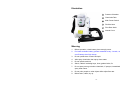
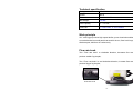
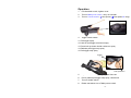
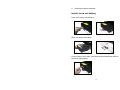
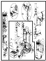
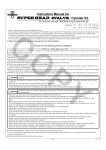
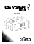
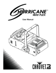
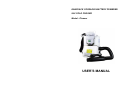
 KNAPSACK CORDLESS BATTERY POWERED
ULV COLD FOGGER
Model : Pioneer
Model: Pioneer
User’s Manual
USER’S MANUAL
CONTENTS
Contents ······························································································ 1
Illustration ···························································································· 2
Warning ······························································································· 2
Technical specification ········································································ 3
Work principle ····················································································· 3
Flow rate knob····················································································· 3
Operation ···························································································· 4
Install, move out battery…………...……………………...……….……...5
Spare parts list····················································································· 6
Inform
Due to further improvement, we are sorry if could not inform individually.
-1-
Illustration
A
A
Pressure Chamber
B
Chemicals Tank
C
Main Power Switch
D
Flexible Hose
E
Flow Rate Knob
F
Nozzle Cover
B
C
D
E
F
Warning
1.
Before operation, check battery have enough power.
2.
For better maintain battery, please remember every 2 month, run
out off battery then fully charge.
3.
Do not upside down if tank has liquid.
4.
After spray chemicals, then spray clean water.
5.
Do not splash machine.
6.
Switch, cable’s insulating layer, hose, gasket broke, fix.
7.
Do not spray strong corrosive chemicals, if sprayed, immediately
spray clean water.
8.
Do not point people or other object while adjust flow rate.
9.
Before store, clean, dry up.
-2-
Technical specification
Voltage
DC
24 V
Power
450 W
Dimension
33 x 24 x 49 CM
Net Weight
9.70 KG
Tank capacity
5 L / 1.3 GAL.
Flow rate
0 - 0.325 L/min, 0 - 9.61 OZ/min
Work principle
ULV cold fogger produce high-speed airflow, press chemicals solution
to nozzle breaks into small particle around 20 micron, float in air longer,
eliminate pest, disinfect air continuously.
Flow rate knob
Turn “Flow rate knob” to clockwise direction, decrease flow rate,
produce smaller fog droplet;
Turn “Flow rate knob” to anti-clockwise direction, increase flow rate,
produce bigger fog droplet;
Flow Rate Knob -3-
Operation
1.
Fill chemicals to tank, tighten cover.
2.
Turn on Main power switch, carry on shoulder.
3.
Turn on Handle switch (Ⅰ-slow speed, Ⅱ-fast speed, O -stop).
4.
Trigger under handle
4.1 Pull trigger spray.
4.2 Hold on-pull trigger continuous spay.
4.3 Press lock up button inside continuous spray.
4.4 Release pull trigger stop spray.
4.5 Pull trigger stop spray.
Trigger Lock Up Button 5.
Adjust flow rate knob for appropriate flow rate.
6.
Pull or release pull trigger stop spray, close knob.
7.
Turn off Handle switch,
8.
Please remember turn off Main power switch.
-4-
9.
Discharge residual chemicals.
Install, move out battery,
Push down battery catch device,
Move out battery along slide,
Push in battery along slide, catch device will automatically rebound
back lock appropriately.
-5-
Spare parts list
Item No.
Spare parts name
Quantity
Remark
1
Tank
1
2
Gasket
1
3
Cover
1
4
Connecting ring
1
5
Pressing buckle
1
6
Spring
3
Φ6.5
7
PVC Pipe
1
Φ4×Φ6×1900mm
8
PVC Pipe
1
Φ4×Φ6×1800mm
9
Nut
2
10
Fixed sets
2
11
Nut
2
12
Suction head accessory
1
13
PVC Pipe
1
14
Suction head
1
15
Filter
1
16
Screw
6
17
Cover
1
18
Self-locking block
1
19
Brand label
1
20
Spade hook
1
21
PTFE pipe
2
Φ6×Φ4×5
22
Screw
1
ST4.2×13
23
Fixed plate
1
24
Screw
5
M4×10
25
Screw
2
M6×20
26
Flat wash
2
6
27
Screw
9
M4×10
28
Fixed ring
1
29
Nut
2
30
Self-locking stand
1
-6-
50×42×3.5
Φ4×Φ6×250mm
ST2.9×8.5
M3
31
Screw
2
ST3.5×13
32
Screw
2
M3×10
33
Nut
2
M4
34
Flat
3
4
35
Rivet
2
3×5.5
36
Spring card
1
37
Fixed plate
1
38
PTFE pipe
2
Φ6×Φ4×13
39
Rivet
2
3.5×50
40
Torsional spring
2
41
Rolling bearing
2
42
Hook
1
43
Pin
1
44
Storage battery
1
wash
45
46
Connecting ring
2
47
Water-proof joint
2
48
Sleeve
8
49
Connecting strip
1
50
Pressure chamber
1
51
Switch
1
52
Seal
1
53
Motor assembly
1
54
Motor plate
1
55
Screws
17
56
Butt plate
1
57
Electricity display board
1
58
Control board
1
59
Gasket
4
Ф3
60
Screw
4
M3×12
61
Rear housing
1
62
ST2.9×16
-7-
Voltage Show1-1
63
Bellows
1
64
Handle, under part
1
65
Screws
1
66
Handle, top part
1
67
Switch
1
68
Button
1
69
Slide block
1
70
Compression spring
1
71
Valve switch button
1
72
Compression spring
1
73
Adjustable
1
74
Pulley
1
75
Rivet
1
2×13
76
Rivet
1
3×18
77
Rivet
1
3×13
78
Valve core
1
79
O-ring
1
Ф5.1×1.6
80
O-ring
1
Ф3×1.25
81
Valve
1
82
Extension spring
1
83
Screw
1
84
Accelerator knob
1
85
Adjustable lever
1
86
O-ring
1
Φ5×1.5
87
Screw
3
ST1.9×6
88
Limited block
1
89
Screw
2
90
Nozzle cover
1
91
Screw
1
M4×16
92
Nut
7
M4
93
O-ring
1
Φ56×3
94
Vortex device
1
block
-8-
ST2.9×25
M3×12
ST4.2×16
95
PVC Pipe
1
Φ4×Φ6×100mm
96
Screw
3
ST2.9×13
-9-
74 73
I
1 : 2
68
42
69
71
61
60
59
36
37
78
65
77
64
79
80
II
1 : 2
38 39
63
75
76
70
41
40
35
72
66
81
58
55
82
57
56
55
67
7
8
9
54
6
96
4
10
II
3
2
11
53
5
95
94
26 25
93
91 92
12
1
52
13
51
90
14
15
89
16
50
17
24
18
19
20
49
48
47
46
27
28
29
21 22 23
43
32
92
44
34 33
I
31
30
87
85
88 86
83
84