1
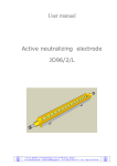
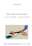
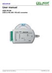
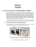
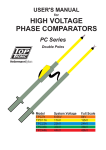
User manual
Active neutralizing electrode
JO96/1/L
P.P.U.H. MiZiAK, ul.T.B.Żeleńskiego 17/35, 95-100 Zgierz, Poland
www.miziak.zgierz.eu, email: [email protected], tel.: (+48) 42-278-20-71, fax.: (+48) 42-278-20-86
Table of contents
1
2
3
3
3
4
5
6
8
8
Doc.:Neutralizing Electrode JO96_1_L Manual v.B15
Front page
Table of contents
Introduction
Principles of operation neutralizer
Description of electrode
Rated data of electrode
Arrangements of electrodes
Installation
Usage
Troubleshooting
P.P.U.H. MiZiAK, ul.T.B.Żeleńskiego 17/35, 95-100 Zgierz, Poland
www.miziak.zgierz.eu, email: [email protected], tel.: (+48) 42-278-20-71, fax.: (+48) 42-278-20-86
Introduction
Static electricity is a phenomenon by which excessive electric charges are created on objects. That
charges appear most frequently on materials of low electrical conductivity (insulators, dielectrics).
In some special cases they can accumulate on conductive objects insulated from the ground
(including human body).
Influence of electrostatic charges can result in numerous difficulties in technological processes,
create hazards for safety of workers, danger of fire or explosions, and disturb the operation
of electronic devices.
Electrode is a part of the set designed to actively neutralize excessive electrostatic charges that are
created on processed materials. Complete deionizer consists of high voltage power supply
(TZWN-05) and one or more pointed electrodes JO96/x/L connected to power supply with special
cable. It is an active pointed neutralizer of increased hv frequency.
Principles of operation neutralizer
Electrode(s) are placed near material that is to be neutralized. Power unit function is to provide
high voltage needed to create ions around the pins of electrodes. After turning power supply on, near
the points of electrode a powerful electric field is created. The result of this is partial (corona)
discharge. It causes intensive ionization of air molecules (disintegration to positive and negative
ions). Under electrostatic forces the electrified material attracts aprropriate (of opposite polarity) ions
that neutralize its charge.
JO96/x/L
Description of electrode
Electrode JO96 / 1 / L is designed for supply voltage 7kV 1,2kHz. It is built as monoblock,
nondemountable element. Duralumin 20x20x2mm C-bar constitutes the structure. Inside it there is
a conductive core with embedded pins. Ends are terminated with proper plastic insulators. Interiors
of electrodes are filled with insulation resin. At the bottom there are M5 threaded rods attached,
which serve for mounting on the machine. Electrode is combined to power supply output by highvoltage cable. Body of electrode should be fastened to frame of machine. Device is designed for
continuous operation.
P.P.U.H. MiZiAK, ul.T.B.Żeleńskiego 17/35, 95-100 Zgierz, Poland
www.miziak.zgierz.eu, email: [email protected], tel.: (+48) 42-278-20-71, fax.: (+48) 42-278-20-86
Doc.:Neutralizing Electrode JO96_1_L Manual v.B15
TZWN-05
Electrodes are manufactured on an individual order. Available usable length range of electrodes
is 100mm – 1900mm.
L
~ (L + 47)
23
Manner of marking:
pinned electrode JO96/1/L
JO96 - model
/1
- one connection terminal
/L
- electrode's usable length [mm]
Note:
The electrode's length together with the connection is about 50 mm longer than the usable length
of electrode!
If more than one electrode is in use, the total usable length of all the electrodes should also not
exceed 2600mm!
Type
Compatible item
Supply voltage
Length of a single electrode
Maximum total usable length of electrodes
Recommended total usable length of electrodes
Installation distance
Max. number of electrodes for one power supply
Operation mode
Ambient temperature
Air humidity
Operating position
Montage
Dimensions: width x height x length
Weight
JO96/1/L
power unit TZWN-05
7kVac, 1,2kHz
100 - 1900mm
2600 mm
< 2000 mm
3 – 20 mm
2
continuous
273-333 K
<80 %, non-condensing
any
M5 threaded rods
23 x 23 x (L+50) mm
0,65 kg/m
P.P.U.H. MiZiAK, ul.T.B.Żeleńskiego 17/35, 95-100 Zgierz, Poland
www.miziak.zgierz.eu, email: [email protected], tel.: (+48) 42-278-20-71, fax.: (+48) 42-278-20-86
Doc.:Neutralizing Electrode JO96_1_L Manual v.B15
Rated data
Arrangements of electrodes
Electrode JO96/1/L is equipped with single high voltage connection terminal. That allows not
more than two electrodes JO96/1/L being directly connected to the TZWN-05 power supply.
If more electrodes are necessary, transitional electrodes JO96/2/L should be applied.
Electrodes JO96/2/L are equipped with high voltage connection terminals on both ends and enable
cascading of the electrodes, ”one after the other”. Electrodes with one terminal are then applied in the
final place in a sequence.The electrode's connection terminals are protected with a special covering
insulators, mounted after joining the high-voltage cables.
Note:
The electrode's length together with the connection is about 85 mm longer than the usable length
of electrode!
P.P.U.H. MiZiAK, ul.T.B.Żeleńskiego 17/35, 95-100 Zgierz, Poland
www.miziak.zgierz.eu, email: [email protected], tel.: (+48) 42-278-20-71, fax.: (+48) 42-278-20-86
Doc.:Neutralizing Electrode JO96_1_L Manual v.B15
In those cases, where two or more electrodes are required, cascading connections are recommended.
High-voltage cables are shorter, which favorably affects capacitive loss of connection.
Installation
Note:
Device may not be installed in explosion hazard areas or environments with flammable substances!
Disconnect the power supply before carrying out work on the unit!
Electrical installation of device should be done by a skilled electrician with proper qualifications!
Fix electrode(s) firmly on machine, pointing its pins toward neutralized material. Electrode should
be installed at a distance of 3-20mm from the moving material (usually around 5mm). Do not allow
material to rub against electrode. At the bottom of electrodes there are factory-installed M5 threaded
rods. Spacing between rods is r = (L – 60) mm. Use brackets and screws from the assembly kit.
We recommend electrodes longer than 1500mm to be stiffened by embedding into alu U-profile
30x30x3 mm (as shown below). Long electrodes have a third fastening rod placed in the middle
of the active length L.
Doc.:Neutralizing Electrode JO96_1_L Manual v.B15
In neutralization of discontinuous materials (fabric, yarn, fibre...) one electrode can be used.
For continuous (foil, coated paper) the use of two electrodes, one on each side of the film (sheet) is
recommended. In this case planes of symmetry of electrodes should be displaced for at least 50 mm.
P.P.U.H. MiZiAK, ul.T.B.Żeleńskiego 17/35, 95-100 Zgierz, Poland
www.miziak.zgierz.eu, email: [email protected], tel.: (+48) 42-278-20-71, fax.: (+48) 42-278-20-86
To ensure maximum efficiency of operation, there should not be any metal elements at a distance
of 50mm from the electrode.
R>
=
50
m
m
Electrode of the neutralizer should be placed directly in front of the place, where the electrostatic
charge is to be removed. The necessary amount of electrodes and their location must be determined
experimentally.
The power unit should be located as close as possible to the electrodes and positioned in such a
way that its switch is easily accessible to operator. High voltage cable connecting the power supply
with the electrode should be relatively short. It should not touch the machine body (we recommend
placing in insulating tubes). It should be fixed to machine frame.
Do not lay the hv cable near sharp metal parts. Do not bend beyond the natural bending radius.
It is recommended to keep spacing and crossing with other cables at right angles.
Connect hv cable to the electrode's terminal and mount insulating sheath.
Aluminium body of JO96/x/L electrode and earthing connector
of TZWN-05 power supply
should be connected to the earthed machine frame, using delivered cables. Resistance of power
supply-electrode's body connection should not exceed the 0,5Ω.
It is necessary to ensure proper operation.
For more information about unit assembly - see: „Antistatic power unit TZWN-05 – user manual”.
Note:
Neutralizer is designed to be built into another machine. Therefore it should be powered from
the internal circuits of that machine so that the voltage is supplied only when the machine runs and
to keep safety functions!
P.P.U.H. MiZiAK, ul.T.B.Żeleńskiego 17/35, 95-100 Zgierz, Poland
www.miziak.zgierz.eu, email: [email protected], tel.: (+48) 42-278-20-71, fax.: (+48) 42-278-20-86
Doc.:Neutralizing Electrode JO96_1_L Manual v.B15
Limited current capacity of high voltage source limits the length of usable electrode. Electrode
JO96/x/L of a usable length of not more than 2600mm can be connected to one TZWN-05 power
unit. If more than one electrode is in use, the total usable length of all the electrodes should also not
exceed 2600mm. It is assumed here that the high-voltage connection cable is not longer than 1,5m.
The longer the cable, the shorter the maxim total possible length of electrodes.
Usage
Assembled unit is switched on with rocker button, located on the front panel, by putting it in
position I. Presence of voltage 230V is indicated with the control lamps (built-in in the switch). By
normal operation of TZWN-05 converter, a quiet buzz is audible, coming from the inside of housing.
To needles of electrode is fed a high voltage. In a dark area blue fireflies of corona discharges should
be visible on the tips of the needles.
Note:
Do not tamper with the electrodes during operation!
Maintenance and repair of equipment should be performed by qualified personnel with the
appropriate qualifications!
Correctness of the electrode's operation can be checked by bringing a neon lamp placed on
a insulating bar near to the electrode's points. The electric field around the needles should make
the lamp glow.
Note:
Many factors (friction, pressure, temperature...) can cause electrostatic charge to be generated once
again and accumulate on the material!
Electrode (as well as other modules) do not have elements that require special regular operational
service. Keep the device clean: dry, free from dust, dirt and chemicals.
Hoover regularly whenever it is necessary (especially electrodes). Periodic inspections should be
done paying attention to the mounting, condition of cables, isolation of the electrodes and needles
wear. Once a year verify effectiveness of anti-shock protection.
Troubleshooting
Inverter does not buzz,
no neutralization (neon lamp
placed near to hv cable or
electrode's pins do not glow)
No neutralization, power pack
works correctly
Possible reasons
Proceeding
Contaminated electrode – power
supply overload
Clean up
Damaged insulation of electrode power supply overload
Replace electrode
Corrupted hv cable insulation
Replace hv cable
Damaged inverter
Send power supply to the service
Broken hv cable
Check the cable, replace damaged
section
Defective grounding connection of
electrodes or power supply
Check wires and contacts
Unfavorable electrode arrangement Verify according to instruction
Damage of insulation of cables and electrodes is often visible in dark environment.
If the power supply itself is working properly, and the whole set causes choking of the inverter, then
following sections of electrodes should be joined, until detecting the item that caused the overload.
P.P.U.H. MiZiAK, ul.T.B.Żeleńskiego 17/35, 95-100 Zgierz, Poland
www.miziak.zgierz.eu, email: [email protected], tel.: (+48) 42-278-20-71, fax.: (+48) 42-278-20-86
Doc.:Neutralizing Electrode JO96_1_L Manual v.B15
Symptoms