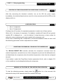
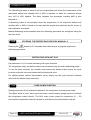
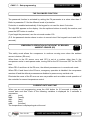
1
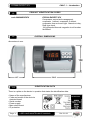
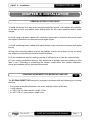
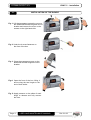
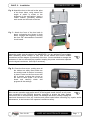
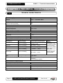
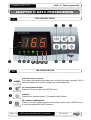
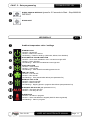
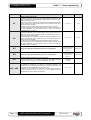
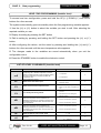
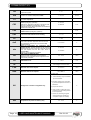
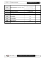
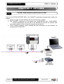
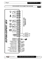
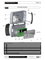
Manual Instruction Refrigeration controller ECP 200 Expert 2EV ECP200 EXPERT 2EV ENGLISH CONTENTS INTRODUCTION Page Page Page Page 3 4 4 4 1.1 1.2 1.3 1.4 General Product identification codes Overall dimensions Identification data INSTALLATION Page 5 Page 5 Page 6 2.1 2.2 2.3 General installation rules Standard equipment for mounting and use Board installation TECHNICAL CHARACTERISTICS Page 8 3.1 Technical characteristics TERMS OF THE WARRANTY Page 9 4.1 Terms of the warranty DATA PROGRAMMING Page Page Page Page Page Page Page Page Page Page Page Page Page Page Page Page Page Page Page Page Page 10 10 11 12 12 12 13 13 15 15 18 19 19 19 19 20 20 20 21 21 21 5.1 5.2 5.3 5.4 5.5 5.6 5.7 5.8 5.9 5.10 5.11 5.12 5.13 5.14 5.15 5.16 5.17 5.18 5.19 5.20 5.21 The control panel The front keypad LED display General Symbols Configuring and reading the set point Level one programming List of level one variables Level two programming List of level two variables HACCP alarm management Starting up the ECP200 EXPERT 2EV electronic controller Configurations Conditions for enabling / disabling the compressor Manual activation of the defrosting process Stopping the defrosting process manually Defrosting with hot gas The Pump-Down function The password function Emergency operation in the event of a broken ambient sensor (EO) Current date and time 6.1 TeleNET supervision / monitoring system OPTIONS Page 22 DIAGNOSTICS Page 23 7.1 Diagnostics ANNEXES Page 24 Page 25 Page 26 A.1 A.2 A.3 CE declaration of conformity ECP200 EXPERT 2EV connection diagram Exploded diagram CHAP. 1 CHAP. 2 CHAP. 3 CHAP. 4 CHAP. 5 CHAP. 6 CHAP. 7 CHAP. 1 - Introduction ECP200 EXPERT 2EV CHAPTER 1: INTRODUCTION GENERAL 1.1 DESCRIPTION: The ECP200 EXPERT 2EV is the new electrical board for cold rooms with single-phase compressor up to 2HP and up to 2 evaporating units. It allows complete control of all the components on a refrigeration system such as the compressor, the evaporator fans, defrosting element 1, defrosting element 2, room light and configurable auxiliary relay. APPLICATIONS: - Room with single motor condenser up to 2HP and double evaporating unit. - Complete control of single-phase static or ventilated refrigeration systems up to 2HP, with off-cycle or electrical defrosting and direct or pump-down compressor stop. - Control of evaporating unit only with freon solenoid consensus or remote motor condenser consensus. MAIN CHARACTERISTICS: - Reading and configuration of the room temperature to one decimal point. - Displays temperature parameter of evaporator 1 and 2 - Activation/deactivation of the system controller (stand-by) - Signalling of system alarms - System status LEDs and large display - Easy to use keypad - Control of the evaporator fans - Real time clock defrosts with one or two evaporators, each with end-of-defrost sensor. - Automatic and manual defrost control (static, with elements, with cycle inversion) - Management and control (direct or in pump-down mode) of the compressor up to 2HP - Button on board or door switch for turning on the room light - Alarm/auxiliary relay with parameter-configured activation. - Advanced HACCP function with detailed registration of the last temperature alarm to have occurred, and counter for previous alarms. - Integrated differential thermal magnetic circuit breaker for protecting and turning off the power to the refrigerating unit (to make the protection effective, derive the power supply of the utilities downstream of the differential thermal magnetic circuit breaker). - Self-extinguishing ABS cover with transparent door for accessing the thermal magnetic differential protection with IP65 protection, for use as a board outside the room. - RS485 output for connection to TeleNET supervision network. Rev. 01-09 USER AND MAINTENANCE MANUAL Page 3 CHAP. 1 - Introduction ECP200 EXPERT 2EV PRODUCT IDENTIFICATION CODES 1.2 code 200200EXP2EV ECP200 EXPERT 2EV Compressor control and management, evaporator 1 defrost, evaporator 2 defrost, evaporator fans and room light. Alarm/aux relay. Real time clock. 16A differential thermal magnetic circuit breaker Id=300mA OVERALL DIMENSIONS 1.3 dimensions in mm. 1.4 IDENTIFICATION DATA There is a plate on the device in question that states the identification data: • Name of the manufacturer • Code and model of the device’s electrical board • Serial number • Power supply • Max rated current • IP protection Page 4 USER AND MAINTENANCE MANUAL 200200EXP2EV Rev. 01-09 CHAP. 2 - Installation ECP200 EXPERT 2EV CHAPTER 2: INSTALLATION GENERAL INSTALLATION RULES 2.1 1. Install the device in an area that meets the protection criteria, and maintain the condition of the box as best as possible when drilling holes for the cable sheathing and/or cable clamps; 2. Avoid using multi-polar cables with conductors connected to inductive and power loads and signal conductors such as sensors and digital inputs; 3. Avoid combining power cables and signal cables in the same ducts (sensors and digital inputs) 4. Keep the connecting cables as short as possible, and do not let them coil up as coiling can subject the electronics to harmful inductive effects; 5. All the conductors used for cabling must be of sufficient size to take the required load; 6. If you need to extend the sensors, use conductors of suitable size and certainly no less than 1 mm². Extending or shortening the sensors could affect their default calibration; check and calibrate with an external thermometer. STANDARD EQUIPMENT FOR MOUNTING AND USE 2.2 The ECP200 EXPERT 2EV electronic controller is provided with the following for mounting and use: • • • • 3 ring seals to be placed between the screw and the surface of the box; 1 user manual; 1 x NTC 10K 1% black sensor, length =1.5m 2 x NTC 10K 1% grey sensor, length =3m Rev. 01-09 USER AND MAINTENANCE MANUAL Page 5 CHAP. 2 - Installation ECP200 EXPERT 2EV 2.3 INSTALLATION OF THE BOARD Fig. 1: Lift the transparent protective cover on the differential thermal magnetic circuit breaker and remove the cover on the screws on the right-hand side. Fig. 2: Undo the 4 screw fasteners on the front of the box. Fig. 3: Close the transparent cover on the differential thermal magnetic circuit breaker. Fig.4: Open the front of the box, lifting it and moving the two hinges to the end of their stroke. Fig. 5: Apply pressure on the sides of each hinge to release and fully remove the front. Page 6 USER AND MAINTENANCE MANUAL Rev. 01-09 CHAP. 2 - Installation ECP200 EXPERT 2EV Fig. 6: Attach the box to the wall at the point of the three holes, using screws the length of which is suited to the thickness of the wall behind. Insert a rubber washer (provided) between each screw and the back of the box. Fig. 7: Attach the front of the box back in place, re-inserting the hinges in their holes. Engage the hinges by moving the front 180° downwards to reveal the circuit board. Make all the electrical connections with reference to the annexed diagrams for the respective model (see the tables in the ANNEXES). You are advised to use suitable cable sheathing and/or clamps to fully seal all the cables and ensure reliable connections and the degree of protection of the box. You are advised to arrange the conductors in the box as neatly as possible, keeping the power conductors separate from the signal conductors. Use clips if necessary. ( Fig. 8: Close the front cover, making sure all the cables are safely fitted inside the box and the seal of the box is correctly in place. Fasten on the front cover with the 4 screws, re-using the o-rings on the neck of each screw. Turn on the board and carefully check and program all the settings. Make sure not to fasten the screws too tightly as to do so could damage the box and affect correct operation and tactile nature of the keypad. Install devices on all power lines connected to the EPC200 electronic controller to protect the latter against overcurrent due to shortcircuiting, which can damage the device. Always unplug the board and disconnect it from any inductive and power loads before executing any repairs and/or maintenance, in the interest of the operator’s maximum safety. ( Rev. 01-09 USER AND MAINTENANCE MANUAL Page 7 CHAP. 3 - Technical characteristics ECP200 EXPERT 2EV CHAPTER 3: TECHNICAL CHARACTERISTICS TECHNICAL CHARACTERISTICS 3.1 Power supply Voltage 230 V~ ± 10% 50Hz / 60Hz Max power consumption (electronic control only) ~ 7 VA Max permitted consumption (with all loads connected) 16A Environmental conditions Working temperature -5 to +50°C Storage temperature -10 to +70°C Relative ambient humidity Less than 90% Hr General characteristics Type of sensor connected NTC 10K 1% Resolution 0.1 °C. Precision of sensor readings ± 0.5 °C Reading range -45 to +45 °C Output characteristics (outputs with clean contacts) Description Relay installed Board output characteristics Defrost 1 (16A AC1 Relay) 10A 250V~ (AC3) (100000 cycles) 16A 250V~ (AC1) Defrost 2 Fans (16A AC1 Relay) 16A 250V~ (AC1) (16A AC1 Relay) 2.7A 250V~ (16A AC1 Relay) 16A 250V~ (AC1) (8A AC1 Relay) 8(3)A 250V~ Compressor (30A AC1 Relay) Room light Alarm / Aux (contact not live) General electrical protection (2HP) (AC3) Notes The total consumption of all the following utilities must not exceed 16A and the utiities’ power supply must derive from downstream of the thermal magnetic circuit breaker. 16A differential thermal magnetic circuit breaker, Id=300mA 4.5 kA breaking capacity Dimensional characteristics Dimensions 16.8cm x 9.7cm x 26.2cm (HxWxL) Insulation and mechanical characteristics Degree of protection for the box IP65 Material of the box ABS self-extinguishing Type of insulation Class II Page 8 USER AND MAINTENANCE MANUAL Rev. 01-09 CHAP. 4 - Terms of the warranty ECP200 EXPERT 2EV TERMS OF THE WARRANTY 4.1 The ECP200 EXPERT 2EV electronic controls are guaranteed against manufacturing defects for 24 months from the date given in the product identification code or the date on the product registration card, if available. In the event of a defect, the equipment must be returned, in suitable packaging, to our plant or authorized assistance centre after requesting the number for authorization to return the product. The Customer has the right to repair the defective equipment with his own manual labour and spare parts. The Customer assumes the risks for transport and covers the expenses. The warranty does not cover: • Damage due to tampering, negligence, lack of skill or unsuitable installation of the appliance. • Installation, use or maintenance not in conformity with the information and instructions provided with the appliance. • Repairs executed by unauthorized workers. • Damage due to unforeseen events such as lightning, natural disasters, etc. In all these cases the customer covers the entire cost of repairs. Our company may refuse to service the appliance under the warranty if it has been modified or converted without our knowledge. Under no circumstances can PEGO S.r.l. be held responsible for any loss of data and information, the cost of replacement goods or services, damage to objects and harm to people or animals, loss of sales or earnings, downtime, any direct, indirect or accidental damage, loss of assets, insurances, fines, or any other special or associated costs, whether contractual, non-contractual or due to negligence or other responsibilities relating to use of the product or its installation. Poor operation due to tampering, collisions, and unsuitable installation shall forfeit the warranty immediately. It is obligatory to comply with all the instructions in this manual and the conditions of use of the appliance. PEGO S.r.l. assumes no liability for any possible inaccuracies in this manual due to printing or transcription errors. PEGO S.r.l. reserves the right to make any changes to its products that it deems necessary or useful, without however compromising its products’ essential characteristics. Each new release of the manuals for PEGO products replaces all the previous ones. Unless stated otherwise, the warranty is in accordance with the laws in force and, in particular, article 1512 C.C. Disputes are settled at the court of Rovigo. Rev. 01-09 USER AND MAINTENANCE MANUAL Page 9 CHAP. 5 - Data programming ECP200 EXPERT 2EV CHAPTER 5: DATA PROGRAMMING THE CONTROL PANEL 5.1 n o p t q r s uvw THE FRONT KEYPAD 5.2 n AUXILIARY RELAY CONTROL o UP / MUTE BUZZER ALARM p STANDBY q SET AMBIENT TEMPERATURE Page 10 The version with alarm relay allows you to control the relay manually if AU=1; press the button for 2.5 sec to display the current date/time. Press for 2.5 sec to open the HACCP menu. Press this to stop the system. The standby light flashes. Press for 2.5 sec together with the mute button, when on the HACCP menu, to reset the registered HACCP alarms. USER AND MAINTENANCE MANUAL Rev. 01-09 CHAP. 5 - Data programming r s ECP200 EXPERT 2EV DOWN / MANUAL DEFROST (press for 2.5 seconds to Start – Stop MANUAL DEFROST ROOM LIGHT LED DISPLAY t Ambient temperature value / settings u STANDBY ICON Led OFF = Board OFF Led ON = Board ON and live Led flashing = Board in stand-by (cold outlet, defrost, fans disabled) v DOOR SWITCH / ROOM LIGHT ICON Led OFF = Door switch disabled or not in use and room light OFF Led ON = Room light ON Led Flashing = Door switch enabled and room light ON w COLD CALL ICON Led OFF = Cold call OFF Led ON = Cold call ON Led Flashing = Cold call ON but awaiting pause time C1 5.3 FAN CALL ICON Led OFF = Fan call OFF Led ON = Fan call ON Led Flashing = Fans paused after defrost (see parameter F5) DEFROST CALL ICON Led OFF = Defrost call OFF Led ON = Defrost call ON Led Flashing = Dripping phase in progress after defrost (see parameter D7) AUXILIARY RELAY ICON (with parameter AU=1) Led OFF = Aux relay call OFF Led ON = Aux relay call ON ALARM ICON Led OFF = No alarm in progress Led ON = Alarm activated then stopped (HACCP alarm registered) Led Flashing = Alarm in progress Rev. 01-09 USER AND MAINTENANCE MANUAL Page 11 CHAP. 5 - Data programming ECP200 EXPERT 2EV GENERAL 5.4 In the interest of safety and practicality, the ECP200 EXPERT 2EV system features two programming levels; the first is simply for configuring the SETPOINT parameters that are modified frequently, while the second is for programming and configuring the main parameters associated with the board’s various work modes. You have to exit level 1 programming before you can access the second level (you cannot go direct from level 1 to level 2). SYMBOLS 5.5 We shall use these symbols in the interest of practicality: • (t) the UP button for increasing values and silencing the alarm; • (u) the DOWN button 5.6 for decreasing values and starting the defrost process. CONFIGURING AND READING THE SET POINT 1. Press the SET button to display the current SETPOINT value (temperature) 2. Hold down the SET button and press the (t) or (u) button to change the SETPOINT value. Release the SET button to return to the room temperature. Your changes are saved automatically. Page 12 USER AND MAINTENANCE MANUAL Rev. 01-09 CHAP. 5 - Data programming ECP200 EXPERT 2EV LEVEL ONE PROGRAMMING (User level) 5.7 To access the level one configuration menu: 1. Press and hold both the (t) and (u) buttons for a few seconds until the programming variable appears on the display. 2. Release the (t) and (u) buttons. 3. Use the (t) or (u) button to select the variable you wish to edit. 4. After selecting the required variable you can: • Display its setting by pressing the SET button • Edit its setting by pressing and holding the SET button and pressing the (t) or button. After configuring the values, exit the menu by pressing and holding the (t) and buttons for a few seconds until the room temperature value appears. 5. The changes made to the variables are saved automatically when you exit configuration menu. LIST OF LEVEL 1 VARIABLES (User level) VARIABLES r0 d0 dd2 d21 d22 MEANING Temperature differential in relation to the main SETPOINT. Defrost interval (hours). In the case of two evaporators, the defrost process starts up at the same time for both (to delay the defrost process for evaporator 2, see variable dd2) and time d0 is loaded at the end of the previous defrost process. When d0=0 and dFr=0 Defrost disabled Delayed defrost for the second evaporator (sec). The defrost process of the second evaporator starts up after the defrost process of the first evaporator. The delay between the two defrost processes is configured in dd2. Setting dd2 is to run the two defrost processes in succession. This avoids overloading the electrical system during the defrost process in the event of limited power. When dd2=0, defrost processes 1 and 2 start simultaneously. Defrost end setpoint for evaporator 1. Defrost is not executed if the temperature detected by the defrost sensor is higher than the d21 value (defrost is timed if the sensor is broken). Defrost end setpoint for evaporator 2. Defrost is not executed if the temperature detected by the defrost sensor is higher than the d22 value (defrost is timed if the sensor is broken). first (u) (u) the 5.8 VALUES DEFAULT 0.2 - 10.0 °C 2°C 0 - 24 hours 4 hours 0 - 10 sec 0=defrost processes 1 and 2 start at the same time 0 sec -35 - 45 °C 15°C -35 - 45 °C 15°C d31 Max defrost time for evaporator 1 (minutes) 1 - 240 min 25 min d32 Max defrost time for evaporator 2 (minutes) 1 - 240 min 25 min 0 - 10 min 0 min 0 - 10 min 0 min d7 F5 Dripping time (minutes) At the end of the defrost process, the compressor and the fans stop for the d7 time configured and the defrost light on the front of the board flashes. Pause time for fans after defrost (minutes) To pause the fans for a period of time F5 after the dripping phase. This time counts down from the end of the dripping phase. If the dripping phase is not set, the fans are paused directly after the defrost process. The fan icon flashes during the pause time. Rev. 01-09 USER AND MAINTENANCE MANUAL Page 13 CHAP. 5 - Data programming ECP200 EXPERT 2EV VARIABLES VALUES DEFAULT -45 - A2 °C -45°C A1 - +45 °C +45°C Shows the temperature detected by the sensor of evaporator 1 Shows the temperature of the evaporator (or remains blank, if dE1 =1) Read-only tE2 Shows the temperature detected by the sensor of evaporator 2 Shows the temperature of the evaporator (or remains blank, if dE2 =1) Read-only dFr Enable evaporator defrost processes in real time When d0=0 and dFr=1, it is possible to configure up to 6 defrost processes in real time within a single day, using the parameters d41…d46 0 disabled 1 enabled 0 00.0 - 23.5 -- A1 A2 tE1 d41…d46 Page 14 MEANING Minimum temperature alarm Absolute temperature for the ambient sensor below which, after the Ald delay time, the EL low temperature alarm is activated and a record is made of this in the HACCP menu. When the EL alarm is activated, EL alternates with the temperature on the display, and the alarm relay, buzzer (which can be turned off), and alarm buzzer icon are all activated. The alarm turns off automatically when the conditions return to normal. The alarm light stays on to indicate the alarm has occurred and the event has been registered (see the HACCP menu to view and reset the temperature alarm concerned). Maximum temperature alarm Absolute temperature for the ambient sensor above which, after the Ald delay time, the EH high temperature alarm is activated and a record is made of this in the HACCP menu. When the EH alarm is activated, EH alternates with the temperature on the display, and the alarm relay, buzzer (which can be turned off) and alarm buzzer icon are all activated. The alarm turns off automatically when the conditions return to normal. The alarm light stays on to indicate the alarm has occurred and the event has been registered (see the HACCP menu to view and reset the temperature alarm concerned). Program timers for evaporator defrost processes It is possible to configure up to 6 timers for the defrost processes. The defrost process, or processes in the case of 2 evaporators, depends on the configuration of the variables dd2, d21, d22, d31, d32. The timer is in the HH.MM format, where HH is the hour and M the minutes in sets of ten (e.g. 0=0 min, 1=10 min, etc.). The flashing full stop (.) indicates this is a timer and not a temperature. USER AND MAINTENANCE MANUAL Rev. 01-09 CHAP. 5 - Data programming ECP200 EXPERT 2EV LEVEL TWO PROGRAMMING (Installer level) 5.9 To access level two configuration, press and hold the UP (t), DOWN (u) and LIGHT buttons for a few seconds. The system automatically goes into standby when the first programming variable appears. 1. Use the (t) or (u) button to select the variable you wish to edit. After selecting the required variable you can: 2. Display its setting by pressing the SET button 3. Edit its setting by pressing and holding the SET button and pressing the (t) or (u) button. 4. After configuring the values, exit the menu by pressing and holding the (t) and (u) buttons for a few seconds until the room temperature value appears. 5. The changes made to the variables are saved automatically when you exit the configuration menu. 6. Press the STANDBY button to enable the electronic control. LIST OF LEVEL 2 VARIABLES (Installer level) VARIABLES MEANING nrE Number of evaporators Configuring nrE=1 disables evaporator 2 and the defrost 2 output becomes a clean contact for calling the motor condensing unit (output parallel with compressor call). Output with clean contact. AC Status of the door switch input F3 Status of the fans with compressor OFF F4 Fan standby time during defrost dE1 dE2 Presence of sensor for evaporator 1 When the evaporator sensor is disabled, the defrosting processes run cyclically for the time d0 or according to the real time clock, and end when the time d31 elapses. Presence of sensor for evaporator 2 When the evaporator sensor is disabled, the defrosting processes run cyclically for the time d0 or according to the real time clock, and end when the time d32 elapses. dC Status of input for ‘man in room’ alarm d1 Type of defrost, with cycle inversion (hot gas) or elements. Rev. 01-09 5.10 VALUES DEFAULT 1 = 1 evaporator 2 2 = 2 evaporators 0 = Normally open 0 1 = Normally closed 0 = Fans run continuously 1 = Fans run only when compressor is ON 0 = The fans run during the defrost process 1 1 1 = The fans do not run during the defrost process 0 = sensor of evaporator 1 present 0 1 = sensor of evaporator 1 absent 0 = sensor of evaporator 2 present 0 1 = sensor of evaporator 2 absent 0 = NO 1 = NC 1= 0 hot gas 0 0= elements USER AND MAINTENANCE MANUAL Page 15 ECP200 EXPERT 2EV Ad Network address for connection to the TeleNET supervision system Ald 0 - 31 0 Delay time for signalling and displaying the minimum or maximum temperature alarm. 1…240 min 120 min C1 Minimum time between the shutdown and next startup of the compressor 0…15 min 0 min CE1 Compressor run time in event of broken ambient sensor (emergency operation) With CE1=0, emergency operation in the event of the E0 error is disabled: the compressor remains switched off and the defrost processes are disabled to preserve the residual cold. CE2 Compressor run time OFF in event of broken ambient sensor (emergency operation) CAL Correction of the ambient sensor reading -10…+10 0 Pc Status of compressor protection contact 0 = NO 1 = NC 0 0…5 minutes 0 doC tdo Fst Run time of compressor for door switch, when the door switch opens the evaporator fans turn off and the compressor continues to run for the time doC before turning off. Time for re-activating the compressor after opening of door. Normal operation of the control is restored when the door switch opens and after the tdo time has elapsed, and the door open alarm is activated (Ed). With tdo=0, the parameter is disabled. FAN disabling TEMPERATURE The fans remain at standstill if the temperature detected by the evaporator sensor is higher than the value of this parameter. Fd Differential for Fst tA Switching of status for NO – NC alarm relay 0…240 min 0= disabled 5…240 min 0 min 5 min 0…240 min 0 0 = disabled -45…+45°C +45°C 1…+10°C 2°C 0=energizes in event of alarm 1=de-energizes in event of alarm 1 LSE Minimum value of the setpoint -45 - HSE °C -45°C HSE Maximum value of the setpoint +45 - HSE °C +45°C 0= alarm relay 1= manual auxiliary relay commanded by the AUX button AU 2= automatic auxiliary relay controlled by the StA temperature set with 2°C differential Management of the RL6 configurable relay 3= pump down function 0 4= clean contact for callilng the motor condensing unit (AUX relay parallel to the compressor) 5 = Contact for controlling the guard element (AUX relay closed with compressor output not enabled). StA Page 16 Temperature set points for auxiliary relay USER AND MAINTENANCE MANUAL -45…+45°C Rev. 01-09 0 CHAP. 5 - Data programming ECP200 EXPERT 2EV 0 = displays only the set point P1 Password: for protection (enabled when PA is set at a number other than 0) PA Password (see P1 for type of protection) Yr 1= displays the set point, access to the light and AUX buttons 2= prevents access to programming 3= prevents access to level two programming 3 0...999 0 = function disabled 0 Year configuration 0...99 - Mo Month configuration 1...12 - dy Day configuration 1...31 - Hr Hour configuration 0...23 - min Minute configuration 0...59 - reL Software release The software version Read-only Rev. 01-09 USER AND MAINTENANCE MANUAL Page 17 ECP200 EXPERT 2EV 5.11 HACCP ALARM MANAGEMENT The EL low temperature alarm is activated at the end of the Ald time when the ambient sensor temperature is ≤ A1. The EH high temperature alarm is activated at the end of the Ald time when the ambient sensor temperature is ≥ A2. During a high or low temperature alarm, the temperature alternates with EH or EL on the display; and the alarm relay, buzzer (which can be silenced) and alarm buzzer icon (flashing) are activated. The alarm signals stop automatically when normal operation is restored (the alarm relay is deactivated, the buzzer stops and the display returns to normal). The alarm buzzer icon, however, remains on (steady) to indicate the EH or EL alarm has been activated and that the event has been registered (see the HACCP menu to view and reset the temperature alarm that has occurred). An alarm log states the date the last EH or EL event occurred, its duration and the maximum or minimum temperature reached. There is also a counter that indicates the number of alarms to have occurred since the last alarm reset. To view a temperature alarm, access the HACCP menu (press the mute button for 2.5 seconds). It is possible to reset the alarm registered in the menu by pressing and holding the mute and SET buttons for 2.5 seconds. The buzzer beeps to confirm the alarm is cancelled. To exit the menu, wait for 10 seconds without touching any of the buttons, or press the up and down arrow buttons at the same time. The variables in the HACCP menu are read-only and are as follows: VARIABLES MEANING E## Indicates the last temperature alarm to have occurred ### Peak temperature value reached during last EH or EL alarm y## Year the last temperature alarm started M## VALUES DEFAULT EH = high temperature alarm EL = low temperature alarm -- = no alarm occurred since last reset Read only -45…+45°C --- = no alarm occurred since last reset Read only y00 – y99 y-- = no alarm occurred since last reset Read only Month the last temperature alarm started M01 – M12 M-- = no alarm occurred since last reset Read only d## Day the last temperature alarm started d01 – d31 d-- = no alarm occurred since last reset Read only h## Hour the last temperature alarm started h00 – h24 h-- = no alarm occurred since last reset Read only m## Minutes the last temperature alarm started m00 – m59 m-- = no alarm occurred since last reset Read only t00 – t99 t-- = no alarm occurred since last reset Read only C00 – C99 C-- = no alarm occurred since last reset Read only t## Time (hours) the last temperature alarm lasted Counter indicating the number of temperature alarm events occurred C## Page 18 (when the data is registered for an alarm event, the reading on the counter increases by one and the counter indicates whether other alarms occurred previously. The counter is reset at the same time as resetting the registered alarm (press the mute and SET button x 5sec.) The counter increases by one whenever a new temperature alarm occurs). USER AND MAINTENANCE MANUAL Rev. 01-09 CHAP. 5 - Data programming ECP200 EXPERT 2EV STARTING UP THE ECP200 EXPERT 2EV ELECTRONIC CONTROLLER 5.12 After fully connecting the electronic controller, turn on the 230 Vac power supply; immediately, the electrical board emits a sound for a few seconds and all the LEDs on the display switch on. CONFIGURATIONS Use of 1 evaporator Use of 2 evaporators 5.13 Configure the nrE (number of evaporators) parameter to select one of these options. When nrE=1, the sensor of evaporator 2 is disabled, variables d22 and d32 are ignored, variable tE2 is displayed as ---, and the defrost 2 output becomes a clean contact for calling the motor condensing unit (output parallel with compressor call) In the event of defrosting with 2 evaporators, normal thermostatation does not occur until the defrosting processes for both evaporators have ended. CONDITIONS FOR ENABLING / DISABLING THE COMPRESSOR 5.14 The ECP200 EXPERT 2EV controller activates the compressor command when the ambient temperature exceeds the sum of the configured set point and the differential (r0); and deactivates the compressor when the ambient temperature is less than the configured set point. If you decide to select the Pump-Down function (parameter AU=4), refer to chapter 5.15 on the conditions for activating/deactivating the compressor. MANUAL ACTIVATION OF THE DEFROSTING PROCESS To start the defrosting process, simply press the 5.15 button for a few seconds; this activates the relay of the elements when the conditions are right. Rev. 01-09 USER AND MAINTENANCE MANUAL Page 19 ECP200 EXPERT 2EV The defrosting process of each of the two evaporators ends when the temperature of the associated defrost end variable (d21 or d22) is reached, or when the maximum defrost time (d31 or d32) elapses. The delay between the processes (variable dd2) is also factored in. A defrosting output is not activated when the temperature of the respective defrost end variable (d21 or d22) is found to be less than the temperature detected by the sensor of the evaporator concerned. Manual defrosting is also possible when the defrosting processes are configured using the real time clock. 5.16 Pressing the STOPPING THE DEFROSTING PROCESS MANUALLY button for 2.5 seconds when defrosting is in progress stops both defrosting processes. 5.17 DEFROSTING WITH HOT GAS Set parameter d1 =1 to select defrosting with cycle inversion. The compressor relay and defrost relays are activated during the entire defrosting phase. To run the plant correctly, the installer must ensure the defrost output opens the cycle inversion solenoid valve and closes the liquid solenoid valve. For capillary plants (without thermostatic valve), simply use the cycle inversion solenoid valve with the defrost relay command. 5.18 PUMP DOWN FUNCTION Setting parameter AU=3 enables shutdown of the compressor in pump down mode. The digital “main in room” alarm input becomes a work pressure gauge input and controls the compressor output directly. The AUX relay (clean contact on connectors 21 – 22) becomes the evaporator solenoid call and is controlled by the thermostat’s cold call. Page 20 USER AND MAINTENANCE MANUAL Rev. 01-09 CHAP. 5 - Data programming ECP200 EXPERT 2EV THE PASSWORD FUNCTION 5.19 The password function is activated by setting the PA parameter at a value other than 0. Refer to parameter P1 for the different levels of protection. Protection is enabled automatically if the keypad is not used for about 2 minutes. The digit 000 appears on the display. Use the up/down buttons to modify the number, and press the SET button to confirm. If you forget the password, use the universal number 100. (P.S. the password window closes to return to normal view if the keypad is not used for 30 seconds). EMERGENCY OPERATION IN THE EVENT OF BROKEN AMBIENT SENSOR (E0) 5.20 This safety mode allows the compressor to continue running even when the ambient sensor is broken (E0 error). When there is the E0 sensor error and CE1 is set at a number other than 0, the compressor works in work pause mode, turning ON for the CE1 time and OFF for the CE2 time. When CE1>0 and there is the E0 error, the defrost processes run in normal work mode. When CE1=0 and there is the E0 error, emergency operation is disabled: the compressor remains off and the defrost processes are disabled to preserve any residual cold. Eliminate the cause of the E0 error as soon as possible and re-enable normal operation of the controller for correct temperature control. CURRENT DATE AND TIME 5.21 When you are not programming, press the AUX button for 2.5 seconds to display the current date and time. Each of the following variables is displayed for 2 seconds in succession: y## : (year) M##: (month) d## : (day) h## : (hour) m##: (minutes) The temperature is displayed again at the end. Rev. 01-09 USER AND MAINTENANCE MANUAL Page 21 CHAP. 6 - Options ECP200 EXPERT 2EV CHAPTER 6: OPTIONS 6.1 TELENET MONITORING/SUPERVISION SYSTEM Connect the ECP200 EXPERT 2EV to the TeleNET monitoring and supervision system as follows: 1. Assign a single network address with the 2nd level Ad. variable. 2. The TeleNET connectors on the board are 10=RS-485(A) and 11=RS-485(B); respect identification (A) and (B) of the RS-485 line and do not execute star connections. Refer to the connection example shown below. 3. In the TeleNET program, when creating the new instrument, set the “Module” as "Instrument ECP 200 2EV ". Page 22 USER AND MAINTENANCE MANUAL Rev. 01-09 CHAP. 7 - Diagnostics ECP200 EXPERT 2EV CHAPTER 7: DIAGNOSTICS DIAGNOSTICS 7.1 The ECP200 EXPERT 2EV controller warns the operator of any errors by displaying alarms codes and sounding the internal buzzer. In the event of an alarm, the icon appears on the display, the alarm relay is activated (if configured with AU=0), the internal buzzer is activated and one of the following alarm codes appears. You can press the “Mute” button at any time to stop the internal buzzer and remove the alarm code from the display. Pressing the SET button afterwards re-activates the acoustic warning and puts the codes back up on the display (the buzzer cannot be muted in the event of serious alarms). ALARM CODE E0 E1 E2 E3 E6 E8 Ec Ed EL EH POSSIBLE CAUSE Functional fault of the ambient sensor Functional fault of defrost sensor 1 (in this case any defrost processes last for the time set in parameter d31) Functional fault of defrost sensor 2 (in this case any defrost processes last for the time set in parameter d32) Eeprom alarm An error has occurred in the EEPROM memory. (All the outputs are disabled with the exception of the alarm ones) Battery low alarm; the controller will continue to work for at least another 20 days, and when the battery is completely dead the time settings are cancelled. “Man in room” alarm The “man in room” button has been pressed to warn of a dangerous situation Activation of the compressor’s protective devices (e.g. thermal protection or max pressure gauge). (All the outputs are disabled with the exception of the alarm ones, if available) Door open alarm The door has been open for longer than the configured tdo time. Minimum temperature alarm EL flashes on the display in alternation with the temperature (see parameter A1) Maximum temperature alarm EH flashes on the display in alternation with the temperature (see parameter A2) Rev. 01-09 SOLUTION Check the condition of the ambient sensor. Replace the sensor if the problem persists. Check the condition of defrost sensor 1. Replace the sensor if the problem persists. Check the condition of defrost sensor 2. Replace the sensor if the problem persists. Turn the appliance off and then on again Replace the battery Reset the button in the room Check the condition of the compressor Check the consumption of the compressor Contact the technical assistance service if the problem persists Close the door. Check the condition of the door switch and its connections. USER AND MAINTENANCE MANUAL Page 23 Allegati ECP200 EXPERT 2EV ANNEXES CE DECLARATION OF CONFORMITY A.1 COSTRUTTORE / MANUFACTURER PEGO S.r.l. Via Piacentina, 6/b 45030 Occhiobello (RO) – Italy – Tel. (+39) 0425 762906 Fax. (+39) 0425 762905 DENOMINAZIONE DEL PRODOTTO / NAME OF THE PRODUCT MOD.: ECP200 EXPERT 2EV IL PRODOTTO E’ CONFORME ALLE SEGUENTI DIRETTIVE CE/THE PRODUCT IS IN CONFORMITY WITH THE REQUIREMENTS OF THE FOLLOWING EUROPEAN DIRECTIVES: 2006/95/CE 2006/95/EC 2004/108/CE Direttiva del Consiglio per l’unificazione delle normative dei Paesi CEE relativa al materiale elettrico destinato ad essere utilizzato entro certi limiti di tensione e successive modificazioni Council Directive on the approximation of the laws of the Member States relating to electrical equipments employed within certain limits of tension and subsequent amendments Direttiva del Consiglio per l’unificazione delle normative dei Paesi CEE relativa alla compatibilità elettromagnetica e successive modificazioni 2004/108/EC Council Directive on the approximation of the laws of the Member States relating to the electro-magnetic compatibility and subsequent amendments 93/68 CEE Direttiva del consiglio per la marcatura CE del materiale elettrico destinato ad essere utilizzato entro talunni limiti di tensione. 93/68 EEC Council Directive for the CE marking of electrical materials to be used within certain limits of voltage LA CONFORMITA’ PRESCRITTA DALLE DIRETTIVE E’ GARANTITA DALL’ ADEMPIMENTO A TUTTI GLI EFFETTI DELLE SEGUENTI NORME: CONFORMITY WITH THE REQUIREMENTS OF THIS DIRECTIVE IS TESTIFIED BY COMPLETE ADHRENCE TO THE FOLLOWING STANDARDS: NORME ARMONIZZATE / HARMONIZED EUROPEAN STANDARDS EN 61000-6–1 EN 61000-6–3 II Edition II Edition Page 24 EN 60730-1 USER AND MAINTENANCE MANUAL EN 60730-2-9 Rev. 01-09 Allegati ECP200 EXPERT 2EV ECP200 EXPERT 2EV CONNECTION DIAGRAM Rev. 01-09 USER AND MAINTENANCE MANUAL A.2 Page 25 Allegati ECP200 EXPERT 2EV EXPLODED DIAGRAM A.3 LEGEND REF. DESCRIPTION 1 2 3 4 5 6 7 8 9 10 11 BACK BOX IN ABS FRONT BOX IN ABS TRANSPARENT POLYCARBONATE COVER AT FRONT HINGES FOR OPENING THE FRONT BOX SCREWS FOR BOX SCREWS FOR CONNECTION TO THE BOARD DIFFERENTIAL THERMAL MAGNETIC PROTECTION / CIRCUIT BREAKER CPU BOARD POLYCARBONATE COVER FOR THE SCREWS EARTH CONNECTOR PROTECTIVE COVER FOR BOARD Page 26 USER AND MAINTENANCE MANUAL Rev. 01-09 ECP200 EXPERT 2EV Notes: Rev. 01-09 USER AND MAINTENANCE MANUAL Page 27 ECP200 EXPERT 2EV ŽŽů/ƚĂůŝĂ'ŵď, ^ĐŚŵŝĚĞŶĞƌtĞŐϭϯ ͲϳϬϳϯϲ&ĞůůďĂĐŚ dĞů͘нϰϵ;ϬͿϳϭϭϲϱϴϴϯͲϭϱ &Ădž͘нϰϵ;ϬͿϳϭϭϲϱϯϲϬϮ ǁǁǁ͘ĐŽŽůŝƚĂůŝĂ͘ĚĞ ŝŶĨŽΛĐŽŽůŝƚĂůŝĂ͘ĚĞ PEGO S.r.l. Via Piacentina, 6/b Distributor: 45030 OCCHIOBELLO –ROVIGOTel : 0425 762906 Fax: 0425 762905 www.pego.it USER AND MAINTENANCE MANUAL Page 28 e-mail: [email protected] Rev. 01-09