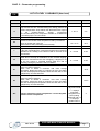
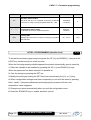
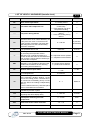
1
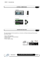
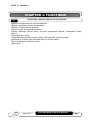
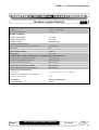
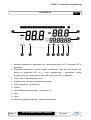
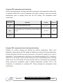
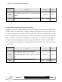
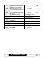
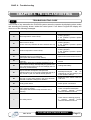
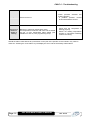
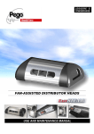
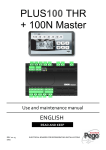
PLUS 100 AB
rev 01-15
Page 2
USE AND MAINTENANCE MANUAL
Rev. 01-15
CONTENTS
INTRODUCTION
Page 4
Page 4
Page 5
Page 5
1.1
1.2
1.3
1.4
General
Product ID codes
Overall dimensions
Identification data
INSTALLATION
Page 6
Page 6
2.1
2.2
Important information for installer
Standard assembly and use kit
FUNCTIONS
Page 7
3.1
Functions managed by the Plus 100 AB
TECHNICAL CHARACTERISTICS
Page 8
Page 9
4.1.
4.2
Technical characteristics
Warranty terms
CHAP. 1
CHAP. 2
CHAP. 3
CHAP. 4
PARAMETER PROGRAMMING
Page 10
Page 11
Page 12
Page 13
Page 13
Page 13
Page 14
Page 18
Page 19
Page 20
Page 21
Page 23
Page 23
Page 23
Page 24
Page 24
Page 24
5.1
5.2
5.3
5.4
5.5
5.6
5.7
5.8
5.9
5.10
5.11
5.12
5.13
5.14
5.15
5.16
5.17
LCD areas
Control panel
LCD display
General features
Key to symbols
Setting and displaying the set-points
Programming the type of work
Level 1 programming
List of Level 1 variables
Level 2 programming
List of Level 2 variables
Switching on the PLUS 100 electronic controller
Compressor activation/deactivation conditions
Cooling cycle activation/deactivation conditions
Manual defrost
Hot gas defrost
Modifying date and time
CHAP. 5
TROUBLESHOOTING
Page 25
6.1
Troubleshooting guide
CHAP. 6
APPENDICES
Page 27
Page 28
A.1
A.2
EC declaration of conformity
PLUS 100 AB connections diagram
Rev. 01-15
USE AND MAINTENANCE MANUAL
Page 3
CHAP. 1 - Introduction
CHAPTER 1: INTRODUCTION
GENERAL
1.1
The electronic controllers of the PLUS 100 series have been designed to control static or
ventilated cold rooms.
The PLUS100 AB electronic board allows the user to control all the components on a
refrigeration unit. The board allows the user to control and power the main refrigeration
system components such as the compressor, evaporator fans, defrosting elements and
room light.
There is also a product cooling function: the cooling can be ended as a function of time or
the temperature of the product skewering sensor.
PRODUCT ID CODES
1.2
PLUS100 AB
Page 4
Controller for cooling and storage rooms.
USE AND MAINTENANCE MANUAL
Rev. 01-15
CHAP. 1 - Introduction
OVERALL DIMENSIONS
1.3
IDENTIFICATION DATA
1.4
The unit described in this manual has, on its side, an ID plate showing all the relevant
identification data:
• Name of Manufacturer
• Code and model of electrical board
• Serial number
• Power supply voltage
Rev. 01-15
USE AND MAINTENANCE MANUAL
Page 5
CHAP. 2 - Installation
CHAPTER 2: INSTALLATION
2.1
IMPORTANT INFORMATION FOR THE INSTALLER
1. Install the device in places where the protection rating is observed and try not to
damage the box when drilling holes for wire/pipe seats.
2. Do not use multi-polar cables in which there are wires connected to inductive/power
loads or signalling wires (e.g. probes/sensors and digital inputs).
3. Do not fit power supply wiring and signal wiring (probes/sensors and digital inputs) in
the same raceways or ducts.
4. Minimise the length of connector wires so that wiring does not twist into a spiral shape
as this could have negative effects on the electronics.
5. Fit a general protection fuse upstream from the electronic controller.
6. All wiring must be of a cross-section suitable for relevant power levels.
7. When it is necessary to make a probe/sensor extension, the wires must be of the
correct cross-section, which in any case must be at least 1 mm2.
2.2
STANDARD ASSEMBLY AND USE KIT
The PLUS 100 AB system is supplied with the following assembly and utilisation items:
• n°1 console fixing bracket
• n°2 temperature sensors (skewering sensor separate)
• n°1 user’s manual
Page 6
USE AND MAINTENANCE MANUAL
Rev. 01-15
CHAP. 3 - Functions
CHAPTER 3: FUNCTIONS
3.1
-
FUNCTIONS CONTROLLED BY THE PLUS100AB -
Display and adjustment of room temperature
Display of skewering sensor temperature
Display of evaporator temperature
System control activation/deactivation
System warnings (sensor error, min-max temperature alarms, compressor safety
device);
Evaporator fan control
Automatic/manual defrost control (static, with elements, cycle inversion)
Switching on of room light with panel key or via door switch
Clock for defrosts in real time clock
Alarm relay
Rev. 01-15
USE AND MAINTENANCE MANUAL
Page 7
CHAP. 4 – Technical characteristics
CHAPTER 4: TECHNICAL CHARACTERISTICS
TECHNICAL CHARACTERISTICS
4.1
Power supply
Voltage
MAX power absorption
230 V~ ± 10% 50Hz
~ 7 VA
Climatic conditions
Working temperature
-10 - 60°C
Storage temperature
-30 - 70°C
Relative humidity
Below RH 90%
General characteristics
Type of sensors that can be connected
NTC 10K 1%
Resolution
1°C
Sensor read precision
± 0.5°C
Read range
-45…+45
PLUS100 AB - Output characteristics - max applicable load (230 V AC)
Compressor (non-powered contact)
1500 W (AC3)
Elements (non-powered contact)
1500 W (AC1)
Fans (non-powered contact)
500 W (AC3)
Room light (non-powered contact)
800 W (AC1)
Alarm contact (non-powered contact)
800 W (AC1)
Dimensional characteristics
Dimensions
19.3 cm x 7.9 cm x 20.3 cm (HxDxL)
Insulation / mechanical characteristics
Box protection rating
IP 65
Box material
ABS self-extinguishing
Type of insulation
Class II
Page 8
USE AND MAINTENANCE MANUAL
Rev. 01-15
CHAP. 4 – Technical characteristics
WARRANTY TERMS
4.2
PLUS 100 electronic controllers are covered by a 24-month warranty against all
manufacturing defects, valid from date of delivery. If the system malfunctions as a result of
tampering, impact or improper installation the warranty will automatically be rendered null
and void. It is strongly recommended that you observe all instructions/information
regarding the technical characteristics of the device.
WARNING !
Any modifications made to wiring and/or internal components or any tasks
carried out in a way that fails to comply with the information/instructions in this
manual shall not only render the warranty null and void immediately but may
also lead to malfunctions, irreparable damage, serious injury or put
persons/objects in danger.
PEGO S.r.l. declines any responsibility for possible errors or inaccuracies
written in this manual as a result of printing or transcription errors.
PEGO S.r.l. reserves the right to modify its products as it deems necessary
without altering its main characteristics. Each new release of a PEGO user
manual replaces previous ones.
Rev. 01-15
USE AND MAINTENANCE MANUAL
Page 9
CHAP. 5 – Parameter programming
CHAPTER 5: PARAMETER PROGRAMMING
LCD AREAS
5.1
1. Display of current month (previous months also remain lit)
2. Indicator/warning LEDs:
a. Cold: cooling in progress
b. Quick freezing: rapid freezing in progress
c. Temperature freezing cooling/freezing by temperature (PR1, PR2, PR3)
d. Time freezing cooling/freezing by time (PR4, PR5, PR6)
Page 10
USE AND MAINTENANCE MANUAL
Rev. 01-15
CHAP. 5 – Parameter programming
CONTROL PANEL
5.2
1.
COOLING CYCLE START key (if pressed for a few seconds the cooling
cycle starts)
2.
UP / MUTE BUZZER ALARM key (if pressed for 5 seconds, together with
key 1, recorded alarms are displayed)
3.
STAND BY key (system shuts down, room temperature light flashes)
4.
SET key, room temperature
5.
DOWN / MANUAL DEFROST key
6.
ROOM LIGHT key
Rev. 01-15
USE AND MAINTENANCE MANUAL
Page 11
CHAP. 5 – Parameter programming
LCD DISPLAY
5.3
1. Ambient temperature / parameters (for values greater than +45°C the word HOT is
displayed).
2. Evaporator temperature / product sensor temperature / day of current month (see
setting on parameter tEu on 1st level programming) / parameters (during
programming) (for values greater than +45°C the word HOT is displayed)
3. Time / date / time parameter values
4. Programming (control is in programming mode)
5. Cold (compressor call indicator)
6. Defrost
7. Fans (flashing during fan stop – parameter F5)
8. Light
9. Alarm
10. Stand-by (flashing in stand-by. Outputs deactivated.)
Page 12
USE AND MAINTENANCE MANUAL
Rev. 01-15
CHAP. 5 – Parameter programming
GENERAL
5.4
To enhance safety and simplify the operator’s work, the PLUS 100 system has two
programming levels; the first level (Level 1) is used to configure the frequently-modified
SET-POINT parameters. The second programming level (Level 2) is for general parameter
programming of the various controller work modes.
It is not possible to access Level 2 programming directly from Level 1: you must exit the
programming mode first.
KEY TO SYMBOLS
5.5
For purposes of practicality the following symbols are used:
• (t) the UP key is used to increase values and mute the buzzer;
• (u) the DOWN key is used to decrease values and force defrosting.
5.6
SETTING AND DISPLAYING THE SET-POINTS
1. Press the SET key to display the current SET-POINT (temperature or humidity).
2. Hold down the SET key and press the (t) or (u) keys to modify the SET-POINT.
3. Release the SET key to return to room temperature display: the new setting will be
saved automatically.
Rev. 01-15
USE AND MAINTENANCE MANUAL
Page 13
CHAP. 5 – Parameter programming
PROGRAMMING THE TYPE OF WORK (User level)
5.7
To gain access to the programs menu it is necessary to:
1. Press the key
2. Use the arrow keys to select the program (PR1....PR6).
3. Press the SET key.
4. After selecting the desired variable it will be possible:
• To modify the setting by holding the SET key pressed and pressing the (t) or (u) keys.
When the modifications have been made press key 1 to return to program selection (at this
point it is possible to modify another program or start the work cycle).
The STAND-BY key allows the user to exit selection and return to manual storage.
Program PR1: temperature-based cooling
Program for product cooling by positive temperature. Cooling ends when the core of the
product reaches temperature At1. A maximum safety time is set on parameter Ab1. When
cooling is over the controller automatically goes to storage mode with the ST1 setting. ST1
also has the function of controlling the compressor, which stops if the room temperature
reaches temperature ST1-r1. The compressor is reactivated on reaching temperature ST1.
VARIABLES
At1
MEANING
End of PR1 cooling temperature
VALUES
DEFAULT
-45 +45 °C
5°C
-45 +45 °C
5°C
0:10:00…10:00:00
4:00:00
Storage temperature at end of cooling / lower
compressor stop limit (- differential r1)
The compressor stops during cooling if the ambient
ST1
temperature drops below ST1-r1. The fans continue to
run
Ab1
Page 14
Maximum safety duration of PR1 cooling
USE AND MAINTENANCE MANUAL
Rev. 01-15
Program PR2: temperature-based freezing
Product freezing program. Freezing ends when the product core temperature reaches At2.
A maximum safety time is set on parameter Ab2. When freezing is over the controller
automatically goes to storage mode with the ST1 setting. The compressor works
continuously.
VARIABLES
At2
MEANING
End of freezing temperature PR2
VALUES
DEFAULT
-45 +45 °C
-20°C
-45 +45 °C
-20°C
0:10:00…10:00:00
4:00:00
Storage temperature setting at end of freezing
The compressor does not stop for the entire duration of
ST2
Ab2
freezing
Maximum safety duration of PR2 freezing
Program PR3: temperature-based cooling and freezing
Program for product cooling and freezing by positive temperature. When room
temperature drops below the STS setting the switch from cooling to freezing takes place.
Freezing continues until the end of the cycle even in the event of a power cut or a rise in
temperature. Freezing ends when the product core reaches temperature At3. A maximum
safety time is set on Ab3. At the end of freezing the control automatically goes to storage
mode as per the ST3 setting. ST3 also has the function of controlling the compressor
during cooling (the compressor stops if ambient temperature reaches ST3-r1). The
compressor is reactivated on reaching ST3. During freezing the compressor works
continuously.
Rev. 01-15
USE AND MAINTENANCE MANUAL
Page 15
CHAP. 5 – Parameter programming
VARIABLES
At3
MEANING
End of PR3 Cooling/Freezing temperature
VALUES
DEFAULT
-45 +45 °C
-20°C
-45 +45 °C
-20°C
0:10:00…10:00:00
0:30:00
Storage temperature at end of cooling-freezing /
lower compressor stop limit (- differential r1).
The compressor stops during cooling if ambient
ST3
temperature drops below ST3-r1. The fans continue to
run
Ab3
Maximum safety duration of PR3 cooling-freezing
Program PR4: time-based cooling
Program for product cooling by time. Cooling ends when the maximum time Ab4 has
expired. When cooling is over the controller automatically goes to storage mode with the
ST4 setting. ST4 also has the function of regulating the compressor, which stops if room
temperature reaches temperature ST4-r1. The compressor is reactivated on reaching
temperature ST4.
VARIABLES
MEANING
VALUES
DEFAULT
-45 +45 °C
5°C
0:10:00…10:00:00
4:00:00
Storage temperature at end of cooling / lower
compressor stop limit (- differential r1)
The compressor stops during cooling if the ambient
ST4
temperature drops below ST4-r1. The fans continue to
run
Ab4
Maximum safety duration of PR4 cooling
Program PR5: time-based freezing
Product freezing program by time. Freezing ends when maximum time Ab5 has expired.
When freezing is over the controller automatically goes to storage mode with the ST5
setting. The compressor works continuously.
Page 16
USE AND MAINTENANCE MANUAL
Rev. 01-15
CHAP. 5 – Parameter programming
VARIABLES
MEANING
VALUES
DEFAULT
-45 +45 °C
-20°C
0:10:00…10:00:00
1:00:00
Storage temperature setting at end of freezing
The compressor does not stop for the entire duration of
ST5
Ab5
freezing
Maximum duration of PR5 freezing
Program PR6: time-based cooling and freezing
Program for product cooling and freezing by time. When room temperature drops below
the STS setting the switch from cooling to freezing takes place. Freezing continues until
the end of the cycle even in the event of a power cut or a rise in temperature. Freezing
ends when the maximum time Ab6 expires. At the end of freezing the control automatically
goes to storage mode as per setting ST6. ST6 also has the function of regulating the
compressor during cooling (the compressor stops if ambient temperature reaches ST6-r1).
The compressor is reactivated on reaching ST6. During freezing the compressor works
continuously.
VARIABLES
MEANING
VALUES
DEFAULT
-45 +45 °C
-20°C
0:10:00…10:00:00
3:00:00
Storage temperature at end of cooling-freezing /
lower compressor stop limit (- differential r1).
The compressor stops during cooling if ambient
ST6
temperature drops below ST6-r1. The fans continue to
run
Ab6
Maximum duration of PR6 cooling-freezing
Rev. 01-15
USE AND MAINTENANCE MANUAL
Page 17
CHAP. 5 – Parameter programming
LEVEL 1 PROGRAMMING (User level)
5.8
To gain access to the Level 1 configuration menu proceed as follows:
1. Press the (t) and (u) keys simultaneously and keep them pressed for a few seconds
until the first programming variable appears on the display.
2. Release the (t) and (u) keys.
3. Select the variable to be modified using the (t) or (u) key.
4. When the variable has been selected it is possible:
• to display the setting by pressing SET
• to modify the setting by pressing the SET key and the (t) or (u) keys.
When configuration values have been set you can exit the menu by pressing the (t) and
(u) keys simultaneously for a few seconds until the room temperature reappears.
5. The new settings are saved automatically when you exit the configuration menu.
Page 18
USE AND MAINTENANCE MANUAL
Rev. 01-15
CHAP. 5 – Parameter programming
5.9
LIST OF LEVEL 1 VARIABLES (User level)
VARIABLE
r0
r1
d0
d2
d3
d7
F5
A1
A2
tEu
MEANING
Temperature differential referred to main SETPOINT
Ambient temperature limit during cooling The compressor
stops and the fans are activated during the cooling phase if the
ambient temperature drops below this differential with respect
to
the
program-specific
storage
temperature
(ST1,ST3,ST4,ST6). The compressor restarts on re-attainment
of the settings (ST1,ST3,ST4,ST6).
Defrost interval (hours)
End-of-defrost setpoint.
Defrost is not executed if the temperature read by the defrost
sensor is greater than value d2
(If the sensor is faulty defrosting is time-based)
Maximum defrost duration (minutes)
Drip duration (minutes)
At the end of defrosting the compressor and the fans remain at
standstill for time setting d7: the defrost LED on the front of the
panel flashes.
Fan pause after defrost (minutes)
Allows fans to be kept at standstill for a time F5 after dripping.
This time is counted from the end of dripping. If dripping is not
set the fan pause is executed directly after the end of
defrosting. During the pause the fan icon flashes.
Minimum temperature alarm
(active only during storage)
Allows user to define a minimum cold room storage
temperature. Below the value A1 a warning is given: the alarm
LED and the displayed temperature flash and the fault is also
highlighted by an internal buzzer.
Maximum temperature alarm
(active only during storage).
Allows user to define a maximum cold room storage
temperature. Above the value A2 a warning is given: the alarm
LED and the displayed temperature flash and the fault is also
highlighted by an internal buzzer.
Displays evaporator sensor temperature / current day-date
/ product sensor temperature
Rev. 01-15
VALUES
DEFAULT
1 - 10 °C
2°C
1 - 50 °C
5°C
0 - 24 hours
4 hours
-35 - 45 °C
10°C
1 - 240 min
25 min
0 - 30 min
0 min
0 - 10 min
0 min
-
-45°C
-
+45°C
0 = displays the
day on the LCD
1 = displays
evaporator
temperature on
LCD (nothing
displayed if dE =1
2 = displays
product sensor
2
USE AND MAINTENANCE MANUAL
Page 19
CHAP. 5 – Parameter programming
VARIABLE
MEANING
VALUES
DEFAULT
dFr
Real-time defrost enable
With d0=0 and dFr=1 it is possible to set up to 6 defrosts
in real time in a day by using the parameters dF1…dF6
0 disabled
1 enabled
0
Programming defrost times
It is possible to set up to 6 defrosting times
00:00:00 23:50:00
--
-45 - +45 °C
-10°C
dF1…dF6
STS
Freezing SET
Manages the switch from cooling to freezing in programs
PR3 and PR6.
LEVEL 2 PROGRAMMING (Installer level)
5.10
To access the second programming level press the UP (t) and DOWN (u) keys and the
LIGHT key simultaneously for a few seconds.
When the first programming variable appears the system automatically goes to stand-by.
1. Select the variable to be modified by pressing the UP (t) and DOWN (u) keys.
When the parameter has been selected it is possible to:
2. View the setting by pressing the SET key.
3. Modify the setting by holding the SET key down and pressing the (t) or (u) key.
4. When configuration settings have been completed you can exit the menu by pressing
the (t) and (u) keys simultaneously and keeping them pressed until the room
temperature value reappears.
5. Changes are saved automatically when you exit the configuration menu.
6. Press the STAND-BY key to enable electronic control.
Page 20
USE AND MAINTENANCE MANUAL
Rev. 01-15
LIST OF LEVEL 2 VARIABLES (Installer level)
VARIABLE
AC
F3
F4
F6
F7
dE
dE1
dC
d1
d4
Ad
Ald
C1
MEANING
Door switch input status
Fan status with compressor off
Fan pause during defrost
5.11
VALUES
0= normally open
1= normally closed
0 = Fans working
continuously
1 = Fans working only when
compressor working
0 = Fans working during
defrost
1 = Fans not working during
defrost
Air re-circulate fan activation
The fans come on for a time defined by F7
if they have not come on for the time F6.
0 – 240 min
If the moment of activation coincides with
defrosting there is a wait until defrosting
has been completed
Air re-circulate fans activation duration
0-240 sec
Fan operation time for F6
Sensor presence
By excluding the evaporator sensor
defrosts occur cyclically according to a
0 = evaporator sensor present
period d0 and end when an external device
1 = evaporator sensor absent
that closes the remote defrost contact trips
or when time d3 expires
Product sensor presence
With dE1=1 it is possible to disconnect the
0 = product sensor present
1 = product sensor absent
product sensor without an error warning
and cooling is time-based only
0 = NO
Remote defrost input status
1 = NC
Defrost type, cycle-inversion (hot gas) or
1= hot gas
by heating element
0= element
End-of-cooling defrost
This parameter decides whether, at the
end of the cooling phase, a defrost has to
be carried out immediately (d4=0) or if the
0–1
defrosts follow the settings independently
(d4=1).
If d4=0 a defrost will in any case take place
even if timed defrosts are enabled
Network address for connection to the
0 - 31
TeleWIN supervision system
Minimum and maximum temperature
1…240 min
signalling and alarm display delay
Minimum time between shutdown and
subsequent switching on of the
0…15 min
compressor.
DEFAULT
0
1
1
0 (function
deactivated)
0:00:10
0
0
0 = NA
0
default 0
0
2:00:00
0 min
CAL
Cold room sensor value correction
-10…+10
0
CAS
Skewer sensor value correction
-10…+10
0
Rev. 01-15
USE AND MAINTENANCE MANUAL
Page 21
CHAP. 5 – Parameter programming
Pc
doC
Fst
Compressor protection contact status
Compressor safety time for door
switch: when the door is opened the
evaporator fans shut down and the
compressor will continue working for time
doC, after which it will shut down.
FAN shutdown TEMPERATURE
The fans will stop if the temperature value
read by the evaporator sensor is higher
than this value.
tA
NO – NC alarm relay switching
rA
Control relay door anti-fogging element
in2
Lic
Upper temperature set-point limit
dMY
Day-month-year setting
hMS
Clock setting
Page 22
0 = NO
0…5 minutes
0
-45…+45°C
+45°C
=activates when alarm is on
1=deactivates when alarm is
on
0=alarm relay
1=anti-fogging element on
Man in cold room alarm
Select input INP2 on the board as end of
remote defrost or as man in cold room
alarm (contact NC).
Lower temperature set-point limit
LSc
0 = NO
1 = NC
USE AND MAINTENANCE MANUAL
1
0
0 = remote defrost end
1 = man in room alarm
0
-45.. LSc
-45°C
Lic..+45
+45°C
day-month-year
-
Hour–min-sec
-
Rev. 01-15
CHAP. 5 – Parameter programming
5.12
SWITCHING ON THE PLUS 100 AB ELECTRONIC CONTROLLER
After wiring the electronic controller correctly, power up at 230 V AC; the display panel will
immediately emit a beep and all the segments and LEDs will come on simultaneously for a
few seconds.
COMPRESSOR ACTIVATION/DEACTIVATION CONDITIONS
5.13
The PLUS 100 controller activates the compressor when cold room temperature exceeds
setting+differential (r0); it deactivates the compressor when cold room temperature is
lower than the setting.
5.14
COOLING AND/OR FREEZING CYCLE ACTIVATION/DEACTIVATION CONDITIONS
To start a program press key 1.
Select a program (PR1....PR6) using the up / down keys.
Start the selected program by pressing key 1 for a few seconds. It is also possible to start
a program starting from stand-by mode.
To confirm the start of a cycle the warning/indicator LEDs come on and the program in use
is displayed. Compressor and fans function as per the settings in the individual programs.
The fans run continuously and the defrosts are inhibited. If key 1 is pressed briefly during
operation the remaining time appears momentarily on the display. At the end of the
program (time or temperature-based, indicated by a buzzer sounding for 30 seconds) the
controller carries out a defrost cycle (d4=0), after which it goes to storage mode and
controls the set room temperature.
To deactivate the cooling cycle manually press key 1 for a few seconds until the indicator
LED goes out.
Rev. 01-15
USE AND MAINTENANCE MANUAL
Page 23
CHAP. 5 - Parameter programming
MANUAL DEFROSTING
5.15
To defrost just press the dedicated key (see section 5.2) to activate the elements relay.
Defrosting will not take place if the end-of-defrost temperature setting (d2) is lower than
the temperature detected by the evaporator sensor. Defrosting ends when the end-ofdefrost temperature (d2) or maximum defrost time (d3) is reached.
HOT GAS DEFROSTING
5.16
Set parameter d1 =1 to manage the defrost cycle in inversion mode.
The compressor relay and defrost relay are activated throughout the defrost phase.
To ensure proper control of the system the installer must use the defrost output: this must
allow opening of the cycle inversion solenoid valve and closure of the liquid solenoid valve.
For capillary systems (without thermostat valve) it is only necessary to control the cycle
inversion solenoid valve via the defrost relay control.
MODIFYING DATE AND TIME
5.17
To change date and time settings just modify the values as per the parameter setting
procedure described in section 5.9 of this manual.
Page 24
USE AND MAINTENANCE MANUAL
Rev. 01-15
CHAP. 6 - Troubleshooting
CHAPTER 6: TROUBLESHOOTING
TROUBLESHOOTING GUIDE
6.1
In the event of any anomalies the PLUS100 system warns the operator by displaying alarm codes
and sounding the warning buzzer inside the control panel. If an alarm is tripped the display will
show one of the following messages.
ALARM CODE
E0
E1
E2
E3
E5
E6
E7
E8
POSSIBLE CAUSE
PROCEDURE TO BE FOLLOWED
• Check that the room sensor is
working properly
Roof temperature sensor faulty
• If the problems persists replace
the sensor
• Check that defrost sensor is
Defrost sensor faulty
working properly
(In this event any defrosts will have duration time d3) • If the problems persists replace
the sensor
• Check that product sensor is
working properly
Product temperature sensor faulty
• If the problems persists replace
the sensor
EEPROM ALARM
EEPROM memory error detected.
• Switch off unit and switch back on
(All outputs deactivated except alarms)
Data write alarm; the controller is not saving data
• Contact
technical
assistance
correctly.
service
Flat battery alarm; the controller will function for at
least another 20 days; subsequently any power loss
• Change the battery
to the board will involve loss of time settings (but not
previously recorded data)
• Switch off unit and switch back on;
Day/month/date anticipation attempt alarm
date/day/month/year
will
be
Happens when you try to bring forward the date by a
restored as per the settings prior
day, month or year or if data is already present.
to the variation attempt.
Man in room alarm
• Reset the alarm switch inside the
The man in room alarm switch in the room has been
cold room
pressed to indicate a dangerous situation
E9
Faulty printer alarm
• Check printer connections
Ec
Compressor safety device tripped (e.g. Overheat or
max. pressure switch.)
(All outputs deactivated except the alarm one, if
present)
• Check the compressor status
• Check compressor absorption
• If
problem
persists contact
technical assistance service
Eu
Fan safety device
Rev. 01-15
• Check fans are working properly
• If
problem
persists contact
technical assistance service
USE AND MAINTENANCE MANUAL
Page 25
CHAP. 6 - Troubleshooting
Ep
Temperature
shown on
display is
flashing
Pressure lock-out
• Check pressure switches are
working properly
• If problem persists contact
technical assistance service
•
Minimum or maximum temperature alarm.
The temperature inside the cold room has exceeded
•
the min. or max. temperature alarm setting (see
variables A1 and A2, user programming level)
Check that the compressor is
working properly.
Sensor not reading temperature
properly or compressor start/stop
control not working.
Should the alarm cease without any intervention on the part of the operator a record shall in any case be
made of it. Pressing the “mute alarm” key will display the error code of the already-ceased alarm.
Page 26
USE AND MAINTENANCE MANUAL
Rev. 01-15
Appendices
APPENDICES
DICH. DI CONFORMITA’ CE / EC DECLARATION OF CONFORMITY
A.1
COSTRUTTORE / MANUFACTURER
PEGO SRL
Via Piacentina,6b
45030 Occhiobello (RO) - ITALY
-
DENOMINAZIONE DEL PRODOTTO / NAME OF THE PRODUCT
MOD.:
PLUS 100 AB
IL PRODOTTO E’ CONFORME ALLE SEGUENTI DIRETTIVE CE/THE PRODUCT IS
IN CONFORMITY WITH THE REQUIREMENTS OF THE FOLLOWING EUROPEAN
DIRECTIVES:
2006/95/CE
2006/95/EC
Direttiva del Consiglio per l’unificazione delle normative dei Paesi CEE relativa al
materiale elettrico destinato ad essere utilizzato entro certi limiti di tensione e
successive modificazioni
EC Directive on unification of laws of the Member States relating to electrical equipment
employed within certain voltage limits and subsequent amendments
89/336 CEE
Direttiva del Consiglio per l’unificazione delle normative dei Paesi CEE relativa
alla compatibilità elettromagnetica e successive modificazioni
89/336 EEC
EC Directive on unification of the laws of the Member States relating to electro-magnetic
compatibility and subsequent amendments
93/68 CEE
Direttiva del consiglio per la marcatura CE del materiale elettrico destinato ad essere
utilizzato entro taluni limiti di tensione.
LA CONFORMITA’ PRESCRITTA DALLE DIRETTIVE E’ GARANTITA DALL’
ADEMPIMENTO A TUTTI GLI EFFETTI DELLE SEGUENTI NORME:
CONFORMITY WITH THE REQUIREMENTS OF THIS DIRECTIVE IS TESTIFIED BY
COMPLETE ADHERENCE TO THE FOLLOWING STANDARDS:
NORME ARMONIZZATE / HARMONIZED EUROPEAN STANDARDS
EN 61000-6-1 EN 61000-6-3 EN 60335 – 1
Rev. 01-15
USE AND MAINTENANCE MANUAL
Page 27
Appendices
A.2
PLUS 100 AB connections diagram
Power section
Outputs (free-voltage contacts)
1-2 Power supply 230VAC 50/60 Hz
15-16
Freezing solenoid
13-14
Cooling solenoid
Analog inputs
11-12 Alarm
27-28 NTC 10K cold room
9-10
Cold room light
29-30 NTC 10K food
7-8
Fans
31-32 NTC 10K evaporator
5-6
Defrost
3-4
Compressor
Digital inputs
41-50 Compressor protection
TeleNET section:
42-50 Switch door
39 A line or clamp 3 TWRS485
43-50 Remote end defrost
40 B line or clamp 4 TWRS485
44-50 Fan overload protection
45-50 Pressure alarm
Nota:
44-50 45-50 stops cold, fans, solenoids. Activates alarm
15-16 Freezing solenoid (active in freezing process)
13-14 Cooling solenoid (active in cooling process and with compressor during manual function)
Page 28
USE AND MAINTENANCE MANUAL
Rev. 01-15
Notes:
Rev. 01-15
USE AND MAINTENANCE MANUAL
Page 29
Page 30
USE AND MAINTENANCE MANUAL
Rev. 01-15
Rev. 01-15
USE AND MAINTENANCE MANUAL
Page 31
PEGO S.r.l.
Via Piacentina, 6/b
Dealer:
45030 OCCHIOBELLO –ROVIGOTel : 0425 762906
Fax: 0425 762905
www.pego.it
USE AND MAINTENANCE MANUAL
Page 32
e-mail: [email protected]
Rev. 01-15