1
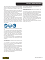
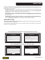
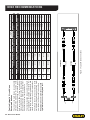
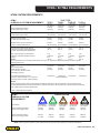
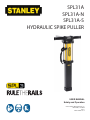
SPL31A SPL31A-N SPL31A-S HYDRAULIC SPIKE PULLER USER MANUAL Safety and Operation © 2013 Stanley Black & Decker, Inc. New Britain, CT 06053 U.S.A. 72925 4/2014 Ver. 7 TABLE OF CONTENTS SAFETY SYMBOLS...................................................................................................................................................4 SAFETY PRECAUTIONS...........................................................................................................................................5 TOOL STICKERS & TAGS.........................................................................................................................................6 HOSE TYPES.............................................................................................................................................................7 HOSE RECOMMENDATIONS...................................................................................................................................8 FIGURE 1. TYPICAL HOSE CONNECTIONS........................................................................................................8 HTMA REQUIREMENTS............................................................................................................................................9 OPERATION.............................................................................................................................................................10 TROUBLESHOOTING............................................................................................................................................. 11 SPECIFICATIONS....................................................................................................................................................12 SPL31A/SPL31A-N/SPL31A-S HANDLE ASSY ILLUSTRATION............................................................................13 SPL31A/SPL31A-N/SPL31A-S PARTS ILLUSTRATION.........................................................................................14 SPL31A/SPL31A-N/SPL31A-S PARTS LIST...........................................................................................................15 IMPORTANT To fill out a Product Warranty Recording form, and for information on your warranty, visit Stanleyhydraulic.com and select the Warranty tab. (NOTE: The warranty recording form must be submitted to validate the warranty). SERVICING: This manual contains safety, operation, and routine maintenance instructions. Stanley Hydraulic Tools recommends that servicing of hydraulic tools, other than routine maintenance, must be performed by an authorized and certified dealer. Please read the following warning. WARNING SERIOUS INJURY OR DEATH COULD RESULT FROM THE IMPROPER REPAIR OR SERVICE OF THIS TOOL. REPAIRS AND / OR SERVICE TO THIS TOOL MUST ONLY BE DONE BY AN AUTHORIZED AND CERTIFIED DEALER. For the nearest authorized and certified dealer, call Stanley Hydraulic Tools at the number listed on the back of this manual and ask for a Customer Service Representative. SPL31 User Manual ◄ 3 SAFETY SYMBOLS Safety symbols and signal words, as shown below, are used to emphasize all operator, maintenance and repair actions which, if not strictly followed, could result in a life-threatening situation, bodily injury or damage to equipment. This is the safety alert symbol. It is used to alert you to potential personal injury hazards. Obey all safety messages that follow this symbol to avoid possible injury or death. DANGER This safety alert and signal word indicate an imminently hazardous situation which, if not avoided, will result in death or serious injury. WARNING This safety alert and signal word indicate a potentially hazardous situation which, if not avoided, could result in death or serious injury. CAUTION This safety alert and signal word indicate a potentially hazardous situation which, if not avoided, could result in death or serious injury. CAUTION This signal word indicates a potentially hazardous situation which, if not avoided, may result in property damage. NOTICE This signal word indicates a situation which, if not avoided, will result in damage to the equipment. IMPORTANT This signal word indicates a situation which, if not avoided, may result in damage to the equipment. Always observe safety symbols. They are included for your safety and for the protection of the tool. LOCAL SAFETY REGULATIONS Enter any local safety regulations here. Keep these instructions in an area accessible to the operator and maintenance personnel. 4 ► SPL31 User Manual SAFETY PRECAUTIONS Tool operators and maintenance personnel must always comply with the safety precautions given in this manual and on the stickers and tags attached to the tool and hose. • Do not operate a damaged, improperly adjusted, or incompletely assembled tool. These safety precautions are given for your safety. Review them carefully before operating the tool and before performing general maintenance or repairs. • Do not weld or cut the chute, handle or jaws of the tool. Supervising personnel should develop additional precautions relating to the specific work area and local safety regulations. If so, place the added precautions in the space provided in this manual. This tool will provide dependable service if operated in accordance with the instructions given in this manual. Read and understand this manual and any stickers and tags attached to the tool and hoses before operation. Failure to do so could result in personal injury or equipment damage. • Never wear loose clothing that can get entangled in the working parts of the tool. • Only use accessories that conform to the specifications given in the OPERATION section of this manual. • To avoid personal injury or equipment damage, all tool repair, maintenance and service must only be performed by authorized and properly trained personnel. • Place the end of the chute squarely against the tie plate, tilting as required to avoid the sudden realignment that can occur as the tool begins to pull. • Always hold the tool with both hands when the unit is running. Use a firm grip. • The operator must start in a work area without bystanders. • Do not operate the tool unless thoroughly trained or under the supervision of an instructor. Establish a training program for all operators to ensure safe operation. • Always wear safety equipment such as goggles, gloves, ear and head protection, and safety shoes at all times when operating the tool. • The operator must be familiar with all prohibited work areas such as excessive slopes and dangerous terrain conditions. • Do not over-reach. Maintain proper footing and balance at all times. • Do not inspect or clean the tool while the hydraulic power source is connected. Accidental engagement of the tool can cause serious injury. • Always connect hoses to the tool hose couplers before energizing the hydraulic power source. Be sure all hose connections are tight and are in good condition. • Do not operate the tool at oil temperatures above 140°F/60°C. Operation at higher temperatures can cause higher then normal temperatures at the tool which can result in operator discomfort. SPL31 User Manual ◄ 5 TOOL STICKERS & TAGS FLOW: 5-10 GPM/19-38 LPM 73019 SPL31A LOGO Decal PRESSURE: MAX 2500 PSI MAX 173 BAR 73020 Flow & Pressure Decal 73037 Pinch Point Warning Decal 14090 Stanley Logo Decal NOTE: THE INFORMATION LISTED ON THE STICKERS SHOWN, MUST BE LEGIBLE AT ALL TIMES. REPLACE DECALS IF THEY BECOME WORN OR DAMAGED. REPLACEMENTS ARE AVAILABLE FROM YOUR LOCAL STANLEY DISTRIBUTOR. The safety tag at right is attached to the tool when shipped from the factory. Read and understand the safety instructions listed on this tag before removal. We suggest you retain this tag and attach it to the tool when not in use. D A N G E R 1. FAILURE TO USE HYDRAULIC HOSE LABELED AND CERTIFIED AS NON-CONDUCTIVE WHEN USING HYDRAULIC TOOLS ON OR NEAR ELECTRICAL LINES MAY RESULT IN DEATH OR SERIOUS INJURY. BEFORE USING HOSE LABELED AND CERTIFIED AS NONCONDUCTIVE ON OR NEAR ELECTRIC LINES BE SURE THE HOSE IS MAINTAINED AS NON-CONDUCTIVE. THE HOSE SHOULD BE REGULARLY TESTED FOR ELECTRIC CURRENT LEAKAGE IN ACCORDANCE WITH YOUR SAFETY DEPARTMENT INSTRUCTIONS. 2. A HYDRAULIC LEAK OR BURST MAY CAUSE OIL INJECTION INTO THE BODY OR CAUSE OTHER SEVERE PERSONAL INJURY. A. DO NOT EXCEED SPECIFIED FLOW AND PRESSURE FOR THIS TOOL. EXCESS FLOW OR PRESSURE MAY CAUSE A LEAK OR BURST. B. DO NOT EXCEED RATED WORKING PRESSURE OF HYDRAULIC HOSE USED WITH THIS TOOL. EXCESS PRESSURE MAY CAUSE A LEAK OR BURST. C. CHECK TOOL HOSE COUPLERS AND CONNECTORS DAILY FOR LEAKS. DO NOT FEEL FOR LEAKS WITH YOUR HANDS. CONTACT WITH A LEAK MAY RESULT IN SEVERE PERSONAL INJURY. D. DO NOT LIFT OR CARRY TOOL BY THE HOSES. DO NOT ABUSE HOSE. DO NOT USE KINKED, TORN OR DAMAGED HOSE. 3. MAKE SURE HYDRAULIC HOSES ARE PROPERLY CONNECTED TO THE TOOL BEFORE PRESSURING SYSTEM. SYSTEM PRESSURE HOSE MUST ALWAYS BE CONNECTED TO TOOL “IN” PORT. SYSTEM RETURN HOSE MUST ALWAYS BE CONNECTED TO TOOL “OUT” PORT. REVERSING CONNECTIONS MAY CAUSE REVERSE TOOL OPERATION WHICH CAN RESULT IN SEVERE PERSONAL INJURY. 4. DO NOT CONNECT OPEN-CENTER TOOLS TO CLOSEDCENTER HYDRAULIC SYSTEMS. THIS MAY RESULT IN LOSS OF OTHER HYDRAULIC FUNCTIONS POWERED BY THE SAME SYSTEM AND/OR SEVERE PERSONAL INJURY. 5. BYSTANDERS MAY BE INJURED IN YOUR WORK AREA. KEEP BYSTANDERS CLEAR OF YOUR WORK AREA. 6. WEAR HEARING, EYE, FOOT, HAND AND HEAD PROTECTION. 7. TO AVOID PERSONAL INJURY OR EQUIPMENT DAMAGE, ALL TOOL REPAIR MAINTENANCE AND SERVICE MUST ONLY BE PERFORMED BY AUTHORIZED AND PROPERLY TRAINED PERSONNEL. I M P O R T A N T I M P O R T A N T READ OPERATION MANUAL AND SAFETY INSTRUCTIONS FOR THIS TOOL BEFORE USING IT. READ OPERATION MANUAL AND SAFETY INSTRUCTIONS FOR THIS TOOL BEFORE USING IT. USE ONLY PARTS AND REPAIR PROCEDURES APPROVED BY STANLEY AND DESCRIBED IN THE OPERATION MANUAL. USE ONLY PARTS AND REPAIR PROCEDURES APPROVED BY STANLEY AND DESCRIBED IN THE OPERATION MANUAL. TAG TO BE REMOVED ONLY BY TOOL OPERATOR. TAG TO BE REMOVED ONLY BY TOOL OPERATOR. SEE OTHER SIDE SEE OTHER SIDE SAFETY TAG (Shown smaller then actual size) 6 ► SPL31 User Manual D A N G E R HOSE TYPES The rated working pressure of the hydraulic hose must be equal to or higher than the relief valve setting on the hydraulic system. There are three types of hydraulic hose that meet this requirement and are authorized for use with Stanley Hydraulic Tools. They are: Certified non-conductive — constructed of thermoplastic or synthetic rubber inner tube, synthetic fiber braid reinforcement, and weather resistant thermoplastic or synthetic rubber cover. Hose labeled certified nonconductive is the only hose authorized for use near electrical conductors. Wire-braided (conductive) — constructed of synthetic rubber inner tube, single or double wire braid reinforcement, and weather resistant synthetic rubber cover. This hose is conductive and must never be used near electrical conductors. Fabric-braided (not certified or labeled non-conductive) — constructed of thermoplastic or synthetic rubber inner tube, synthetic fiber braid reinforcement, and weather resistant thermoplastic or synthetic rubber cover. This hose is not certified non-conductive and must never be used near electrical conductors. HOSE SAFETY TAGS To help ensure your safety, the following DANGER tags are attached to all hose purchased from Stanley Hydraulic Tools. DO NOT REMOVE THESE TAGS. If the information on a tag is illegible because of wear or damage, replace the tag immediately. A new tag may be obtained from your Stanley Distributor. D A N G E R D A N G E R 1. FAILURE TO USE HYDRAULIC HOSE LABELED AND CERTIFIED AS NON-CONDUCTIVE WHEN USING HYDRAULIC TOOLS ON OR NEAR ELECTRIC LINES MAY RESULT IN DEATH OR SERIOUS INJURY. FOR PROPER AND SAFE OPERATION MAKE SURE THAT YOU HAVE BEEN PROPERLY TRAINED IN CORRECT PROCEDURES REQUIRED FOR WORK ON OR AROUND ELECTRIC LINES. 2. BEFORE USING HYDRAULIC HOSE LABELED AND CERTIFIED AS NON-CONDUCTIVE ON OR NEAR ELECTRIC LINES. WIPE THE ENTIRE LENGTH OF THE HOSE AND FITTING WITH A CLEAN DRY ABSORBENT CLOTH TO REMOVE DIRT AND MOISTURE AND TEST HOSE FOR MAXIMUM ALLOWABLE CURRENT LEAKAGE IN ACCORDANCE WITH SAFETY DEPARTMENT INSTRUCTIONS. 3. DO NOT EXCEED HOSE WORKING PRESSURE OR ABUSE HOSE. IMPROPER USE OR HANDLING OF HOSE COULD RESULT IN BURST OR OTHER HOSE FAILURE. KEEP HOSE AS FAR AWAY AS POSSIBLE FROM BODY AND DO NOT PERMIT DIRECT CONTACT DURING USE. CONTACT AT THE BURST CAN CAUSE BODILY INJECTION AND SEVERE PERSONAL INJURY. 4. HANDLE AND ROUTE HOSE CAREFULLY TO AVOID KINKING, ABRASION, CUTTING, OR CONTACT WITH HIGH TEMPERATURE SURFACES. DO NOT USE IF KINKED. DO NOT USE HOSE TO PULL OR LIFT TOOLS, POWER UNITS, ETC. 5. CHECK ENTIRE HOSE FOR CUTS CRACKS LEAKS ABRASIONS, BULGES, OR DAMAGE TO COUPLINGS IF ANY OF THESE CONDITIONS EXIST, REPLACE THE HOSE IMMEDIATELY. NEVER USE TAPE OR ANY DEVICE TO ATTEMPT TO MEND THE HOSE. 6. AFTER EACH USE STORE IN A CLEAN DRY AREA. SEE OTHER SIDE SIDE 1 SEE OTHER SIDE (Shown smaller than actual size) DO NOT REMOVE THIS TAG DO NOT REMOVE THIS TAG THE TAG SHOWN BELOW IS ATTACHED TO “CERTIFIED NON-CONDUCTIVE” HOSE SIDE 2 D A N G E R D A N G E R 1. DO NOT USE THIS HYDRAULIC HOSE ON OR NEAR ELECTRIC LINES. THIS HOSE IS NOT LABELED OR CERTIFIED AS NON-CONDUCTIVE. USING THIS HOSE ON OR NEAR ELECTRICAL LINES MAY RESULT IN DEATH OR SERIOUS INJURY. 5. CHECK ENTIRE HOSE FOR CUTS CRACKS LEAKS ABRASIONS, BULGES, OR DAMAGE TO COUPLINGS IF ANY OF THESE CONDITIONS EXIST, REPLACE THE HOSE IMMEDIATELY. NEVER USE TAPE OR ANY DEVICE TO ATTEMPT TO MEND THE HOSE. 2. FOR PROPER AND SAFE OPERATION MAKE SURE THAT YOU HAVE BEEN PROPERLY TRAINED IN CORRECT PROCEDURES REQUIRED FOR WORK ON OR AROUND ELECTRIC LINES. 6. AFTER EACH USE STORE IN A CLEAN DRY AREA. 3. DO NOT EXCEED HOSE WORKING PRESSURE OR ABUSE HOSE. IMPROPER USE OR HANDLING OF HOSE COULD RESULT IN BURST OR OTHER HOSE FAILURE. KEEP HOSE AS FAR AWAY AS POSSIBLE FROM BODY AND DO NOT PERMIT DIRECT CONTACT DURING USE. CONTACT AT THE BURST CAN CAUSE BODILY INJECTION AND SEVERE PERSONAL INJURY. 4. HANDLE AND ROUTE HOSE CAREFULLY TO AVOID KINKING, CUTTING, OR CONTACT WITH HIGH TEMPERATURE SURFACES. DO NOT USE IF KINKED. DO NOT USE HOSE TO PULL OR LIFT TOOLS, POWER UNITS, ETC. DO NOT REMOVE THIS TAG DO NOT REMOVE THIS TAG THE TAG SHOWN BELOW IS ATTACHED TO “CONDUCTIVE” HOSE. SEE OTHER SIDE SEE OTHER SIDE SIDE 1 SIDE 2 (Shown smaller than actual size) SPL31 User Manual ◄ 7 8 ► SPL31 User Manual All hydraulic hose must meet or exceed specifications as set forth by SAE J517. All hydraulic hose must have at least a rated minimum working pressure equal to the maximum hydraulic system relief valve setting. This chart is intended to be used for hydraulic tool applications only based on Stanley Hydraulic Tools tool operating requirements and should not be used for any other applications. The chart to the right shows recommended minimum hose diameters for various hose lengths based on gallons per minute (gpm)/ liters per minute (lpm). These recommendations are intended to keep return line pressure (back pressure) to a minimum acceptable level to ensure maximum tool performance. Tool to Hydraulic Circuit Hose Recommendations MM Inside Diameter INCH USE (Press/Return) PSI up to 10 up to 3 3/8 10 Both 2250 49-60 49-60 13-16 13-16 FLOW >>> RETURN <<< FLOW PRESSURE 26-100 up to 25 100-200 51-100 up to 50 100-300 51-100 8-30 up to 8 30-60 15-30 up to 15 30-90 15-30 up to 15 7.5-30 up to 7.5 Figure 1. Typical Hose Connections 38-49 10-13 38-49 10-13 38-49 19-40 5-10.5 10-13 19-40 5-10.5 up to 50 26-100 15-23 19-40 4-6 up to 25 15-23 19 19 25.4 16 19 19 25.4 3/4 1 5/8 3/4 3/4 1 16 5/8 3/4 16 19 3/4 5/8 16 16 5/8 13 13 10 5/8 1/2 1/2 3/8 Return Pressure Return Pressure Return Pressure Return Pressure Both Return Pressure Both Both Both Both 2500 2500 2500 2500 2500 2500 2500 2500 2500 2500 2500 2500 2500 2500 2500 175 175 175 175 175 175 175 175 175 175 175 175 175 175 175 155 BAR Min. Working Pressure Certified Non-Conductive Hose - Fiber Braid - for Utility Bucket Trucks METERS Hose Lengths FEET Conductive Hose - Wire Braid or Fiber Braid -DO NOT USE NEAR ELECTRICAL CONDUCTORS 15-34 5-10.5 4-6 4-9 LPM Oil Flow GPM HOSE RECOMMENDATIONS HTMA / EHTMA REQUIREMENTS HTMA / EHTMA REQUIREMENTS HTMA HYDRAULIC SYSTEM REQUIREMENTS TYPE I Nominal Operating Pressure (at the power supply outlet) 4-6 gpm (15-23 lpm) 1500 psi (103 bar) TOOL TYPE TYPE II TYPE RR 7-9 gpm (26-34 lpm) 1500 psi (103 bar) 9-10.5 gpm (34-40 lpm) 1500 psi (103 bar) System relief valve setting (at the power supply outlet) 2100-2250 psi (145-155 bar) 2100-2250 psi (145-155 bar) 2200-2300 psi (152-159 bar) 2100-2250 psi (145-155 bar) Maximum back pressure (at tool end of the return hose) 250 psi (17 bar) 250 psi (17 bar) 250 psi (17 bar) 250 psi (17 bar) Measured at a max. fluid viscosity of: (at min. operating temperature) 400 ssu* 400 ssu* 400 ssu* 400 ssu* (82 centistokes) (82 centistokes) (82 centistokes) (82 centistokes) Temperature: Sufficient heat rejection capacity to limit max. fluid temperature to: (at max. expected ambient temperature) 140° F (60° C) Flow Range 140° F (60° C) 140° F (60° C) TYPE III 11-13 gpm (42-49 lpm) 1500 psi (103 bar) 140° F (60° C) 3 hp 5 hp 6 hp 7 hp Min. cooling capacity at a temperature (2.24 kW) (3.73 kW) (5.22 kW) (4.47 kW) difference of between ambient and fluid 40° F 40° F 40° F 40° F temps (22° C) (22° C) (22° C) (22° C) NOTE: Do not operate the tool at oil temperatures above 140° F (60° C). Operation at higher temperatures can cause operator discomfort at the tool. Filter Min. full-flow filtration Sized for flow of at least: (For cold temp. startup and max. dirt-holding capacity) 25 microns 30 gpm (114 lpm) Hydraulic fluid Petroleum based (premium grade, anti-wear, non-conductive) Viscosity (at min. and max. operating temps) 100-400 ssu* 25 microns 30 gpm (114 lpm) 25 microns 30 gpm (114 lpm) 100-400 ssu* 100-400 ssu* (20-82 centistokes) 25 microns 30 gpm (114 lpm) 100-400 ssu* NOTE: When choosing hydraulic fluid, the expected oil temperature extremes that will be experienced in service determine the most suitable temperature viscosity characteristics. Hydraulic fluids with a viscosity index over 140 will meet the requirements over a wide range of operating temperatures. *SSU = Saybolt Seconds Universal EHTMA HYDRAULIC SYSTEM REQUIREMENTS CLASSIFICATION B C D Nominal Operating Pressure (at the power supply outlet) 3.5-4.3 gpm (13.5-16.5 lpm) 1870 psi (129 bar) 4.7-5.8 gpm (18-22 lpm) 1500 psi (103 bar) 7.1-8.7 gpm (27-33 lpm) 1500 psi (103 bar) 9.5-11.6 gpm (36-44 lpm) 1500 psi (103 bar) 11.8-14.5 gpm (45-55 lpm) 1500 psi (103 bar) System relief valve setting (at the power supply outlet) 2495 psi (172 bar) 2000 psi (138 bar) 2000 psi (138 bar) 2000 psi (138 bar) 2000 psi (138 bar) Flow Range NOTE: These are general hydraulic system requirements. See tool specification page for tool specific requirements SPL31 User Manual ◄ 9 OPERATION CHECK HYDRAULIC POWER SOURCE OPERATING PROCEDURES 1. Using a calibrated flowmeter and pressure gauge, check that the hydraulic power source develops a flow of 5-10.5 gpm/15-40 lpm at 2000 psi/140 bar. 1. Observe all safety precautions. 2. Make certain the hydraulic power source is equipped with a relief valve set to a max of 2500 psi/172 bar. 3. Check that the hydraulic circuit matches the tool for opencenter (OC) operation. CHECK TOOL 1. Make sure all tool accessories are correctly installed. Failure to install tool accessories properly can result in damage to the tool or personal injury. 2. There should be no signs of leaks. 3. The tool should be clean, with all fittings and fasteners tight. CHECK TRIGGER MECHANISM 1. Check that the trigger operates smoothly and is free to travel between the "ON" and "OFF" positions. CONNECT HOSES 1. Wipe all hose couplers with a clean lint-free cloth before making connections. 2. Connect the hoses from the hydraulic power source to the hose couplers on the Spike Puller. It is a good practice to connect the return hose first and disconnect it last to minimize or avoid trapped pressure within the system. 3. Observe flow indicators stamped on hose couplers to be sure that oil will flow in the proper direction. The female coupler is the inlet coupler. NOTE: The pressure increase in uncoupled hoses left in the sun may result in making them difficult to connect. When possible, connect the free ends of operating hoses together. 10 ► SPL31 User Manual 2. Move the hydraulic circuit control valve to the ON position. 3. Place the spike puller firmly over the spike to be pulled making sure the end of the chute is in full contact with the spike plate. SPL31A 1. The SPL31A has an automatic pull cycle that engages the spike and sets the tool to the rail at a slow speed; then fully removes the spike at a higher speed, the cycle is automatic, and operates by fully depressing the trigger. 2. At the top of the stroke release the trigger and the spike will automatically be ejected from the puller. COLD WEATHER OPERATION If the spike puller is to be used during cold weather, preheat the hydraulic fluid at low engine speed. When using the normally recommended fluids, fluid temperature should be at or above 50° F/ 10° C (400 ssu/82 centistokes) before use. TROUBLESHOOTING If symptoms of poor performance develop, the following chart can be used as a guide to correct the problem. When diagnosing faults in operation of the spike puller, always check that the hydraulic power source is supplying the correct hydraulic flow and pressure to the spike driver as listed in the table. Use a flowmeter known to be accurate. Check the flow with the hydraulic oil temperature at least 80 °F/27 °C. Problem Cause Spike puller does not cycle. Spike puller does not pull effectively. Spike puller operates slow. Jaw re-tracked with tool in neutral position Solution Hydraulic power source not functioning correctly. Check power source for proper flow and pressure (5-10 gpm/19-34 lpm, 2500 psi/172 bar. Coupler or hoses blocked. Remove obstruction. Pressure and return line hoses reversed at ports. Be sure hoses are connected to their proper ports. Hydraulic power source not functioning correctly. Check power source for proper flow and pressure (5-10 gpm/19-34 lpm, 2500 psi/172 bar. Couplers or hose blocked. Remove restriction. Fluid too hot (above 140 °F/60 °C). Provide cooler to maintain proper fluid temperature. The jaw is not sliding freely in the chute. Remove, clean and replace as required. Low oil flow from power unit. Check power source for proper flow and oil level. High back pressure. Check hydraulic system for excessive back pressure and correct as required. Couplers or hoses blocked. Remove obstruction. Pressure and return lines reversed at ports. Be sure hoses are connected to their proper ports. NOTICE In addition to the Safety Precautions found in this manual, observe the following for equipment protection and care. • Always store an idle tool in a clean dry space, safe from damage or pilferage. • Be sure to wipe all couplers clean before connecting. Use only lint-free cloths. • Do not exceed the rated limits or use the tool for applications beyond its design capacity. • • Always keep critical tool markings, such as labels and warning stickers legible. • Always replace hoses, couplings and other parts with replacement parts recommended by Stanley Hydraulic Tools. Supply hoses must have a minimum working pressure rating of 2500 psi/175 bar. The hydraulic circuit control valve must be in the OFF position when coupling or uncoupling the tool. Failure to do so may result in damage to the quick couplers and cause overheating of the hydraulic system. • Check fastener tightness often and before each use daily. • Permit only experienced personnel to perform tool repair. SPL31 User Manual ◄ 11 SPECIFICATIONS SPECIFICATIONS Pulling Force...........................................................................................................................................16,647 lbs / 7550 kgPressure ...................................................................................................................................................... 2500 psi/172 bar Maximum Back Pressure .................................................................................................................................250 psi/17 bar Flow Range .......................................................................................................................................... 5-10 gpm / 19-38 lpm HTMA Type I - II, RR Porting ............................................................................................................................................................ -8 SAE O-Ring Couplers ................................................................................................HTMA/EHTMA Flush Face Type Male and Female Connect Size and Type .......................................................................................................................3/8 Male Pipe Adapter Weight (without hose whips & couplers) (with oil) .............................................................................................31 lb / 14.0 kg Overall Length .................................................................................................................................... 32.75 inches / 83.1 cm Overall Handle Width ........................................................................................................................... 16.25 inches / 41.2 cm Overall Height ........................................................................................................................................ 5.25 inches / 13.3 cm Maximum Fluid Temperature................................................................................................................................140° F/60° C ACCESSORIES Hair Pin “W” Grip Jaw (2 Required)...................................................................................................................................34876 12 ► SPL31 User Manual HANDLE ASSEMBLY 5 SPL31A SPL31A-N SPL31A-S 4 15 1 6 2 7 3 17 16 Note: Items 3, 16 and 17 are used on model SPL31A-S and SPL31A-N Only. 14 10 9 12 ITEM * DENOTES PART IN SEAL KIT SEAL KIT 73042 13 11 PART NO. QTY DESCRIPTION 1 1 O-RING* (PART OF SEAL KIT) 2 1 O-RING* (PART OF SEAL KIT) 3 03009 4 21089 5 ROLL PIN (SPL31A-S, SPL31A-N ONLY) 1 ROLL PIN 1 ROD WIPER* (PART OF SEAL KIT) 6 22914 1 SPOOL SEAL CAP 7 22919 1 HEADED TRIGGER 9 35404 1 COMPRESSION COIL SPRING 10 35421 1 COMPRESSION COIL SPRING 11 72888 1 RELIEVING VALVE SPOOL 12 72890 1 RELIEF POPPET 13 73043 1 SPIKE PULLER HANDLE WITH EXPANDER PLUGS INSTALLED 14 73021 1 SAE ORB PLUG MODIFIED 15 73035 1 TRIGGER ANODIZED PAINTED 16 73070 1 SAFETY TRIGGER (SPL31A-S, SPL31A-N ONLY) 17 73171 1 TORSION SPRING (SPL31A-S, SPL31A-N ONLY) SPL31 User Manual ◄ 13 PARTS ILLUSTRATION SPL31A SPL31A-N SPL31A-S SEE PAGE 6 FOR DECAL P/N’s 40 FOR PARTS TO HANDLE ASSEMBLY SEE PAGE 13 31 55 43 PISTON 46 49 39 11 24 33 29 45 4 9 22 50 46 18 36 23 19 4 38 27 24 10 5 10 30 20 3 2 PISTON ROD 37 28 32 44 8 7 14 ► SPL31 User Manual 34 PARTS LIST SPL31A / SPL31A-N / SPL31A-S ITEM P/N. 2 00596 QTY. DESCRIPTION 4 CAPSCREW 1 O-RING* (PART OF SEAL KIT) 2 RETAINING RING 1 O-RING* (PART OF SEAL KIT) 03972 1 COUPLER,FEMALE 3/8NPT FL.FACE SET P/N-03971 (SPL31A AND SPL31A-S ONLY) 47436 1 COUPLER,FEMALE 3/8NPT FL.FACE SET P/N-47438 (SPL31A-N ONLY) 03973 1 COUPLER,MALE 3/8NPT FL.FACE SET P/N-03971 (SPL31A AND SPL31A-S ONLY) 47437 1 COUPLER,MALE 3/8NPT FL.FACE SET P/N-47438 (SPL31A-N ONLY) 9 1 O-RING* (PART OF SEAL KIT) 10 2 BACK-UP RING* (PART OF SEAL KIT) 3 4 00664 5 7 8 11 09275 2 RETAINING RING EXTERNAL 18 25992 1 JAW PIVOT SLEEVE 2 SPRING CUP* (PART OF SEAL KIT) 2 RETAINING RING EXTERNAL 1 ROD WIPER* (PART OF SEAL KIT) 19 20 26812 22 23 32097 1 COMPRESSION COIL SPRING 24 33256 2 GRIP JAW CASTING 27 56725 2 HOSE ASSY (SPL31A and SPL31A-S ONLY) 66727 2 HOSE ASSY (SPL31A-N ONLY) 28 71942 1 CHECK VALVE 29 72537 1 SPL31 AUX HANDLE 30 72538 1 PISTON INSERT 31 72540 4 CAPSCREW 32 73044 1 CHUTE, SUB-ASSY (INCLUDES PAINT & DECALS) 33 72552 1 ALUMINUM WASHER 34 72554 1 EXTERNAL INVERTED RET RING 36 72853 1 JAW PIN 37 72854 1 OIL TUBE ITEM P/N. 38 72883 1 SPL31A ROD ASSEMBLY (INCLUDES ITEM 55 PISTON SEAL) 39 72884 1 LOWER CYLINDER HEAD (INCLUDES BEARING & HELICOILS) 40 73045 1 CYLINDER, SUB-ASSY (INCLUDES PAINT & DECALS) 43 72892 4 WASHER 44 72894 1 COMPRESSION COIL SPRING 45 1 PISTON ROD SEAL* (PART OF SEAL KIT) 46 2 O-RING* (PART OF SEAL KIT) 1 SPIKE PULLER HANDLE WITH EXPANDER PLUGS INSTALLED (SEE PAGE 13 FOR PARTS) 50 1 C SHAFT RINGS* (PART OF SEAL KIT) 55 1 PISTON SEAL* (INCLUDED WITH ITEM 38 AND ALSO PART OF SEAL KIT) 49 73043 QTY. DESCRIPTION * DENOTES PART IN SEAL KIT SEAL KIT 73042 SPL31 User Manual ◄ 15 Stanley Hydraulic Tools 3810 SE Naef Road Milwaukie, Oregon 97267-5698 USA (503) 659-5660 / Fax (503) 652-1780 www.stanleyhydraulic.com