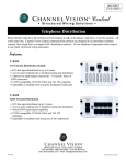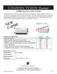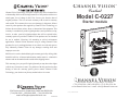
1
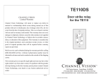
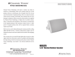
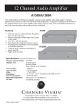
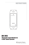
C HANNEL V ISION
Central
1
Channel Vision Technology will repair or replace any defect in material or
workmanship which occurs during normal use of this product with new or
rebuilt parts, free of charge in the USA, for one year from the date of
original purchase. This is a no hassle warranty with no mail in warranty
card needed. This warranty does not cover damages in shipment, failures
caused by other products not supplied by Channel Vision Technology, or
failures due to accident, misuse, abuse, or alteration of the equipment. This
warranty is extended only to the original purchaser, and a purchase receipt,
invoice, or other proof of original purchase date will be required before
warranty repairs are provided. Channel Vision products are not intended
for use in medical, lifesaving, life sustaining or critical environment
applications. Channel Vision customers using or selling Channel Vision
products for use in such applications do so at their own risk and agree to
fully indemnify Channel Vision for any damages resulting from such
improper use or sale.
TM
Model C-0227
Starter module
Mail in service can be obtained during the warranty period by calling (800)
840-0288 toll free. A Return Authorization number must be obtained in
advance and can be marked on the outside of the shipping carton.
This warranty gives you specific legal rights and you may have other rights
(which vary from state to state). If a problem with this product develops
during or after the warranty period, please contact Channel Vision
Technology, your dealer or any factory-authorized service center.
234 FISCHER AVENUE • COSTA MESA, CA 92626
(714) 424-6500 • (800) 840-0288 • (714) 424-6510 fax
www.channelvision.com • email: [email protected]
www.channelvision.com
234 Fischer Avenue, Costa Mesa, California 92626 USA
(714)424-6500 (800)840-0288 (714)424-6510 fax
email: [email protected]
500-305 Rev A
© 2012, CHANNEL VISION™
Model C-0227
Installation Tip
Starter module
ge en
wn
an
e
ro
r
r
B
O
G
striped
solid
2. Use a standard 110 punch tool
Note: Don’t use a screwdriver
as it will damage the connector.
ue
Bl
striped
solid
striped
solid
From
Telephone Company
1. Align cable according to
the color code shown
striped
solid
From
CATV or Antenna
G-Kit 3
(wall plate kit)
Features:
Compact Design
Simple connections
DC power passing 8-way RF splitter
Telephone
Installation:
Telephone distribution to 7 locations
TV
hPunch down as many as 4 incoming telephone lines on
any of the 110 punch down connectors.
hConnect RF signal from your cable company or a rooftop
antenna (see diagram).
hConnect the telephone and RF outputs to wall plates in
each room (see diagram).
Specifications:
RF Insertion loss:
11.5 dB (typical)
RF Bandwidth:
5-1000MHz
RF inputs:
1 (DC passing)
RF outputs:
8 (DC passing)
110 connectors:
8 (all bridged)
Dimensions:
6.50” L x 6.38” W x 2.83” D
hConnect TV and telephone to wall plates.
2
3