1
Model C-0227
Installation Tip
Starter module
ge en
wn
an
e
ro
r
r
B
O
G
striped
solid
2. Use a standard 110 punch tool
Note: Don’t use a screwdriver
as it will damage the connector.
ue
Bl
striped
solid
striped
solid
From
Telephone Company
1. Align cable according to
the color code shown
striped
solid
From
CATV or Antenna
G-Kit 3
(wall plate kit)
Features:
Compact Design
Simple connections
DC power passing 8-way RF splitter
Telephone
Installation:
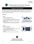
Telephone distribution to 7 locations
TV
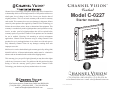
hPunch down as many as 4 incoming telephone lines on
any of the 110 punch down connectors.
hConnect RF signal from your cable company or a rooftop
antenna (see diagram).
hConnect the telephone and RF outputs to wall plates in
each room (see diagram).
Specifications:
RF Insertion loss:
11.5 dB (typical)
RF Bandwidth:
5-1000MHz
RF inputs:
1 (DC passing)
RF outputs:
8 (DC passing)
110 connectors:
8 (all bridged)
Dimensions:
6.50” L x 6.38” W x 2.83” D
hConnect TV and telephone to wall plates.
2
3