1
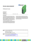
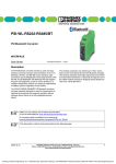
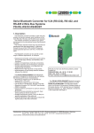
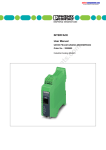
FL BT SPA
Serial Bluetooth adapter for a wireless connection of
a serial interface to a Bluetooth access point
AUTOMATION
Data Sheet
7660_en_01
1
© PHOENIX CONTACT - 04/2008
Description
The FL BLUETOOTH Serial Port Adapter (FL BT SPA) is
serial Bluetooth device that meets industrial needs. The
BT SPA supports Bluetooth specification 2.0. It features a
D-SUB 9 port and a Bluetooth interface.
Features of the wireless interface
–
–
–
–
–
Bluetooth 2.0, HID profile
Frequency range 2.4000 GHz to 2.4835 GHz
ISM band
The maximum emitted transmission power can be set
between 0 dBm/1 mW and 16 dBm/39.8 mW,
automatically controlled
Diagnostic and status indicators
Device properties
–
–
–
–
RS-232 interface (V.24), RS-422, RS-485
Secure data transmission thanks to 128-bit encryption
Support of SPP Bluetooth profile
Configurable range of 0.1 m to 250 m outdoors
–
–
–
–
–
Automatic transmission power control (AFH)
Configuration using Bluetooth and the web-based
management of the FL BT SPA or AT commands
Bluetooth qualified as product (Bluetooth version 2.0)
Wireless LAN co-existence support through channel
skipping and low emission mode
Replaceable antenna
Features and fields of application of the FL BT SPA
–
–
–
–
–
Reliable transmission of serial data in harsh industrial
environments
Parallel operation of multiple wireless cells
Cyclic transmission of serial data
Operation of up to seven FL BT SPAs at a single access
point.
Point-to-point connection of two FL BT SPAs
NOTE: Operation of the wireless system is permitted only when using accessories available from
Phoenix Contact. The use of other accessory components invalidates the approval of operation.
Make sure you always use the latest documentation.
It can be downloaded at www.download.phoenixcontact.com.
A conversion table is available on the Internet at www.download.phoenixcontact.com/general/7000_en_00.pdf.
This data sheet is valid for the products listed on the following page:
FL BT SPA
2
Ordering data
Products
Description
Type
Order No.
Pcs./Pkt.
Serial Bluetooth adapter
FL BT SPA
2884952
1
Factory Line Wireless Bluetooth access point
FL BLUETOOTH AP
2737999
1
DIN rail adapter for mounting the Bluetooth devices on a standard DIN rail
FL BT ADAPTER
2884949
1
Description
Order Designation
Order No.
Pcs./Pkt.
Antenna with omni-directional characteristics
Antenna connection
Gain
Degree of protection
Impedance
Horizontal transmission angle
Vertical transmission angle
RAD-ISM-2400-ANT-OMNI-5-0
2884923
1
SMA connector
5 dBi
IP55
50 Ω
360°
45°
Antenna with omni-directional characteristics and
mounting clamp
Antenna connection
Gain
Degree of protection
Impedance
Horizontal transmission angle
Vertical transmission angle
RAD-ISM-2400-ANT-OMNI-6-0
2885919
1
∅ 48 to 95 mm
N female connector
6 dBi
IP55
50 Ω
360°
30°
Panel antenna with omni-directional characteristics
and mounting clamp
Antenna connection
Gain
Degree of protection
Dimensions (W x H x D)
RAD-ISM-2400-ANT-PAN-8-0
2867610
1
∅ 40 to 60 mm
SMA
8 dBi
IP55
101 x 80 x 20 mm
RAD-ISM-2400-ANT-VAN-3-0-SMA
2885867
1
Mounting support for wall mounting of the OMNI-directional antenna with
protection against vandalism
RAD-ANT-VAN-MKT
2885870
1
Coaxial antenna cable
Connection
Attenuation
Impedance
1m
MCX / SMA
2 dBi
50 Ω
RAD-PIG-EF316-MCX-SMA
2867678
1
Coaxial antenna cable
Connection
Attenuation
Impedance
0.3 m
N female connector/
SMA
1.5 dBi
50 Ω
RAD-PIG-EF316-N-SMA
2867694
1
Adapter N (female) > N (female)
RAD-ADP-N/F-N/F
2867843
1
Adapter SMA (female) > SMA (female)
RAD-ADP-SMA/F-SMA/F
2884541
1
Adapter RSMA (female) > RSMA (female)
RAD-ADP-RSMA/F-RSMA/F
2884538
1
Surge voltage protection - Total surge current (8/20) µs of 20 kA, insertion
attenuation at 2.4 GHz to 2.5 GHz < 0,3 dB, N female connector/N female
connector
CN-UB-280DC-BB
2818850
1
Surge voltage protection - Total surge current (8/20) µs of 20 kA, insertion
attenuation at 2.4 GHz to 2.5 GHz < 0,3 dB, N male connector/N female
connector
CN-UB-280DC-SB
2818148
1
Weather-protection tape - Self-vulcanizing for the protection of adapters,
splitters, and cable connections, watertight
RAD-TAPE-SV-25-10
2885812
1
Accessories
Antenna with omni-directional characteristics
and protection against vandalism
Antenna connection
Gain
Degree of protection
Impedance
Connecting cable length
7660_en_01
SMA connector
3 dBi
IP55
50 Ω
1.5 m
PHOENIX CONTACT
2
FL BT SPA
Accessories
Description
Order Designation
Order No.
Pcs./Pkt.
Antenna cable
Antenna cable, 3 m, SMA (male) > SMA (male)
RAD-CAB-EF142-3M
2884512
1
Antenna cable, 5 m, SMA (male) > SMA (male)
RAD-CAB-EF142-5M
2884525
1
Antenna cable, 3 m, N (male) > N (male)
RAD-CAB-EF393-3M
2867649
1
Antenna cable, 5 m, N (male) > N (male)
RAD-CAB-EF393-5M
2867652
1
Antenna cable, 10 m, N (male) > N (male)
RAD-CAB-EF393-10M
2867665
1
Antenna cable, 15 m, N (male) > N (male)
RAD-CAB-EF393-15M
2885634
1
Pigtail
Pigtail, 1 m, MCX (male) > SMA (male)
RAD-PIG-EF-316-MCX-SMA
2867678
1
Pigtail, 0.5 m, MCX (male) > N (male)
RAD-PIG-EF-316-MCX-N
2867681
1
Pigtail, 0.3 m, N (female) > SMA (male)
RAD-PIG-EF316-N-SMA
2867694
1
Pigtail, 0.5 m, N (female) > N (male)
RAD-PIG-EF316-N-N
2867704
1
1
RAD-PIG-EF316-SMA-SMA
2885618
D-SUB cable as a serial connecting cable
Pigtail, 0.5 m, SMA (male) > SMA (male)
VS-09-DSUB-20-LI-1,0
1656233
1
RS-232 cable, 9-pos. SUB-D female to 9-pos. SUB-D female connector
PSM-KA9SUB9/BB/0,5METER
2708520
1
RS-232 (V.24) null modem connector
PSM-AD-D9-NULLMODEM
2708753
1
Description
Type
Order No.
Pcs./Pkt.
User manual for the FL BLUETOOTH AP
UM EN FL BLUETOOTH AP
2888767
Documentation
3
Technical data
General data
Function
Serial Bluetooth adapter
Housing dimensions (width x height x depth) in mm
80 x 25 x 65
Permissible operating temperature
-30°C to 65°C
Permissible storage temperature
-40°C to 85°C
Degree of protection
IP20, DIN 40050, IEC 60529
Class of protection
IEC 61140
Humidity
Operation
5% to 90%, no condensation
Storage
10% to 95%, no condensation
Air pressure
Operation
79.5 kPa to 108 kPa, 2000 m above sea level
Storage
70 kPa to 108 kPa, 3000 m above sea level
Mounting position
Any position on a flat mounting surface
Connection to protective earth ground
Not required
Weight
95 g, typical
Supply voltage (US1/US2 redundant)
Connection
Via COMBICON; conductor cross section = 2.5 mm2, maximum
Nominal value
24 V DC (SELV)
Permissible voltage ranges
9 V DC to 30 V DC
Typical current consumption on US at 24 V DC
200 mA
Typical power consumption
5W
7660_en_01
PHOENIX CONTACT
3
FL BT SPA
Interfaces
Bluetooth interface
Version
Bluetooth according to IEEE 802.15.1; 2.4 GHz to 1 Mbps
Transmission power
16.9 dBm, maximum, can be automatically controlled or set manually
Receiver sensitivity
-85 dBm
Wireless modules that can be connected
1
Supported profiles
SPP
Bluetooth antenna
Characteristic
Omni-directional antenna (can be replaced)
Gain
0 dBi
Connection
SMA
Bluetooth functions
Function
Bridge, P2P
Configuration
Using web-based management, serial interface or AT commands via
Bluetooth
Security
128-bit data encryption
Serial interface
Version
D-SUB female connector, 9-pos., RS-232, RS-422 and RS-485 (2-wire)
Transmission speed
300 to 921600 baud, with CTS/RTS flow control or without flow control
Maximum serial cable length
3m
Mechanical tests
Shock test according to IEC 60068-2-27
Operation: 25g, 11 ms period,
half-sine shock pulse
Storage/transport: 50g, 11 ms period,
half-sine shock pulse
Vibration resistance according to IEC 60068-2-6
Operation/storage/transport: 5g, 10 - 150 Hz, Criterion 3
Free fall according to IEC 60068-2-32
1m
Approvals
FCC/CFR 47 Part 15, ETS 300 328
Conformance with EMC directives
Noise emission according to EN 55022
Class B
Radio interference field strengths according to EN 55022
Class A
Electrostatic discharge (ESD) according to EN 61000-4-2
Contact discharge: ± 4 kV
Air discharge: ± 8 kV
Electromagnetic fields according to IEC 61000-4-3
10 V/m; Criterion A
Conducted interference
according to IEC 61000-4-6
10 VRMS; Criterion A
Fast transients (burst)
according to IEC 61000-4-4
Data lines: 1 kV; Criterion B
Power supply lines: 0.5 kV; Criterion B
Surge voltages according to IEC 61000-4-5
Data lines: ±1 kV asymmetrical; Criterion B
Power supply lines: ±0.5 kV symmetrical/asymmetrical; Criterion B
Differences between this version and previous versions
Version 00: First version
7660_en_01
PHOENIX CONTACT
4
FL BT SPA
4
Installation of FL BT SPA
A minimum distance of 50 cm between modules must be observed when mounting the FL BT SPAs.
Make sure that the antenna is not directly located in front of a metal surface. This may deteriorate the wireless
features of the antenna in the long term.
4.1
Mounting the FL BT SPA on a flat surface
Mount the FL BT SPA onto a level surface and tighten it by using two screws (e.g., 84-M3 X 25-8.8 cylinder head screws).
For the required drill hole distances, please refer to Figure 1 on page 5.
If the FL BT SPA is assembled in a control cabinet, the antenna must be led outside. For a list of corresponding
accessories, please refer to "Accessories" on page 2.
63 mm
2.480 in.
42 mm
1.654 in.
21 mm
0.827 in.
30 mm
1.181 in.
Drill hole template and housing dimensions
FL BT SPA
LAN
Figure 1
7660_en_01
70 mm
2.756 in.
5 mm
0.197 in.
10 mm
0.394 in.
21 mm
0.827 in.
Bluetooth
5 mm
0.197 in.
FL BT SPA
Bluetooth Serial Port Adapter
Ord No.: 2884952
LAN
42 mm
1.654 in.
Bluetooth Serial Port Adapter
Ord No.: 2884952
Bluetooth
76600001
80 mm
3.150 in.
Housing dimensions and drill hole template for the FL BT SPA in millimeters (inches)
PHOENIX CONTACT
5
FL BT SPA
4.2
DIN-rail mounting/removal of the FL BT SPA
Mount the DIN rail adapter (available as an accessory, see
"Ordering data" on page 2) on the rear of the FL BT SPA.
Make sure the adapter and FL BT SPA are positioned
correctly (see diagram below). To mount the FL BT SPA
place the upper holding keyway on the top edge of the DIN
rail and push on the housing from the top (A). Then push the
bottom edge of the housing towards the DIN rail until the
adapter snaps onto the DIN rail (B).
A
oben
To remove the device push on the housing from the top (A)
and pull the bottom edge away from the DIN rail (B).
B
Figure 2
72810013
DIN rail mounting
A minimum distance of 50 cm between modules must be observed when mounting the FL BT SPAs.
Make sure that the antenna is not directly located in front of a metal surface. This may deteriorate the wireless
features of the antenna in the long term.
7660_en_01
PHOENIX CONTACT
6
FL BT SPA
5
FL BT SPA installation/interfaces
Antenna
Mounting holes
Supply voltage
connection
FL BT SPA
Bluetooth Serial Port Adapter
Ord No.: 2884952
Serial
76600002
Bluetooth
Diagnostic/
status
indicators
Figure 3
–
–
–
–
Serial
interface
V.24
Button
1
Button
2
View and interfaces of the FL BT SPA
Mounting holes
Using these holes, you can install the FL BT SPA on a
level surface using two screws (e.g., 84-M3 X 25-8.8
cylinder head screws) (for drill hole distance, see
Figure 1 on page 5).
Antenna
The device is supplied with a 0 dB omni-directional
antenna. You can exchange the supplied antenna for a
different antenna in compliance with the national
regulations.
Supply voltage connection
The supply voltage is connected using the 2-pos.
COMBICON connector.
Button 1 is used to reset the settings for the serial
interface, pressing buttons 1 and 2 resets the device to
the default settings.
–
Status and diagnostic indicators
The LEDs display the status of the serial and Bluetooth
interfaces.
Please note that the depth of the two buttons in
the housing is different.
–
Serial interface - V.24
V.24 (RS-232) interface in D-SUB format (9-pos.).
7660_en_01
PHOENIX CONTACT
7
FL BT SPA
6
Connecting the 24 V DC supply voltage
The FL BT SPA is operated with a 24 V DC voltage. The
FL BT SPA has an internal protection against polarity
reversal.
- +
24 V DC
76600003
Figure 4
7
Supply of the FL BT SPA
Status and diagnostic indicators
There are three LEDs on the front of the device that display
different states.
FL BLUETOOTH AP
Bluetooth Access Point
Ord No.: 27 37 999
Des.
)))
(LED 1)
Color
Status
Blue/
ON (blue)
red/
green/
orange/ Flashing blue
violet
1
2
3
Meaning
Further device
connected with access
point (blue)
Bluetooth data
transmission
Flashing red Faulty data or data rate
Green
LAN
Red
Configuration mode
Violet
Bluetooth
Device in data mode, no
connection at present
Bluetooth connection
establishment
76600004
LED 2
Figure 5
7660_en_01
LEDs on the device front
LED 3
No function
Yellow
ON
Transmission/reception
of serial data
OFF
No transmission/
reception of serial data
PHOENIX CONTACT
8
FL BT SPA
8
V.24 (RS-232) interface
The maximum length of the serial cables is 3 m.
8.1
Assignment of the D-SUB female connector as RS-232 interface
Pin assignment of the serial interface with RS-232
5
1
6
6
Pin 1: Not used
Frontseite
Frontside
Partie front.
Lato front.
Cara frontal
Pin 2: RD (Receive Data), input
Pin 3: TD (Transmit Data), output
Pin 4: DTR (Data Terminal Ready), output
Pin 5: GND
Figure 6
Assignment of the serial interface
Pin 6: DSR (Data Set Ready), input
Pin 7: RTS (Request To Send), output
Pin 8: CTS (Clear To Send), input
Pin 9: Not used
RD Pin 2
TD Pin 3
DTR Pin 4
GND Pin 5
DSR Pin 6
RTS Pin 7
CTS Pin 8
Figure 7
RD Pin 2
TD Pin 3
DTR Pin 4
GND Pin 5
DSR Pin 6
RTS Pin 7
CTS Pin 8
Host System (DTE)
FL BT SPA (DTE)
Assignment of crossover cables (null-modem cable)
Assignment of a crossover cable
RD Pin 2
TD Pin 3
DTR Pin 4
GND Pin 5
DSR Pin 6
RTS Pin 7
CTS Pin 8
Figure 8
7660_en_01
RD Pin 2
TD Pin 3
DTR Pin 4
GND Pin 5
DSR Pin 6
RTS Pin 7
CTS Pin 8
Host System (DTE)
FL BT SPA (DTE)
Assignment of 1:1 cables
Assignment of 1:1 cables
PHOENIX CONTACT
9
FL BT SPA
8.2
Assignment of the D-SUB female connector as an RS-422 interface
For third-party manufacturers the definition of the R+/R- and T+/T- signals can differ.
1
5
6
6
Figure 9
Frontseite
Frontside
Partie front.
Lato front.
Cara frontal
Assignment of the serial interface
Pin assignment of the serial interface with RS-422
Pin 1: R- (Receiver), input
Pin 2: T- (Transmitter), output
Pin 3: Not used
Pin 4: Not used
Pin 5: Not used
Pin 6: R+ (Receiver), input
Pin 7: Not used
Pin 8: T+ (Transmitter), output
Pin 9: Not used
8.3
Assignment of the D-SUB female connector as an RS-485 interface
For third-party manufacturers the definition of the R+/R- and T+/T- signals can differ.
Pin assignment of the serial interface with RS-485
5
1
6
6
Frontseite
Frontside
Partie front.
Lato front.
Cara frontal
Pin 1: R- (Receiver), input
Pin 2: T- (Transmitter), output
Pin 3: Not used
Pin 4: Not used
Pin 5: Not used
Figure 10
Assignment of the serial interface
Pin 6: R+ (Receiver), input
Pin 7: Not used
Pin 8: T+ (Transmitter), output
Pin 9: Not used
When the interface is used as a RS-485 interface the signals/pins T+ (pin 8) and R+ (pin 6) as well as T- (pin 2)
and R- (pin 1) must be generated to generate the signals T+/R+ and T-/R-.
9
Configuration
9.1
Resetting the V.24 (RS-232) interface to default settings
At the bottom of the device there are two buttons next to the
serial interface. Keep button 1 pressed during power-up to
reset the device to its default settings.
9.2
Resetting the entire device to default settings
At the bottom of the device there are two buttons next to the
serial interface. Keep button 1 and button 2 pressed during
power-up to reset the device to its default settings.
7660_en_01
PHOENIX CONTACT
10
FL BT SPA
9.3
Configuration using the web interface or AT commands
The FL BT SPA can be configured together with an FL BLUETOOTH AP via a serial port using its web interface or a special
software. AT command can be used for configuration in both cases.
The software as well as a Quick Start Guide are available for download at www.download.phoenixcontact.com.
For a list with AT commands that can be used, please refer to www.download.phoenixcontact.com.
9.4
Configuration via the web interface of the FL BLUETOOTH AP
To configure the FL BT SPA, select the "SPA" profile on the "Connections" website in the web-based management (WBM)
of the FL BLUETOOTH AP.
For further information on the configuration of the FL BLUETOOTH AP, please refer to the
UM EN FL BLUETOOTH AP user manual, which can be downloaded at www.download.phoenixcontact.com.
Figure 11
7660_en_01
"Connections" website for the FL BLUETOOTH AP
PHOENIX CONTACT
11
FL BT SPA
After you have selected "SPA" under "Profile", simply click the "Configure" button to open the following website.
Figure 12
9.5
1.
2.
9.6
SPA configuration in the WBM of the FL BLUETOOTH AP
How to proceed during configuration
Click the "Enter AT mode" button. "OK" appears at the
bottom part of the window.
Afterwards click the "Read" button. Then the device
reads the data and fields such as "Baud Rate" or
"Parity" are filled.
3.
4.
Now select the desired configuration.
Click the "Write" button to transmit the configuration to
the device.
Configuration using the Bluetooth dongle
A Quick Start Guide can be downloaded at www.download.phoenixcontact.com.
9.7
Configuration of the RS-232 interface using the software tool
A Quick Start Guide can be downloaded at www.download.phoenixcontact.com.
7660_en_01
PHOENIX CONTACT GmbH & Co. KG • 32823 Blomberg • Germany • Phone: +49-(0) 5235-3-00
PHOENIX CONTACT • P.O.Box 4100 • Harrisburg • PA 17111-0100 • USA • Phone: +717-944-1300
www.phoenixcontact.com
12