1
INTERFACE
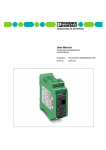
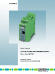
User Manual
m
UM EN PSI-DATA/BASIC-MODEM/RS232
co
Order No.: 2888699
on
l
in
ec
om
po
ne
nt
s.
Industrial Analog Modem
s.
nt
ne
po
om
in
ec
on
l
co
m
INTERFACE
User Manual
08/2006
nt
s.
co
m
Industrial Analog Modem
UM EN PSI-DATA/BASIC-MODEM/RS232
Revision:
01
Order No.:
2888699
Designation
om
in
ec
This user manual is valid for:
po
ne
Designation:
2313067
on
l
PSI-DATA/BASIC-MODEM/RS232
Order No.
102906_01_en
PHOENIX CONTACT
PSI-DATA/BASIC-MODEM/RS232
Please Observe the Following Notes
In order to ensure the safe use of the product described, we recommend that you read this
manual carefully. The following notes provide information on how to use this manual.
User Group of This Manual
m
The use of products described in this manual is oriented exclusively to
– qualified electricians or persons instructed by them, who are familiar with applicable
standards and other regulations regarding electrical engineering and, in particular, the
relevant safety concepts.
– qualified application programmers and software engineers, who are familiar with the
safety concepts of automation technology and applicable standards.
s.
co
Phoenix Contact accepts no liability for erroneous handling or damage to products from
Phoenix Contact or third-party products resulting from disregard of information contained
in this manual.
Explanation of Symbols Used
ne
nt
The attention symbol refers to an operating procedure which, if not carefully followed, could
result in damage to hardware and software or personal injury.
po
The note symbol informs you of conditions that must strictly be observed to achieve
error-free operation. It also gives you tips and advice on the efficient use of hardware
and on software optimization to save you extra work.
om
The text symbol refers to detailed sources of information (manuals, data sheets, literature,
etc.) on the subject matter, product, etc. This text also provides helpful information for the
orientation in the manual.
We Are Interested in Your Opinion
in
ec
We are constantly striving to improve the quality of our manuals.
on
l
Should you have any suggestions or recommendations for improvement of the contents
and layout of our manuals, please send us your comments.
PHOENIX CONTACT
PHOENIX CONTACT GmbH & Co. KG
Documentation Services
32823 Blomberg
Germany
Phone
Fax
E-mail
+49 - 52 35 - 30 0
+49 - 52 35 - 34 20 21
[email protected]
102906_01_en
PSI-DATA/BASIC-MODEM/RS232
General Terms and Conditions of Use for Technical Documentation
Phoenix Contact GmbH & Co. KG reserves the right to alter, correct, and/or improve the
technical documentation and the products described in the technical documentation at its
own discretion and without giving any notice.
The provision of technical documentation (in particular data sheets, installation
instructions, manuals, etc.) does not constitute any further duty on the part of
Phoenix Contact GmbH & Co. KG to furnish information on alterations to products and/or
technical documentation. Any other agreement shall only apply if expressly confirmed in
writing by Phoenix Contact GmbH & Co. KG. Please note that the supplied documentation
is product-specific documentation only.
s.
co
m
Although Phoenix Contact GmbH & Co. KG makes every effort to ensure that the
information content is accurate, up-to-date, and state-of-the-art, technical inaccuracies
and/or printing errors in the information cannot be ruled out.
Phoenix Contact GmbH & Co. KG does not offer any guarantees as to the reliability,
accuracy or completeness of the information provided. Phoenix Contact GmbH & Co. KG
accepts no liability or responsibility for errors or omissions in the content of the technical
documentation (in particular data sheets, installation instructions, manuals, etc.).
on
l
in
ec
om
po
ne
nt
As far as is permissible by applicable jurisdiction, no guarantee or claim for liability for
defects whatsoever shall be granted in conjunction with the information available in the
technical documentation, whether expressly mentioned or implied. This information does
not include any guarantees on quality, does not describe any fair marketable quality and
does not make any claims as to quality guarantees or guarantees on the suitability for a
special purpose.
Phoenix Contact GmbH & Co. KG reserves the right to alter, correct, and/or improve the
information and the products described in the information at its own discretion and without
giving any notice.
102906_01_en
PHOENIX CONTACT
PSI-DATA/BASIC-MODEM/RS232
Statement of Legal Authority
This manual, including all illustrations contained herein, is copyright protected. Use of this
manual by any third party is forbidden. Reproduction, translation, or electronic and
photographic archiving or alteration requires the express written consent
of Phoenix Contact. Violators are liable for damages.
Phoenix Contact reserves the right to make any technical changes that serve the purpose
of technical progress.
Phoenix Contact reserves all rights in the case of patent award or listing of a registered
design. Third-party products are always named without reference to patent rights. The
existence of such rights shall not be excluded.
m
Windows 3.x, Windows 95, Windows 98, Windows NT, Windows 2000, Windows XP, and
MS DOS are trademarks of the Microsoft Corporation.
co
All other product names used are trademarks of the respective organizations.
Internet
s.
Up-to-date information on Phoenix Contact products can be found on the Internet at:
nt
www.phoenixcontact.com
ne
Make sure you always use the latest documentation.
It can be downloaded at:
www.download.phoenixcontact.com
po
A conversion table is available on the Internet at:
om
www.download.phoenixcontact.com/general/7000_en_00.pdf
PSI Hotline
in
ec
Should problems occur that cannot be solved with the help of this documentation, please
contact our hotline:
+ 49 - (0) 52 35 - 3-19 89 0
+ 49 - (0) 52 35 - 3-19 89 9
on
l
[email protected]
PHOENIX CONTACT
102906_01_en
Table of Contents
1
1.1
Short Description................................................................................................ 1-1
1.2
Application.......................................................................................................... 1-2
1.3
Ordering Data..................................................................................................... 1-3
1.4
Technical Data ................................................................................................... 1-3
Quick Startup of a Dial-Up Line Connection............................................................................2-1
2.1
Hardware Installation ......................................................................................... 2-1
2.1.1
Default Configuration .......................................................................... 2-1
2.1.2
Mounting ............................................................................................. 2-1
2.1.3
V.24 (RS-232) Interface ...................................................................... 2-2
2.1.4
Connecting the Telecommunications Cable ....................................... 2-3
2.1.5
Supply Voltage ................................................................................... 2-3
2.2
Software Installation........................................................................................... 2-4
2.2.1
System Requirements ........................................................................ 2-4
2.2.2
Driver Installation ................................................................................ 2-4
ne
Hardware Installation...............................................................................................................3-1
3.1
Structure............................................................................................................. 3-1
3.2
Operating Elements ........................................................................................... 3-2
3.2.1
Connection Terminal Blocks ............................................................... 3-2
3.2.2
Connectors ......................................................................................... 3-2
3.2.3
LEDs ................................................................................................... 3-3
5
Software Installation ................................................................................................................4-1
on
l
4
Electrical Connections........................................................................................ 3-3
3.3.1
Block Diagram .................................................................................... 3-4
3.3.2
V.24 (RS-232) Interface ...................................................................... 3-5
3.3.3
Telecommunications Cable ................................................................ 3-6
3.3.4
Supply Voltage ................................................................................... 3-7
in
ec
3.3
om
po
3
nt
s.
co
m
2
PSI-DATA/BASIC-MODEM/RS232 Industrial Modem.............................................................1-1
4.1
System Requirements ........................................................................................ 4-1
4.2
Driver Installation ............................................................................................... 4-1
4.3
Configuration Software....................................................................................... 4-5
4.3.1
Installation .......................................................................................... 4-5
4.3.2
Operation ............................................................................................ 4-9
Password Protection................................................................................................................5-1
102906_01_en
5.1
Selecting a Password......................................................................................... 5-1
5.2
Deactivating Password Protection ..................................................................... 5-1
5.3
Password-Protected Callback ............................................................................ 5-2
5.4
Dial In With Password Protection ....................................................................... 5-2
PHOENIX CONTACT
i
PSI-DATA/BASIC-MODEM/RS232
6.1
Command Descriptions...................................................................................... 6-2
6.2
AT Commands for MNP and LAPM (V.42bis) .................................................... 6-9
6.3
S Registers.......................................................................................................6-11
6.4
Modulation Commands .................................................................................... 6-17
6.5
Modem Confirmations ......................................................................................6-18
6.6
Processing the Break Character ......................................................................6-20
m
Configuration Help...................................................................................................................7-1
7.1
Programming Connection for Phoenix Contact Controllers................................ 7-1
7.2
Programming Connection for Siemens S7 300/400 ........................................... 7-3
on
l
in
ec
om
po
ne
nt
s.
7
AT Commands.........................................................................................................................6-1
co
6
ii
PHOENIX CONTACT
102906_01_en
PSI-DATA/BASIC-MODEM/RS232 Industrial Modem
1
PSI-DATA/BASIC-MODEM/RS232 Industrial Modem
1.1
Short Description
m
The DIN rail-mountable PSI-DATA/BASIC-MODEM/RS232 V.24 (RS-232) modem is
specifically designed to meet industrial requirements for remote monitoring. It provides
access to machines and systems anywhere in the world via dial-up line connections
according to the V.34 standard. A wide range of security functions, such as connection
establishment with password protection and callback function, protect the system against
unauthorized access.
co
To ensure error-free operation even in harsh EMC conditions, the device has high-quality
3-way isolation and integrated surge protection. The modem also features an integrated
automatic "Sleep" function to increase battery life and a wide supply voltage range of 10 V
to 30 V, making it suitable for universal use.
nt
s.
Modem startup is very easy using plug and play and user-friendly configuration software.
The modem is approved for use in public telephone networks in Europe, the USA, and
Canada. Additional approvals can be provided on request.
om
po
For universal use
Password-protected access/callback function
Wide supply voltage range of 10 V to 30 V DC
Power-saving sleep mode
High-quality three-way isolation (VCC // V.24 (RS-232) // PTSN)
Slim design width of 22.5 mm
Easy startup using plug and play and user-friendly configuration software
3964R-compatible
on
l
in
ec
–
–
–
–
–
–
–
–
ne
Features
102906_01_en
PHOENIX CONTACT
1-1
PSI-DATA/BASIC-MODEM/RS232
1.2
Application
The PSI-DATA/BASIC-MODEM/RS232 modem is suitable for universal and international
use as an analog dial-up modem.
PSI-DATA/BASIC/
MODEM/RS232
Ord.-No. 23 13 067
LINE
OH
DTR
DCD
AA
PSI-DATA/BASIC/
MODEM/RS232
Ord.-No. 23 13 067
LINE
OH
m
RS 232
Telephone
network
DTR
DCD
AA
RS 232
co
PSI-DATA/BASIC/
MODEM/RS232
Ord.-No. 23 13 067
LINE
OH
Dial-up operation
102906A001
ne
Figure 1-1
nt
RS 232
s.
DTR
DCD
AA
om
po
The following modem applications can be implemented:
– Remote monitoring of systems and machines
– Remote control
– Remote system diagnostics
– Production data acquisition
on
l
in
ec
This device is approved for operation in the following public telephone networks:
– Austria
– Belgium
– Canada
– Denmark
– Finland
– France
– Germany
– Great Britain
– Greece
– Ireland
– Italy
– Luxembourg
– Norway
– Portugal
– Spain
– Sweden
– Switzerland
– The Netherlands
– USA
Approvals for other countries are available on request.
1-2
PHOENIX CONTACT
102906_01_en
PSI-DATA/BASIC-MODEM/RS232 Industrial Modem
1.3
Ordering Data
Modem
Description
Industrial analog modem for mounting on EN DIN rails
Scope of supply: Modem, CD with configuration software, manual, and
RJ12/RJ12 cable
Accessories
Description
System power supply unit,
primary-switched
Input voltage range
Nominal output voltage
Nominal output current
Type
Order No.
Pcs./Pck.
PSI-DATA/BASIC-MODEM/RS232
2313067
1
Type
Order No.
Pcs./Pck.
MINI-SYS-PS-100-240AC/24DC/1.5
2866983
1
m
45 Hz ... 65 Hz
85 V AC ... 264 V AC
24 V DC ±1%
1.5 A
ME 22,5 TBUS 1,5/ 5-ST-3,81 GN
2707437
50
9-pos. D-SUB/
9-pos. D-SUB
(female/female)
PSM-KA9SUB9/BB/2METER
2799474
1
V.24 (RS-232) cable, 0.5 m, to connect the modem
to a 9-pos. device interface
9-pos. D-SUB/
9-pos. D-SUB
(female/female)
PSM-KA9SUB9/BB/0,5METER
2708520
1
s.
nt
ne
Technical Data
po
1.4
co
DIN rail connector, to supply power to the modem via the DIN rail bus
V.24 (RS-232) cable, 2 m, to connect the modem to
a 9-pos. device interface
Power Supply
10 V DC ... 30 V DC via COMBICON plug-in screw terminal
Frequency
Current consumption
Nominal operation
Sleep mode (can be configured via software)
in
ec
Display
om
Supply voltage
DC
< 100 mA (at 24 V)
< 40 mA (at 24 V)
Green LED (VCC), steady light during operation
V.24 (RS-232) Interface
Device type
on
l
Connection
9-pos. D-SUB pin strip
Data Communication Equipment (DCE)
Data format/encoding
Serial asynchronous UART/NRZ, 7/8 data,
1/2 stop, 1 parity, 10/11 bits character length
Data flow control/protocols
Software handshake Xon/Xoff,
hardware handshake RTS/CTS
or 3964R
Serial transmission speed
Automatic transmission speed detection for 300, 1200, 2400, 4800, 9600,
19200, 38400, 57600, 115200 bps
Data indicator
Green LED (TD), data to modem (dynamic)
Yellow LED (RD), data from modem (dynamic)
Control signal indicator
Yellow DTR LED, Data Terminal Ready
Yellow DCD LED, Data Carrier Detect
102906_01_en
PHOENIX CONTACT
1-3
PSI-DATA/BASIC-MODEM/RS232
PSTN Port (a/b Line)
Connection
6-pos. RJ12
Shield
Via metal foot on EN DIN rail
Operating modes
Dial-up modem, 2-wire half/full duplex
Dialing procedure
Multiple frequency/pulse dialing, configuration via software
Transmission speed
Automatic adjustment according to V.8
DCE/DCE
300 baud ... 56 kbaud
Fax
2400 baud ... 14.4 kbaud
ITU V.42bis, V.42, V.92, V.90, V.34 extended, ITU V.32bis, V.32, V.21,
V.22bis, V.22, V.23, ITU V.17
Command set compatibility
AT standard command set and extended
V.250 basic command set
Error correction
V.42 (LAPM or MNP 2 to 4)
Data compression
V.42bis (throughput 4:1), MNP 5 (throughput 2:1)
Data indicator
Green LED (OH), off the hook
Acoustic signal
Integrated piezo
Startup diagnostics
Selftest, visualization via LEDs (controller, RAM, EEPROM, DSP)
Telecommunications approvals
TBR21, TIA-968-A, CS-03 for Europe, USA, and Canada
co
m
Compatibility
ne
nt
s.
Yellow LED (AA), automatic answer, flashes during selective call acceptance
Telephone Number Memory
4 telephone numbers with a maximum of 36 digits
po
Telephone number memory
Tests/Approvals
om
UL
General Data
in
ec
Telecommunications
In preparation
TBR21, TIA-968-A, CS-03 for Europe, USA, and Canada
Ambient temperature range (operation)
0°C ... +55°C
Housing
ME 22,5 with T-BUS and ground contact
Material
on
l
Dimensions (H x W x D)
Weight
ABS-V0, green
99 mm x 22.5 mm x 114.5 mm
165 g
Functional earth ground
To EN DIN rail in the housing
Vibration resistance
5g according to DIN EN 60068-2-6, 1.5 h each in x, y, and z direction
Shock test according to IEC 60068-2-27
Operation
Storage
15g, 11 ms, half-sine shock pulse
30g, 11 ms, half-sine shock pulse
Free fall according to IEC 60068-2-32
1m
Degree of protection
IP20
3-way electrical isolation
Supply // PSTN // V.24 (RS-232)
Test voltage
1.5 kV AC, 50 Hz, 1 min. between all ground levels according to
EN 61010-1/VDE 0411-1 and EN 60950
1-4
PHOENIX CONTACT
102906_01_en
PSI-DATA/BASIC-MODEM/RS232 Industrial Modem
Conformance With EMC Directive 89/336/EEC
Noise Immunity Test According to EN 61000-6-21
Electrostatic discharge (ESD)
EN 61000-4-2
Criterion B2
Electromagnetic HF field
EN 61000-4-3
Criterion A3
8 kV air discharge
6 kV contact discharge
10 V/m
10 V/m
Amplitude modulation
Pulse modulation
Fast transients (burst)
EN 61000-4-4
Signal
Criterion B2
2 kV/5 kHz
1 kV/5 kHz
Supply
Criterion A3
2 kV/5 kHz
Surge current load
Criterion B2
EN 61000-4-5
Signal
m
1 kV
Supply
2 kV
Criterion A3
EN 61000-4-6
Noise Emission Test According to EN 61000-6-4
Noise emission of housing
10 V
co
Conducted interference
EN 55022
Limiting curve B
EN 61000 corresponds to IEC 61000
2
Criterion B: Temporary adverse effects on the operating behavior, which the device corrects automatically.
3
Criterion A: Normal operating behavior within the specified limits.
on
l
in
ec
om
po
ne
nt
s.
1
102906_01_en
PHOENIX CONTACT
1-5
on
l
in
ec
om
po
ne
nt
s.
co
m
PSI-DATA/BASIC-MODEM/RS232
1-6
PHOENIX CONTACT
102906_01_en
Quick Startup of a Dial-Up Line Connection
2
Quick Startup of a Dial-Up Line Connection
Quick startup refers only to a standard dial-up connection.
2.1
Hardware Installation
Default Configuration
m
2.1.1
s.
Mounting
nt
2.1.2
co
The modem is preconfigured to dial-up line operation with automatic data rate detection
and automatic call acceptance by default upon delivery.
Mount the modem on a 35 mm EN DIN rail (see Figure 2-1).
po
•
ne
Only mount devices when the power supply is disconnected.
on
l
in
ec
om
The DIN rail must be connected to PE to ensure safe operation.
102906A002
Figure 2-1
102906_01_en
Mounting
PHOENIX CONTACT
2-1
PSI-DATA/BASIC-MODEM/RS232
Electrical connection
Only qualified personnel may connect the power, start up, and operate this device.
According to the safety instructions in this text, qualified personnel are persons who are
authorized to start up, to ground, and to mark devices, systems, and equipment
according to the standards of safety technology. In addition, these persons must be
familiar with all warning instructions and maintenance measures in this text.
Disregarding this warning may result in damage to equipment and/or serious personal
injury.
V.24 (RS-232) Interface
m
2.1.3
s.
co
The modem and the computer or another device are connected via the
PSM-KA-9SUB9/BB/... V.24 (RS-232) cable (see Section 1.3, "Ordering Data").
The cable is an interface cable with 1:1 connected contacts.
Use this interface cable to connect the modem to a free COM interface on the PC.
ne
•
nt
The modem may only be connected to devices, which meet the requirements of
EN 60950 ("Safety of Information Technology Devices").
P C /P L C
D
8
D
2
9
D
1
3
3
3
4
S
R
5
2 0
6
R I
G N D
2 2
7
on
l
in
ec
S
2-2
PHOENIX CONTACT
R
S U B D 9
1
om
D C
T x
R x
R T
C T
D T
D S
D
M o d e m
po
S U B
2 5
M a x .1 5 m
(4 9 .2 1 ft.)
2
2
7
7
8
4
6
6
9
9
5
5
8
4
D C
T x
R x
R T
C T
D T
D S
D
D
D
S
S
R
R
R I
G N D
6 9 2 3 A 0 3 5
Figure 2-2
V.24 (RS-232) interface
102906_01_en
Quick Startup of a Dial-Up Line Connection
2.1.4
Connect the telecommunications cable to an RJ12/RJ11 connector on the front of the
device. Signals "a" and "b" are assigned to the middle pins, 3 and 4.
P in 8
P i n 76
b T2 D -
P i n 65
b n .c .
P i n 54
a n .c .
P i n 43
aT 2 D +
P i n 32
n R . cD . -
P i n 21
R D +
P in 1
6 9 2 3 A 0 3 6
Connection using an RJ12/RJ11 connector
Supply Voltage
nt
2.1.5
co
Figure 2-3
R RJ 4 J 5 1 2
m
n .c .
n n . c . c. .
s.
RJ12/RJ11 connector
Connecting the Telecommunications Cable
ne
The PSI-DATA/BASIC-MODEM/RS232 is designed exclusively for SELV operation
according to IEC 60950/EN 60950/VDE 0805.
0V
24V 0V NC NC
on
l
in
ec
om
24 V
po
Connect the 24 V supply voltage to the "24V" and "0V" terminal points on the plug-in screw
terminal block.
102906A003
Figure 2-4
Connecting the supply voltage
As soon as the "VCC" LED lights up, the modem is ready for dial-up line operation.
102906_01_en
PHOENIX CONTACT
2-3
PSI-DATA/BASIC-MODEM/RS232
2.2
Software Installation
2.2.1
System Requirements
In principle, any device can be connected to the modem via a free V.24 (RS-232) interface.
A terminal program, for example, can be used for configuration. More detailed information
can be found in later sections.
A PC with one of the following operating systems is required for the PSI-MODEM-CONF
configuration software and the plug and play function:
m
Windows 95, Windows 98, Windows 2000, Windows NT, Windows ME or Windows XP.
Connect the modem to the PC as described above and switch on the supply voltage.
After the PC has been started, the modem is detected automatically and the driver can
be installed:
on
l
in
ec
om
po
ne
•
Driver Installation
nt
2.2.2
s.
co
The installation procedure for the driver varies depending on the operating system. In the
following, driver installation under Windows XP is described as an example. During
installation, please always follow the on-screen instructions.
•
2-4
PHOENIX CONTACT
Select "No, not this time" and click "Next".
102906_01_en
ne
Insert the "PSI-MODEM-CONF" CD provided in the drive.
Select "Install the software automatically (Recommended)" and click "Next".
on
l
in
ec
om
po
•
•
nt
s.
co
m
Quick Startup of a Dial-Up Line Connection
•
102906_01_en
Click on "Continue Anyway". Contrary to the message displayed, this will in no way
affect the operation of the software or your computer.
PHOENIX CONTACT
2-5
PSI-DATA/BASIC-MODEM/RS232
Insert the "PSI-MODEM-CONF" CD in the corresponding drive and confirm with "OK".
•
Select "Browse".
on
l
in
ec
om
po
ne
nt
s.
co
m
•
•
2-6
PHOENIX CONTACT
Click on "acfva.sys" and confirm your selection with "Open".
102906_01_en
Confirm with "OK".
on
l
in
ec
om
po
ne
nt
s.
co
•
m
Quick Startup of a Dial-Up Line Connection
102906_01_en
•
Click "Finish" to complete the installation.
The driver has now been installed and the modem is available to application programs,
e.g., the dial-up network.
PHOENIX CONTACT
2-7
on
l
in
ec
om
po
ne
nt
s.
co
m
PSI-DATA/BASIC-MODEM/RS232
2-8
PHOENIX CONTACT
102906_01_en
Hardware Installation
3
Hardware Installation
3.1
Structure
Dimensions
22.5
PSI-DATA/BASIC/
MODEM/RS232
Ord.-No. 23 13 067
co
100
LINE
m
114.5
OH
102906A004
Dimensions (in mm)
ne
Figure 3-1
nt
RS 232
s.
DTR
DCD
AA
Mount the modem on a 35 mm EN DIN rail (see Figure 3-2).
om
•
po
Only mount devices when the power supply is disconnected.
on
l
in
ec
The DIN rail must be connected to PE to ensure safe operation.
102906A002
Figure 3-2
102906_01_en
Mounting
PHOENIX CONTACT
3-1
PSI-DATA/BASIC-MODEM/RS232
3.2
Operating Elements
1
3
2
m
PSI-DATA/BASIC/
MODEM/RS232
Ord.-No. 23 13 067
13
12
11
5
s.
OH
on
l
102906A005
Operating elements
om
in
ec
3.2.1
po
RS 232
Figure 3-3
ne
nt
DTR
DCD
AA
6
PHOENIX CONTACT
co
LINE
10
9
8
7
3-2
4
Connection Terminal Blocks
1
24 V supply (10 V DC ... 30 V DC)
2
0 V supply (0 V)
3
Not used
4
Not used
3.2.2
Connectors
5
Line, RJ12 (telecommunications connection)
6
V.24 (RS-232) data interface, 9-pos. D-SUB
102906_01_en
Hardware Installation
3.2.3
LEDs
AA
(Yellow) Automatic answer (automatic call acceptance), flashes during
selective call acceptance
8
DCD
(Yellow) Data carrier detected, connection established with partner
9
DTR
(Yellow) Connected device is ready (e.g., PC or PLC)
10
OH
(Green)
Off the hook
11
TD
(Green)
Transmit data with reference to the PSTN (telecommunications)
connection
12
RD
(Yellow) Receive data with reference to the PSTN (telecommunications)
connection
13
VCC
(Green)
co
s.
Electrical Connections
nt
3.3
Supply voltage is present
m
7
Electrical connection
po
ne
Only qualified personnel may connect the power, start up, and operate this device.
According to the safety instructions in this text, qualified personnel are persons who are
authorized to start up, to ground, and to mark devices, systems, and equipment
according to the standards of safety technology. In addition, these persons must be
familiar with all warning instructions and maintenance measures in this text.
on
l
in
ec
om
Disregarding this warning may result in damage to equipment and/or serious personal
injury.
102906_01_en
PHOENIX CONTACT
3-3
PSI-DATA/BASIC-MODEM/RS232
3.3.1
Block Diagram
COMBICON
24 V
0V
5V
24 V
s.
co
Backplane
nt
EEPROM
a2
a
µC
b
po
b2
Backplane
D9-SUB
1 DCD
3 TxD
2 RxD
7 RTS
8 CTS RS-232
6 DSR
4 DTR
9 RI
5 GND
on
l
in
ec
om
RJ12
ne
Phone Line
Pin 2
Pin 3
Pin 4
Pin 5
+
m
-
3-4
PHOENIX CONTACT
102906A006
Figure 3-4
Block diagram
102906_01_en
Hardware Installation
3.3.2
V.24 (RS-232) Interface
The modem and the computer or another device are connected via the
PSM-KA-9SUB9/BB/... V.24 (RS-232) cable (see Section 1.3, "Ordering Data").
The cable is an interface cable with 1:1 connected contacts.
•
Use the interface cable to connect the modem to a free COM interface on the PC.
m
In rare cases, when connecting a PLC or control system, DCE (Data Communication
Equipment) may be used instead of DTE (Data Terminal Equipment), which is typical for a
PC. If so, the following cables must be crossed (null modem cable):
– TxD and RxD
– RTS and CTS
– DSR and DTR
The minimum configuration only requires one connection for TxD, RxD, and GND
(software handshake).
s.
Minimum configuration
co
If you do not know which type of interface is connected, you can determine the correct
configuration by testing (crossing cables).
nt
This does not apply to the 3964R protocol for Phoenix Contact controller boards. Only TxD,
RxD, and GND are connected here, but no handshake protocol is selected.
po
P C /P L C
ne
The modem may only be connected to devices, which meet the requirements of
EN 60950 ("Safety of Information Technology Devices").
om
S U B
2 5
D
D
on
l
D
9
S U B D 9
1
1
2
3
3
3
2
2
S
4
7
S
5
8
R
M o d e m
8
D
in
ec
D C
T x
R x
R T
C T
D T
D S
M a x .1 5 m
(4 9 .2 1 ft.)
7
2 0
6
4
4
R
6
6
R I
G N D
2 2
7
9
9
5
5
8
D C
T x
R x
R T
C T
D T
D S
D
D
D
S
S
R
R
R I
G N D
6 9 2 3 A 0 3 5
Figure 3-5
102906_01_en
V.24 (RS-232) interface
PHOENIX CONTACT
3-5
PSI-DATA/BASIC-MODEM/RS232
Table 3-1
Meaning of the terminal designations
Meaning
DCD (Data Carrier Detect)
Data carrier detected, connection established
TxD (Transmit Data)
Transmit data (refers to PC, PLC, etc.)
RxD (Receive Data)
Receive data (refers to PC, PLC, etc.)
RTS (Request To Send)
Request to send
CTS (Clear To Send)
Clear to send
DTR (Data Terminal Ready)
Ready (PC, PLC, etc.)
DSR (Data Set Ready)
Ready (modem)
RI (Ring Indicator)
Incoming call
GND (Signal Ground)
Signal ground
co
Telecommunications Cable
nt
s.
3.3.3
m
Designation
P in 8
P i n 76
b T2 D -
P i n 65
b n .c .
P i n 54
a n .c .
P i n 43
aT 2 D +
n R . cD . -
P i n 32
P i n 21
P in 1
in
ec
R D +
R RJ 4 J 5 1 2
po
n .c .
n n . c . c. .
ne
Connect the telecommunications cable to an RJ12/RJ11 connector on the front of the
device. Signals "a" and "b" are assigned to the middle pins, 3 and 4.
om
RJ12/RJ11 connector
6 9 2 3 A 0 3 6
Connection using an RJ12/RJ11 connector
on
l
Figure 3-6
3-6
PHOENIX CONTACT
102906_01_en
Hardware Installation
3.3.4
Supply Voltage
The PSI-DATA/BASIC-MODEM/RS232 is designed exclusively for SELV operation
according to IEC 60950/EN 60950/VDE 0805.
The supply voltage must be between 10 V and 30 V DC.
Connect the 24 V supply voltage to the "24V" and "0V" terminal points on the plug-in screw
terminal block.
0V
co
m
24 V
102906A003
Connections
om
Figure 3-7
po
ne
nt
s.
24V 0V NC NC
on
l
in
ec
As soon as the "VCC" LED lights up, the modem is ready.
102906_01_en
PHOENIX CONTACT
3-7
on
l
in
ec
om
po
ne
nt
s.
co
m
PSI-DATA/BASIC-MODEM/RS232
3-8
PHOENIX CONTACT
102906_01_en
Software Installation
4
Software Installation
4.1
System Requirements
In principle, any device can be connected to the modem via a free V.24 (RS-232) interface.
A terminal program, for example, can be used for configuration. More detailed information
can be found in later sections.
A PC with one of the following operating systems is required for the PSI-MODEM-CONF
configuration software and the plug and play function:
m
Windows 95, Windows 98, Windows 2000, Windows NT, Windows ME or Windows XP.
ne
Connect the modem to the PC as described above and switch on the supply voltage.
After the PC has been started, the modem is detected automatically and the driver can
be installed:
on
l
in
ec
om
po
•
Driver Installation
nt
4.2
s.
co
The installation procedure for the driver varies depending on the operating system. In the
following, driver installation under Windows XP is described as an example. During
installation, please always follow the on-screen instructions.
•
102906_01_en
Select "No, not this time" and click "Next".
PHOENIX CONTACT
4-1
ne
Insert the "PSI-MODEM-CONF" CD provided in the drive.
Select "Install the software automatically (Recommended)" and click "Next".
on
l
in
ec
om
po
•
•
nt
s.
co
m
PSI-DATA/BASIC-MODEM/RS232
•
4-2
PHOENIX CONTACT
Click on "Continue Anyway". Contrary to the message displayed, this will in no way
affect the operation of the software or your computer.
102906_01_en
Software Installation
Insert the "PSI-MODEM-CONF" CD in the corresponding drive and confirm with "OK".
•
Select "Browse".
on
l
in
ec
om
po
ne
nt
s.
co
m
•
•
102906_01_en
Click on "acfva.sys" and confirm your selection with "Open".
PHOENIX CONTACT
4-3
Confirm with "OK".
on
l
in
ec
om
po
ne
nt
s.
co
•
m
PSI-DATA/BASIC-MODEM/RS232
4-4
PHOENIX CONTACT
•
Click "Finish" to complete the installation.
The driver has now been installed and the modem is available to application programs,
e.g., the dial-up network.
102906_01_en
Software Installation
4.3
Configuration Software
The PSI-MODEM-CONF software is used to configure the PSI-DATA/BASIC-MODEM/
RS232. Your modem has more functions than can be mapped in the configuration
software. To use these functions, enter additional AT commands in the "Additional
Settings" field (see page 4-15). The AT commands and their meanings are described in
"Command Descriptions" on page 6-2.
4.3.1
m
Insert the CD labeled "PSI-MODEM-CONF" in the CD-ROM drive on your computer.
Use Windows Explorer to start the "Setup_Vx.x.xxx.exe" file located in the
"...:\PSI-CONF" directory.
co
•
•
Installation
on
l
in
ec
om
po
ne
nt
s.
Starting installation
102906_01_en
•
Close all other applications and click "Next".
PHOENIX CONTACT
4-5
PSI-DATA/BASIC-MODEM/RS232
Read the terms of the software license agreement thoroughly and click "Yes" to accept
them.
ne
•
nt
s.
co
m
Accepting the terms of the
license agreement
You may now select a specific installation folder.
po
The default setting is "C:\Program Files\PSI-MODEM-CONF".
on
l
in
ec
om
Selecting an installation
folder
•
4-6
PHOENIX CONTACT
If necessary, select a different folder and click "Next".
102906_01_en
Software Installation
For full installation, select "Yes" for both options.
Experienced users can select "No" so that no shortcuts are created on the desktop or
in the Start menu.
ne
•
•
nt
s.
co
m
Selecting
shortcuts
on
l
in
ec
om
po
Start copying
•
102906_01_en
Click "Next" to start copying the files. This may take a few seconds depending on the
system.
PHOENIX CONTACT
4-7
PSI-DATA/BASIC-MODEM/RS232
Exit setup by clicking "Finish".
on
l
in
ec
om
po
ne
•
nt
s.
co
m
Finishing installation
4-8
PHOENIX CONTACT
102906_01_en
Software Installation
4.3.2
Operation
After installation the following shortcut will appear on your desktop:
Double-click on this icon to start the PSI-MODEM-CONF configuration software.
in
ec
om
po
ne
nt
s.
co
m
Starting the software
PSI-MODEM-CONF configuration software
on
l
Figure 4-1
102906_01_en
PHOENIX CONTACT
4-9
PSI-DATA/BASIC-MODEM/RS232
You can set the language to English or German in the "Options" menu item.
Select language
on
l
in
ec
om
Figure 4-2
po
ne
nt
s.
co
m
Select language
4-10
PHOENIX CONTACT
102906_01_en
Software Installation
First, you must configure the interface.
•
Select the "RS232" function in the "Options" menu.
•
Select the interface to which your modem is connected.
s.
co
m
Configuring the interface
Adjust the parameters according to your application requirements.
Apply the settings by confirming with "OK".
•
Click on the "Write" button
to write the settings to the modem.
on
l
in
ec
om
po
ne
nt
•
•
102906_01_en
PHOENIX CONTACT
4-11
PSI-DATA/BASIC-MODEM/RS232
Click on the "Read" button
to read data from the connected modem.
om
po
ne
nt
s.
co
m
•
on
l
in
ec
The software displays the modem type and firmware version.
4-12
PHOENIX CONTACT
102906_01_en
Software Installation
File Functions
Creates a new project file with the default settings.
Opens a saved project file.
Click on the "Settings" button
.
s.
Configuration Profile
co
m
Saves the current settings.
on
l
in
ec
om
po
ne
nt
This opens the "Basic Modem Configuration" window.
Figure 4-3
102906_01_en
"Basic Modem Configuration" window
PHOENIX CONTACT
4-13
PSI-DATA/BASIC-MODEM/RS232
If the echo is on, all characters sent by the computer in command mode are sent back by
the modem. The characters can thus be displayed on screen on the computer.
DCD Signal
When the partner carrier detect signal is detected, the V.24 (RS-232) interface activates
the DCD signal (Data Carrier Detect). Alternatively, this signal can also be permanently
switched on.
DSR Signal
The DSR signal (Data Set Ready) of the V.24 (RS-232) interface can be permanently
switched on or switched off in command mode.
DTR Signal
Your modem can process the DTR signal (Data Terminal Ready) as follows:
– The modem returns to command mode if there is no DTR signal at the V.24 (RS-232)
interface.
– The modem hangs up and returns to command mode if there is no DTR signal at the
V.24 (RS-232) interface.
– The modem hangs up, is reset, and returns to command mode if there is no DTR signal
at the V.24 (RS-232) interface.
– The modem ignores the DTR signal. This may be necessary when using a PLC, as the
V.24 (RS-232) interface of a PLC is often unable to provide a DTR signal.
Flow Control
The data flow control of the V.24 (RS-232) interface can be set for various operating
modes:
– For the "Hardware" setting, the CTS and RTS signals are used for bidirectional data
flow control.
– For the "Software" setting, the data flow control is bidirectional using XON and XOFF
characters.
– In "XON/XOFF Unidirect" mode, the XON character is sent to the computer (DTE) to
start data transmission and the XOFF character is sent to stop data transmission. The
PSI-DATA/FAX-MODEM/RS232 ignores XON and XOFF characters sent by the
computer.
– Data flow control can also be switched off completely. This may be necessary when
protocols such as 3964R are transmitted, which control the flow independently.
on
l
Error Correction
in
ec
om
po
ne
nt
s.
co
m
Echo
When error correction is switched on, any transmission errors are corrected automatically
by the modem. For this, error correction must be activated on the transmitting and
receiving modem. Some protocols, such as 3964R, must not be transmitted with error
correction.
Compression
Data compression on the telecommunications cable results in increased data throughput.
For this, data compression must be activated on the transmitting and receiving modem.
Some protocols, such as 3964R, must not be transmitted with data compression.
Modulation Method
You can specify the transmission method of your modem (default: CCITT).
Table 6-1 on page 6-17 shows how the various settings work.
4-14
PHOENIX CONTACT
102906_01_en
Software Installation
Result Codes
Your modem is configured so that it outputs alphanumeric responses on the screen. The
"Numeric" option can be used if your software package or PLC only supports numeric
confirmations. The relevant settings can be found in Table 6-2 on page 6-18.
Auto Answer
Automatic call acceptance enables you to specify the number of rings after which your
modem can automatically respond to incoming calls. Automatic call acceptance is
switched off by default upon delivery. Active automatic call acceptance is indicated by the
yellow "AA" (Automatic Answer) LED.
This LED flashes in the event of an incoming call, regardless of the automatic call
acceptance setting.
When dial tone detection is switched on the modem waits for the dial tone before dialing.
Dial tone detection should be switched off in a private branch exchange.
Country Code
Select the country where you wish to use your PSI-DATA/FAX-MODEM/RS232. If your
country is not listed, select Europe (CTR21) or the USA.
Speaker
The internal speaker can be switched off, always on or only switched on when establishing
a connection.
Additional Settings (AT)
Your modem has more functions than can be mapped in the configuration software. To use
these functions, enter additional AT commands in the "Additional Settings" field.
The AT commands and their meanings are described in "Command Descriptions" on
page 6-2.
ne
nt
s.
co
m
Dialtone Detection
po
Example: Entering L3 increases the speaker volume.
om
Additional settings can be saved in the project file via the "Save" button. However, they
are not read from the modem by the configuration software.
You can store three telephone numbers in Store Numbers 1 through 3, which can be used
as a speed dial memory. The use of stored telephone numbers with the DS=n command
is described on page 6-4.
on
l
in
ec
Telephone Book
102906_01_en
PHOENIX CONTACT
4-15
PSI-DATA/BASIC-MODEM/RS232
Remote Login
Password Mode
When password mode is active, the caller must enter a password after the incoming call
has been accepted. If the password is invalid or the time allocated for password entry has
been exceeded, the caller has two more attempts to enter the correct password. When the
correct password is entered, the modem continues to operate as usual, otherwise the
connection is aborted.
When password mode is active with callback the caller is requested to enter a password.
If the password is invalid or the time allocated for password entry has been exceeded, the
caller has two more attempts to enter the correct password.
m
When the correct password is entered, the modem aborts the existing connection to dial
the number that is stored in the memory under Callback No. The modem has three
attempts to establish a connection with the callback number.
co
Automatic call acceptance must be activated for all password-protected functions.
s.
Password
Enter your password here.
po
Click on the "Write" button
all been entered.
to write the settings to the modem once they have
on
l
in
ec
om
•
ne
nt
The password can contain up to seven characters from the ASCII character set (1 to
127), excluding question marks. The password is not case-sensitive.
4-16
PHOENIX CONTACT
102906_01_en
Password Protection
5
Password Protection
This section describes password protection using AT commands. For information about
password protection using the PSI-MODEM-CONF configuration software, refer to
page 4-16.
5.1
Selecting a Password
m
The password can contain up to seven characters from the ASCII character set (1 to
127), excluding question marks. The password is not case-sensitive.
s.
co
If no password is stored, the modem continues to request the stored telephone details.
The password and telephone number can be stored using the *P=x and &Zn=x
commands (see below).
nt
Example
Load default setting
AT*P=ASDFG1
Enter the password "ASDFG1"
AT&Z0=012345
Enter the callback number
AT%S1
Activate password protection with callback
po
ATS0=1
Enable automatic call acceptance
*P=x command
om
–
ne
AT&F
Store a password in the permanent memory
in
ec
The *P=x command stores the password x (maximum of seven characters from the ASCII
character set, excluding question marks) in the permanent memory on the modem. No
password is stored on the modem by default. If no password is stored and the %S1 or %S2
command is activated, the modem skips the password request stage.
on
l
–
*P? command
Display stored password
The *P? command displays the stored password.
Your modem has a built-in security function, which can be activated when your modem is
in auto answer mode (see page 6-12).
5.2
Deactivating Password Protection
The %S0 command deactivates password-protected callback (see "Password-Protected
Callback" on page 5-2). By default upon delivery, password protection is deactivated.
102906_01_en
PHOENIX CONTACT
5-1
PSI-DATA/BASIC-MODEM/RS232
5.3
Password-Protected Callback
The %S1 command activates password-protected callback. If you wish to activate this
function, switch your modem to auto answer mode (automatic call acceptance; ATS0 > 0).
Your modem now accepts calls and executes the usual handshake. The caller is then
requested to enter a password. If the password is invalid or the time allocated for password
entry has been exceeded, the caller has two more attempts to enter the correct password.
Dial In With Password Protection
co
5.4
m
When the correct password is entered, the modem aborts the existing connection to dial
the number that is stored in the memory under &Z0. The modem has three attempts to
establish a connection with the callback number.
nt
s.
The %S2 command enables password validation when an incoming called is accepted. In
this case, the caller must enter a password after the incoming call has been accepted. If
the password is invalid or the time allocated for password entry has been exceeded, the
caller has two more attempts to enter the correct password. When the correct password is
entered, the modem continues to operate as usual, otherwise the connection is aborted.
on
l
in
ec
om
po
ne
Automatic call acceptance must be activated for all password-protected functions (see
"S Registers" on page 6-11).
5-2
PHOENIX CONTACT
102906_01_en
AT Commands
6
AT Commands
Your modem stores its operating characteristics in a non-volatile memory (EEPROM). You
can overwrite these characteristics using commands and can thus modify the method of
operation of the device. The modem executes commands as long as it is in command
mode. Your modem is automatically in command mode until you dial a number and
establish a connection. You can enter commands for your modem using appropriate
communication software (e.g., HyperTerminal). The device supports data transmission
speeds of 300, 1200, 2400, 4800, 9600, 19,200, 38,400, 57,600, and 115,200 bps.
m
Make sure that the baud rate setting for your COM port in your communication software
corresponds to one of these speeds.
co
Modes
nt
s.
The modem can be operated in two modes:
– Command mode: The modem can be configured and controlled via AT commands.
As soon as a connection is established, the modem automatically switches to data
mode.
– Data mode: In this mode, the modem transmits data to the partner.
ne
Command Structure
po
All commands transmitted to the modem must start with AT and must be confirmed by
pressing ENTER. The commands can be entered in either upper or lowercase, but not a
mixture of the two. Spaces may be inserted between the commands so that the command
lines are easier to read.
om
AT deletes the last command line executed by your modem (if present) and prepares
your modem for the new command line. In addition, AT informs your modem of the
transmission speed, parity, and character length.
in
ec
For commands that must be specified by a parameter, a missing parameter corresponds
to parameter 0, e.g., ATM = ATM0.
on
l
Correct a Typing Error
102906_01_en
If you make a mistake when entering a command, you can correct it using the backspace
key. Pressing the backspace key deletes the last character entered. The AT at the start of
the command line is not deleted.
Repeat the Previous Command
You can instruct your modem to repeat the previous command by entering A/ in command
mode. AT is not entered for this command and it does not have to be confirmed by pressing
ENTER, i.e., the command is repeated as soon as A/ is entered.
PHOENIX CONTACT
6-1
PSI-DATA/BASIC-MODEM/RS232
6.1
AT
Command Descriptions
Attention String
AT is the prefix of a command line and must be entered at the start of each command line
(except for the A/ command or the +++ Escape string). The Attention characters transmit
the transmission speed, character format, and parity of your computer or terminal to your
modem.
If you attempt to execute a command line that does not start with AT, an error message
is generated (except when repeating a command with A/ or using the +++ Escape string).
Manual Answering
m
A
A/
Repeat the Previous Command
nt
s.
co
Use the A command to manually answer a call. The A command can also be used to
convert voice communication into data communication: Once you have completed the
spoken part of the call, the caller enters the ATD command and ENTER to enable data
transmission. The partner responds with the ATA command and ENTER. Your modem
does not execute any commands that appear after the A in the command line. You must
therefore enter all settings before the A command.
ne
The A/ command instructs the modem to repeat the previous command line (i.e., the last
command that it stored in its memory). You can use the A/ command to redial a number if
the line was busy on the first attempt or it could not connect.
om
po
The A/ command does not have to be preceded by AT or confirmed by pressing ENTER.
You can use the A/ command to repeat the last command line as many times as you wish
until the command is deleted from the modem memory by either resetting the modem or
entering a new command line.
B
Set the CCITT or Bell Transmission Method
on
l
in
ec
The B command can be used to operate your modem in Bell and/or CCITT mode. This
command is only relevant for transmission speeds from 300 to 1200 bps. For all other
speeds, only CCITT modulation is used.
6-2
PHOENIX CONTACT
B0
Use CCITT modulation
B1
Use Bell modulation
102906_01_en
AT Commands
D
Dial
The D command instructs your modem to dial a number. Enter the number that you wish
to dial after the D command. You can modify the D command with the following additional
commands:
P
Pulse Dialing
The P modifier generates the call using pulse dialing, which is standard in
Germany. Enter the modifier after the command, followed by the desired
telephone number.
T
Tone Dialing
W
m
The T modifier instructs the modem to use tone dialing. Enter the modifier after
the command, followed by the desired telephone number.
Wait for a Dial Tone
s.
co
The W modifier instructs the modem to wait for a second dial tone. Use this
command in private branch exchanges to wait for a dial tone after calling an
outside line.
Pause
ne
,
nt
Example: ATDP0W555-1111
This command dials 0 for an outside line, waits for a second dial tone and then
dials the number 555-1111.
@
om
po
This modifier inserts a 2-second pause before dialing. If, for example, your
modem is located in a private branch exchange (e.g., in offices), where a number
(usually 0) must be dialed for an outside line, insert a comma between the 0 and
the actual telephone number you wish to dial. Your modem dials 0, waits for two
seconds and then dials the telephone number. If a longer pause is required, you
can either insert another comma in the command line or change the value of the
S8 register (see page 6-13).
Wait for Five Seconds of Silence
on
l
in
ec
This modifier instructs the modem to wait until no tone has been detected on the
line for five seconds before dialing the specified number.
>
Dial an Outside Line via a Ground Button
;
Return to Command Mode
If your modem is to call another modem and then return to command mode
without disconnecting, enter the ; modifier as the last character in your dial
command line.
L
Redial
The last dialed telephone number is redialed.
102906_01_en
PHOENIX CONTACT
6-3
PSI-DATA/BASIC-MODEM/RS232
DS=n
Dial One of the Stored Telephone Numbers
The DS=n command instructs the modem to dial one of four telephone numbers, where n
is a value between 0 and 3. Use the &Z command to store telephone numbers (see
page 6-8).
Example: ATDS=1
The modem dials the telephone number in store number 1.
E
Echo
m
Your modem is set by default to display commands on the computer screen in command
mode (echo). This feature can only be used if your computer is configured for full duplex
mode.
co
Most systems operate in full duplex mode. In this case, you can enable the echo function
with the E1 command.
+++
s.
If you are working in half duplex mode, you must disable the echo function with the E0
command.
Escape String
ne
nt
The Escape string can be used to switch your modem from data mode to command mode
without losing the connection with the partner. When you enter the Escape string, your
modem outputs an OK message to inform you that it is in command mode.
Hook (Hang Up)
H0
H1
Identification
on
l
L
6-4
The line is occupied by the modem (only required for test purposes).
in
ec
I
The modem hangs up.
om
H
po
Enter ATO to return to data mode and confirm by pressing ENTER. Enter ATH to hang up
and confirm by pressing ENTER.
I0
Display the ID number for your modem (e.g., 56000).
I1
Display the ROM checksum for your modem (e.g., 255).
I2
Output an OK message.
I3
Display the fixed ID code.
I4
Display the variable ID code.
I5
Display the country code (see +GCI).
I6
Display the data pump version.
I7
Output an OK message.
Volume Control
PHOENIX CONTACT
L0
Low volume
L1
Low volume
L2
Medium volume
L3
High volume
102906_01_en
AT Commands
M
Speaker
Speaker off
M1
Speaker on during the connection phase
M2
Speaker always on
Data Mode/Fall Forward/Fall Backward
Return to data mode if you switched to command mode using the Escape string.
O1
Completely new adjustment with speed modification after returning to data mode.
O2
Quick adjustment without speed modification after returning to data mode.
O3
Adjustment without speed modification after returning to data mode.
O4
Adjustment by decreasing the speed (Fall Backward) after returning to data
mode.
O5
Adjustment by increasing the speed (Fall Forward) after returning to data mode.
m
O0
co
O
M0
Pulse Dialing
ne
P
nt
s.
This function is useful if errors emerge, e.g., due to modifying the telephone line attributes.
The Fall Forward/Fall Backward options enable you to set the required transmission
speed.
This command sets pulse dialing by default for your modem (see D command).
Q0
Q1
Information from the modem about its status and display of confirmations on your
screen.
Disable confirmations. This may be necessary, e.g., if a PLC is connected to your
modem and responses would interfere.
Read the Modem Register
in
ec
Sr?
po
Modem Messages
om
Q
Your modem has 29 registers (0 through 28), which are used to set the operating
parameters. Sr? can be used to read the values set in the registers.
T
Set Register Values
on
l
Sr=n
Sr=n can be used to modify the register values for your modem (see Section "S Registers"
on page 6-11).
Tone Frequency Dialing
Tone frequency dialing is stored by default.
102906_01_en
PHOENIX CONTACT
6-5
PSI-DATA/BASIC-MODEM/RS232
V
Alpha or Numeric Responses
Your modem displays responses on screen.
W
V0
Display numeric confirmations. This option can be used if your software package
or PLC only supports numeric confirmations.
V1
Display alpha confirmations (default).
Additional Confirmations
The W command enables or disables the MNP/V.42, CONNECT, and CARRIER additional
confirmations and determines whether the modem is specifying the DCE speed (modem
speed) or the DTE speed (computer speed).
Disable additional confirmations and display the DTE speed
(e.g., CONNECT 115200).
W1
Enable additional confirmations and display the DCE speed.
E.g.,
+MCR: V34
+MRR: 33600
+ER: LAPM
CONNECT 115200
W2
Disable additional confirmations and display the DCE speed
(e.g., CONNECT 33600).
ne
Confirmation Settings
po
X
nt
s.
co
m
W0
The X command can be used to control the way in which your modem responds to specific
events. There are five different command sets for answering:
X1
on
l
Z
&C
6-6
As X0 plus all CONNECT answering/dummy dialing (private branch exchange)
As X1 plus detection of dial tone/proceed-to-dial tone (outside line)
in
ec
X2
Hayes Smart Modem 300-compatible answering/dummy dialing (private branch
exchange)
om
X0
X3
As X1 plus detection of engaged tone/dummy dialing (private branch exchange)
X4
All answering and detection of dial tone and engaged tone
Reset
Use the Z command to reset your modem. Your modem then hangs up and loads
configuration profile 0 or 1. This command must be the last one in the command line.
Z0
Reset and activate stored configuration profile 0.
Z1
Reset and activate stored configuration profile 1.
Carrier Detect Signal
PHOENIX CONTACT
&C0
Continuous activation of the carrier detect signal for your modem.
&C1
Set the V.24 (RS-232-C) carrier detect signal for your modem (DCD) when the
modem detects a carrier detect signal from the partner (default).
102906_01_en
AT Commands
&D
Data Terminal (PC) Ready Signal (DTR)
&D0
Ignore the status of the DTR signal. The DTR signal is always activated, even
when your PC is switched off.
&D1
Return to command mode if the modem detects a falling edge on the DTR line.
&D2
Hang up and return to command mode if the modem detects a falling edge on the
DTR line.
&D3
Hang up, reset, and return to command mode if the modem detects a falling edge
on the DTR line.
Factory Configuration
co
&F
m
The &Q command influences the function of the &D command.
Set DTE Flow Control
nt
&K
s.
The &F command (default) restores the factory settings with enabled hardware flow
control.
ne
The &K command specifies the type of data flow control that is set between the modem
and the local computer to prevent data loss. Your modem supports two types of data flow
control. The selected function depends on the requirements of your computer.
Disable data flow control.
&K3
Use CTS/RTS signals for bidirectional data flow control. The CTS signal starts or
finishes data transmission from the computer or terminal. The RTS signal controls
data transmission to the computer.
om
po
&K0
If the RTS is disabled, data transmission is finished. If it is enabled, the modem
sends data to the computer.
&K4
&S
Connection Mode
on
l
&Q
Select transparent data flow control (XON/XOFF).
in
ec
&K5
Select data flow control in both directions (XON/XOFF).
The &Q command is preset automatically, and should not be modified.
Otherwise, the &Q command can affect the function of the &D command.
DSR Options
&S0
Enable the DSR signal (default).
&S1
Enable the DSR signal during the handshake and in data mode and disable it in
test or silent mode.
The DSR is deactivated when the carrier detect signal is lost.
102906_01_en
PHOENIX CONTACT
6-7
PSI-DATA/BASIC-MODEM/RS232
&V
Display Configuration Profiles
The &V command can be used to view the active and stored configuration profiles and the
four telephone numbers that are stored on your modem. Any commands or registers that
appear in the active or stored profiles, but are not described in this user manual, can be
ignored.
This command cannot be activated when the modem is online.
&W
Save Active Configuration
This command saves the active configuration in the permanent memory.
m
&W0 Save the active settings as configuration profile 0.
&Y
co
&W1 Save the active settings as configuration profile 1.
Select Active Profile
s.
The &Y command specifies which saved profile is loaded when the modem is switched on
or reset.
Use configuration profile 0 (default).
&Y1
Use configuration profile 1.
ne
nt
&Y0
&Zn=x
Store a Telephone Number in the Permanent Memory
%S
om
po
The &Zn=x command stores a telephone number (x) (31 digits, maximum) in the
permanent memory of the modem. Your modem can store up to four telephone numbers
(n = 0 through 3).
Callback Security
%S0
Disable callback security.
Enable callback security with password validation.
in
ec
%S1
%S2
Store a Password in the Permanent Memory
on
l
*P=x
Enable password validation.
*P?
The *P=x command stores the password x (maximum of seven characters from the ASCII
character set, excluding question marks) in the permanent memory on the modem. No
password is stored on the modem by default. If no password is stored and the %S1 or %S2
command is activated, the modem skips the password request stage.
Display Stored Password
The *P? command displays the stored password.
6-8
PHOENIX CONTACT
102906_01_en
AT Commands
6.2
AT Commands for MNP and LAPM (V.42bis)
The modem can establish a data connection via LAPM (Link Access Procedure for
Modems) (V.42bis) or MNP (Microcom Networking Protocol).
%C
Data Compression (V.42bis/MNP 5)
%C0
Disable data compression.
%C1
Use MNP-5 compression.
%C2
Use V.42bis compression.
%C3
Enable data compression (default).
Send BREAK
s.
\B
co
m
The compression algorithm enabled is determined by the error correction protocol
used: If a V.42 connection is present, V.42bis compression is used. If an
MNP-2-4 connection is present, MNP-5 compression is used.
ne
nt
The \B commands sends a break character to the modem that is calling so that the
connection is aborted. If you have established a standard connection (i.e., not an MNP
connection), enter a number after this command to specify how long your modem should
send the break character. This number is multiplied by 100 ms.
po
If you are using a reliable connection (MNP), you do not have to enter a number after this
command. The pause is always 300 ms for these connections (default: 3).
\K
Process Break Character
in
ec
om
The \K command specifies one of three options for processing the break character:
– Immediate disconnection with data loss
The buffer memory is deleted and the break character is transmitted immediately.
– Immediate disconnection
The break character is transmitted before any data is stored in the buffer memory.
– Delayed disconnection
The break character is transmitted once the data in the buffer memory has been sent.
on
l
"Processing the Break Character" on page 6-20 describes the various ways in which your
modem can process break characters.
102906_01_en
PHOENIX CONTACT
6-9
PSI-DATA/BASIC-MODEM/RS232
\N
V.42/MNP Data Connection
The \N command specifies what type of data connection your modem can establish (MNP
or LAPM (V.42bis)).
Establish a standard data connection (i.e., a connection that does not use MNP
or V.42).
\N1
Establish a direct data connection (i.e., a connection that bypasses error
correction and speed buffering).
\N2
Establish only V.42 or MNP data connections. If the partner modem does not use
V.42 or MNP, your modem aborts the connection and returns to command mode.
\N3
Establish standard, V.42 or MNP data connections depending on whether the
calling modem uses MNP or V.42. If the partner modem does not use MNP or
V.42, a standard data connection is established. If the partner modem uses MNP
or V.42, one of these connections is established.
\N4
Establish only V.42 data connections. If the partner modem does not use V.42,
your modem aborts the connection and returns to command mode.
\N5
Establish only MNP data connections. If the partner modem does not use MNP,
your modem aborts the connection and returns to command mode.
nt
s.
co
m
\N0
ne
Data flow control (&K) should be enabled during \N0, \N2 ,\N3, \N4, and \N5 operations.
+DR
Confirmation for Data Compression
po
The +DR command enables extended confirmation for data compression.
Enable confirmation.
+DR=0
Disable confirmation.
+DR?
Request setting.
om
+DR=1
in
ec
The confirmations are described in Table 6-2 on page 6-18.
+GCI
Country ID
on
l
The +GCI command sets the country ID for the modem. If your country is not listed, use
"+GCIB5" (default).
+GCI?
+GCI09
Australia
+GCI16
Brazil
+GCI20
Canada
+GCI42
Europe
+GCIB5
USA
Request Country ID
Indicates the set country ID.
6-10
PHOENIX CONTACT
102906_01_en
AT Commands
+MS
Modulation Method
The +MS command sets the modulation method for the modem.
+MS=Modu, Auto, MinSend, MaxSend, MinRec, MaxRec
Modulation method (for possible values, see Table 6-1 on page 6-17).
Auto=0
Auto=1
Only use specified modulation type.
Automatic adjustment of the modulation type.
MinSend=
Lowest baud rate for sending data (see Table 6-1).
MaxSend=
Highest baud rate for sending data (see Table 6-1).
MinRec=
Lowest baud rate for receiving data (see Table 6-1).
MaxRec=
Highest baud rate for receiving data (see Table 6-1).
m
Modu=
AT+MS=V34,1,9600,33600,9600,33600
co
Example:
S Registers
ne
6.3
nt
s.
Preferably, V.34 modulation should be used here. If V.34 is not possible, another
modulation type is used (automatic adjustment of the modulation type). To send and
receive, a minimum of 9600 bps and a maximum of 33600 bps should be used.
om
po
Your modem has 211 registers (S0 through S210). These registers influence the operating
characteristics of the modem, send you information via your modem, and enable you to
test your modem. The values of certain registers can be modified using specific
commands. If you use a command to modify a register value, this command remains active
until you switch off or reset your modem. Your modem then reverts back to the operating
characteristics stored in its permanent memory.
in
ec
Reading a Register Value
Use the Sr? command to read the current value of a register:
r = Register number (0 through 210)
on
l
Your modem displays a three-digit decimal value for the register.
102906_01_en
Modifying a Register Value
Use the Sr=n command to modify the current value of a register:
r = Register number (0 through 210)
n = New value
PHOENIX CONTACT
6-11
PSI-DATA/BASIC-MODEM/RS232
Description of the S Registers
S0
Number of Rings Before Automatically Answering (Auto Answer)
Register S0 specifies the number of rings after which your modem can automatically
respond to incoming calls.
Default: 0 (this value disables automatic call acceptance).
S1
Count the Received Ring Signals
S2
m
Register S1 counts the ring signals when you are called. If the value in this register is
greater than or equal to 1 and corresponds to the value in register S0, your modem
answers the call.
Escape Character
co
Register S2 specifies the ASCII value of the Escape character.
Default: 43
Carriage Return
ne
S3
nt
s.
(This value corresponds to the ASCII character "+". This can be changed to any value
between 0 and 255. Values greater than 127 disable the Escape function and prevent
return to command mode.)
Default: 13
po
Register S3 defines the ASCII value of the carriage return character. This character is used
to terminate a command line and enables your modem to execute this line. In addition, this
character appears after the response that your modem sends to you.
om
(Any ASCII value between 0 and 127 can be used. This may be required if you have a nonstandard device.)
S4
Line Feed
in
ec
Register S4 specifies the ASCII value of the line feed character. Your modem sends the
character for the line feed after a carriage return character. If you wish to prevent a line
feed, set the value in this register to zero. It is not possible, however, to disable a line feed
character.
on
l
Default: 10
6-12
PHOENIX CONTACT
(Any ASCII value between 0 and 127 can be used.)
102906_01_en
AT Commands
S5
Backspace
Register S5 specifies the ASCII value of the backspace character. This character is
generated when the backspace key is pressed and when the cursor is moved to the left.
Default: 8
(Any ASCII value between 0 and 32 can be used.)
S6
Wait When Dialing Without Dial Tone
Register S6 informs your modem how long it should wait after being activated before it dials
the first digit in a dialing instruction when dial tone detection is disabled, i.e., the X0, X1 or
X3 confirmations are enabled.
Wait for the Carrier Detect Signal from the Dialed Modem
co
S7
m
Default: 2 seconds
Register S7 defines how many seconds your modem should wait for the carrier detect
signal from the dialed modem before it hangs up.
s.
Default: 45 seconds
nt
(You can set this value to another value between 1 and 100 seconds if your modem does
not receive a carrier detect signal within the specified time.)
po
ne
If your modem detects the carrier detect signal within the specified time, it outputs the
message CONNECT and switches to data mode. If no carrier detect signal is detected
within this time, the modem sends back the message NO CARRIER, hangs up, and returns
to command mode.
S8
Pause Character Duration (,)
in
ec
om
Register S8 informs your modem how long the pause for each comma in a dial command
line should last in seconds. The pause character , is normally used in private branch
exchanges or other special telephone networks where it is necessary to wait for an outside
line.
Default: 2 seconds
on
l
(You can select any value between 0 and 255 seconds.)
102906_01_en
We recommend that you insert several commas in your command line rather than modify
this register.
PHOENIX CONTACT
6-13
PSI-DATA/BASIC-MODEM/RS232
S9
Waiting Time for Detecting the Carrier Detect Signal
Register S9 specifies how long the carrier detect signal from the dialed modem must be
present so that your modem can detect it. This function ensures that your modem does not
incorrectly interpret other signals such as the engaged tone, telephone ringing or voice
paging as a carrier detect signal.
This register value is specified in units of one tenth of a second.
Default: 600 ms
(Any value between 1 and 255 can be used. If, for example, you specify the value 13, your
modem must receive the carrier detect signal from the dialed modem for 1.3 seconds
before responding.)
co
m
The higher the value, the less likely the modem is to incorrectly identify carrier detect
signals.
S10
Waiting Time for Losing the Carrier Detect Signal
nt
s.
Register S10 specifies how long your modem should wait after losing the carrier detect
signal from the dialed modem before it aborts the connection. This function can be used to
prevent your modem from aborting the connection if the selected carrier detect signal only
briefly disappears from the line.
Default: 1400 ms
ne
This register is set in units of one tenth of a second.
(The entire valid range is between 1 and 200.)
po
Select a higher value if the connection is poor and the dialed carrier detect signal is
disturbed by other noises.
om
Set the value to 255 if your modem should ignore the carrier detect status and assume that
the carrier detect signal from the dialed modem is continuously present (not possible in
certain countries).
in
ec
If the value of this register is less than the value of register S9, your modem interrupts
the connection as soon as the carrier detect signal briefly disappears.
S11
on
l
In this case register S10 elapses before the waiting time allocated for detecting the
carrier detect signal elapses.
Dialing Speed (Dial Tone Duration) for Tone Dialing
Register S11 controls the speed of tone frequency dialing (DTMF).
Default: 85 ms
Register S11 has no effect on pulse dialing.
6-14
PHOENIX CONTACT
102906_01_en
AT Commands
S12
Waiting Time for Detecting the Escape Character
Register S12 specifies how long your modem should wait once the Escape string has been
entered before identifying the Escape character and displaying an OK message.
This value is specified in units of 20 ms (1/50 s).
Default: 50 (1 s)
(A smaller value may not leave enough time to type in three Escape characters before the
waiting time elapses.)
Not Used
S14
Modem Control Register (Bit-Mapped)
m
S13
co
Register S14 can be used to control specific modem features, such as confirmations, echo,
and dialing methods.
In addition, you can specify whether your modem should act as a caller or callee.
Not Used
S16
RDL Options, Line Enable, Retraining, Reply Codes for the Modem
(Bit-Mapped)
nt
s.
S15
po
ne
Register S16 controls the options for requesting a digital remote test (remote digital
loopback), the use of enable signals, retraining, and the reply codes that your modem
outputs.
Reserved
S21
Modem Control Register (Bit-Mapped)
om
S17 - 20
Register S21 controls the caller mode (originate) and control signals for data transmission.
Modem Control Register (Bit-Mapped)
in
ec
S22
Register S22 controls the internal modem speaker.
S23
Modem Control Register (Bit-Mapped)
S24
S25
on
l
Register S23 indicates the status of the monitoring tone.
Energy-Saving Mode (Sleep Timer)
This register indicates the time in seconds after which the modem switches to energysaving mode. As soon as an activity is detected on the telephone line or on the serial
interface, the modem exits energy-saving mode.
Delay Time for Data Terminal Ready Status
This register specifies how long your modem needs to detect a change in the DTR signal.
The values are between 0 and 255 in units of 0.01 seconds.
Default: 0.05 s
102906_01_en
PHOENIX CONTACT
6-15
PSI-DATA/BASIC-MODEM/RS232
S26
Delay Interval Between Request To Send (RTS) and Clear To Send (CTS)
This register specifies how long your modem should wait when the RTS signal switches
from off to on, before a CTS signal is output. The values for this register are between 0 and
2.55 s in 10 ms intervals.
Default: 10 ms
S27
Modem Control Register (Bit-Mapped)
This register defines asynchronous/synchronous operations, pulse generators for
synchronous pulses, and the DCE rate.
S28
Modem Control Register (Bit-Mapped)
Reserved
S30
Inactive Timer
s.
S29
co
m
This register controls the activation of automatic dialing, the password-protected call back
function, automatic baud rate detection, and the DCE protocol options.
nt
This register controls the inactive timer (\T). The values for this register are between 0 and
255 in 10-minute intervals.
ne
Default: 0 min
(I.e., the inactive timer is disabled.)
Reserved
S91
Transmit Level for Fax Mode
po
S31 to S90
om
This register controls the transmit level for permanent line operation. The values for this
register are between 0 and 15 in negative dBm intervals.
in
ec
Default: -10 dBm
S92
Transmit Level for Modem Mode
This register controls the transmit level for permanent line operation. The values for this
register are between 0 and 15 in negative dBm intervals.
S93 to S210
6-16
on
l
Default: -10 dBm
PHOENIX CONTACT
Reserved
102906_01_en
AT Commands
6.4
Modulation Commands
The +MS command can be used to set the transmission method (see page 6-2).
Table 6-1
Modulation commands
Modulation
Possible Transmission Speeds in bps
+MS=B103
Bell 103
300
+MS=B212
Bell 212
1200 Rx/75 Tx or 75 Rx/1200 Tx
+MS=V21
V.21
300
+MS=V22
V.22
1200
+MS=V22B
V.22bis
2400 or 1200
+MS=V23
V.23
1200
+MS=V32
V.32
9600 or 4800
+MS=V32B
V.32bis
14400, 12000, 9600, 7200 or 4800
+MS=V34
V.34
33600, 31200, 28800, 26400, 24000, 21600,
19200, 16800, 14400, 12000, 9600, 7200, 4800 or
2400
+MS=V90
V.90
nt
s.
co
m
AT Command
V.92 downstream
om
+MS=V92
po
ne
56000, 54667, 53333, 52000, 50667, 49333,
48000, 46667, 45333, 44000, 42667, 41333,
40000, 38667, 37333, 36000, 34667, 33333,
32000, 30667, 29333, 2800
V.92 upstream
48000, 46667, 45333, 44000, 42667, 41333,
40000, 38667, 37333, 36000, 34667, 33333,
32000, 30667, 29333, 2800
on
l
in
ec
+MS=V92
56000, 54667, 53333, 52000, 50667, 49333,
48000, 46667, 45333, 44000, 42667, 41333,
40000, 38667, 37333, 36000, 34667, 33333,
32000, 30667, 29333, 2800
102906_01_en
PHOENIX CONTACT
6-17
PSI-DATA/BASIC-MODEM/RS232
6.5
Modem Confirmations
The X command can be used to control the way in which your modem responds to specific
events (see page 6-6).
Table 6-2
Modem confirmations
Word
X
Number Meaning
0,1,2,3,4
0
Modem has executed a command
CONNECT
0,1,2,3,4
1
Data connection has been established
RING
0,1,2,3,4
2
Modem has detected a ring
NO CARRIER
0,1,2,3,4
3
Carrier detect signal from the dialed modem was lost or was not
detected within the time specified by register S7
ERROR
0,1,2,3,4
4
Error detected in your command line
NO DIALTONE
2,4
6
No dial tone detected
BUSY
3,4
7
Engaged tone received
NO ANSWER
1,2,3,4
8
Partner not answering
CONNECT 600
1,2,3,4
9
600 bps connection established
CONNECT 1200
1,2,3,4
5
1200 bps connection established
CONNECT 2400
1,2,3,4
10
2400 bps connection established
CONNECT 4800
1,2,3,4
11
4800 bps connection established
CONNECT 7200
1,2,3,4
13
7200 bps connection established
CONNECT 9600
1,2,3,4
12
CONNECT 12000
1,2,3,4
14
CONNECT 14400
1,2,3,4
CONNECT 16800
1,2,3,4
CONNECT 19200
1,2,3,4
CONNECT 24000
co
s.
nt
ne
po
om
12000 bps connection established
14400 bps connection established
59
16800 bps connection established
16
19200 bps connection established
1,2,3,4
61
21600 bps connection established
1,2,3,4
62
24000 bps connection established
1,2,3,4
63
26400 bps connection established
on
l
CONNECT 26400
9600 bps connection established
15
in
ec
CONNECT 21600
m
OK
CONNECT 28800
1,2,3,4
64
28800 bps connection established
CONNECT 31200
1,2,3,4
91
31200 bps connection established
CONNECT 33600
1,2,3,4
84
33600 bps connection established
CONNECT 38400
1,2,3,4
17
38400 bps connection established
CONNECT 57600
1,2,3,4
18
57600 bps connection established
CONNECT 115200
1,2,3,4
19
115200 bps connection established
CONNECT 1200TX/75RX
1,2,3,4
23
1200/75 bps connection established
CONNECT 75TX/1200RX
1,2,3,4
22
75/1200 bps connection established
+MRR: 300
1,2,3,4
40
Connection with 300 bps carrier
+MRR: 1200/75
1,2,3,4
44
Connection with 1200/75 bps carrier
+MRR: 75/1200
1,2,3,4
45
Connection with 75/1200 bps carrier
+MRR: 1200
1,2,3,4
46
Connection with 1200 bps carrier
6-18
PHOENIX CONTACT
102906_01_en
AT Commands
Modem confirmations (Continued)
Word
X
Number Meaning
1,2,3,4
47
Connection with 2400 bps carrier
+MRR: 4800
1,2,3,4
48
Connection with 4800 bps carrier
+MRR: 7200
1,2,3,4
49
Connection with 7200 bps carrier
+MRR: 9600
1,2,3,4
50
Connection with 9600 bps carrier
+MRR: 12000
1,2,3,4
51
Connection with 12000 bps carrier
+MRR: 14400
1,2,3,4
52
Connection with 14400 bps carrier
+MRR: 16800
1,2,3,4
53
Connection with 16800 bps carrier
+MRR: 19200
1,2,3,4
54
Connection with 19200 bps carrier
+MRR: 21600
1,2,3,4
55
Connection with 21600 bps carrier
+MRR: 24000
1,2,3,4
56
Connection with 24000 bps carrier
+MRR: 26400
1,2,3,4
57
Connection with 26400 bps carrier
+MRR: 28800
1,2,3,4
58
Connection with 28800 bps carrier
+MRR: 31200
1,2,3,4
78
Connection with 31200 bps carrier
+MRR: 33600
1,2,3,4
79
Connection with 33600 bps carrier
+DR: ALT
1,2,3,4
66
Data compression: MNP CLASS 5
+DR: V.42B
1,2,3,4
67
Data compression: V.42bis
+DR: NONE
1,2,3,4
69
+ER: NONE
1,2,3,4
76
+ER: LAPM
1,2,3,4
77
+ER: ALT
1,2,3,4
80
LINE IN USE
1,2,3,4
+MCR: B103
1,2,3,4
s.
nt
ne
po
No data compression
No error correction
Error correction: V.42 LAPM
om
Error correction: MNP
83
Line in use
134
Connection with Bell 103 modulation
in
ec
+MCR: B212
co
+MRR: 2400
m
Table 6-2
1,2,3,4
135
Connection with Bell 212 modulation
1,2,3,4
136
Connection with ITU-T V.21 modulation
1,2,3,4
137
Connection with ITU-T V.22 modulation
1,2,3,4
138
Connection with ITU-T V.22bis modulation
1,2,3,4
139
Connection with ITU-T V.23 modulation
1,2,3,4
140
Connection with ITU-T V.32 modulation
+MCR: V32B
1,2,3,4
141
Connection with ITU-T V.32bis modulation
+MCR: V34
1,2,3,4
142
Connection with ITU-T V.34 modulation
+MCR: K56
1,2,3,4
144
Connection with K56flex modulation
+MCR: V90
1,2,3,4
145
Connection with ITU-T V.90 modulation
+MCR: V21
+MCR: V22
+MCR: V23
+MCR: V32
102906_01_en
on
l
+MCR: V22B
PHOENIX CONTACT
6-19
PSI-DATA/BASIC-MODEM/RS232
6.6
Processing the Break Character
The \K command specifies one of three options for processing the break character (see
page 6-9):
Table 6-3
Break character received from the computer with an MNP or standard
connection
Effect
n = 0, 2, 4
Do not send a break character to the partner system. Set the modem to
command mode.
n=1
Delete buffer memory and immediately send a break character to the
partner modem.
n=3
Immediately send a break character to the partner modem.
n=5
Send all data from the buffer memory and then send a break character
to the partner modem.
Break character received by the computer while the modem is connected
via an MNP or standard connection in command mode
nt
Table 6-4
s.
co
m
AT\Kn
Effect
n = 0, 1
Delete buffer memory and send a break character to the partner modem.
n = 2, 3
Immediately send a break character to the other modem.
po
Send all data from the buffer memory, followed by a break character to
the other modem.
om
n = 4, 5
ne
AT\Kn
on
l
in
ec
Table 6-5
6-20
PHOENIX CONTACT
Break character received by the partner modem while the modem is
connected via a standard connection in data mode
AT\Kn
Effect
n = 0, 1
Delete buffer memory and immediately send a break character to the
serial output.
n = 2, 3
Immediately send a break character to the serial output.
n = 4, 5
Send all stored data followed by a break character to the serial output.
102906_01_en
Configuration Help
7
Configuration Help
7.1
Programming Connection for Phoenix Contact
Controllers
Controller
Pin 2
Pin 3
Pin 3
Pin 2
Pin 5
Pin 5
co
Modem
m
If you wish to use the modem in conjunction with Phoenix Contact controllers, you will need
a three-wire null modem cable. The pin assignment is as follows:
PC
Pin 1
Pin 1
ne
Modem
Pin 2
Pin 2
Pin 4
Pin 5
om
Pin 6
Pin 3
po
Pin 3
Pin 5
Pin 6
Pin 7
Pin 8
Pin 8
in
ec
on
l
Pin 4
Pin 7
Pin 9
102906_01_en
nt
s.
A modem cable (1:1) is required to connect the modem to the PC. The pin assignment is
as follows:
Pin 9
The interface on the PC must be set as follows:
– 9600 bps
– 8 data bits
– Even parity
– 1 stop bit
PHOENIX CONTACT
7-1
PSI-DATA/BASIC-MODEM/RS232
Configuration of the Modem
The modem must be configured as follows when connecting to Phoenix Contact
controllers:
Function
AT*F
Default setting
ATS0=1
Automatic call acceptance
AT&D0
Ignore DTR signal
AT&K0
No data flow control
ATW0
Only CONNECT message
ATX3
Dummy dialing
AT\N0
No error correction
ATE0
Echo off
AT&W0
Save
s.
co
m
AT Command
on
l
in
ec
om
po
ne
nt
The interface on the PC must be set as follows:
– 9600 bps
– 8 data bits
– Even parity
– 1 stop bit
7-2
PHOENIX CONTACT
102906_01_en
Configuration Help
7.2
Programming Connection for Siemens S7 300/400
A TS adapter (Siemens Order No. 6ES7 972 - 0CA34-0XA0) is required to connect the
PSI-DATA/BASIC-MODEM/RS232 to the Siemens MPI interface. The programming
connection is established using Siemens TeleService software.
Pin 2
Pin 2
Pin 3
Pin 3
Pin 4
Pin 4
Pin 5
Pin 5
Pin 6
Pin 6
Pin 7
Pin 7
Pin 8
Pin 8
Pin 9
Pin 9
co
Pin 1
s.
TS Adapter
Pin 1
ne
nt
Modem
m
A modem cable (1:1) is required to connect the modem to the TS adapter. The pin
assignment is as follows:
Modem
om
Pin 1
po
A modem cable (1:1) is required to connect the modem to the PG/PC. The pin assignment
is as follows:
Pin 1
Pin 2
Pin 2
Pin 3
Pin 3
Pin 4
Pin 4
Pin 5
Pin 5
Pin 6
Pin 6
Pin 7
Pin 7
Pin 8
Pin 8
Pin 9
Pin 9
in
ec
on
l
PG/PC
The interface on the PC must be set as follows:
– 9600 bps (or 38400 bps)
– 8 data bits
– No parity
– 1 stop bit
The "19200 bps default modem" can also be used by Windows as a modem driver.
102906_01_en
PHOENIX CONTACT
7-3
PSI-DATA/BASIC-MODEM/RS232
Configuration of the Modem on the PG/PC
The modem must be configured as follows when connected to the PG/PC:
AT Command
Function
AT*F
Default setting
ATX3
Dummy dialing
AT&W0
Save
Configuration of the Modem on the TS Adapter
m
The initialization string that is already stored in the TS adapter can be initialized without
modification. The following entries are preconfigured by Siemens:
Function
AT*F
Default setting
E1
Echo on
L1
Low volume
M1
Speaker is on when establishing a connection
Q0
Confirmations on
V1
Word confirmations
&C1
DCD, if carrier detected
S0=1
Automatic call acceptance after one ring
po
ne
nt
s.
co
AT Command
on
l
in
ec
om
The +++ATH command is used to disconnect (default for modem and TS adapter). The
default transmission speed is 19200 bps.
7-4
PHOENIX CONTACT
102906_01_en