1
Application Note 059
Remote GPIB Control Using a
GPIB-232CT-A
Amar Patel, Chris LeBlanc, William Lockett
Introduction
With the National Instruments GPIB-232CT-A, any computer with an RS-232 serial port can be a GPIB
Talker/Listener/Controller. For standard local operations, the serial port of the GPIB-232CT-A is connected to the
serial port of the computer. However, if a pair of modems were inserted between the serial port of the computer and
the serial port of the GPIB-232CT-A, existing modem communication technology could be used to achieve remote
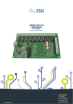
GPIB control. Figure 1 shows the block diagram of such a system.
Figure 1. Typical Block Diagram of Remote GPIB Control with GPIB-232CT-A
An example of such an application is controlling a field test site from an office located in a city. The test site is a
remote station, at which a spectrum analyzer is used to make measurements at a certain time each day. Rather than
having to travel to the remote station each day, modems and the GPIB-232CT-A could be used to interface an
application program, located on a computer in the office, with the spectrum analyzer in the field. The advantage of
using a GPIB-232CT-A is that a second computer is not needed at the field site; and if several test sites were
developed, this could prove to be cost-effective.
Modem Connections
The first step in the development of this application is to establish known modem connections. The user should set
up a local modem connected to the computer with the application program and a remote modem connected to the
GPIB-232CT-A. Although the remote modem must be an external model with auto-answering capability, the local
modem can be either an external or an internal modem. The next step is to establish communication between the
two modems, possibly using a second computer temporarily with the remote modem. If both computers are running
Windows 3.1, a convenient method to communicate between the two computers would be to use Terminal in the
Accessories window. Terminal can write to a computer’s serial port and will prove helpful in configuring the
remote and local modems. However, any application software that has the ability to write to a computer's serial port
can also be used.
_____________________________
Product and company names are trademarks or trade names of their respective companies.
340893A-01
© Copyright 1995 National Instruments Corporation. All rights reserved.
February 1995
Remote Modem Setup
The remote modem needs to be set up to auto-answer after a specified number of rings. To determine how to do
this, consult the technical reference manual for your modem. This application note was developed using the Hayes
2400 modem; therefore, the following settings can be used to configure this type of modem.
For the Hayes 2400 modem, the S-register, S0, must be set to a nonzero value to enable auto-answering. The default
setting for the S0 register is zero, which disables auto-answering. The S0 register must be set to S0=1, S0=2, or
S0=3 for the modem to auto answer after one, two, or three rings, respectively. When the S0 register is changed, the
changes are made to the active profile, which contains the settings that the modem uses during operation. The active
profile is loaded from nonvolatile memory when the unit is powered up. Therefore, when changes are made to the
active profile, it is essential to save those changes to memory. This memory is called stored profiles, and for the
Hayes 2400 modem these profiles are called stored profile 0 and stored profile 1. It is equally important to make
sure that the correct stored profile is loaded when the unit is powered up. This ensures that the remote modem will
power up as an auto-answering modem. The following is an example of the active and stored profiles:
ACTIVE PROFILE:
B1 B16 E1 L1 M1 N1 Q0 T V0 W0 X4 Y0 &C1 &D0 &G0 &J0 &K3 &Q5 &R0 &S0 &T4 &X0 &Y0
S00:002 S01:000 S02:043 S03:013 S04:010 S05:008 S06:002 S07:050 S08:002 S09:006
S10:014 S11:095 S12:050 S18:000 S25:005 S26:001 S36:007 S37:000 S38:020 S44:003
S46:002 S48:007 S49:008 S50:016
STORED PROFILE 0:
B1 B16 E1 L1 M1 N1 Q0 T V1 W0 X4 Y0 &C1 &D0 &G0 &J0 &K3 &Q5 &R0 &S0 &T4 &X0
S00:002 S02:043 S06:002 S07:050 S08:002 S09:006 S10:014 S11:095 S12:050 S18:000
S25:005 S26:001 S36:007 S37:000 S38:020 S44:003 S46:002 S48:007 S49:008 S50:016
STORED PROFILE 1:
B1 B16 E1 L2 M1 N1 P Q0 V1 W0 X4 Y0 &C1 &D0 &G0 &J0 &K3 &Q5 &R0 &S0 &T4 &X0
S00:000 S02:043 S06:002 S07:050 S08:002 S09:006 S10:014 S11:095 S12:050 S18:000
S25:005 S26:001 S36:007 S37:000 S38:020 S44:003 S46:002 S48:007 S49:008 S50:016
With the modem AT commands, the S-registers can be set using the Terminal program in the Accessories program
group found in Windows 3.1, or any other application program that can communicate with a computer’s serial port.
Once these modem settings have been set and saved on the modem, the use of a computer with the remote modem is
no longer necessary. The following is a summary of AT commands used to setup the remote modem:
AT S0=1
AT S0=2
AT S0=3
AT&V
AT&W0
AT&W1
AT&Y0
AT&Y1
* Set modem to auto-answer after 1 ring *
* Set modem to auto-answer after 2 ring *
* Set modem to auto-answer after 3 ring *
* View Configuration Profiles, Active and Stored *
* Store the Active Profile into Stored Profile 0 *
* Store the Active Profile into Stored Profile 1 *
* Select Stored Profile 0 on power-up *
* Select Stored Profile 1 on power-up *
Using the GPIB-232CT-A in S-Mode
To implement a remote GPIB control application, the GPIB-232CT-A can be configured to operate in S-Mode. In
this mode, the GPIB-232CT-A functions as a GPIB system controller, performing the various tasks required in
managing a GPIB network of instruments. These tasks include addressing Talkers and Listeners on the bus,
managing information transfer across the bus and managing requests for service by various devices on the GPIB.
The S-Mode was designed into the GPIB-232CT-A so users could remotely control GPIB instruments using the
computer serial port. Now we are adding modems and telecommunications links to remove the 50 ft. distance limit
of the RS-232 standard.
2
The following table summarizes all of the S-Mode programming functions that can be used to control the
GPIB-232CT-A. Similar to the NI-488.2 software routines and functions, the S-Mode programming set provides
functions for I/O, High-Level Bus Management, Low-Level Bus Management, GPIB Initialization, Serial Polling,
Parallel Polling and Serial Port Management. For a more detailed discussion of each of the functions listed below,
consult the GPIB-232CT-A User Manual.
Table 1. GPIB-232CT-A Functions in S-Mode
cac mode
caddr address
clr address list
cmd count commands
conf option value
echo on/off
eos modes, eoschar
eot on/off
gts mode
id
ist set/clear
lines
ln address list
loc address list
onl/off
pct address
ppc values
ppu address list
rd count, address
rpp
rsc on/off
rsp address list
rsv status byte
sic time
spign on/off
sre on/off
stat modes
tmo values
trg address list
wait mask
wrt count, address list data
xon modes
Become Active Controller
Change the IEEE 488 address of the GPIB-232CT-A
Clear specified device(s)
Send IEEE 488 commands
Read/change configuration
Echo characters received from serial port
Change or disable GPIB end-of-string termination mode
Enable or disable END termination message on GPIB write operations
Go from Active Controller to Standby
Identify system
Set or clear individual status bit for use in GPIB-232CT-A response to
Parallel Polls
Determine state of GPIB control lines
Check for listening devices
Go to Local
Place the GPIB-232CT-A online/offline
Pass Control
Parallel Poll Configure
Parallel Poll Unconfigure
Read data
Conduct (request) a Parallel Poll
Request System Control
Conduct (request) a serial poll
Request service and/or set or change the serial poll status byte
Send interface clear
Ignore serial port errors
Set remote enable
Return GPIB-232CT-A status
Change or disable time limits
Trigger selected device(s)
Wait for selected event(s)
Write data
Change serial port XON/XOFF protocol
The advantage of using S-Mode programming to control the GPIB-232CT-A is that these functions do not require
the presence of the NI-488.2 driver software. The functions are designed to be sent directly to the GPIB-232CT-A
via a serial link, eliminating the additional overhead of the NI-488.2 software.
Establishing Communications with Your Remote GPIB Controller
The following section outlines the steps required to establish a communications link with a remote test site, interface
with the GPIB-232CT-A, and then terminate the communications link with the remote test site once all GPIB
activities have been completed. The following subsections sequentially illustrate each step in the interfacing process
using LabWindows/CVI. A complete listing of the source code appears in Appendix A.
3
Opening Serial Port Communications
The following example code opens access to serial port 2. The serial port is configured to operate at 2400 baud, no
parity, eight data bits, one stop bit and an input/output queue size of 512 bytes. The communication mode is also set
up for Hardware Handshaking (CTS). CheckCOMportError uses the variable ComError to check for serial port
error conditions.
ComError = OpenComConfig (2, "COM2", 2400, 0, 8, 1, 512, 512);
CheckCOMportError(ComError);
ComError = SetCTSMode (2, 1); /* Require Clear To Send signal for handshaking data*/
CheckCOMportError(ComError);
Connecting to the Remote Modem
The following example code illustrates how to configure a local modem via the serial port. Once the configuration
has been sent, the next programming instruction establishes a communications link with the remote site by dialing
the remote modem. Each modem is different so you must determine the correct configuration string for the modem
that you are using.
BytesWritten = ComWrt (2, "ATQ0V1E1S0=0\r\n", 14); /* Send Configuration String*/
Delay (2);
BytesWritten =ComWrt (2, "ATDT97945775\r\n", 14); /* Dial Remote Modem*/
Once the connection has been established, the local modem returns a connection response string in the serial port
input buffer. We use this string to verify that the connection has been made in the desired configuration. The
modem itself is automatically placed into Data Transfer Mode; by writing directly to the serial port, you can send
information over the modem link to your remote GPIB-232CT-A.
while (InQLen < 4) {
InQLen = GetInQLen (2);
}
/* Wait for Response String*/
/*Check input queue for data*/
BytesRead = ComRd (2, databuf, 80);
if (strncmp(databuf, "\r\nCONNECT 2400", 14) == 0)
printf("Connection Succesful!\n");
/*Read Response String*/
/*Check for Valid Connection*/
else { printf("No Carrier: Connect Unsuccessful!\n");
exit (0);
}
Remote Interfacing with the GPIB-232CT-A
The following code illustrates how to initialize the GPIB-232CT-A as System Controller. Users can also use the
tmo, eot, and eos functions to modify time-out, termination method, and the end of string features, respectively. The
code below assumes the default settings of 10 second time-out, EOI termination, and no EOS byte. Each line of
code that executes GPIB operations is followed by the function, CheckGPIBError. It is important to verify that no
GPIB errors have occurred after executing a GPIB operation. See the Application code in Appendix A for a listing
of this function.
BytesWritten = ComWrt (2, "onl 1\r", 6);
CheckGPIBError();
/* Write six byte string to COM2: CT-A Online*/
BytesWritten = ComWrt (2, "sic\r", 4);
CheckGPIBError();
/* Write four byte string to COM2: Send IFC*/
4
The following code illustrates how to query a device on the GPIB for its identification. The “*IDN?” string is used
to prompt a IEEE 488.2 instrument to send its identification string on the next read from that device. The device
resides at address 8.
BytesWritten = ComWrt (2, "wrt 8\n*IDN?\r\n", 13); /*Query device for identification*/
CheckGPIBError();
/*Device resides at address 8*/
BytesWritten = ComWrt (2, "rd #70 8\r\n", 10);
/*Read back identification from device*/
BytesRead = ComRdTerm (2, databuf, 100, 13); /*Read identification from COM2 Buffer*/
CheckGPIBError();
The following code illustrates how to conduct a serial poll by manually polling every device on the bus. In this case
the device at address 8 asserts SRQ when data becomes available. The program returns status information, using the
ReadAllStatus function, when SRQ is detected. All status information is converted from ASCII to Hex and a Mask
is used to check if the SRQI bit of GPIB status has been set. Once SRQI has been detected, the serial poll byte is
read back and available measurement data is retrieved from the instrument. See Appendix A for a listing of the
ReadAllStatus function.
BytesWritten = ComWrt (2, "wait 4096\r", 10);
/*Wait for SRQ*/
while (InQLen < 4) {
/*All Status returned when SRQ occurs*/
InQLen = GetInQLen (2);
/*Check COM2 Input Queue for status*/
}
ReadAllStatus();
/*Read all status information*/
Scan (Status, "%s>%d", &hexStat);
/*Convert ASCII Status to Hex*/
if(hexStat & 0x1000) {
Delay(2);
FlushInQ (2);
FillBytes (spoll, 0, 5, 0);
hexSpoll = 0;
BytesWritten = ComWrt (2, "rsp 8\r", 6);
BytesRead = ComRdTerm (2, spoll, 5, 13);
Scan (spoll, "%s>%d", &hexSpoll);
if (hexSpoll & 0x40) {
BytesWritten = ComWrt (2, "rd #70 8\r\n", 9);
BytesRead = ComRdTerm (2, DCbuf, 70, 13);
}
Delay(2);
FlushInQ (2);
FillBytes (spoll, 0, 5, 0);
hexSpoll = 0;
BytesWritten = ComWrt (2, "rsp 2\r", 6);
BytesRead = ComRdTerm (2, spoll, 5, 13);
Scan (spoll, "%s>%d", &hexSpoll);
if (hexSpoll & 0x40) {
BytesWritten = ComWrt (2, "rd #70 2\r\n", 9);
BytesRead = ComRdTerm (2, DCbuf, 70, 13);
}
}
5
/*Check for SRQ*/
/*Intialize variables*/
/*Read back Serial Poll Byte: Address 8*/
/*Read Serial Poll from COM2 Buffer*/
/*Read data from device*/
/*Read data from COM2 Buffer*/
/*Intialize variables*/
/*Read back Serial Poll Byte: Address 2*/
/*Read Serial Poll from COM2 Buffer*/
/*Read data from device*/
/*Read data from COM2 Buffer*/
Disconnecting from Remote GPIB Controller
Once data collection from the remote GPIB system has been completed, the GPIB Controller should be taken offline.
BytesWritten = ComWrt (2, "onl 0\r", 6);
CheckGPIBError();
/* Place the GPIB-232CT-A off-line*/
Send the escape sequence to place the local modem into Command Mode. Then send the hang up command string.
BytesWritten = ComWrt (2, "+++", 3); /* Place local modem in Command Mode*/
Delay(2);
BytesWritten = ComWrt (2, "ATH\r\n", 5); /* Hang Up*/
To complete your application program, close access to the computer serial port.
ComError = CloseCom (2);
CheckCOMportError(ComError);
General Programming Considerations
Delays are used from time to time to slow down portions of the code in order to allow ample time for information to
be processed through the serial port. You will need to experiment to determine where these delays might be
necessary. In addition, flushing input and output queues prior to sending and receiving data, checking the input
queue prior to reading data from the serial port, and checking for GPIB and serial port errors is highly
recommended.
Error checking is important. However, an even more basic requirement is to clearly understand the syntax involved
in using the S-Mode functions. For example, whenever a command is sent to the GPIB-232CT-A, a specific type of
termination character (Generally a linefeed or a carriage return) must be appended to the end of that command. This
allows the GPIB-232CT-A to terminate correctly and recognize that a command has been sent to it; and so, in
general, be very careful to adhere to the syntax rules outlined for each S-Mode programming function. The
LabWindows/CVI example appearing in Appendix A illustrates the use of these termination characters when using
the S-Mode programming functions to interface with the GPIB-232CT-A.
Many users may choose to use programming languages other than LabWindows/CVI. In general, the entire
interfacing process is streamlined somewhat if the user chooses a language that has standardized functions for easy
access to your serial port. QuickBasic, HP Basic, Visual Basic, and the LabWindows programming environments
have this particular feature. Otherwise, the user must access the UART, that manages the computer serial ports, on a
register level in order to read, write, and check input and output queue lengths for a particular serial port. To assist
in porting the LabWindows/CVI program in Appendix A to another language, Appendix B describes the functions
performed.
6
APPENDIX A
LabWindows/CVI Example Program
/**************************INCLUDES***************************/
#include <formatio.h>
#include <gpib.h>
#include <userint.h>
#include <ansi_c.h>
#include <utility.h>
#include <rs232.h>
/***************************FUNCTION PROTOTYPES******************/
void CheckCOMportError (int);
void ReadAllStatus(void);
void CheckGPIBError(void);
/**************************GLOBALS*******************************/
static int ComError;
static int BytesWritten;
static int BytesRead;
static int Flag;
static int handle;
static int hexStat;
static int hexSpoll;
static int InQLen;
static int
GPIBErrCode;
charStatus[10];
charGPIBerr[5];
charSPerr[5];
charcount[5];
chardatabuf[100];
charDCbuf[100];
charTimeout[5];
charspoll[5];
/*****************************MAIN*****************************/
main(){
/*************OPEN & CONFIGURE COM2: HW HANDSHAKE**********/
ComError = OpenComConfig (2, "COM2", 2400, 0, 8, 1, 512, 512);
CheckCOMportError(ComError);
ComError = SetCTSMode (2, 1);
CheckCOMportError(ComError);
/*************CONNECT TO REMOTE MODEM*******************/
BytesWritten = ComWrt (2, "ATQ0V1E1S0=0\r\n", 14);
Delay (2);
BytesWritten =ComWrt (2, "ATDT97945775\r\n", 14);
Delay(2);
FlushInQ (2);
InQLen = 0;
while (InQLen < 14) {
InQLen = GetInQLen (2);
}
7
BytesRead = ComRd (2, databuf, 80);
if (strncmp(databuf, "\r\nCONNECT 2400", 14) == 0)
printf("Connection Succesful!\n");
else {
printf("No Carrier: Connect Unsuccessful!\n");
exit (0);
}
Delay (2);
FlushInQ (2);
/**********************GPIB-232CT-A INTERFACING*************** **/
/* Command: *IDN? returns instrument ID from 488.2 Instrument.
*/
/* Command: *SRE 16 enables the Service Request Enable register
*/
/*
of a 488.2 instrument. Instrument will assert SRQ
*/
/*
when data ready.
*/
/* Command: VAL1? instructs our device to return DC voltage.
*/
/******************************************************************/
BytesWritten = ComWrt (2, "onl 1\r", 6);
CheckGPIBError();
BytesWritten = ComWrt (2, "sic\r", 4);
CheckGPIBError();
BytesWritten = ComWrt (2, "wrt 8\n*IDN?\r\n", 13);
CheckGPIBError();
BytesWritten = ComWrt (2, "rd #70 8\r\n", 10);
BytesRead = ComRdTerm (2, databuf, 100, 13);
CheckGPIBError();
printf("%s\n", databuf);
BytesWritten = ComWrt (2, "wrt 8\n*SRE 16\r\n", 15);
CheckGPIBError();
BytesWritten = ComWrt (2, "wrt 8\nVAL1?\r\n", 13);
CheckGPIBError();
Delay (2);
FlushInQ (2);
InQLen = 0;
BytesWritten = ComWrt (2, "wait 4096\r", 10);
while (InQLen < 4) {
InQLen = GetInQLen (2);
}
ReadAllStatus();
Scan (Status, "%s>%d", &hexStat);
if(hexStat & 0x1000) {
Delay(2);
FlushInQ (2);
FillBytes (spoll, 0, 5, 0);
hexSpoll = 0;
BytesWritten = ComWrt (2, "rsp 8\r", 6);
BytesRead = ComRdTerm (2, spoll, 5, 13);
Scan (spoll, "%s>%d", &hexSpoll);
if (hexSpoll & 0x40) {
8
BytesWritten = ComWrt (2, "rd #70 8\r\n", 10);
BytesRead = ComRdTerm (2, DCbuf, 70, 13);
}
Delay(2);
FlushInQ (2);
FillBytes (spoll, 0, 5, 0);
hexSpoll = 0;
BytesWritten = ComWrt (2, "rsp 2\r", 6);
BytesRead = ComRdTerm (2, spoll, 5, 13);
Scan (spoll, "%s>%d", &hexSpoll);
if (hexSpoll & 0x40) {
BytesWritten = ComWrt (2, "rd #70 2\r\n", 9);
BytesRead = ComRdTerm (2, DCbuf, 70, 13);
}
}
/********************DISCONNCT FROM REMOTE MODEM**************/
BytesWritten = ComWrt (2, "onl 0\r", 6);
CheckGPIBError();
FlushOutQ (2);
BytesWritten = ComWrt (2, "+++", 3);
Delay(2);
BytesWritten = ComWrt (2, "ATH\r\n", 5);
Delay(3);
/*******************CLOSE COM2**************************/
ComError = CloseCom (2);
CheckCOMportError(ComError);
}/***END MAIN***/
/*******************FUNCTION DECLARATIONS**************************/
/*******************************************************/
/* Function:
CheckCOMportError
*/
/* Parameters:
int error value returned
*/
/* Return Value: NONE
*/
/* Description: This function checks the com port
*/
/* error code and returns the appropriate message.
*/
/* Error codes are referenced in LWCVI user manual.
*/
/*******************************************************/
void CheckCOMportError (int err_value) {
if (err_value < 0) {
MessagePopup ("Communications Error", "Com Port Error: Program Aborted.");
exit (0);
}
}
/******************************************************/
/* Function:
ReadAllStatus
*/
/* Parameters:
NONE
*/
/* Return Value: NONE
*/
/* Description: This function reads all status
*/
/* information returned by "wait".
*/
/******************************************************/
void ReadAllStatus(void) {
9
FillBytes (Status, 0, 10, 0);
FillBytes (GPIBerr, 0, 5, 0);
FillBytes (SPerr, 0, 5, 0);
FillBytes (count, 0, 5, 0);
BytesRead = ComRdTerm (2, Status, 10, 13);
BytesRead = ComRdTerm (2, GPIBerr, 5, 13);
BytesRead = ComRdTerm (2, SPerr, 5, 13);
BytesRead = ComRdTerm (2, count, 5, 13);
}
/******************************************************/
/* Function:
CheckGPIBError
*/
/* Parameters:
NONE
*/
/* Return Value: NONE
*/
/* Description: This function reads all status
*/
/* information returned by "stat". If an error
*/
/* condition exists, display error code and exit prgm.
*/
/******************************************************/
void CheckGPIBError (void) {
Delay (2);
FlushInQ (2);
BytesWritten = ComWrt (2, "stat n\r", 7);
while (InQLen < 4) {
InQLen = GetInQLen (2);
}
ReadAllStatus();
Scan (Status, "%s>%d", &hexStat);
Scan (GPIBerr, "%s>%d", &GPIBErrCode);
if (hexStat < 0) {
printf("GPIB Error: GPIB error code = %d\n", GPIBErrCode);
exit (0);
}
}
10
APPENDIX B
Description of the LabWindows/CVI Functions
Used in Appendix A
Each of the RS-232 functions used in the LabWindows/CVI program in Appendix A is described. This information
outlines the tasks accomplished by each function so that users can translate LabWindows/CVI calls to other
programming languages.
OpenComConfig
This function opens access to a COM port in the desired configuration. Parameters include the COM port number
and its mnemonic, baud rate, parity, data bits, and stop bits, as well as the ability to specify the size of software
buffers that function as input and output queues for transmitting and receiving data. It returns an error code that can
be found in the LabWindows Standard Libraries reference manual.
SetCTSMode
With this function the user can enable Hardware Handshaking. In general, for Hardware Handshaking to work, the
serial devices with which you are interfacing must follow a compatible handshaking protocol and the serial cables
being used must include the lines to support that handshaking protocol. We enable the use of the Clear To Send
(CTS) and the Request To Send (RTS) handshaking lines using SetCTSMode. It returns an error code that can be
found in the LabWindows Standard Libraries reference manual.
ComWrt
This function places a specified number of bytes, contained in a character buffer, into the output queue of a
specified serial port. It returns the actual number of bytes that were placed in the output queue.
ComRd
This function reads a specified number of bytes from the input queue of a specified port and stores the information
in a character buffer. It returns an integer value indicating the number of bytes that were actually read.
FlushInQ/FlushOutQ
Removes all characters from the Input/Output Queue of a specified port.
GetInQLen
This function returns the number of characters in the input queue of the specified port.
CloseCom
Closes a specified COM port and frees the allocated memory buffers for the input and output queues.
11