1
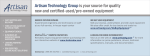
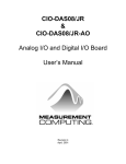
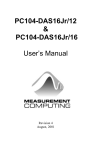
CIO-DAC08-I
and
CIO-DAC16-I
User’s Manual
Revision 3
October, 2000
MEGA-FIFO, the CIO prefix to data acquisition board model numbers, the PCM prefix to data
acquisition board model numbers, PCM-DAS08, PCM-D24C3, PCM-DAC02, PCM-COM422,
PCM-COM485, PCM-DMM, PCM-DAS16D/12, PCM-DAS16S/12, PCM-DAS16D/16,
PCM-DAS16S/16, PCI-DAS6402/16, Universal Library, InstaCal, Harsh Environment
Warranty and Measurement Computing Corporation are registered trademarks of Measurement
Computing Corporation.
IBM, PC, and PC/AT are trademarks of International Business Machines Corp. Windows is a
trademark of Microsoft Corp. All other trademarks are the property of their respective owners.
Information furnished by Measurement Computing Corp. is believed to be accurate and
reliable. However, no responsibility is assumed by Measurement Computing Corporation
neither for its use; nor for any infringements of patents or other rights of third parties, which
may result from its use. No license is granted by implication or otherwise under any patent or
copyrights of Measurement Computing Corporation.
All rights reserved. No part of this publication may be reproduced, stored in a retrieval system,
or transmitted, in any form by any means, electronic, mechanical, by photocopying, recording
or otherwise without the prior written permission of Measurement Computing Corporation.
Notice
Measurement Computing Corporation does not authorize any
Measurement Computing Corporation product for use in life support
systems and/or devices without the written approval of the President of
Measurement Computing Corporation Life support devices/systems are
devices or systems which, a) are intended for surgical implantation into
the body, or b) support or sustain life and whose failure to perform can
be reasonably expected to result in injury. Measurement Computing
Corp. products are not designed with the components required, and are
not subject to the testing required to ensure a level of reliability suitable
for the treatment and diagnosis of people.
(C) Copyright 2000 Measurement Computing Corp.
HM CIO-DAC##-I.lwp
TABLE OF CONTENTS
1 INTRODUCTION . . . . . . . . . . . . . . . . . . . . . . . . . . . . . . . . . . . . . . . . . . . . . . 1
2 SOFTWARE INSTALLATION . . . . . . . . . . . . . . . . . . . . . . . . . . . . . . . . 1
3 HARDWARE INSTALLATION . . . . . . . . . . . . . . . . . . . . . . . . . . . . . . . . 2
3.1 Initial Board Setup . . . . . . . . . . . . . . . . . . . . . . . . . . . . . . . . . . . . . . . . . . 2
3.2 Selecting the Base Address . . . . . . . . . . . . . . . . . . . . . . . . . . . . . . . . . . 2
3.3 Installing the CIO-DAC##-I in the Computer . . . . . . . . . . . . . . . . 3
3.4 Cabling to the CIO-DAC##-I . . . . . . . . . . . . . . . . . . . . . . . . . . . . . . . . 4
3.5 Testing the Installation . . . . . . . . . . . . . . . . . . . . . . . . . . . . . . . . . . . . . . 4
3.6 Signal Connection- Current Loop . . . . . . . . . . . . . . . . . . . . . . . . . . . . 5
3.7 Connector Diagram . . . . . . . . . . . . . . . . . . . . . . . . . . . . . . . . . . . . . . . . . 6
4 REGISTER ARCHITECTURE . . . . . . . . . . . . . . . . . . . . . . . . . . . . . . . . . 7
5 SPECIFICATIONS . . . . . . . . . . . . . . . . . . . . . . . . . . . . . . . . . . . . . . . . . . . . 10
This page is blank.
1 INTRODUCTION
The CIO-DAC-series boards are available in either eight-channel or 16-channel
versions and with either voltage or current (I) outputs. In this manual, the current
output (I) boards are described and are referred to generically as CIO-DAC##-I
unless a specific board is being described.
Analog current outputs are from dual-DAC AD7237s with each output buffered by
2N2222 transistors.
The analog outputs are controlled by writing a digital control and data word as two
bytes (actually a data byte and a data nibble along with a nibble containing channel
information) to two control registers. The control register is double-buffered so a
DAC's output is not updated until both bytes (first low byte, then high byte) are
written.
The CIO-DAC08-I and CIO-DAC16-I have a bank of nine address DIP switches.
(See Figure 2-1.) There are no other switches or jumpers.
2 SOFTWARE INSTALLATION
An installation program labeled InstaCal™ is on the disk shipped with the board.
This program will guide you through board configuration and switch settings. Refer
to the Software Installation Manual for complete instructions regarding installing
and using InstaCal. If you decide not to use InstaCal as a guide, the information
required for configuring the board is provided in the following section.
1
3 HARDWARE INSTALLATION
3.1 Initial Board Setup
The CIO-DAC##-I has only one bank of switches for setting the base address which
must be set before installing the board in your computer. The InstaCal calibration
and test program included with the CIO-DAC##-I will show how these switches are
to be set. Run the program before you open your computer.
The CIO-DAC##-I is setup at the factory as follows:
BASE ADDRESS
300h (768 decimal) Same as data sheet.
3.2 Selecting the Base Address
Unless there is already a board in your system that uses address 300h (768 decimal),
leave the switches as they are set at the factory.
In the following examples, the board (CIO-DAC08-I or CIO-DAC16-I) are set for a
base address of 300h (768 decimal).
NOTE: Use the white numbers on the PCB, not those on the switch.
Certain address are used by the PC, others are free and can be used by the
CIO-DAC##-I and other expansion boards.
9
8
7
6
5
4
3
2
BASE ADDRESS SWITCH Address 300H shown
1
SWITCH HEX
9
200
8
100
7
80
6
40
5
20
4
10
3
8
2
4
1
2
Figure 3-1. Base Addresses- CIO-DAC08-I, CIO-DAC16-I
2
HEX
RANGE
000-00F
020-021
040-043
060-063
060-064
070-071
080-08F
0A0-0A1
0A0-0AF
0C0-0DF
0F0-0FF
1F0-1FF
200-20F
210-21F
238-23B
23C-23F
270-27F
2B0-2BF
Table 3-1. PC I/O Addresses
FUNCTION
HEX
RANGE
8237 DMA #1
2C0-2CF
8259 PIC#1
2D0-2DF
8253 TIMER
2E0-2E7
8255 PPI (XT)
2E8-2EF
8742 CONTROLLER (AT)
2F8-2FF
CMOS RAM & NMI MASK
300-30F
DMA PAGE REGISTERS
310-31F
8259 PIC #2 (AT)
320-32F
NMI MASK (XT)
378-37F
8237 #2 (AT)
380-38F
80287 NUMERIC CO-P (AT)
3A0-3AF
HARD DISK (AT)
3B0-3BB
GAME CONTROL
3BC-3BB
EXPANSION UNIT (XT)
3C0-3CF
BUS MOUSE
3D0-3DF
ALT BUS MOUSE
3E8-3EF
PARALLEL PRINTER
3F0-3F7
EGA
3F8-3FF
FUNCTION
EGA
EGA
GPIB (AT)
SERIAL PORT
SERIAL PORT
PROTOTYPE CARD
PROTOTYPE CARD
HARD DISK (XT)
PARALLEL PRINTER
SDLC
SDLC
MDA
PARALLEL PRINTER
EGA
CGA
SERIAL PORT
FLOPPY DISK
SERIAL PORT
The CIO-DAC##-I BASE ADDRESS switch can be set for address in the range of
000-3FEh so it should not be hard to find a free address area for your board. If not
using IBM prototyping cards or any other board which occupies these addresses,
300-31Fh are free to use. Address not specifically listed, such as 390-39Fh, are free.
3.3 Installing the CIO-DAC##-I in the Computer
1. Turn PC power off.
2. Remove the cover of your computer. Please be careful not to dislodge any of the
cables installed on the boards in your computer as you slide the cover off.
3. Locate an empty expansion slot in your computer.
4. Push the board firmly down into the expansion bus connector. If it is not seated
fully it can fail to work and could short circuit the PC bus power onto a PC bus
signal. This could damage the motherboard in your PC as well as the board.
3
3.4 Cabling to the CIO-DAC##-I
The CIO-DAC##-I connector is accessible through the PC/AT expansion bracket.
The connector is a standard 37-pin D-type male connector. A mating female
connector, such as the C37FF-2, is available from Measurement Computing.
Several cabling and screw termination options are available from Measurement
Computing.
DFCON-37
C37FF-2
C37FFS-5
CIO-MINI37
CIO-TERMINAL
CIO-SPADE 50
D connector, D shell and termination pins to
construct your own cable
2 foot (and longer) ribbon cable with 37 pin D
female connectors
5 foot shielded round cable with molded ends
housing 37-pin female connectors. Also in 10 ft.
37-position, 4 X 4-in. screw terminal board
4 X 16-in. screw terminal board with on-board
prototyping area.
A screw terminal board that accepts spade lugs with
on-board area for prototyping circuitry.
3.5 Testing the Installation
You can test the installation of the CIO-DAC##-I using InstaCal. Select the Test
option to vary the output voltages and monitor them with a Volt Meter.
4
3.6 Signal Connection- Current Loop
The basic CIO-DAC##-I current output circuit is shown in Figure 3-2. Loop power
is from an external power supply. The supply voltage is from 6V to 36V, with 24V
or 36V being typical choices.
4-20mA Control
+
-
LLGND
Figure 3-2. Basic Current Loop
The 4 to 20 mA loop can be configured with either a floating power supply (Figure
3-3) or a floating load (Figure 3-4).
4-20mA Control Board
4-20mA Control
+
Floating
Supply
4-20mA Control Board
4-20mA Control
Load
+
+
+
-
-
-
Supply
Grounded
Load
LLGND
LLGND
Figure 3-3. I-Loop, Floating Supply
Figure 3-4. I-Loop, Floating Load
5
3.7 Connector Diagram
The CIO-DAC##-I connector is a 37-pin D-type connector accessible from the rear
of the PC through the expansion backplate (Figures 3-5, 3-6).
The connector accepts female 37-pin, D-type connectors, such as those on the
C37FF-2, 2-foot cable with connectors.
If frequent changes to signal connections or signal conditioning is required, refer to
the information on the CIO-TERMINAL, CIO-SPADE50 and CIO-MINI37 screw
terminal boards in the Measurement Computing catalog.
-12V 19
GND 18
+12V 17
D/A 15 OUT 16
D/A 14 OUT 15
D/A 13 OUT 14
D/A 12 OUT 13
D/A 11 OUT 12
D/A 10 OUT 11
D/A 9 OUT 10
D/A 8 OUT 9
D/A 7 OUT 8
D/A 6 OUT 7
D/A 5 OUT 6
D/A 4 OUT 5
D/A 3 OUT 4
D/A 2 OUT 3
D/A 1 OUT 2
D/A 0 OUT 1
37
36
35
34
33
32
31
30
29
28
27
26
25
24
23
22
21
20
GND
+5V
LLGND
LLGND
LLGND
LLGND
LLGND
LLGND
LLGND
LLGND
LLGND
LLGND
LLGND
LLGND
LLGND
LLGND
LLGND
LLGND
Figure 3-5. CIO-DAC16-I Connector
Figure 3-6. CIO-DAC08-I Connector
6
4 REGISTER ARCHITECTURE
The CIO-DAC##-I is a simple board to understand. All control and data is
read/written with simple I/O read and write commands. No interrupt or DMA
control software is required. Thus, the board's outputs are easy to control directly
from BASIC, C or PASCAL.
The CIO-DAC##-I has two control and analog output registers.
The first address, or BASE ADDRESS, is determined by the setting of a bank of
switches on the board.
The register descriptions all follow the format:
7
A7
6
A6
5
A5
4
A4
3
A3
2
A2
1
A1
0
A0
the numbers along the top row are the bit positions within the 8-bit byte and the
numbers and symbols in the bottom row are the functions associated with each bit.
To write to or read from a register in decimal or HEX, the following weights apply:
BIT POSITION
0
1
2
3
4
5
6
7
Table 4-1. Register Bit Weights
DECIMAL VALUE
1
2
4
8
16
32
64
128
7
HEX VALUE
1
2
4
8
10
20
40
80
In summary form, the registers and their function are listed in the following table.
Table 4-2. Register Map
ADDRESS
BASE + 0
BASE + 1
WRITE FUNCTION
D/A Least Significant Byte
D/A Most Significant Nibble and
Channel address
READ FUNCTION
None
None
These two registers control all of the DACs on the CIO-DAC##-I. The first register,
BASE + 0, contains the least significant eight bits of D/A code and is written first.
BASE + 0
7
D5
6
D6
5
D7
4
D8
3
D9
2
D10
1
D11
0
D12
(LSB)
The second register contains the most significant four bits of D/A code and the four
bits that determine which channel the data will be sent to. This register is written to
second. A write to this register updates the output of the selected D/A with all 12
bits of the D/A code contained in the two registers.
BASE + 1
7
CH3
6
CH2
5
CH1
4
CH0
3
D1
(MSB)
2
D2
1
D3
0
D4
D12: 1 Data bits
CH3:0 Channel value (0000 = channel 0, 0101 = channel 5, etc.)
Updating the output of a particular DAC channel is a matter of calculating the code
for the output value desired and combining it with the channel number.
To calculate the data code, you first select the output you desire, then apply a
transfer function to that value. The transfer function for code = output is:
FSI / 4095 * CODE = Current Out +4 mA or CODE = Current Out - 4 / 16 * 4095
Full scale current (FSI) is not 20 mA, it is 20 - 4 or 16 mA. Use this in the equation
above.
For Example:
If CODE = 0, current output = 4 mA
If CODE = 4095, current output = 20 mA
8
After calculating the code required for the D/A data, combine it with the code
required for the channel number.
For example, to set the output on channel 3 to 11.890625mA:
CODE = 11.890625mA - 4 / 16 * 4095 = 2020
The digital code for 2020 is 0111 1110 0100.
To this, you would add the value for channel 3 (0011) as the upper nibble for the
second register.
The end result is 0011 0111 1110 0100.
This is written to the registers as:
BASE + 0:
BASE + 1:
228 (or E4 hex)
55 (or 37 hex)
9
5 SPECIFICATIONS
POWER CONSUMPTION
CIO-DAC16-I
+5V supply
+12V supply
−12V supply
CIO-DAC08-I
+5V supply
+12V supply
−12V supply
320 mA typical, 500 mA max
150 mA typical, 190 mA max
100 mA typical, 130 mA max
320 mA typical, 500 mA max
75 mA typical, 100 mA max
50 mA typical, 65 mA max
ANALOG OUTPUT
D/A type
Resolution
Number of channels
CIO-DAC16-I
CIO-DAC08-I
Output Range
Voltage compliance
AD7237
12 bits
16 Current Outputs
8 Current Outputs
4 to 20mA
6 to 36V
D/A pacing
Data transfer
Software paced
Software
Offset error
Gain error
Differential nonlinearity
Integral nonlinearity
Monotonicity
Adjustable to zero
Adjustable to zero
±1 LSB max
±1 LSB max
Guaranteed monotonic to 15 bits over
temperature
±15 ppm/°C max
±5 ppm/°C max
±3 ppm/°C max
System dependant
12 µs typ, 19 µs max
Double buffered output latches
DAC output state on power up and reset
undefined
Gain drift (DAC)
Bipolar offset drift (DAC)
Unipolar offset drift (DAC)
Throughput
Settling time (Full scale step to .01%)
Miscellaneous
ENVIRONMENTAL
Operating temerature range
Storage temerature range
Humidity
0 to 70°C
−40 to 100°C
0 to 90% non-condensing
10
EC Declaration of Conformity
We, Measurement Computing Corp., declare under sole responsibility that the
product:
CIO-DAC16-I
CIO-DAC08-I
Part Number
ISA-Type Current output card
ISA-Type Current output card
Description
to which this declaration relates, meets the essential requirements, is in conformity
with, and CE marking has been applied according to the relevant EC Directives listed
below using the relevant section of the following EC standards and other normative
documents:
EU EMC Directive 89/336/EEC: Essential requirements relating to electromagnetic
compatibility.
EU 55022 Class B: Limits and methods of measurements of radio interference
characteristics of information technology equipment.
EN 50082-1: EC generic immunity requirements.
IEC 801-2: Electrostatic discharge requirements for industrial process measurement
and control equipment.
IEC 801-3: Radiated electromagnetic field requirements for industrial process
measurements and control equipment.
IEC 801-4: Electrically fast transients for industrial process measurement and control
equipment.
Carl Haapaoja, Director of Quality Assurance
Measurement Computing Corporation
16 Commerce Boulevard,
Middleboro, MA 02346
(508) 946-5100
Fax: (508) 946-9500
E-mail: [email protected]
www. measurementcomputing.com