1
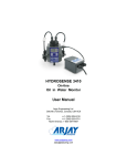
HYDROSENSE 3420 On-line Oil in Water Monitor User Manual Arjay Engineering Ltd. Oakville (Toronto), Canada, L6H 6C9 Tel . ++1 (905) 829-2418 Fax. ++1 (905) 829-4701 North America 1-800-387-9487 www.arjayeng.com [email protected] HydroSense 3420 ppm Oil in Water Monitor ENGINEERING On-line alarm for oil presence in filtered effluent and cooling water The HydroSense 3420 offers a low cost approach to monitoring ppm concentrations of emulsified free oils in clean water. Combining many unique design features into a compact package makes this an ideal solution to monitoring for oil leaks in your water system. • Light scatter technology responds to petroleum, synthetic and vegetable oils • Continuous on-line monitoring without chemicals or lag time • Internal ultrasonic pad helps keep the flow-through sample cell clean to reduce contamination error HYDROSENSE 3420 The HydroSense 3420 uses a light scatter technique to respond to oil contamination in the water. A slip stream approach directs a continuous sample flow through the HydroSense unit and back into the process stream. While it passes through the sample cell a controlled light source is directed into the water. The emulsified oils in the water will scatter the light toward the light sensors placed strategically around the cell. The intensity of light energy is measured to provide an indication of the ppm concentration. Features and Benefits Technical Specifications - Control Unit • ultrasonic disc generates a continuous cleaning action within the sample cell to reduce maintenance frequency • compensation for temperature and lamp deterioration minimizes re-calibration requirements • long life lamp • desiccant chamber keeps electronics dry in humid conditions • continuous display updates every one second • no consumables or chemical used • sample flow returns to the process • sample cell can be exchanged with prepared samples for easy testing and calibration • no tools necessary for routine maintenance Operating Temperature Power Input Alarm Relays Output Standards Enclosure Range Display Resolution Instrument Accuracy Process Accuracy Oil Type 10˚C to 50˚C (optional to 90˚C) 24 vdc or 110 vac or 220 vac 2 x 2 amp, SPDT, dry 4-20 mA or RS-485 UL, CSA, CE Type 4X polycarbonate, IP65 0-100ppm, minimum alarm setpoint 3 ppm 0.1 ppm +/- 0.1 ppm +/- 1.0 ppm under stable conditions All free and non-dissolved oils, > 2 micron Performance The performance is based on the site calibration to a known oil concentration in stable background water. Changes in oil make-up and background stability may affect the output. Through a simple calibration, this unit correlates well with laboratory ISO and EPA methods. The flow-through sample cell is easily removed to insert a test standard. ENGINEERING Arjay Engineering Ltd. http://www.arjayeng.com 2851 Brighton Road Oakville, Ontario telephone: ++1 905-829-2418 Canada L6H 6C9 N. America toll free: 1-800-387-9487 fax: ++1 905-829-4701 Model: HS3420 User Manual TABLE OF CONTENTS SPECIFICATIONS .......................................................................................................................4 1.0 INSTRUMENT OVERVIEW ............................................................................................5 1.1 Description .........................................................................................................5 1.2 Unpacking and Inspection ..................................................................................5 1.3 The Display ........................................................................................................5 1.4 The Touch Pad...................................................................................................6 1.5 Vapor Purge .......................................................................................................6 2.0 SAFETY ..........................................................................................................................7 3.0 INSTALLATION AND COMMISSIONING .......................................................................8 3.1 Mounting & Site Selection ..................................................................................8 3.2 Plumbing ............................................................................................................9 3.2.1 Drain Vent:...........................................................................................9 3.2.2 Wetted Materials:.................................................................................10 3.3 Electrical Connections........................................................................................10 3.3.1 Power: .................................................................................................11 3.3.2 RS-485: ...............................................................................................11 3.3.3 Relays: .................................................................................................11 3.3.4 4-20 mA: ..............................................................................................11 4.0 OPERATION ...................................................................................................................12 4.1 Routine Measurement ........................................................................................12 4.2 Security Access Feature ....................................................................................12 5.0 INSTRUMENT CONFIGURATION .................................................................................13 5.1 Selecting the Output (O/P) .................................................................................13 5.2 Setting the 4-20 mA ...........................................................................................13 5.3 Configuring the RS–485 Port .............................................................................14 5.4 Configuring the Alarms ......................................................................................14 5.4.1 Alarm 1 ................................................................................................15 5.4.2 Alarm 2 ................................................................................................16 5.5 Offset Setting .....................................................................................................16 5.6 Settting the CAL1 and CAL2 ..............................................................................16 5.7 Enabling the Security Access Code ...................................................................16 5.8 Extended Settings ..............................................................................................16 5.9 Speed of Response............................................................................................17 5.10 Displayed Resolution .........................................................................................17 5.11 LCD Backlight Brightness ..................................................................................17 5.12 Setting the Units .................................................................................................18 5.13 Ultrasonic Cleaning ............................................................................................18 5.14 RS-485 Parameters ...........................................................................................18 5.15 Desiccant Alarm .................................................................................................18 5.16 Saving Configuration Settings............................................................................18 5.17 Configuration Settings Sheet .............................................................................19 6.0 INSTRUMENT CALIBRATION .......................................................................................20 6.1 Calibration Metholds ..........................................................................................20 6.2 Calibration Procedures ......................................................................................20 6.3 Calibration Error .................................................................................................21 7.0 ADDITIONAL FEATURES AND OPTIONS ....................................................................22 7.1 Backlit LCD ........................................................................................................22 7.2 Ultrasonic Cleaning ............................................................................................22 7.3 RS-485 Outputs .................................................................................................22 -2- Rev: 2.0 Model: HS3420 8.0 9.0 User Manual TROUBLESHOOTING MAINTENANCE.........................................................................23 8.1 HS3420 Fault Detection .....................................................................................23 8.2 System FAIL Message .......................................................................................23 8.3 Diagnostic Chart.................................................................................................24 8.4 Technical and Customer Assistance..................................................................24 ROUTINE MAINTENANCE .............................................................................................25 9.1 Cleaning the Flow Through Cuvette ..................................................................25 9.2 Replacing or Installing the Desiccant Pouch .....................................................25 9.3 Replacing the Source Lamp...............................................................................25 -3- Rev: 2.0 Model: HS3420 User Manual SPECIFICATIONS Measurement Range 0-100 PPM Accuracy 5% of span Resolution 0.1ppm Response Time Adjustable Display Multi-Line Liquid Crystal Backlit Display Alarms Two Programmable, 120-240VAC 2A Form C Relay Analog Output Powered 4-20mA, 600 drive Communications Port Bi-directional RS-485, Modbus Optional Maximum Water Pressure Integral pressure regulator rated 1380kPa (200 PSI.) Also refer to Flow Rate Flow Rate 100 ml/min. – 1 liter/min. (.026-.26 Gal/min) Operating Temperature 1°C – 50°C (34°F – 122°F) Wetted Materials Nylon, Borosilicate Glass, Silicon, Polypropylene, Stainless Steel Sample Temperature Range 1°C – 50°C (34°F – 122°F) Power Supply 100 – 240 VAC, 47 – 63 Hz, 80VA Insulation Rating Double Insulated, Pollution Degree 2, Overvoltage Category II Environmental Conditions Not recommended for outdoor use. Altitude up to 2000 meters Up to 95 % RH (non-condensing) Enclosure Rating IP 66 /NEMA 4X Certifications CE Approved, ETL listed to UL 3111-1 & ETL Certified to CSA 22.2 No. 1010-1-92 Shipping Weight 2.5 kg (5.5 lbs.) Warranty 1 Year from date of shipment -4- Rev: 2.0 Model: HS3420 User Manual 1.0 INSTRUMENT OVERVIEW 1.1 Description Rev: 2.0 The HS3420 oil in Water monitor from Arjay Engineering Ltd. has been designed for municipal and industrial applications to measure PPM levels of hydrocarbons in aqueous solutions. Typical applications include PPM trace amounts of oil in effluent water from storm water runoff, oil in cooling water, produced water, and oil/water separators. Other measurements and mediums can be monitored on request (i.e. colorants in fluids, etc.). A continuous sample is directed into the cuvette using a pumped or process pressure source. A minimal flow rate is required. The sample is released from the cuvette by a gravity flow to a drain or sump. 1.2 Unpacking and Inspection The table below indicates the items in the shipment. Item Quantity HS3420 c/w Field Terminal Box & Flow Through Assembly 1 User Manual 1 Desiccant Pack 1 Cuvette (Single Pack) 1 Tubing Kit: 1 - shutoff clamp 1 - backpressure valve 2 - connecting tubing with fittings for flow through assembly 1 Remove the instrument from the packing carton. Carefully inspect all items to ensure that no visible damage has occurred during shipment. If the items received do not match the order, please immediately contact the local distributor or the Arjay Engineering Ltd. Customer Service department. Note: The cuvette must be installed prior to operating the instrument. 1.3 The Display Figure 1 illustrates all the items that can appear on the display. The upper row of the display (1) is used for reporting the oil ppm levels and to provide user guidance in the customer setting routine. The lower row of the display (2) is used to communicate error messages and provide user guidance. The display has two icons (3) that are used to indicate the use of access code and offset mode. In addition, mode arrows (4) are used to indicate the current instrument operating mode; AUTO (normal operation), CAL (calibration) and CONFIG (configuration). -5- Model: HS3420 User Manual Rev: 2.0 Figure 1 - Display used in the instrument All items used on the display are shown in this figure 1.4 The Touch Pad Figure 2 illustrates the touch pad. The touch pad has four buttons: MODE/EXIT, , , and . The MODE/EXIT button is used to cycle between the three operational modes of the instrument: CAL, CONFIG, and AUTO (Measurement) mode. The button enters the option (or mode that is highlighted or chosen. The and buttons are used to change settings. Figure 2: The HS3420 Touch Pad. 1.5 Vapor Purge The HS3420 is equipped with a continuous vapor purge system. A replaceable desiccant pouch in the lower portion of the instrument dries the air. System heat is used to warm the air. A fan inside the instrument continuously circulates heated dry air around the optical well and the flow through cuvette. This feature eliminates the need for a dry purge line. The HS3420 monitors the replaceable desiccant pouch condition continuously. The LCD display will show DESC on the lower line in the event that the desiccant pouch needs replacement. Replacement desiccant pouches are available from Arjay Engineering Ltd.. or the local representative . Refer to section 9.2 Replacing or installing the Desiccant Pouch. The desiccant can activate an alarm to notify the operator of a saturated desiccant. See section 5.15 Desiccant Alarm. -6- Model: HS3420 User Manual Rev: 2.0 2.0 SAFETY This manual contains basic instructions that must be followed during the commissioning, operation, care and maintenance of the instrument. The safety protection provided by this equipment may be impaired if it is commissioned and/or used in a manner not described in this manual. Consequently, all responsible personnel must read this manual prior to working with this instrument. In certain instances Notes, or helpful hints, have been highlighted to give further clarification to the instructions. Refer to the Table of Contents to easily find specific topics and to learn about unfamiliar terms. -7- Model: HS3420 3.0 User Manual Rev: 2.0 INSTALLATION AND COMMISSIONING Prior to use for the first time, the supplied desiccant pouch will need to be installed. Refer to section 9.2 Replacing or Installing the Desiccant Pouch. 3.1 Mounting & Site Selection The instrument is designed for wall mounting. If wall mounting is not practical, the instrument can be mounted on any suitable level surface. For ease of service there should be about 20 cm (8”) free area above the instrument; this will ensure enough room for calibration and cuvette maintenance. Choose a location that is easily accessible for operation and service and ensure that the front display rests at eye level. The overall mounting dimensions of the instrument are shown in Figure 3. The recommended mounting screws are M6 (¼”) for the instrument enclosure and M4 (3/16”) for the field terminal box. The HS3420 is designed to have the field terminal box cradled under the sensor portion of the instrument. It is recommended that the field terminal box be mounted first, and then the rest of the instrument be mounted on top. The template on the last page of this manual may be used to establish mounting hole locations. YDRO SENSE 3 400 SERIES ppm OIL IN WATER MONITOR www.arjayeng.com Figure 3: Overall Mounting Dimensions of the Instrument It is critical that the instrument be mounted as close as possible to the sampling point to ensure a quick response time (within 2-3 meters (6-10 ft) of the sampling point). -8- Model: HS3420 3.2 User Manual Rev: 2.0 Plumbing The recommended plumbing for the instrument is shown in Figure 4. The instrument is designed to require very little head pressure to operate; around 6.9kPa (1 PSI). The flow through cuvette is rated for a flow of 100ml/min. – 1 liter/min. (0.026-0.26Gal/min). The integral pressure regulator is rated for a maximum pressure of 1380 kPa (200 PSI.). The maximum allowable fluid temperature is 50°C (122°F). Figure 4: Recommended Plumbing for the Instrument The instrument is equipped to be plumbed using 4.75 mm (3/16”) ID, 8 mm (5/16”) OD flexible tubing. Opaque tubing should be used if the tubing will be exposed to sunlight, to prevent algae growth. In figure 4, there are two flow devices shown. The one on the input side is a shutoff clamp used during cuvette maintenance. The other device is a backpressure valve. Backpressure may be required to prevent air from coming out of solution, which may be observed as tiny air bubbles. 3.2.1 Drain Vent: The HS3420 has been fitted with a drain vent in the “OUT” bulkhead fitting. This fitting allows for atmospheric equalization, thus helping to alleviate bubble formation in the cuvette. Refer to Figure 4. Upon initial flow minor leakage may occur through the drain vent. This will subside once normal flow is established. For some high pressure systems, where the vent hole continuously leaks, a 6:32 seal screw is provided which should be inserted into the vent hole and tightened. -9- Model: HS3420 3.2.2 User Manual Rev: 2.0 Wetted Materials: Arjay Engineering Ltd. Accepts no responsibility for damage caused by the introduction of vapors, fluids or other materials into the instrument process stream shich is not compatible with the instrument’s wetted materials. A list of the wetted materials ca be found in the specifications on page 4 of this manual. 3.3 Electrical Connections All of the electrical connections to the instrument are made through the field terminal box, which should be located directly under the sensor portion of the instrument. The connections are labeled within the terminal box and are self-descriptive (see Figure 5). Please follow all local and government recommendations and methods for installation of electrical connections to and between the instrument and other peripheral devices. Plugs are inserted into the alarm and 4-20mA/RS-485 cable bulkheads when shipped, to ensure a watertight seal. These plugs should be removed and discarded when cabling to either of these connections. The power cable bulkhead will accept cable diameters from 5.8mm (.230 in.) up to 10 mm (.395 in.). All terminals are designed to accept wires in the range of 14-28 AWG. All wires should be stripped to a length of 6 mm (¼”). A strain relief strap is provided to reduce tension on the power terminals. It is the user’s responsibility to assure that the watertight seal is maintained after the terminal box has been wired for operation. If any of the bulkheads are not tightened properly around a cable or plug, the ratings of the instrument will be jeopardized and there is a possibility of creating a shock hazard. Note: Only qualified electricians should be allowed to perform the installation of the instrument as it involves a line voltage that could endanger life. Figure 5: Electrical Connections for the Instrument - 10 - Model: HS3420 3.3.1 User Manual Rev: 2.0 Power: The instrument is equipped with a 100-240 VAC, 47-63 Hz switching power supply; please verify that the line voltage falls within these specifications. It is recommended that a circuit breaker be placed prior to the power connection to allow for service. While making connections, refer to Figure 5. The HS3420 is not supplied with a power cord. 3.3.2 RS-485: The RS-485 half-duplex (2-wire) digital interface operates with differential levels that are not susceptible to electrical interferences. This is why cable lengths up to 3000 ft can be implemented. The last device on each bus may require terminating with a 120-ohm resistor to eliminate signal reflection on the line. Do not run RS-485 cables in the same conduit as power. To prevent damage to the instrument, ensure that power is disconnected prior to making connections. For ease of connecting, remove the plug in terminal block. Connections are labeled beneath this termination. 3.3.3 Relays: The Alarm 1 and Alarm 2 relays are mechanical relays rated at 240 VAC 2A. Please note that the relays are labeled NO (Normally Open), NC (Normally Closed) and C (Common). As these alarms are configured fail-safe, the normal condition is with power applied to the HS3420 and in a non-alarm condition. Operation of these alarms is covered in section 5.4 Configuring the Alarms. 3.3.4 4-20 mA: The 4-20 mA output is driven by a 15 VDC power source and can drive recorder loads up to 600 ohms. This 4-20 mA output is isolated from line power and earth ground. Do not run 4-20 mA cables in the same conduit as power. Operation of this output is covered in section 5.2 Setting the 4-20 mA. Optional optically isolated outputs are available as a factory installed option. Note: The installation of the 4-20 mA isolator will render the RS-485 non-operational. Ensure each instrument is not powered when connecting the 4-20 mA. To prevent damage to the instrument, ensure that power is disconnected prior to making connections. For ease of connecting, remove the plug in terminal block. Polarities of the connections are labeled beneath this termination. - 11 - Model: HS3420 4.0 User Manual Rev: 2.0 OPERATION The HS3420 allows for the measurement of the oil concentration of process water on-line. The oil concentration of the process water is reported in ppm, but may be reported in mg/L. Readings above 100 ppm are outside the range of this instrument. Readings above 100 ppm will cause the display to flash indicating an over range condition. During normal operation, the instrument will have the arrow beside AUTO highlighted with the current scale displayed on the lower row of the display and the measured reading on the upper row of the display (see illustration below). AUTO CAL CONFIG 4.1 3.4 PPM Routine Measurement The following steps describe how to measure the oil concentration of a sample using this instrument: Apply power to the instrument and allow the unit to warm up (typically 45 minutes – 1 hour on initial commissioning). When a continuous process stream is flowing through the instrument, the instrument will display the measured oil concentration of the sample by displaying it on the LCD screen. In addition, the equivalent signal is provided on the analog (4-20 mA) output, or the digital output, depending on the options selected. 4.2 Security Access Feature The instrument is equipped with a security access code feature that can be activated in the configuration mode. If the security feature is enabled (factory set for OFF), the screen shown in the illustration below will appear when the MODE/EXIT button is pressed. AUTO CAL CONFIG 000 CODE The security code (333) must be entered to gain access to CAL or CONFIG menus. Notice that the first number in the code is flashing; the flashing indicates that this is the number to be changed. Use the or arrows to select the first of the three numbers in the code and then press the button to accept the first number of the code. Now enter the second number in the code. Proceed as with the first number followed by . Then repeat the process for the third number in the access code, and finish with the button. If the valid access code has been selected, the instrument will be directed to the calibration mode. If the wrong access code is selected, the instrument will return to the AUTO mode. Refer to section 5.7 Enabling the Security Access for more information. - 12 - Model: HS3420 5.0 User Manual Rev: 2.0 INSTRUMENT CONFIGURATION The instrument has been designed to provide the ability to customize the instrument according to needs at any time during normal operation. This mode has been split into sub-menus to facilitate instrument configuration. This section describes how to use each of the sub-menus to configure the instrument. While in the configuration mode, the instrument has a time-out feature that automatically returns the system operation to the AUTO mode after a fifteen (15) minute period. Enter the CONFIG mode of the instrument by pressing the MODE/EXIT button until the arrow beside CONFIG is illuminated. Note: To exit the CONFIG mode, press the MODE/EXIT button. 5.1 Selecting the Output (O/P) The first configuration selection is the O/P. The selections are 4-20 for the 4-20 mA output, 485 for the RS-485 and OFF if no outputs are required. Select the desired output by using the and buttons. Once the desired output has been set, press the button to accept it. The next prompts will depend on the output selected. 5.2 Setting the 4-20 mA AUTO CAL CONFIG 4 - 20 O/P If the 4-20 mA output was turned on, prompts to set the lower (LOLM) and upper (UPLM) ppm limits corresponding to the 4 mA and 20 mA output levels will be displayed. The first prompt will be the ppm limit assigned to the 4 mA output level: Select the ppm to assign to the LOLM using the and buttons. AUTO CAL CONFIG 0.0 LOLM Once the desired ppm level has been set, press the button to accept it. The next, prompt will be the ppm level assigned to the 20 mA output level (UPLM on the lower row of the LCD display). Select the ppm level to assign to the UPLM using the and buttons. Once the desired level has been set, press the button to accept it. AUTO CAL CONFIG - 13 - 100 UPLM Model: HS3420 5.3 User Manual Rev: 2.0 Configuring the RS–485 Port If the instrument is equipped with this option, and the I/O selection is changed to 485, prompts will appear for setting the baud rate and the address. Select the correct baud rate (1200, 2400, 4800, 9600, or 19200) for operation of the I/O port by pressing the or buttons to change the displayed baud rate. AUTO CAL CONFIG 9600 BAUD Press the button to continue on and select the desired instrument address using the or buttons. Once the selection is satisfactory, press the button. 1 AUTO CAL CONFIG ADDR To enable the Modbus mode, select ASCII or RTU. Refer to the Modbus Manual, if this option was purchased, for more information. 5.4 Configuring the Alarms Two relays are provided that are designed to operate as two independent programmable alarms. Three types of information must be input to fully program each alarm: 1. The alarm function (HI, LO, or OFF) 2. The alarm set point (level at which the alarm activates) 3. The delay time for the alarm: the time (set in seconds) that the set point must be exceeded prior to alarm activation and the time before resetting the alarm (prevents chattering in the relay) These three items are described below: Alarm Function: The alarms can either be turned OFF or programmed to operate in one of two different manners: 1. HI alarm: the relay changes state when the measured ppm level is higher than the programmed alarm level for a prescribed amount of time. 2. LO alarm: the relay changes state when the measured ppm level is lower than the programmed alarm level for a prescribed amount of time. Note: The relays automatically change state when an internal system failure is detected. Alarm Set Point: The level at which an alarm activates is called the alarm set point. On the instrument, the alarm set point is designated as “S/P”. The set point is adjustable to any valid ppm level over the range of the instrument in steps of 0.01 ppm. Alarm Delay Time: The alarm delay times are used to prevent chattering of the alarm when the measured ppm level is close to the set point. The function of the delay times is as follows: - 14 - Model: HS3420 User Manual Rev: 2.0 Delay On: The ppm level must exceed the alarm set point continuously for at least this number of seconds before the alarm activates. If the delay on time is set at 5 seconds and the process ppm level exceeds the set point continuously for only 4 seconds, the alarm will not be activated. However, process ppm level exceeds the set point continuously for 5 seconds or more, the instrument will activate the alarm. Delay Off: The ppm level must not exceed the alarm set point continuously for at least this number of seconds prior to deactivation of the alarm. If the delay off time is set to 5 seconds and the process has exited out of the alarm condition, the alarm will be reset only if the process is out of the alarm condition for a continuous 5 seconds. Otherwise, the instrument will still signal an alarm condition. 5.4.1 Alarm 1 Alarm 1 Function: The ALM1 is displayed and the display indicates the current function of alarm 1 (HI, LO, or OFF). Use the or buttons to cycle through and select the desired function. Press the button to accept the selection. If the alarm was turned OFF a prompt will appear to set up alarm 2 (go to section 5.4.2). If, on the other hand, one of the other functionalities was selected a prompt will appear to set the delay times. Alarm 1 Set Point: This prompt is used to select the set point for this alarm; this is indicated by “S/P” shown on the lower row of the display. Select the desired alarm level by using the and buttons. Once the desired set point has been set, press the button to accept it. Alarm 1 Delay Times: Delay On: The following display will appear to allow to select the number of seconds currently set for the “delay on” time. 5 AUTO CAL CONFIG DLY The current selected number of seconds will be shown. Select the desired number of seconds for the “delay on” time for this alarm using the and buttons. Once the desired delay time has been set, press the button to accept it. Delay Off: Next, the following display will appear to select the number of seconds currently set for the “delay off” time. 5 AUTO CAL CONFIG DLY The current selected number of seconds will be shown. Select the desired delay off time for this alarm using the and buttons. Once the desired delay time has been set, press the button to accept it. After the settings for alarm 1 have been completed, prompts will allow for the set up of the information on alarm #2. - 15 - Model: HS3420 5.4.2 User Manual Rev: 2.0 Alarm 2 Repeat the procedure listed in section 5.4.1 to set up the parameters for alarm 2. If a selection was made to turn the alarm OFF, the next selection for the speed of response RESP is shown. If one of the other functionalities is selected, a prompt to set the delay times and the set point, as with Alarm #1, will be displayed. 5.5 Offset Setting OFST (Offset) is used only for factory setting. 5.6 Settting the CAL1 and CAL2 The ppm values for the two calibration points (CAL1 and CAL2) must be determined before calibration. See section 6.2 to determine your ppm values. These are entered as the following: Push the .button until CAL1 is displayed on the lower row. On the top row of the display will indicate the ppm value of sample or standard. Change this value by using or buttons. Once the desired ppm value has been set, press the button to accept it. The next, CAL2 is displayed on the lower row. On the top row of the display will indicate the ppm value of sample or standard. Change this value by using or buttons. Once the desired ppm value (normally, 0ppm) has been set, press the button to accept it. AUTO CAL CONFIG 5.7 30.0 CAL1 AUTO CAL CONFIG 0.0 CAL2 Enabling the Security Access Code The instrument is equipped with a security access. If this option is turned on, the user is required to input the access code into the instrument to get to any mode other than AUTO. The only code is 333. This code may not be changed. See section 4.2 for more information on this security feature. The security key icon will be visible and flashing on the display whenever the access option is selected using the or buttons. (On or OFF). AUTO CAL CONFIG 5.8 On CODE Extended Settings The last few settings are grouped together to prevent them from being adjusted by accident. If extended settings is set to OFF, pressing the button will save all settings and the HS3420 will automatically return to the normal AUTO mode of the instrument. To gain access to the extended settings, select On using the or buttons and press the button. - 16 - Model: HS3420 User Manual AUTO CAL CONFIG 5.9 Rev: 2.0 On EXTD Speed of Response The speed of response for both displayed and output values of ppm can be adjusted in this menu. The default setting is 10, however 100 response speeds are available. Although the displayed number is a relative speed, the approximate response time, in seconds, is the displayed number multiplied by 5. Select the desired speed of response using the and buttons. Press the button to accept it. To avoid reading air and other anomalies, select the slowest speed (highest number). Select the fastest response where monitoring of rapid changes is needed. AUTO CAL CONFIG 5.10 10 RESP Displayed Resolution The instrument is equipped with the ability to display several levels of resolution. The instrument can display up to four digits to the right of the decimal place for oil concentration readings below 10 ppm. The default setting is 0.1 ppm. If the last digit or two is not stable, adjust the resolution to hide these digits. 0.1 AUTO CAL CONFIG RES Change the resolution by pressing the or button. When the desired digit resolution has been selected, press the button. 5.11 LCD Backlight Brightness The LCD backlight brightness may need to be adjusted. This is of particular interest if multiple instruments are located in the same area and it is desired for the entire group to have the same appearance. Ten levels are available. The default brightness is 8. 7 AUTO CAL CONFIG BRT Change the brightness by pressing the or button. When the desired brightness has been selected, press the button. - 17 - Model: HS3420 5.12 User Manual Rev: 2.0 Setting the Units The most common unit is ppm, however the instrument can display in mg/L.. All instruments are shipped from the factory set in ppm mode. Make a selection using the and buttons then press the button. AUTO CAL CONFIG 5.13 PPn UNIT AUTO CAL CONFIG NGL MGL Ultrasonic Cleaning This allows for a selection menu to turn off the ultrasonic cleaning function if desired. The default mode is On. Make a selection using the and buttons then press the button. On AUTO CAL CONFIG 5.14 CLN RS-485 Parameters For instruments manufactured on or after June 2003, the following menus can be used to modify the RS-485 parameters. These menus will only appear if the RS-485 is enabled (see 5.1). The default is 8 Bit, no (nOnE) Parity, 1 Stop Bit. Make selections using the and buttons then press the button to move to the next menu. 8 AUTO CAL CONFIG 5.15 BITS AUTO CAL CONFIG nOnE PRTY 1 AUTO CAL CONFIG STOP Desiccant Alarm When the humidity detector in the HS3420 indicates that the internal environment is close to the point where humidity could cause condensation, the instrument will display DESC as a warning. If desired, a desiccant warning can activate the alarms and send the 4-20mA to 2mA. To activate the alarms when the desiccant fails, select On in the DESC menu. The default for this menu is OFF. Make selections using the and buttons then press the button to move to return to AUTO mode. AUTO CAL CONFIG 5.16 OFF DESC Saving Configuration Settings If extended settings is set to OFF, pressing the button will save all settings and the HS3420 will automatically return to the normal AUTO mode of the instrument. - 18 - Model: HS3420 User Manual Rev: 2.0 If extended settings is set to On, after the last menu of the extended settings, pressing the button will save all settings and the HS3420 will automatically return to the normal AUTO mode of the instrument. The CONFIG menu may be used at any time to reset or change any of the parameters. The CONFIG menu may be exited at any point in the menu by using the MODE/EXIT key. Any features that have been modified will be saved. 5.17 Configuration Settings Sheet PARAMETER DESCRIPTION FACTOR Y SETTING Output selection 4-20mA LOLM The lower ppm limit corresponding to 4 mA 0.0ppm UPLM The higher ppm limit corresponding to 20 mA 100.0pp m ALM1 The current function of alarm 1 O/P HI The set point of Alarm 1 30 PPM DLY The number of seconds for the "delay on" time for the alarm 1 5 seconds DLY The number of seconds for the "delay off" time for the alarm 1 5 seconds ALM2 The current function of alarm 2 S/P HI The set point of Alarm 2 50 PPM DLY The number of seconds for the "delay on" time for the alarm 2 5 seconds DLY The number of seconds for the "delay off" time for the alarm 2 5 seconds OFST The operational status of the offset function CAL1 The ppm value of the first calibration point CAL2 The ppm value of the second calibration point CODE The access code into the instrument OFF EXTD The last few settings (see the following) are grouped together OFF RESP The speed of response for both displayed and output values 10 RES The decimal place for the ppm readings 0.1 BRT The LCD backlight brightness UNIT The instrument display unit CLN The ultrasonic cleaning function ON The Desiccant alarm function OFF S/P DESC - 19 - OFF 30 PPM 0 ppm 8 ppm USER SETTING Model: HS3420 6.0 User Manual Rev: 2.0 INSTRUMENT CALIBRATION The instrument was calibrated and tested prior to leaving the factory using 30ppm turbine oil. Therefore, it is possible to use the instrument directly out of the box. Under normal conditions, re-calibration is recommended at least once every three months. Relay contacts are held at the last valid condition and will not change state while the instrument is in the calibration and/or in the configuration mode. While in the calibration mode, the instrument has a time-out feature that automatically returns the system operation to the AUTO mode after a fifteen (15) minute period of inactivity. 6.1 Calibration Metholds There are 3 methods available to calibrate the HS3420. Each method requires two calibration inputs: a zero calibration using 0ppm clean water and a span calibration using a known ppm concentration. The HS3420 is for an alarm and trending monitor only. Therefore, absolute calibration accuracy is not required. Method 3 is widely used and an acceptable method for calibration. Method 1: Make a sample of a known concentration using the oil type and mixing it with water. Blending samples that are representative of sample conditions is difficult to do. Using Acetone in equal parts to the oil will aide in blending the sample. Method 2: Have an oil contaminated process sample analyzed by a local lab to determine the ppm value. Use a quantity of the same sample for calibration. An NTU sample can be tested after calibration to assign a PPM value for future calibration using Method 3. Method 3: Use a NTU Formazin sample that closely relates to the oil response factor. Typical Response Factors Oil Type 10NTU Diesel / Turbine Oil 30 ppm customer oil name ppm Note Customer oil name and ppm value of 10 NTU from Method 2 NTU Formazin samples are available from Arjay Engineering Ltd or laboratory supply outlets. Arjay calibration Standards are stable and have a 12 month shelf life. 6.2 Calibration Procedures Before the calibration, the ppm values of the samples or standards should be known. 1. See section 5.6 and 5.16 if the ppm values of CAL1 (first point of calibration) and CAL2 (second point of calibration) need to be changed. These are factory set at 30 ppm and 0 ppm. 2. Select the calibration function of the instrument by pressing the MODE/EXIT button once. The arrow beside CAL will be illuminated on the display. The lower display shows the ppm value set during configuration (CAL1), see section 5.6. - 20 - Model: HS3420 User Manual AUTO CAL CONFIG 30.0 30 AUTO CAL Rev: 2.0 30.0 CONFIG 3. Remove the flow through unit. 4. Insert the requested standard or known ppm sample that represents the ppm value on the lower display. 5. Press the button to accept the first point calibration. 6. The upper display will count down 30 seconds and then display the ppm value. 7. The lower display will now change to the second point calibration. 8. Insert the requested 0ppm clean water of standard. 0.0 AUTO CAL CONFIG 0 AUTO CAL 0.0 CONFIG 9. Press the button to accept the second point calibration. 10. The upper display will count down 30 seconds. 11. The instrument will return to AUTO mode at the end the calibration. 12. Calibration is now completed. 13. Reinsert the flow through unit. Note: During calibration, the fan inside the instrument is turned off to extend the life of the desiccant. The fan will be turned on during calibration countdowns and after returning to the AUTO mode or after five minutes, which ever comes first. It is recommended that the measurement chamber be kept covered during the calibration period and that the flow through cuvette be replaced immediately after the calibration to prevent premature saturation of the desiccant. 6.3 Calibration Error If the screen shown below, is displayed after calibration, the internal diagnostics have determined that the calibration standards were either bad or that they were inserted in the wrong order. Either check the standards and recalibrate AUTO CAL CONFIG Err CAL To recalibrate press the MODE key and start the calibration sequence again. - 21 - Model: HS3420 User Manual 7.0 ADDITIONAL FEATURES AND OPTIONS 7.1 Backlit LCD Rev: 2.0 The backlit LCD allows for easier readability of the LCD display in low light or no light conditions. The backlight is intended for continuous operation. The brightness is adjustable from a menu in the CONFIG mode. 7.2 Ultrasonic Cleaning This option is used to continuously clean the flow through cuvette. It is not intended to clean cuvettes that are already dirty, or replace manual cleaning entirely. The system will increase the time between cleanings dramatically. Please note that the system requires the use of a special cuvette. This cuvette must be used for the system to operate correctly. The system works by sending an ultrasonic frequency through spring connections into a piezo transducer bonded to the bottom of a flow through cuvette. The system can detect that an incorrect cuvette is installed, an error has occurred in the transducer or the transducer is not making contact with the spring connections. This error is indicated by CLN being posted to the lower screen. Since this is an error condition, the alarms will be set and the 4-20 mA will be sent to 2 mA. If the correct cuvette is installed, and the error is still posted, try rotating the flow through unit slightly to improve the connection. If this fails to work, the cuvette may have to be replaced. The detection for this cuvette only operates in AUTO mode. If the system is operating correctly AUTO will flash. Note: The cuvette must be completely dry before it is inserted into the sensor. If there is any visible moisture present on the cuvette or transducer, there is a great risk of damaging the sensor electronics and the transducer. Be sure to clean and dry the cuvette completely just before inserting it into the sensor. After installing a cuvette, there will be a 30 minute period where the lower screen will post DRY to the lower screen. During this time, the ultrasonic circuit will not operate to allow the Vapor Purge system to remove all moisture from the ultrasonic transducer. The Vapor Purge system can NOT remove large droplets of water, only residual moisture. The DRY message is normal and is not considered an alarm condition; therefore no alarms will be implemented. If the cuvette is removed during this period no CLN alarm is posted until the 30 minute DRY period times out. Note: for the Vapor Purge system to function properly, all instrument seals must be maintained and the desiccant pack must be in good condition (no DESC display). 7.3 RS-485 Outputs Modbus protocol communication is optionally available on all models. The Modbus information is covered in a separate manual included with this option. - 22 - Model: HS3420 User Manual 8.0 TROUBLESHOOTING MAINTENANCE 8.1 HS3420 Fault Detection Rev: 2.0 The HS3420 performs continuous diagnostic monitoring. In the HS3420 there are three levels of fault detection; warnings, errors and failures. Any faults are displayed in a queue form in the bottom row of the LCD. A warning is simply a screen indication of a problem. No alarms are activated. If the desiccant alarm is turned off and the desiccant becomes saturated, a screen warning of DESC will appear. An error indicates a failure or a problem that usually can be corrected by the operator. These errors consist of lamp out (LAMP), 4-20 mA loop open (MA), bad calibration (CAL), if desiccant alarm activated and replacement required (DESC), if enabled no flow (FLOW) (if equipped with the flow switch). If the HS3420 is equipped with ultrasonic cleaning, an additional message will indicate that the ultrasonic transducer is not making contact or the flow through has been removed (CLN). If any of these conditions occurs, both alarm relays will be activated and the 420 mA output will be held at 2 mA. If any of these errors occur the instrument will still display readings, however the accuracy is not known and the instruments readings should not be trusted. A failure is a system fault. This is NOT a problem that the operator can correct, and the unit must be returned to the factory for service. These failures consist of failures in the CPU, A/D, EEPROM or other devices internal to the instrument (FAIL). If a failure occurs, the instrument will not function properly and will display the word FAIL on the lower row, both alarm relays will be activated and the 4-20 mA output will be held at 2 mA (if 4-20 mA is selected). If any fault conditions occur, the message indicating the fault will be shown on the lower row of the display. 8.2 System FAIL Message Normally, this condition indicates that the instrument will require servicing. Contact Technical Service of Arjay Engineering Ltd. Arjay Engineering Ltd. 2851 Brighton Road Oakville, Ontario, Canada, L6H 6C9 Phone: (905) 829-2418 Fax: (905) 829-4701 North America 1-800-387-9487 Email: [email protected] www.arjayeng.com - 23 - Model: HS3420 8.3 User Manual Rev: 2.0 Diagnostic Chart Symptom Cause Cure Lower display shows MA 4-20 mA loop open Check wiring. See sections 3.3.4 and 7.2 Lower display shows DESC Desiccant pouch bad Change desiccant pouch. See section 9.2 Lower display shows LAMP Lamp failed Replace lamp. Refer to section 9.3 Lower display shows FLOW Sample flow has stopped Restore flow. Contact Arjay about factory installed option Lower display shows FAIL Major system fault Refer to section 9.1 & 9.2 Readings are higher than expected (1) Bubbles in solution (1) Ensure that the drain vent is open and is not obstructed. See section 3.2.2. (2) Apply backpressure. See section 3.2 and figure 4 (3) For sever cases of bubbles a stilling chamber is available. Call Arjay Engineering Ltd. (2) Condensate or leaky cuvette Check flow through cuvette for condensate or leaks. (3) Flow through cuvette dirty Clean cuvette. See section 9.1 Instrument out of calibration Recalibrate. Refer to section 5 Readings are erratic (1) Bubbles in solution (2) Debris in flow through (1) See above (2) Clean debris from cuvette Readings are lower than expected Instrument out of calibration Recalibrate. Refer to section 5 Upper display flashes Sample Over-Range Check sample. Sample may be too high to read. 8.4 Technical and Customer Assistance If for any reason assistance is needed regarding this instrument please do not hesitate to contact Technical Service of Arjay Engineering Ltd: Arjay Engineering Ltd. 2851 Brighton Road Oakville, Ontario, Canada, L6H 6C9 Phone: (905) 829-2418 Fax: (905) 829-4701 North America 1-800-387-4701 Email: [email protected] www.arjayeng.com - 24 - Model: HS3420 User Manual 9.0 9.1 Rev: 2.0 ROUTINE MAINTENANCE Cleaning the Flow Through Cuvette Measurement cuvettes used for both grab sample and the flow through should be clean and free of marks or scratches. Cleaning is accomplished by cleaning the interior and exterior with a detergent solution and then rinsing several times with distilled or de-ionized water. The cuvette can be replaced by first shutting off the flow using the provided shutoff clamp; unscrewing the old cuvette and replacing with a fresh clean one. 9.2 Replacing or Installing the Desiccant Pouch The HS3420 continuously checks the condition of the desiccant. When the desiccant gets in such a condition that it may cause problems, the instrument will display DESC on the lower portion of the display to indicate the presence of humidity. See 5.15 Desiccant Alarm. Proper use of the supplied desiccant is essential in maintaining the performance of the instrument. The desiccant has been designed to have a long life; however, replacement of the desiccant pouch will be required from time to time. HUMIDITY INDICATOR (HUMONITOR R ) CARD It is essential that the enclosure seal on the instrument base be maintained to ensure adequate desiccant life. Inspect the seal each time the desiccant pouch is replaced. Replace or reseat the seal if it is found to be defective. The desiccant should be replaced when the instrument displays DESC. A new sealed desiccant pouch and indicator card are available from Arjay Engineering Ltd. To initially install or remove the old desiccant, simply unscrew the four corner thumbscrews and remove the electronics half of the instrument. Open the bag protecting the new desiccant pouch and replace (or install for a new instrument) in the desiccant tray assembly. To speed up the recognition, by the instrument, of the new desiccant it will be necessary to reset the instrument by disconnecting the sensor interconnect cable for 2 seconds and then reconnecting it. REPLACEABLE DESICCANT POUCH (PART#: A00582) SENSOR BOTTOM Note: Once the bag is opened, install the desiccant pouch immediately to prevent premature degradation of the desiccant. 9.3 Replacing the Source Lamp The source lamps in the HS3420’s are designed for long life. The white light version is rated for 7 years. If the lamp should need replacement, we recommend calling Arjay Engineering Ltd for assistance. - 25 - MOUNTING TEMPLATE ALL DIMENSIONS ARE IN INCHES (MILLIMETERS) NOTE: 1) SEE THE MOUNTING INSTRUCTIONS IN THE MANUAL FOR MOUNTING HARDWARE SIZES. 2) PROVIDE AT LEAST 8 INCHES (200 MM) OF FREE SPACE ABOVE THE SENSOR FOR EASY REMOVAL OF THE FLOW HEAD AND INSERTION OF THE CALIBRATION STANDARDS.