1
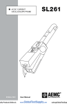
OPERATION Please make sure that you have already read and fully understand the WARNING section on page 1. Making Measurements with the AC Current Probe Model MN379 Connect the black lead of the current probe to “common” and the red lead to the AC voltage input on your DMM or other voltage-measuring instrument. The AC current probe has an output of 200mV/A and 10mV/A. This means that with the probe in the 10mV/A position, for 100A AC in a conductor around which the probe is clamped, 1V AC will come out of the probe leads to your DMM or instrument. Select the range which corresponds to the measured current. If the current magnitude is unknown, start with the probe in the 10mV/A position and if the current is < 5 amps the probe can be switched to the 200mV/A position for the higher resolution. Clamp the probe around the conductor. With the probe in the 10mV/A position take the reading on the meter and multiply it by 100 to obtain the measured current (e.g, 160mV reading = 160 x 100 = 16,000mA or 16A). The 5A range is design to measure on 5A current transformer. The output is 1V rms for 5A measured. Enter a scale factor in the meter if possible for direct reading. For best accuracy, avoid if possible, the proximity of other conductors which may create noise. Tips for Making Precise Measurements AC Current Probe Model MN379 User Manual DESCRIPTION The MN379 (Catalog #2153.01) is the latest in compact AC current probes. Designed to meet the most stringent demands in industry and electrical contracting, it also meets the latest safety and performance standards. The probe has a measurement range up to 120Arms, a range and resolution capable of displaying 10mV of output per amp of measured current, a voltmeter accuracy of 0.5% or better to take full advantage of the accuracy of the probe and an input impedance of 1M. WARNING The safety warnings are provided to ensure the safety of personnel and proper operation of the instrument. Read the instruction completely. When using a current probe with a meter, it is important to select the range that provides the best resolution. Failure to do this may result in measurement errors. • Use caution on any circuit: potentially high voltages and currents may be present and may pose a shock hazard. Make sure that probe jaw mating surfaces are free of dust and contamination. Contaminants cause air gaps between the jaws, increasing the phase shift between primary and secondary. It is very critical for power measurement. • Do not use the probe if damaged. Always connect the current probe to the measuring device before it is connected around the conductor MAINTENANCE: Warning For maintenance use only original factory replacement parts. • Do not use on non-insulated conductor with a potential to ground greater than 600V CAT III pollution 2. Use extreme caution when clamping around bare conductors or bus bars. • Before each use, inspect the probe; look for cracks in housing or output cable insulation. • Do not use clamp in wet environment or in locations that hazardous gases exist. To avoid electrical shock, do not attempt to perform any servicing unless you are qualified to do so. To avoid electrical shock and/or damage to the instrument, do not get water or other foreign agents into the probe Cleaning To ensure optimum performance, it is important to keep the probe jaw mating surfaces clean at all times. Failure to do so may result in error in readings. To clean the probe jaws, use very fine sand paper (fine 600) to avoid scratching the jaw, then gently clean with a soft oiled cloth. REPAIR AND CALIBRATION You must contact our Service Center for a Customer Service Authorization number (CSA#). This will ensure that when your instrument arrives, it will be tracked and processed promptly. Please write the CSA# on the outside of the shipping container. If the instrument is returned for calibration, we need to know if you want a standard calibration, or a calibration traceable to N.I.S.T. (includes calibration certificate plus recorded calibration data). Chauvin Arnoux®, Inc. d.b.a. AEMC® Instruments 15 Faraday Drive Dover, NH 03820 USA Tel: (800) 945-2362 (Ext. 360) (603) 749-6434 (Ext. 360) Fax: (603) 742-2346 or (603) 749-6309 [email protected] (Or contact your authorized distributor) • Do not use the probe anywhere beyond the tactile barrier. INTERNATIONAL ELECTRICAL SYMBOLS This symbol signifies that the current probe is protected by double or reinforced insulation. Use only factory specified replacement parts when servicing the instrument. This symbol signifies CAUTION! and requests that the user refer to the user manual before using the instrument. This is a type A current sensor. This symbol signifies that application around and removal from HAZARDOUS LIVE conductors is permitted. DEFINITION OF MEASUREMENT CATEGORIES CAT I: For measurements on circuits not directly connected to the AC supply wall outlet such as protected secondaries, signal level, and limited energy circuits. CAT II: For measurements performed on circuits directly connected to the electrical distribution system. Examples are measurements on household appliances or portable tools. CAT III: For measurements performed in the building installation at the distribution level such as on hardwired equipment in fixed installation and circuit breakers. CAT IV: For measurements performed at the primary electrical supply (<1000V) such as on primary overcurrent protection devices, ripple control units, or meters. Costs for repair, standard calibration, and calibration traceable to N.I.S.T. are available. NOTE: All customers must obtain a CSA# before returning any instrument. RECEIVING YOUR SHIPMENT TECHNICAL AND SALES ASSISTANCE Upon receiving your shipment, make sure that the contents are consistent with the packing list. Notify your distributor of any missing items. If the equipment appears to be damaged, file a claim immediately with the carrier and notify your distributor at once, giving a detailed description of any damage If you are experiencing any technical problems, or require any assistance with the proper use or application of this instrument, please call our technical hotline: (800) 343-1391 • (508) 698-2115 • Fax (508) 698-2118 Chauvin Arnoux®, Inc. d.b.a. AEMC® Instruments [email protected] • www.aemc.com 99-MAN 100373.v1 05/11 Common Mode Voltage: 600Vrms 2.56" (65 mm) .73" .83" (21 mm) (18.5 mm) Influence of Adjacent Conductor: < 15mA/A at 50Hz Influence of DC on AC signal: 5A Range: DC Current < 1A, < 3% 100A Range: DC Current < 10A, < 10% Influence of Conductor Position in Jaw: 0.5% of mV output @ 50/60Hz Influence of Frequency: 5A Range: 40Hz to 1kHz: <0.7% of mV output 1kHz to 3kHz: <2%% of mV output Tactical Barrier (keep hands below this barrier) 5.47" (139 mm) Black 150A Range: 40Hz to 1kHz: <0.7% of mV output 1kHz to 3kHz: <0.7% of mV output Red Influence of Temperature: 200 ppm/°K, or 0.2% of mV output per 10°K Influence of Humidity (10 to 90% RH): 0.2% of mV output per 10°K @ 18° to 28°C 2.00" (51 mm) MECHANICAL SPECIFICATIONS .1.18" (30 mm) Operating Temperature: 14° to 131°F (-10° to +55°C) Storage Temperature: -40° to 158°F (-40° to +70°C) ELECTRICAL SPECIFICATIONS 100A Range - Accuracy Ip Nominal Range: 5A, 100A Measurement Range: 5A: 0.005 to 6A 100A: 0.1 to 120A Transformation Ratio: Voltage output Output Signal: 5A: 200mV/A 100A: 10mV/A Vs % Phase 0.1A 1% +0.02mV 3.2 ° 1A 10A 100A 1% 1% 1% 2.2° 2.2 ° 2.2 ° *Reference conditions: 18°C to 28°C, 20 to 75% RH, external magnetic field <40 A/m, 48 to 65Hz sine wave, distortion factor less than 1%, no DC component, no external current carrying conductor, test sample centered. Load impedance > 1M. Accuracy and Phase Shift*: Frequency Range: 40 to 10kHz 5A Range - Accuracy Ip Vs % Phase 0.005A 1.5 % +0.02mV 6.5 ° 0.05A 0.5A 5A 1.5% 1% 1% Limit Operating Conditions: 200A MAX to 1kHz; Derating above 1kHz: 200A x (1*F), F in kHz 5° 4.5 ° 4° Working Voltage: 600Vrms Operating Relative Humidity: 10° to35°C 85% RH (without roll-off above 35°C) Dimensions: 5.47 x 2.00 x 1.18" (139 x 51 x 30mm) Weight: 180g (6.5oz) Polycarbonate Material: Jaws: Polycarbonate with 10% fiberglass charge, Red UL 94 V0 Case: Polycarbonate 920A Gray Opening Operations - Life: > 50,000 Output: Double/reinforced insulated 5 ft (1.5m) lead with safety 4mm banana plug SAFETY SPECIFICATIONS Electrical: Double insulation or reinforced insulation between the primary or secondary and the outer case of the handle conforms to IEC 1010-2-32. Common Mode Voltage: 600V Category III, Pollution Degree 2 Electromagnetic Compatibility: Emissivity: EN61326-1 Class B Electrostatic discharge IEC 1000-4-2 Radiated field IEC 1000-4-3 Fast transients IEC 1000-4-4 Magnetic field at 50/60Hz IEC 1000-4-8 Maximum Cable Diameter: One Ø 0.78" (20mm), bus bar 20 x 5 mm ORDERING INFORMATION Case Protection: IP 40 (IEC 529) Includes a user manual Drop Test: Test per IEC 68-2-32: 1.0 m drop on 38mm of Oak on concrete Test per IEC 68-2-27 Vibration: Test per IEC 68-2-6 AC Current Probe MN379 ....... Cat #2153.01 Accessories: Banana plug adapter (to non-recessed plug) ............. Cat #1017.45 Adapter BNC (Female) to 4mm Banana (Male) ................. Cat #2119.94 Common Mode Voltage: 600Vrms 2.56" (65 mm) .73" .83" (21 mm) (18.5 mm) Influence of Adjacent Conductor: < 15mA/A at 50Hz Influence of DC on AC signal: 5A Range: DC Current < 1A, < 3% 100A Range: DC Current < 10A, < 10% Influence of Conductor Position in Jaw: 0.5% of mV output @ 50/60Hz Influence of Frequency: 5A Range: 40Hz to 1kHz: <0.7% of mV output 1kHz to 3kHz: <2%% of mV output Tactical Barrier (keep hands below this barrier) 5.47" (139 mm) Black 150A Range: 40Hz to 1kHz: <0.7% of mV output 1kHz to 3kHz: <0.7% of mV output Red Influence of Temperature: 200 ppm/°K, or 0.2% of mV output per 10°K Influence of Humidity (10 to 90% RH): 0.2% of mV output per 10°K @ 18° to 28°C 2.00" (51 mm) MECHANICAL SPECIFICATIONS .1.18" (30 mm) Operating Temperature: 14° to 131°F (-10° to +55°C) Storage Temperature: -40° to 158°F (-40° to +70°C) ELECTRICAL SPECIFICATIONS Ip Nominal Range: 5A, 100A Measurement Range: 5A: 0.005 to 6A 100A: 0.1 to 120A Transformation Ratio: Voltage output Output Signal: 5A: 200mV/A 100A: 10mV/A 5A Range - Accuracy Vs % Phase 0.005A 1.5 % +0.02mV 6.5 ° Vs % Phase 0.1A 1% +0.02mV 3.2 ° 1A 10A 1% 1% 100A 1% 2.2° 2.2 ° 2.2 ° *Reference conditions: 18°C to 28°C, 20 to 75% RH, external magnetic field <40 A/m, 48 to 65Hz sine wave, distortion factor less than 1%, no DC component, no external current carrying conductor, test sample centered. Load impedance > 1M. Frequency Range: 40 to 10kHz Accuracy and Phase Shift*: Ip 100A Range - Accuracy 0.05A 0.5A 5A 1.5% 1% 1% Limit Operating Conditions: 200A MAX to 1kHz; Derating above 1kHz: 200A x (1*F), F in kHz 5° 4.5 ° 4° Working Voltage: 600Vrms Operating Relative Humidity: 10° to35°C 85% RH (without roll-off above 35°C) Dimensions: 5.47 x 2.00 x 1.18" (139 x 51 x 30mm) Weight: 180g (6.5oz) Polycarbonate Material: Jaws: Polycarbonate with 10% fiberglass charge, Red UL 94 V0 Case: Polycarbonate 920A Gray Opening Operations - Life: > 50,000 Output: Double/reinforced insulated 5 ft (1.5m) lead with safety 4mm banana plug SAFETY SPECIFICATIONS Electrical: Double insulation or reinforced insulation between the primary or secondary and the outer case of the handle conforms to IEC 1010-2-32. Common Mode Voltage: 600V Category III, Pollution Degree 2 Electromagnetic Compatibility: Emissivity: EN61326-1 Class B Electrostatic discharge IEC 1000-4-2 Radiated field IEC 1000-4-3 Fast transients IEC 1000-4-4 Magnetic field at 50/60Hz IEC 1000-4-8 Maximum Cable Diameter: One Ø 0.78" (20mm), bus bar 20 x 5 mm ORDERING INFORMATION Case Protection: IP 40 (IEC 529) Includes a user manual Drop Test: Test per IEC 68-2-32: 1.0 m drop on 38mm of Oak on concrete Test per IEC 68-2-27 Vibration: Test per IEC 68-2-6 AC Current Probe MN379 ....... Cat #2153.01 Accessories: Banana plug adapter (to non-recessed plug) ............. Cat #1017.45 Adapter - Banana (Female) BNC (Male) (XM-BB) ................ Cat #2118.46 OPERATION Please make sure that you have already read and fully understand the WARNING section on page 1. Making Measurements with the AC Current Probe Model MN379 Connect the black lead of the current probe to “common” and the red lead to the AC voltage input on your DMM or other voltage-measuring instrument. The AC current probe has an output of 200mV/A and 10mV/A. This means that with the probe in the 10mV/A position, for 100A AC in a conductor around which the probe is clamped, 1V AC will come out of the probe leads to your DMM or instrument. Select the range which corresponds to the measured current. If the current magnitude is unknown, start with the probe in the 10mV/A position and if the current is < 5 amps the probe can be switched to the 200mV/A position for the higher resolution. Clamp the probe around the conductor. With the probe in the 10mV/A position take the reading on the meter and multiply it by 100 to obtain the measured current (e.g, 160mV reading = 160 x 100 = 16,000mA or 16A). The 5A range is design to measure on 5A current transformer. The output is 1V rms for 5A measured. Enter a scale factor in the meter if possible for direct reading. For best accuracy, avoid if possible, the proximity of other conductors which may create noise. Tips for Making Precise Measurements AC Current Probe Model MN379 User Manual DESCRIPTION The MN379 (Catalog #2153.01) is the latest in compact AC current probes. Designed to meet the most stringent demands in industry and electrical contracting, it also meets the latest safety and performance standards. The probe has a measurement range up to 120Arms, a range and resolution capable of displaying 10mV of output per amp of measured current, a voltmeter accuracy of 0.5% or better to take full advantage of the accuracy of the probe and an input impedance of 1M. WARNING The safety warnings are provided to ensure the safety of personnel and proper operation of the instrument. Read the instruction completely. When using a current probe with a meter, it is important to select the range that provides the best resolution. Failure to do this may result in measurement errors. • Use caution on any circuit: potentially high voltages and currents may be present and may pose a shock hazard. Make sure that probe jaw mating surfaces are free of dust and contamination. Contaminants cause air gaps between the jaws, increasing the phase shift between primary and secondary. It is very critical for power measurement. • Do not use the probe if damaged. Always connect the current probe to the measuring device before it is connected around the conductor MAINTENANCE: Warning For maintenance use only original factory replacement parts. • Do not use on non-insulated conductor with a potential to ground greater than 600V CAT III pollution 2. Use extreme caution when clamping around bare conductors or bus bars. • Before each use, inspect the probe; look for cracks in housing or output cable insulation. • Do not use clamp in wet environment or in locations that hazardous gases exist. To avoid electrical shock, do not attempt to perform any servicing unless you are qualified to do so. To avoid electrical shock and/or damage to the instrument, do not get water or other foreign agents into the probe Cleaning To ensure optimum performance, it is important to keep the probe jaw mating surfaces clean at all times. Failure to do so may result in error in readings. To clean the probe jaws, use very fine sand paper (fine 600) to avoid scratching the jaw, then gently clean with a soft oiled cloth. REPAIR AND CALIBRATION You must contact our Service Center for a Customer Service Authorization number (CSA#). This will ensure that when your instrument arrives, it will be tracked and processed promptly. Please write the CSA# on the outside of the shipping container. If the instrument is returned for calibration, we need to know if you want a standard calibration, or a calibration traceable to N.I.S.T. (includes calibration certificate plus recorded calibration data). Chauvin Arnoux®, Inc. d.b.a. AEMC® Instruments 15 Faraday Drive Dover, NH 03820 USA Tel: (800) 945-2362 (Ext. 360) (603) 749-6434 (Ext. 360) Fax: (603) 742-2346 or (603) 749-6309 [email protected] (Or contact your authorized distributor) • Do not use the probe anywhere beyond the tactile barrier. INTERNATIONAL ELECTRICAL SYMBOLS This symbol signifies that the current probe is protected by double or reinforced insulation. Use only factory specified replacement parts when servicing the instrument. This symbol signifies CAUTION! and requests that the user refer to the user manual before using the instrument. This is a type A current sensor. This symbol signifies that application around and removal from HAZARDOUS LIVE conductors is permitted. DEFINITION OF MEASUREMENT CATEGORIES CAT I: For measurements on circuits not directly connected to the AC supply wall outlet such as protected secondaries, signal level, and limited energy circuits. CAT II: For measurements performed on circuits directly connected to the electrical distribution system. Examples are measurements on household appliances or portable tools. CAT III: For measurements performed in the building installation at the distribution level such as on hardwired equipment in fixed installation and circuit breakers. CAT IV: For measurements performed at the primary electrical supply (<1000V) such as on primary overcurrent protection devices, ripple control units, or meters. Costs for repair, standard calibration, and calibration traceable to N.I.S.T. are available. NOTE: All customers must obtain a CSA# before returning any instrument. RECEIVING YOUR SHIPMENT TECHNICAL AND SALES ASSISTANCE Upon receiving your shipment, make sure that the contents are consistent with the packing list. Notify your distributor of any missing items. If the equipment appears to be damaged, file a claim immediately with the carrier and notify your distributor at once, giving a detailed description of any damage If you are experiencing any technical problems, or require any assistance with the proper use or application of this instrument, please call our technical hotline: (800) 343-1391 • (508) 698-2115 • Fax (508) 698-2118 Chauvin Arnoux®, Inc. d.b.a. AEMC® Instruments [email protected] • www.aemc.com 99-MAN 100373.v1 05/1