1
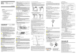
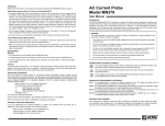
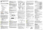
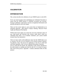
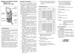
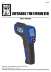
INSTRUCTION MANUAL
LEAKAGE CURRENT TESTER
KEW SNAP
Series
MODEL 2434
KYORITSU ELECTRICAL INSTRUMENTS WORKS, LTD.,
TOKYO, JAPAN
1. SAFETY WARNINGS
This instrument has been designed and tested according to IEC
Publication 61010: Safety Requirements for Electronic Measuring
Apparatus. This instruction manual contains warnings and safety
rules which must be observed by the user to ensure safe operation
of the instrument and to retain it in safe condition. Therefore, read
through these operating instructions before starting using the
instrument.
WARNING
●Read through and understand instructions contained in this
manual before starting using the instrument.
●Save and keep the manual at hand to enable quick reference
whenever necessary.
●Be sure to use the instrument only in its intended applications
and to follow measurement procedures described in the
manual.
●Be sure to understand and follow all safety instructions
contained in the manual.
Not following the above instructions may cause injury, instrument
damage and/or damage to equipment under test.
The symbol
indicated on the instrument means that the user
must refer to related parts of the manual for safe operation of the
instrument. Be sure to carefully read the instructions following
each
symbol in this manual.
DANGER is reserved for conditions and actions that are likely
to cause serious or fatal injury.
WARNING is reserved for conditions and actions that can
cause serious or fatal Injury.
CAUTION is reserved for conditions and actions that can cause
minor injury or Instrument damage.
DANGER
●Never make measurement on a circuit having potential of
300VAC or greater.
●Do not attempt to make measurement in the presence of
flammable gasses. Otherwise, the use of the instrument may
cause sparking, which leads to an explosion.
●The transformer jaws are made of metal and their tips are not
completely insulated. Be especially careful about the possible
shorting where the equipment under test has exposed metal
parts.
●Never attempt to use the instrument if its surface or your hand is
wet.
●D o n o t e x c e e d t h e m a x i m u m a l l o w a b l e i n p u t o f a n y
measurement range.
●Never open the battery compartment cover when making
measurement.
WARNING
●Never attempt to make any measurement, if any abnormal
conditions are noted, such as broken case, cracked test leads
and exposed metal parts.
●Do not install substitute parts or make any modification to the
instrument. Return the instrument to Kyoritsu or your distributor
for repair or re-calibration.
CAUTION
●Make sure that the range selector switch is set to an appropriate
position before making measurement.
●Do not expose the instrument to the direct sun, extreme
temperatures or dew fall.
●Be sure to set the range selector switch to the "OFF" position
after use. When the instrument will not be in use for a long
period of time, place it in storage after removing the batteries.
●Use a damp cloth and detergent for cleaning the instrument. Do
not use abrasives or solvents.
●Always switch off the instrument before opening the battery
compartment cover for battery replacement.
2. FEATURES
●Digital clamp tester for AC leakage current measurement.
●Least affected by external magnetic field, providing wide
measuring range from very small to large currents.
●Designed to safety standard IEC 61010-2-032: over-voltage CAT.Ⅲ,
300V and pollution degree 2.
●Data hold function to allow for easy readings in dimly lit or hard-toreach locations.
●Provides filtering function to remove high frequency generated by
such equipment as inverters.
●Sleep function prevents unnecessary power consumption.
●Dynamic range of 4000 counts full scale.
●Large easy-to-read LCD display with letter height of 13mm.
●Transformer jaws fitted with guard to further improve safety.
3. SPECIFICATIONS
Measuring ranges and accuracy
Range
Measuring Range
Accuracy (Frequency range)
400mA
0∼399.9mA
±2.0%rdg±4dgt(50/60Hz)
4A
0∼3.999A
±3.0%rdg±5dgt(40∼400Hz)
100A
0∼100.0A
When measuring current which pulse element is superposed, differences of
the indicated value may be caused between ranges, if the peak value
exceeds the measurement range to a large extent. In this case, the reading
at the bigger range should be taken as a right value.
Sensitive transformer jaws are used for Leakage clamp meter. Because of
the characteristics of transformer jaws, which can be opened and closed, it
is impossible to eliminate the interference of external magnetic field
completely. If there are something, which generating large magnetic field, at
a nearby site, current value can be displayed (“0” cannot be displayed.)
before clamping on the conductor. For such a case, please use the
instrument at a location far from the thing, which generating magnetic field.
Following are the typical things generating magnetic field.
Conductor fed large current, Motor, Equipment which has magnet,
Integrating wattmeter
Measuring method:
Display:
Low battery warning:
Overrange Indication:
Response Time:
Sample Rate:
Accuracy-insured
Temperature and
Humidity Ranges:
Operating Temperature
and Humidity Ranges:
Storage Temperature
and Humidity Ranges:
Power Source:
Current Consumption:
Measurement Time:
Sleep Function:
Safety Standard:
Overload Protection:
Withstand Voltage:
Insulation Resistance:
Conductor Size:
Dimensions:
Weight:
Accessories:
Optional Accessories:
Dual Integration
Liquid crystal display with maximum reading
of 3999
"BATT" mark appears on the display
"OL" appears on the display when upper limit
of measuring range is exceeded
Approx. 2 seconds
Approx. 2.5 times per second
23℃±5℃, relative humidity 85% or less
(without condensation)
0-40℃, relative humidity 85% or less
(without condensation)
-20-60℃, relative humidity 85% or less
(without condensation)
Two 1.5V R03 (UM-4) batteries
Approx. 4mA
Approx. 150 hours
Automatically powered down in about 10
minutes after the last switch operation
IEC 61010-1, IEC 61010-2-032
over-voltage CAT.Ⅲ 300V, pollution degree 2
IEC 61326 (EMC)
120Arms max. for 10 seconds
3700Vrms (50/60Hz) for 1 minute between
metal part of transformer jaws and housing
case (except transformer jaw case)
10MΩ or greater at 1000V between metal
part of transformer jaws and housing case
(except transformer jaw case)
Approx. 28mm in diameter max.
169(L)×75(W)×40(D)mm
Approx. 220g including batteries
Two R03 (UM-4) batteries
Carrying case Model 9052
Instruction manual
Multi-Tran Model 8004 and 8008
4. INSTRUMENT LAYOUT
T r i gger
T r a ns f or m J aw s
R ange S e le cto r S witch
Ha n d S tra p
Disp la y
●LCD
Low Battery Warning
Data Hold Button
Frequency Selector Button
Data Hold Indication
Frequency Response :
Wide
Frequency Response :
50/60Hz
Unit
5. PREPARATIONS FOR MEASUREMENT
5-1 Checking Battery Voltage
Set the Range Selector Switch to any position other than the OFF
position. If the marks on the display is clearly visible without "BATT"
mark showing, battery voltage is OK. If the display blanks or "BATT"
is indicated, replace the batteries according to section 8: Battery
Replacement.
NOTE
When the instrument is left powered on, the Sleep function
automatically shut the power off; The display blanks even if the
Range Selector Switch is set to a position other than the OFF
position in this state. To power on the instrument, turn the Range
Selector Switch or press any button. If the display still blanks, the
batteries are completely exhausted. Replace the batteries.
5-2 Checking Switch Setting
Make sure that the Range Selector Switch is set to the appropriate
range.
Also make sure that data hold function is not enabled. If
inappropriate range is selected, desired measurement cannot be
made.
6. OPERATING INSTRUCTIONS
DANGER
●In order to avoid possible shock hazard, never make measurement
on circuits having a potential of 300VAC or greater.
●The transformer jaws are made of metal and their tips are not
completely insulated. Be especially careful about the possible
shorting where the equipment under test has exposed metal parts.
●Never make measurement with the battery compartment cover
removed.
CAUTION
●Take sufficient care to not to apply shock, vibration or excessive
force to the jaw tips. Otherwise, precisely adjusted Transformer
Jaw tips will be damaged.
●When a foreign substance is stuck in the jaw tips or they cannot
properly engage, the transformer jaws do not fully close. In
such a case, do not release the jaw trigger abruptly or attempt
to close the transformer jaws by applying external force. Make
sure that the jaws close by themselves after removing the
foreign substance or making them free to move.
●The maximum size of a conductor to be tested is 28mm in
diameter. Accurate measurement cannot be made on a
conductor larger than this, because the transformer jaws cannot
fully close.
●When measuring large current, the transformer jaws may buzz.
This has no effect on the instrument's performance or safety.
6-1 Leakage Current Measurement
(1)Set the Range Selector Switch to the desired position. Current
to measure should be within the selected measuring range.
(2)Measuring out of balance leakage current (See Fig.1):
Clamp onto all conductors except a grounded wire. Measured
current value is shown on the display.
(3)Measuring earth leakage current (See Fig.2):
Clamp onto a grounded wire.Measured current value is shown on
the display.
Load
Load
3-phase 3-wire system
(In 4-wire system with neutral,
clamp onto all 4 wires)
Single-phase 2-wire system
(in 3-wire system with neutral,
clamp onto all 3 wires)
Fig. 1 Measuring out of balance leakage current
Load
Grounded wire
Fig.2 Measuring earth leakage current
6-2 How to Use Frequency Selector Button
When high frequencies from such equipment as inverters are
present in the circuit under test, the instrument measures AC
current of not only 50Hz or 60Hz of fundamental frequency but also
of these high frequencies and harmonics.
To eliminate the effect of such high frequency noise and measure
AC current of 50Hz or 60Hz fundamental frequency, a "high-cut"
filter circuit in incorporated into the instrument which works when
"50/60Hz" frequency response is selected with the Frequency
Selector Button. Cut-off frequency of the "high-cut" filter is about
160Hz with attenuation characteristic of approx. -24dB/octave.
When the Frequency Selector Button is pressed, "50/60Hz" mark is
shown on the left side of the display. When the Frequency Selector
Button is pressed again, frequency response is switched to WIDE
with "WIDE" mark shown on the display.
Output characteristic are shown in Fig.3.
Typical characteristic:
400mA/4A Range
0
Typical characteristic:
100A Range
ー10
ー20
ー30
10
20
50
Typical characteristic:
“WIDE”frequency response
;;;;
;;;;
;;;;
;;;;
;;;;
;;;;
;;;;
100%
Typical characteristic:
50%
“50/60Hz”frequency response
high-cut filter -24dB/oct
20%
10%
Percentage
Attenuation〔dB〕
10
5%
100 200
500 1k
Frequency〔Hz〕
2k
5k
Fig.3 Model 2434 Frequency Characteristic
Note:
Characteristic of -24dB/octiave means that signal magnitude
declines to about one sixteenth of that at the initial frequency when
frequency doubles. Model 2434 have the following two settings for
the Frequency Selector Button.
WIDE (40Hz-): Permits measurement of currents of fundamental
frequencies as well as currents of high frequencies
generated by such equipment as inverters
50/60Hz (40-approx.160Hz): Filters out high frequency currents and
measures current of fundamental
frequency only
Recently there has been increased use of power through inverters,
switching regulators, etc. When the high frequency noise from such
appliances leaks or flows into the ground through capacitors not
filtering completely, the earth leakage breaker may trip even though
there is no "actual" leakage. In such a case, the instrument do not
give leakage current reading if "50/60Hz" frequency response is
selected.
Take current readings with the 50/60Hz and WIDE frequency
responses respectively to make effective use of the Frequency
Selector Button.
6-3 Load Current Measurement
(1)Set the Range Selector Switch to the desired position. Current to
measure should be within the selected measuring range.
(2)Measuring load current (See Fig.4):
Press the jaw trigger to open the transformer jaws and close
them over one conductor only.Measured current value is shown
on the display.
Load
Fig.4 Measuring load current
7. OTHER FUNCTIONS
7-1 Sleep Function
This is a function to prevent the instrument from being left powered
on in order to conserve battery life.
The instrument automatically enters the Sleep (powered-down)
Mode about 10 minutes after the last switch operation.
To exit the Sleep Mode, press the Data Hold or Frequency Selector
Button or turn the Range Selector Switch to OFF, then to any other
position.
How to Exit the Sleep Mode:
Turn the Range Selector Switch from “OFF” to another position
with the Data Hold Button pressed. Then, “P.OFF” is shown on
the display. This disables the Sleep function and enables
continuous use of the instrument.
To enable the Sleep function, turn the Range Selector Switch back
to “OFF”, then to any other position.
Note:
The instrument consumes small amount of current in the Sleep
Mode. When the instrument is not in use, make sure to set the
Range Selector Switch to “OFF”.
7-2 Date Hold Function
This is a function to freeze the readings on the display. When the
Data Hold Button is pressed once, the current reading is held even
though current under test varies. "H" mark is shown on the upper
right corner of the display.
To exit the data hold mode, press the Data Hold Button again.
Note: When the Sleep function works while the instrument is in the
data hold mode, data hold is cancelled.
8. BATTERY REPLACEMENT
CAUTION
●Do not mix new and old batteries.
●Install batteries in the orientation as shown inside the battery
compartment, observing correct polarity.
●In order to avoid possible shock hazard, always set the Range
Selector Switch to the OFF position before trying to replace the
batteries
When the battery voltage warning mark "BATT" is shown on the
top left corner of the LCD, replace the batteries. Note that the
display blanks and "BATT" mark is not shown if the batteries are
completely exhausted.
(1)Set the Range Selector Switch to "OFF."
(2)Loosen the battery-compartmentBattery
cover-fixing screw on the lower Screw
Compartment
back of the instrument.
Cover
(3)Replace the batteries with two
new R03 (UM-4) 1.5V batteries.
(4)Put the battery compartment
cover back in place and tighten
Batteries
the screw.
Note: Use alkaline batteries to perform
measuring for long hours.
9. OPTIONAL ACCESSORIES
Model 8004 and 8008 (Multi-Tran)
These models help Model 2434 to measure current greater than
1000A or to make measurement on a large bus-bar or conductor.
(1)Set the Range Selector Switch to "100A".
(2)As shown, open the jaws and close them over the pickup coil
of Model 8004 or Model 8008.
(3)Clamp on a conductor with Model 8004 or Model 8008.
(4)Take the reading and multiply it by 10.
Transformer
jaws
Conductor
10
:
1
M-8004
M-8008
Pickup Coil
M-2434
Note: Model 8004 and Model 8008 cannot be used for leakage current
measurement. For detailed specifications, refer to the
instruction manual for Model 8004 or Model 8008.
M-8004
M-8008
Max. Conductor Size
Measuring
Range
60mm in diameter
100mm in diameter
Current Transformation
Ratio
0∼1000A
10:1