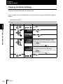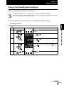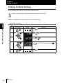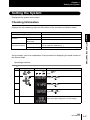
1
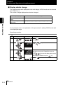
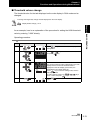
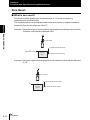
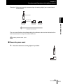
Displacement Sensor
Confocal Fiber Type
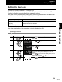
ZW Series
User’s Manual
Cat. No. Z322-E1-01A
Introduction
This manual provides information regarding functions, performance and operating methods that
are required for using the ZW Series.
• The ZW Displacement Sensor must be operated by personnel knowledgeable in electrical
engineering.
• To ensure correct use, please read this manual thoroughly to deepen your understanding of the
product.
• Please keep this manual in a safe place so that it can be referred to whenever necessary.
Chapter 1 㪤㪜㪘㪪㪬㪩㪜㪤㪜㪥㪫㩷㪪㪜㪫㪬㪧
Chapter 2 㪙㪘㪪㪠㪚㩷㪦㪧㪜㪩㪘㪫㪠㪦㪥
Chapter 3 㪪㪜㪫㪫㪠㪥㪞㪪㩷㪝㪦㪩㩷㪝㪬㪥㪚㪫㪠㪦㪥㪪
Chapter 4 㪠㪆㪦㩷㪪㪜㪫㪫㪠㪥㪞㪪
Chapter 5 㪜㫋㪿㪼㫉㫅㪼㫋㪆㪩㪪㪄㪉㪊㪉㪚㩷㪚㪦㪤㪤㪬㪥㪠㪚㪘㪫㪠㪦㪥
Chapter 6 㪪㪧㪜㪚㪠㪝㪠㪚㪘㪫㪠㪦㪥㪪㩷㪘㪥㪛㩷㪜㪯㪫㪜㪩㪥㪘㪣㩷㪛㪠㪤㪜㪥㪪㪠㪦㪥㪪
Chapter 7 㪘㪧㪧㪜㪥㪛㪠㪯
User's Manual
Confocal Fiber Displacement Sensor
ZW Series
Introduction
䈲 䈛 䉄䈮 Chapter
╙㩷㪈㩷┨ 1 Chapter
╙㩷㪉㩷┨ 2 Chapter
╙㩷㪊㩷┨ 3 Chapter
╙㩷㪋㩷┨ 4 Chapter 5 Chapter 6 Chapter 7
INTRODUCTION 㪘㪧㪧㪣㪠㪚㪘㪫㪠㪦㪥㩷㪚㪦㪥㪪㪠㪛㪜㪩㪘㪫㪠㪦㪥㪪㩷㩿㪧㫃㪼㪸㫊㪼㩷㪩㪼㪸㪻㪀
Introduction
Introduction
READ AND UNDERSTAND THIS DOCUMENT
Please read and understand this document before using the products. Please consult your OMRON
representative if you have any questions or comments.
WARRANTY
OMRON’s exclusive warranty is that the products are free from defects in materials and workmanship for
a period of one year (or other period if specified) from date of sale by OMRON.
OMRON MAKES NO WARRANTY OR REPRESENTATION, EXPRESS OR IMPLIED, REGARDING
NON-INFRINGEMENT, MERCHANTABILITY, OR FITNESS FOR PARTICULAR PURPOSE OF THE
PRODUCTS. ANY BUYER OR USER ACKNOWLEDGES THAT THE BUYER OR USER ALONE HAS
DETERMINED THAT THE PRODUCTS WILL SUITABLY MEET THE REQUIREMENTS OF THEIR
INTENDED USE. OMRON DISCLAIMS ALL OTHER WARRANTIES, EXPRESS OR IMPLIED.
LIMITATIONS OF LIABILITY
OMRON SHALL NOT BE RESPONSIBLE FOR SPECIAL, INDIRECT, OR CONSEQUENTIAL
DAMAGES, LOSS OF PROFITS OR COMMERCIAL LOSS IN ANY WAY CONNECTED WITH THE
PRODUCTS, WHETHER SUCH CLAIM IS BASED ON CONTRACT, WARRANTY, NEGLIGENCE, OR
STRICT LIABILITY.
In no event shall responsibility of OMRON for any act exceed the individual price of the product on which
liability is asserted.
IN NO EVENT SHALL OMRON BE RESPONSIBLE FOR WARRANTY, REPAIR, OR OTHER CLAIMS
REGARDING THE PRODUCTS UNLESS OMRON’S ANALYSIS CONFIRMS THAT THE PRODUCTS
WERE PROPERLY HANDLED, STORED, INSTALLED, AND MAINTAINED AND NOT SUBJECT TO
CONTAMINATION, ABUSE, MISUSE, OR INAPPROPRIATE MODIFICATION OR REPAIR.
SUITABILITY FOR USE
THE PRODUCTS CONTAINED IN THIS DOCUMENT ARE NOT SAFETY RATED. THEY ARE NOT
DESIGNED OR RATED FOR ENSURING SAFETY OF PERSONS, AND SHOULD NOT BE RELIED
UPON AS A SAFETY COMPONENT OR PROTECTIVE DEVICE FOR SUCH PURPOSES.
Please refer to separate catalogs for OMRON’s safety rated products.
OMRON shall not be responsible for conformity with any standards, codes, or regulations that apply to
the combination of products in the customer’s application or use of the product.
At the customer’s request, OMRON will provide applicable third party certification documents identifying
ratings and limitations of use that apply to the products. This information by itself is not sufficient for a
complete determination of the suitability of the products in combination with the end product, machine,
system, or other application or use.
The following are some examples of applications for which particular attention must be given. This is not
intended to be an exhaustive list of all possible uses of the products, nor is it intended to imply that the
uses listed may be suitable for the products:
• Outdoor use, uses involving potential chemical contamination or electrical interference, or conditions or
uses not described in this document.
2
ZW
User's Manual
Introduction
Introduction
• Nuclear energy control systems, combustion systems, railroad systems, aviation systems, medical
equipment, amusement machines, vehicles, safety equipment, and installations subject to separate
industry or government regulations.
• Systems, machines, and equipment that could present a risk to life or property.
Please know and observe all prohibitions of use applicable to the products.
NEVER USE THE PRODUCTS FOR AN APPLICATION INVOLVING SERIOUS RISK TO LIFE OR
PROPERTY WITHOUT ENSURING THAT THE SYSTEM AS A WHOLE HAS BEEN DESIGNED TO
ADDRESS THE RISKS, AND THAT THE OMRON PRODUCT IS PROPERLY RATED AND INSTALLED
FOR THE INTENDED USE WITHIN THE OVERALL EQUIPMENT OR SYSTEM.
PERFORMANCE DATA
Performance data given in this document is provided as a guide for the user in determining suitability and
does not constitute a warranty. It may represent the result of OMRON’s test conditions, and the users
must correlate it to actual application requirements. Actual performance is subject to the OMRON
Warranty and Limitations of Liability.
CHANGE IN SPECIFICATIONS
Product specifications and accessories may be changed at any time based on improvements and other
reasons.
It is our practice to change model numbers when published ratings or features are changed, or when
significant construction changes are made. However, some specifications of the product may be
changed without any notice. When in doubt, special model numbers may be assigned to fix or establish
key specifications for your application on your request. Please consult with your OMRON representative
at any time to confirm actual specifications of purchased products.
DIMENSIONS AND WEIGHTS
Dimensions and weights are nominal and are not to be used for manufacturing purposes, even when
tolerances are shown.
ERRORS AND OMISSIONS
The information in this document has been carefully checked and is believed to be accurate; however, no
responsibility is assumed for clerical, typographical, or proofreading errors, or omissions.
PROGRAMMABLE PRODUCTS
OMRON shall not be responsible for the user’s programming of a programmable product, or any
consequence thereof.
COPYRIGHT AND COPY PERMISSION
This document shall not be copied for sales or promotions without permission.
This document is protected by copyright and is intended solely for use in conjunction with the product.
Please notify us before copying or reproducing this document in any manner, for any other purpose. If
copying or transmitting this document to another, please copy or transmit it in its entirety.
ZW
User’s Manual
3
Introduction
Meanings of Signal Words
Introduction
Meanings of Signal Words
The following signal words are used in this manual.
Warning
Caution
Indicates a potentially hazardous situation which, if not avoided, will
result in minor or moderate injury, or may result in serious injury or
death. Additionally there may be significant property damage.
Indicates a potentially hazardous situation which, if not avoided, may
result in minor or moderate injury or in property damage.
Meanings of Alert Symbols
The following alert symbols are used in this manual.
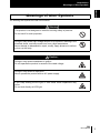
Indicates general prohibitions for which there is no specific symbol.
Indicates prohibition when there is a risk of minor injury from electrical
shock or other source if the product is disassembled.
Indicates the possibility of fire under specific conditions.
Indicates the possibility of explosion under specific conditions.
Indicates the possibility of LED radiation.
4
ZW
User's Manual
Introduction
Meanings of Alert Symbols
Introduction
Meanings of Alert Symbols
The following alert symbols are used in this manual.
Warning
This product is not designed or rated for ensuring safety of persons.
Do not use it for such purposes.
Doing so may cause high-voltage section to be exposed, resulting in the
electrical shock, and may cause burn from a high temperature.
Never attempt to disassemble, repair, modify, apply pressure to deform
or burn up the body.
Caution
Doing so may cause breakdown or ignition.
Do not operate the product in excess of the rated voltage.
Doing so may cause an explosion.
Never operate the product with an AC power supply.
If you keep looking at LED light, in rare cases visual impairment may
occur.
Do not look directly at LED light.
ZW
User’s Manual
5
Introduction
Precautions for Safe Use
Introduction
Precautions for Safe Use
Please observe the following precautions for safe use of the products.
(1) Installation Environment
• Do not use the product in environments where it can be exposed to inflammable/
explosive gas.
• To secure the safety of operation and maintenance, do not install the product close to
high-voltage devices and power devices.
(2) Power Supply and Wiring
• Take care when using a power supply with an overcurrent detector, because this
sensor uses DC-DC converter for its power supply circuit and inrush current may
activate the protective circuit for a power supply with an overcurrent detector.
Recommended power supply: S8VS-06024 (Omron, DC24 V 2.5 A 60 W)
• The supply voltage must be within the rated range (DC24 V ± 10 %).
• Reverse connection of the power supply is not allowed.
• Open-collector outputs should not be short-circuited.
• Use the power supply within the rated load.
• High-voltage lines and power lines must be wired separately from this product. Wiring
them together or placing them in the same duct may cause induction, resulting in
malfunction or damage.
• Use adequate safety measures, for example fail-safe circuits.
• Attach a specified-sized crimp-type terminal at the end of a wire. Do not connect a
wire with an only twisted end directly to a power supply or terminal block.
• For a power supply, use a DC power supply unit provided with a remedy, for example,
safety ultralow voltage circuit, to prevent a high voltage from being generated.
• Route so that power supply wires are as short as possible.
• Use D-type grounding (ground resistance of 100 or less). Make the ground point as
close as possible and make the ground wire used as short as possible.
• Never a ground wire with other equipment and never ground to building beams. Doing
so could cause negative impacts.
• Use a power supply dedicated for this product, without sharing it with other products.
• Tighten fixing screws securely at a torque specified in this manual.
• Before performing any of the following activities, be sure to turn off the product, or
breakdown may result.
- Connecting or wiring cables
- Connecting or disconnecting connectors
- Installing or removing Calibration ROM
(3) Others
• Do not use this product for nuclear facilities, or safety circuits involving human lives.
• Do not attempt to disassemble, repair, modify, apply pressure to deform or burn up the
body.
• Dispose of this product as industrial waste.
6
ZW
User's Manual
Introduction
Precautions for Safe Use
Introduction
• Use exclusive devices, including a sensor head, Calibration ROM, fiber cable or RS232C cable, to connect, or ignition, burst, false operation or breakdown may be
caused.
•Do not cut fiber cable. Glass at the cut section may cause injury. Also, if cut, it will not
work normally anymore.
• Whenever any trouble, including, strange odor smelled, the body overheated or
smoke escaped, was found, immediately stop the operation, and consult an OMRON
branch or sales office with the system shut down.
• Do not drop or make a strong impact on the unit.
• Before using any equipment provided with a lock mechanism, make sure that it has
been locked.
(4) Regulations and Standards
This sensor conforms to the following EMC directive and EN standard:
• EMC directive, No. 2004, 108, EC
• EN standard, EN61326
(5) Notice for Korea Radio Law
匏͑匶匶 ా櫋怺殯͑愯暧皻柦匶沖沲ి
決͑匶匶垚͑櫋怺殯 ͙ 匏 ͚͑洊沖砒洇穯匶匶嵢昢͑砖廪沖
嬖垚͑斲殯沖垚͑決͑洖汊͑渂汞穞柢匶͑愚岂彶 ͝ 儆洛歾汞
滆櫳櫖昢͑斲殯穞垚͑冉汊͑徯洇求嵢͑穯城埪͟
ZW
User’s Manual
7
Introduction
Precautions for Correct Use
Introduction
Precautions for Correct Use
Please observe the following precautions to prevent failure to operate, malfunctions, or undesirable
effects on product performance.
(1) Installation Site
Do not install the product in locations subjected to the following conditions:
• Ambient temperature outside the rating
• Rapid temperature fluctuations (causing condensation)
• Relative humidity outside the range of 35 to 85 %
• Presence of corrosive or flammable gases
• Presence of dust, salt, or iron particles
• Direct vibration or shock
• Reflection of intense light (such as other laser beams, electric arc-welding machines
or ultraviolet shine)
• Direct sunlight or near heaters
• Water, oil, or chemical fumes, spray or mist atmospherics
• Strong magnetic or electric field
(2) Power Supply and Wiring
• When using a commercially available switching regulator, make sure that the FG
terminal is grounded.
• If surge currents are present in the power lines, connect surge absorbers that suit the
operating environment.
• Before turning ON the power after the product is connected, make sure that the power
supply voltage is correct, there are no incorrect connections (e.g. load short-circuit)
and the load current is appropriate. Incorrect wiring may result in breakdown of the
product.
• Use the specified voltage. If voltage exceeding the rating or AC voltage is applied,
circuit parts may be burnt or rupture.
• Use the Extension Fiber Cable (ZW-XF_ _R) for extending the fiber cable between
the Sensor extension fiber cable, five total lengths, 2, 5, 10, 20 or 30 m, are available.
• Handling fiber cables
Use them in compliance with the following.
-Fiber cable bend radiuses must be at least 20 mm.
- Do not let bending cause stress at the root section of a fiber connector.
-Do not yank hard on a fiber cable.
-Do not step on a fiber cable or place anything heavy on it.
• Be sure to use a Sensor Head and Calibration ROM with the same serial number. A
pair with different serial numbers cannot operate normally.
• Use the configuration software with the combination specified in this manual, or the
system may operate faultily.
• Do not shut down the power supply when saving any data into the memory built in the
controller, or the data may be corrupted.
8
ZW
User's Manual
Introduction
Precautions for Correct Use
Introduction
• While a fiber cable is disconnected, be sure to attach the included protective cap on
both the controller side and the fiber cable side. Leaving the fiber cable with the
protective cap not attached, the optical fiber may fail due to any adhered foreign
matter.
(3) Warming Up
After turning ON the power supply, allow the product to stand for at least 30 minutes
before use. The circuits are still unstable immediately after the power supply is turned
ON, so measured values may fluctuate gradually.
(4) Maintenance and Inspection
Do not use thinner, benzene, acetone or kerosene to clean the Sensor Head, fiber
cable and controller. If large dust particles adhere to the emitter/receiver of the Sensor
Head or controller, use a blower brush (used to clean camera lenses) to blow them off.
Do not blow the dust particles with your mouth.
To remove smaller dust particles, dirt, oil, and fat, wipe gently with a soft cloth (for
cleaning lenses). Do not use excessive force to wipe off dust particles. Scratches on
the emitter/receiver may cause false operations or measuring errors.
For details on the method for cleaning the ends of fiber cables, refer to "Connecting
Fiber Cables" (p.1-15).
(5) Sensing Objects
The product sometimes cannot accurately measure the following types of objects:
Transparent objects, objects with an extremely low reflection factor, objects smaller
than the spot diameter, objects with a large curvature, excessively inclined objects,
target objects with a thin film on the surface etc.
(6) Effect caused by peripheral lights
Do not install the Sensor Head in a place where strong light hits the laser emitter/
receiver section of the Sensor Head. Also, if a workpiece has a shiny surface, the light
from the lighting will be reflected and a malfunction may occur. In such a case, prevent
reflection by, for example, covering the light to stop reflection.
p.1-8
(7) Influence by Air Turbulences
Slow air turbulences around the Sensor Head may disperse measured values.
To avoid these possible air turbulences, wrap the Sensor Head with an appropriate
cover.
ZW
User’s Manual
9
Introduction
Editor's Note
Introduction
Editor's Note
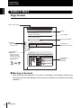
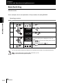
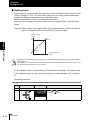
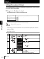
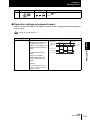
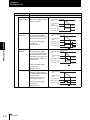
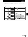
Page Format
╙㪋┨ 䇭 㪠㪆㪦⸳ቯ
ജ䈮㑐䈜䉎⸳ቯ
Title of each chapter
ജ䈮㑐䈜䉎⸳ቯ
Chapter 4
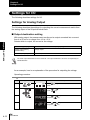
Settings for I/O
Settings for I/O
Header
The following describes settings for I/O.
Settings for Analog Output
Cross-header
╙㩷 㩷┨
The following describes the settings for outputting the current measurement results from
the analog output of the 20-pole terminal block.
Output destination setting
Indicates the chapter
number and title.
Chapter 4 I/O SETTINGS
Index label
With analog output, the measurement results can be output converted into a current
from 4 to 20 mA or a voltage from -10 to +10 V.
Selects which to output, the current or the voltage.
Setting [Display]
Description [Display]
Voltage output [VOLT]
(Default value)
Voltage output
Current output [CUR.]
Current output
Quasi Cross-header
Explanation of
Explanation of options
The same output destination is set for all banks. The output destination cannot be set separately for
individual banks.
Supplementary
Explanation
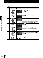
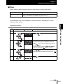
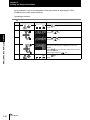
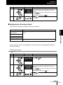
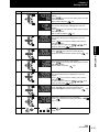
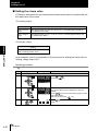
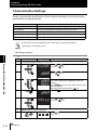
As an example, here is an explanation of the procedure for outputting the voltage.
Operating procedure
Helpful information
regarding operation
and reference pages
are introduced here
using symbols.
Steps
1
Key operation
LTEACH
2
Display
RUN
FUN
ZERORST/ ESC
3
ZERO/ SET
H
L
Description
UNLIT
Press
RUN
mode.
RUN
key for two seconds to enter the FUN
FUN
LTEACH
Press
press
ZERO/ SET
or
key.
Press
or
and press
keys to select either of "ANALOG"
key.
Press
or
and press
keys to select either of "V OR C"
key.
ZERO/ SET
4
ZERO/ SET
4-12
keys to select either of "I/O" and
Explanation of
Operating
procedure
ZW
User’s Manual
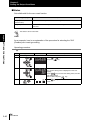
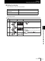
■ Meaning of Symbols
Menu items that are displayed on the main or sub-display, and windows, dialog boxes
and other GUI elements displayed on the personal computer are indicated enclosed by
brackets [ ].
10
ZW
User’s Manual
Introduction
Editor's Note
Introduction
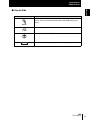
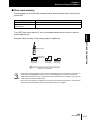
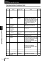
■ Visual Aids
Mark
Means
Indicates points that are important to ensure full product performance, such as operational precautions and application procedures.
Indicates pages where related information can be found.
Indicates information helpful in operation.
Optional
Indicates that the setting is optional in a configuration procedure.
ZW
User’s Manual
11
Introduction
Editor's Note
Introduction
Notice
•Photocopying, duplication, or copying of all or part of this manual without permission is
prohibited.
•Please understand that the specifications and other contents of this manual are subject to change for improvement without notice.
•Every effort has been made to ensure the accuracy of the contents of this manual, but
if you should notice any mistake, questionable section, or the like in this manual,
please contact an OMRON branch or sales office.
•If you do so, please also tell us the manual number, which is found at the end of the
manual.
12
ZW
User’s Manual
Introduction
Related Manuals
Introduction
Related Manuals
The following manual is related to the ZW series. Use this manual for reference.
Manual name
Smart Monitor ZW
Operation manual
Cat. No.
Model
numbers
Z323-E1-01 ZW-SW_ _
Application
Description
This describes the
To learn about the
operation methods and operation methods for
functions of the Smart the Smart Monitor ZW.
Monitor ZW
ZW
User’s Manual
13
Introduction
Related Manuals
Introduction
14
ZW
User’s Manual
Introduction
Meanings of Signal Words
4
Meanings of Alert Symbols
4
Meanings of Alert Symbols
5
Precautions for Safe Use
6
Precautions for Correct Use
8
Editor's Note
10
Page Format
10
Notice
12
Related Manuals
Search from Menu Tree
Section 1 MEASUREMENT SETUP
13
20
1-1
System Configuration
1-2
Part Names and Functions
1-3
Sensor Head
1-3
Calibration ROM
1-3
Controller
1-4
About Installation and Connection
1-7
Installation of Sensor Head
1-7
Installation of Controller
1-10
Connecting Calibration ROM
1-14
Connecting Fiber Cable
1-15
Calibrating Sensor Head
1-19
Smart Monitor ZW
1-21
Operating Environment
1-22
Installation/Uninstallation Method
1-23
Settings when Connecting Personal Computer with Controller
1-25
Starting and Exiting
1-29
Section 2 BASIC OPERATION
Overview of Setting and Measurement
Operation Modes
CONTENTS Section 1 Section 2 Section 3 Section 4 Section 5 Section 6 Section 7 Section 8 Section 9
CONTENTS
2-1
2-2
2-2
ZW
User’s Manual
15
Introduction
CONTENTS
Functions of Operating Keys
2-3
Digital Displays
2-4
Multi-task and Bank Data
2-6
Setting Flow
Functions and Operations during Measurement
2-10
Switching the Display during RUN mode
2-10
Zero Reset
2-14
Setting Threshold Value
2-17
Bank Switching
2-20
Section 3 SETTINGS FOR FUNCTIONS
Setting Sensing
3-1
3-2
Setting the Material for the Target to Measure
3-2
Setting Exposure Time Control Mode
3-3
Setting Measurement Items
3-5
Measuring the Height
3-6
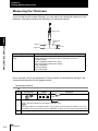
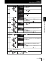
Measuring the Thickness
3-8
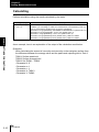
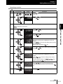
Calculating
Setting the Output Conditions
3-10
3-14
Setting the Filter
3-14
Setting the Scaling
3-21
Setting the Hold
3-28
Setting the Zero Reset
3-37
Setting the Banks
3-43
Changing the Bank Mode
3-43
Copying the Bank Settings
3-44
Saving the Bank/System Settings
3-45
Clearing the Bank Settings
3-46
Setting the System
16
2-8
3-47
Checking Information
3-47
Setting the Key Lock
3-49
Initializing Settings
3-50
ZW
User’s Manual
Introduction
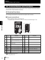
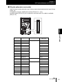
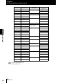
I/O Terminal Names and Functions
4-1
4-2
I/O Terminal Functions
4-2
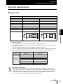
Electrical Specifications
4-5
I/O Signal Functions
Settings for I/O
4-7
4-12
Settings for Analog Output
4-12
Settings for Judgment Output
4-18
Settings for Binary Output
4-22
Settings for Processing when Measurement Cannot be Performed
4-28
Settings for I/O Signals
4-31
Timing Charts
Section 5 Ethernet/RS-232C COMMUNICATION
Overview
4-33
5-1
5-2
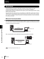
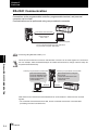
Ethernet Communication
5-2
RS-232C Communication
5-4
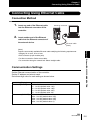
Connecting Using Ethernet Cable
5-5
Connection Method
5-5
Communication Settings
5-5
Connecting Using RS-232C Cable
Connection Method
5-7
5-7
Communication Settings
5-10
Communication Command List
5-12
Command format
5-14
Section 6 SPECIFICATIONS AND EXTERNAL DIMENSIONS
Sensor Head
6-1
6-2
Specifications
External Dimensions
6-3
Spot Diameter
6-4
Linearity Characteristic by Materials
6-5
Angle Characteristic
6-6
Controller
CONTENTS Section 1 Section 2 Section 3 Section 4 Section 5 Section 6 Section 7 Section 8 Section 9
Section 4 I/O SETTINGS
6-8
ZW
User’s Manual
17
Introduction
CONTENTS
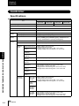
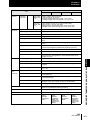
Specifications
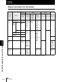
Status Indicators for Controller
6-10
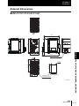
External Dimensions
6-11
Accessories
6-12
Extension Fiber Cable
6-12
Connecting Adapter (For Fiber Cable Connection)
6-13
RS-232C Cable
6-14
Parallel Cable
6-15
Section 7 APPENDIX
7-1
Troubleshooting
7-2
Error Messages and Countermeasures
7-5
EMC Directive Conformity
7-7
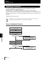
Updating Firmware
7-8
Flow of Updating Firmware
18
7-8
Processing Item Data List
7-13
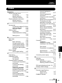
Index
7-19
Revision History
7-23
ZW
User’s Manual
Introduction
CONTENTS
ZW
User’s Manual
19
Introduction
CONTENTS
CONTENTS
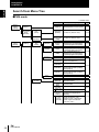
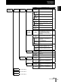
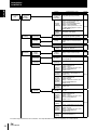
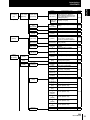
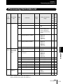
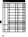
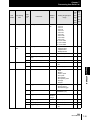
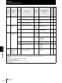
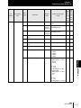
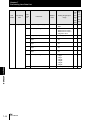
Search from Menu Tree
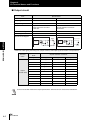
■FUN mode
* - Default value
Sensing
setting
[SENS]
Material
[OBJECT]
Exposure
Time Control
Mode
[EXPOSE]
Auto *
[AUTO]
Manual
[MANUAL]
Measurement
setting
[MEAS]
TASK1
[TASK1]
Measurement
item
[ITEM]
Height
[HEIGHT]
Thick
[THICK]
Setting
Option/Setting range
Pages
Material
[OBJECT]
Normal [NORMAL] */Mirror surface
[MIRROR]/Diffusion surface [DIFF]
p.3-2
Upper limit
[UPPER]
1 to 5000 ms (Default: 1000)
p.3-3
Fixed
exposure time 1 to 5000 ms (Default: 1000)
[TIME]
p.3-3
Measurement Edge 1st [EDGE1]/Edge 2nd
[EDGE2]/Edge 3rd [EDGE3]/Edge
Surface
[SUR]
4th [EDGE4]/Light Peak [PEAK] *
p.3-6
Edge 1st [EDGE1]/Edge 2nd
[EDGE2]/Edge 3rd [EDGE3]/Edge
4th [EDGE4]/Light Peak [PEAK] *
Edge 1st [EDGE1]/Edge 2nd
[EDGE2]/Edge 3rd [EDGE3]/Edge
4th [EDGE4]/Light Peak [PEAK] *
p.3-8
Surface 1
[TOP]
Surface 2
[END]
Calculation
[CALC]
Parameter K
[PARAM.K]
Parameter m
[PARAM.M]
Parameter n
[PARAM.N]
Parameter X
[PARAM.X]
Parameter Y
[PARAM.Y]
None
[NONE]
Filter
[FILTER]
Median
[MEDIAN]
Average
[AVE]
Differ
[DIFFER]
Differ cycle
[CYCLE]
-999.999999 to 999.999999 mm
(Default: 0)
-10.0 to 10.0 (Default: 0)
-10.0 to 10.0 (Default: 0)
None [OFF] */TASK1 [TASK1]/
TASK2 [TASK2]/TASK3 [TASK3]/
TASK4 [TASK4]
None [OFF] */TASK1 [TASK1]/
TASK2 [TASK2]/TASK3 [TASK3]/
TASK4 [TASK4]
OFF [OFF] */LOW [LOW]/MID
[MID]/HIGH [HIGH]
1/2/4/8/16/32/64/128/256*/512/
1024/2048/4096
p.3-10
p.3-5
p.3-15
p.3-16
Off [OFF] */On [ON]
p.3-17
1 to 5000 ms (Default: 1)
OFF [OFF] */Lowpass [LOPASS]/
Highpass [HIPASS]/Bandpass
[BDPASS]
Lowpass/Highpass: 0.001 to
Cutoff
999.999 Hz (Default: 0.001)
frequency Bandpass: 0.001 to 999.999 Hz
[CUTOFF] (Default: Upper limit 999.999/
Lower limit: 0.001)
Frequency
[FREQ]
20
ZW
User's Manual
p.3-19
Introduction
CONTENTS
Measurement
setting
[MEAS]
(Cont'd)
TASK1
[TASK1]
Output
[OUTPUT]
Scaling
[SCALE]
(Cont'd)
Auto
[AUTO]
One-point
scaling
[1PT]
Direction
[DIR]
Two-point
scaling
[2PT]
Manual
[MANUAL]
Span
[SPAN]
Offset
[OFFSET]
Thick
[THICK]
Off
[OFF] *
Hold
[HOLD]
Type
[TYPE]
Trigger
[TRIG]
Trigger
level
[LEVEL]
Option/Setting range
Pages
-
Forward [FWD] */Reverse [REV]
p.3-21
-2.0000 to 2.0000 (Default: 1.0000)
-999.999999 to 999.999999 mm
(Default: 0)
Off [OFF] */Peak [PEAK]/Bottom
[BOTTOM]/Peak to peak [P-P]/Auto
peak [AUTOPK]/Auto bottom
p.3-28
[AUTOBT]/Auto peak to peak
[AUTOPP]/Average [AVE]/Sample
[SAMPLE]
Timing [TIMING] */Selfup trigger
[SELF-U]/Selfdown trigger [SELFD]
-999.999999 to 999.999999 mm
(Default: 0)
to 999.999999mm
Trigger hys 0
(Default: 0.05 % of measurement
[HYS]
range)
Delay
Off [OFF] */On [ON]
[DELAY]
Delay time 1 to 5000 ms (Default: 1 ms)
[DLY.TIM]
Sampling
time
1 to 5000 ms (Default: 100 ms)
[SMP.TIM]
Zero reset
[ZERO]
Threshold
[JUDGE]
Teaching
[TEACH]
Direct
[DIRECT]
TASK2
[TASK2]
(same as TASK1)
TASK3
[TASK3]
(same as TASK1)
TASK4
[TASK4]
(same as TASK1)
Type
[TYPE]
Offset
[OFFSET]
Status
[STATUS]
Real value [REAL] */Hold value
[HOLD]
-999.999999 to 999.999999 mm
(Default: 0)
p.3-32
p.3-35
p.3-37
p.3-39
p.3-40
Off [OFF]/On [ON] *
High
threshold
[H.JUDGE]
-999.999999 to 999.999999 mm
(Default: +25 % of measurement
range)
-999.999999 to 999.999999 mm
Low threshold (Default: -25 % of measurement
[L.JUDGE]
range)
High
threshold
[H.JUDGE]
CONTENTS
Setting
-999.999999 to 999.999999 mm
(Default: +25 % of measurement
range)
-999.999999 to 999.999999 mm
Low threshold (Default: -25 % of measurement
[L.JUDGE]
range)
p.2-18
p.2-19
ZW
User’s Manual
21
Introduction
CONTENTS
CONTENTS
Setting
I/O setting
[I/O]
Non
measurement
setting
[HLD.RST]
Judgment
[JUDGE]
Non
measurement
Keep [KEEP]/Clamp [CLAMP] *
setting
[HLD.RST]
Current output: MIN [MIN]
(Approx. 3.4 mA)/4 mA/5 mA/.../19
mA/20 mA/MAX [MAX]
Analog
(Approx. 21 mA) (Default: MAX)
output
[ANALOG] Voltage output: MIN [MIN]
(Approx. -10.8 V)/-10 V/-9 V/.../9 V/
10 V/MAX [MAX] (Approx. 10.8 V)
(Default: MAX)
Binary
output
MAX [MAX] */MIN [MIN]
[BINARY]
Output object
[OUTPUT]
Hysteresis
[HYS]
Timer
[TIMER]
Analog output
[ANALOG]
Option/Setting range
Voltage or
current *
[V OR C]
Output object
[OUTPUT]
Focus
[FOCUS]
Output object TASK1 [TASK1] */TASK2 [TASK2]/
[OUTPUT]
TASK3 [TASK3]/TASK4 [TASK4]
Hysteresis
[HYS]
0 to 99.9999 mm
(Default: 0.05 % of measurement
range)
Timer
Off* [OFF]/Off delay [OFF.DLY]/On
[TIMER]
delay [ONDLY]/1 shot [1SHOT]
Timer time
1 to 5000 ms (Default: 1)
[TIME]
Voltage or
current
[V OR C]
Voltage output */Current output
*
Output object OFF [OFF]/TASK1 [TASK1] /
TASK2 [TASK2]/TASK3 [TASK3]/
[OUTPUT]
TASK4 [TASK4]
Focus
[FOCUS]
Focus
Current/
Voltage 1
[CUR1]/
[VOLT1]
Pages
p.4-28
p.4-30
p.4-18
p.4-18
p.4-19
p.4-12
p.4-13
Off [OFF] */On [ON]
Current: 4/5/6/7/8/9/10/11/12/13/14/
15/16/17/18/19/20 mA
(Default: 4 mA)
Voltage: -10/-9/-8/-7/-6/-5/-4/-3/-2/1/0/1/2/3/4/5/6/7/8/9/10 V
(Default: -10 V)
Measurem
to 999.999999 mm
ent value 1 -999.999999
p.4-14
(Default: -0.5)
[MEAS1]
Current: 4/5/6/7/8/9/10/11/12/13/14/
Focus
Current/ 15/16/17/18/19/20 mA
Voltage 2 (Default: 20 mA)
Voltage: -10/-9/-8/-7/-6/-5/-4/-3/-2/[CUR2]/
[VOLT2] 1/0/1/2/3/4/5/6/7/8/9/10 V
(Default: 10 V)
Measurem
to 999.999999 mm
ent value 2 -999.999999
(Default: 0.5)
[MEAS2]
Calibration
[CALIB]
Calibration
[CALIB]
Calibration
Current/
Voltage 1
[CUR1]/
[VOLT1]
Off * /On
Current: 4/5/6/7/8/9/10/11/12/13/14/
15/16/17/18/19/20 mA
(Default: 4 mA)
Voltage: -10/-9/-8/-7/-6/-5/-4/-3/-2/1/0/1/2/3/4/5/6/7/8/9/10 V
(Default: -10 V)
Calibration
value 1
-999 to 999 (Default: 0)
p.4-16
[ADJ1]
Current:
4/5/6/7/8/9/10/11/12/13/14/
Calibration
15/16/17/18/19/20 mA
Current/
Voltage 2 (Default: 20 mA)
Voltage: -10/-9/-8/-7/-6/-5/-4/-3/-2/[CUR2]/
1/0/1/2/3/4/5/6/7/8/9/10 V
[VOLT2]
(Default: 10 V)
Calibration
value 2
-999 to 999 (Default: 0)
[ADJ2]
*
22
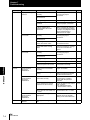
The same output destination is set for all banks. The output destination cannot be set separately for individual banks.
ZW
User's Manual
Introduction
CONTENTS
I/O setting
[I/O]
Binary output
[BINARY]
System
setting
[SYSTEM]
Pages
Measurement value 1 [MEAS1]
(TASK1(ON*/OFF), TASK2 to
Output object
TASK4
(ON/OFF*))/Measurement
[OUTPUT]
value 2 [MEAS2]/Judgment value
[JUDGE]/Off [OFF] *
TASK1 to 4
[TASK1] to Off [OFF] */On [ON]
[TASK4]
p.4-22
Decimal point
digit
[DEC.NUM]
Decimal point
0 [0DIG] to 6 [6DIG] (Default: 5
digit
[5DIG])
[DEC.NUM]
p.4-25
Output cycle
[CYCLE]
Output cycle
[CYCLE]
p.4-26
GATE Period
[GATE]
GATE Period
0.1 to 100.0 ms (Default: 0.1)
[GATE]
p.4-27
Bank change
[BK.CHG]
BANK1 [BANK1] to BANK8
Bank number [BANK8] (Default: BANK1)
[BANK]
If bank mode is "Judge mode",
selection is possible to BANK32.
p.2-20
Normal mode [NORMAL] */Judge
mode [JUDGE]
p.3-43
BANK1 [BANK1] to BANK8
[BANK8]
BANK1 [BANK1] to BANK8
[BANK8]
p.3-44
Output object
[OUTPUT]
(Cont'd)
Bank setting
[BANK]
Option/Setting range
1 to 100 (Default: 1)
Bank mode
[BK.MODE]
Bank mode
[BK.MODE]
Bank copy
[BK.COPY]
From
[FROM]
To
[TO]
Bank clear
[BK.CLR]
Bank clear
[BK.CLR]
OK [OK]/Cancel [CAN]
p.3-46
Save
[SAVE]
Save
[SAVE]
OK [OK]/Cancel [CAN]
p.3-45
Initialize
[INIT]
Initialize
[INIT]
OK [OK]/Cancel [CAN]
p.3-50
Communication
[COM]
RS-232C
[RS232C]
Ethernet
[ETN]
Delimiter
[DELIMI]
Data length
[DATA]
Parity
[PARITY]
Stop bit
[STOP]
Baud rate
[BAUD.RT]
CS/RS
[CS/RS]
IP address 1
[IPADDR]
[IP1]
IP address 2
[IP2]
IP address 3
[IP3]
IP address 4
[IP4]
Subnet mask
1
[SUBNET]
[SUB1]
Subnet mask
2
[SUB2]
Subnet mask
3
[SUB3]
Subnet mask
4
[SUB4]
Delimiter
[DELIMI]
CONTENTS
Setting
7 bit [7BIT] /8 bit [8BIT] *
None [OFF] */Odd [ODD]/
Even [EVEN]
p.5-10
1 bit [1BIT] */2 bit [2BIT]
9600/19200/38400 */57600/115200
Off [OFF] */On [ON]
1 to 223 (Default: 192)
0 to 255 (Default: 168)
0 to 255 (Default: 250)
1 to 255 (Default: 50)
p.5-5
0 to 255 (Default: 255)
0 to 255 (Default: 255)
0 to 255 (Default: 255)
0 to 255 (Default: 255)
CR [CR] */LF [LF]/CR+LF [CRLF]
p.5-11
ZW
User’s Manual
23
Introduction
CONTENTS
CONTENTS
Setting
System
setting
[SYSTEM]
(Cont'd)
Sensor head
calibration
[H.CALIB]
Sensor head
calibration
[H.CALIB]
Key lock
[LOCK]
Zero reset
memory
[ZER.MEM]
Option/Setting range
Pages
OK [OK]/Cancel [CAN]
p.1-19
Key lock
[LOCK]
Off [OFF] */On [ON]
p.3-49
Zero reset
memory
[ZER.MEM]
Off [OFF] */On [ON]
p.3-41
Timing/Reset
key input
[KEY.IN]
Timing/Reset
key input
Off [OFF] */On [ON]
[KEY.IN]
p.3-34
Measurement
cycle
[CYCLE]
Measurement
Display current measurement cycle
cycle
500 to 10000 s (Default: 500)
[CYCLE]
p.3-47
Controller
information
[C.INFO]
Version
[VER]
Display version
p.3-47
MAC address
Display current MAC address
[MAC.ADR]
Sensor head
information
[H.INFO]
24
ZW
User's Manual
Model
[MODEL]
Display model
Serial No.
[SER.NO]
Display serial No.
p.3-47
Introduction
CONTENTS
Setting [Display]
Option/Setting range [Display]
Pages
Display target task [DISP]
TASK1/TASK2/TASK3/TASK4
p.2-12
HIGH threshold value
[H.JUDGE]
Controller: -999.99 to 999.999
Smart Monitor ZW: -999.999999 to 999.999999
p.2-13
LOW threshold value
[L.JUDGE]
Controller: -999.99 to 999.999
Smart Monitor ZW: -999.999999 to 999.999999
p.2-13
Decimal point digit
[DEC.NUM]
0 [0DIG]/1 [1DIG]/2 [2DIG]/3 [3DIG]/4 [4DIG]/5 [5DIG]
p.2-12
ZW
User’s Manual
CONTENTS
■RUN mode
25
Introduction
CONTENTS
CONTENTS
26
ZW
User’s Manual
Chapter 1 MEASUREMENT SETUP
Chapter 1
MEASUREMENT SETUP
System Configuration
1-2
Part Names and Functions
1-3
Sensor Head
1-3
Calibration ROM
1-3
Controller
1-4
About Installation and Connection
Installation of Sensor Head
1-7
1-7
Installation of Controller
1-10
Connecting Calibration ROM
1-14
Connecting Fiber Cable
1-15
Calibrating Sensor Head
1-19
Smart Monitor ZW
1-21
Operating Environment
1-22
Installation/Uninstallation Method
1-23
Settings when Connecting Personal Computer with
Controller
1-25
Starting and Exiting
1-29
ZW
User’s Manual
1-1
Chapter 1
System Configuration
System Configuration
Chapter 1 MEASUREMENT SETUP
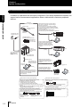
In addition to operations with the basic configuration, ZW series displacement sensors can
support various measurement applications when combined with numerous peripheral
devices.
ZW series
Basic configuration
Sensor head
Detects a target to
measure.
Photoelectric and
adjacent sensors
Measurement data can be easily loaded
into a PLC or personal computer through
Ethernet connections.
The Controller can be remotely controlled
from a personal computer; including switching
between or changing setting data and entering
measuring triggers.
(Communication with multiple devices
simultaneously cannot be achieved via Ethernet.)
ZW-S20
ZW-S40
PLC
Ethernet (note1)
Calibration ROM
(included with sensor head)
Associated with
the sensor on a
one-to-one basis
Controller
Performs
measurements
and outputs the
result.
The system receives
trigger signals to
control measuring
timings.
PC
Various Controller operations,
including, taking measured values
and judgment results, switching
between or changing setting data
or entering measuring triggers, are
available.
PLC
RS-232C cable
䇭䇭䇭䇭䇭䇭(note2)
ZW-C10T/C10AT
ZW-C15T/C15AT
Ethernet (note1)
Personal
computer
Smart Monitor ZW
(Exclusive personal
computer software)
PC
Displaying analog signals in
waveform from measured values
or judgment results in color is
available.
Analog output
Data loggers, etc.
ZW-SW_ _
Outputting measured values
or judgment results at a high
speed in parallel is available.
Allows making advanced settings and
checking up measured values easily using
exclusive personal computer software.
Accessory for the Controller
ZW-C10T/C15T.
ZW
User’s Manual
High-speed
input board
(Note1)㩷Ethernet cable (sold separately)
(Note2)㩷RS-232C cable (optional)
Prepare commercially available Ethernet cable
satisfying the following requirements:
- Category 5e or more, 30 m or less
- RJ45 connector (8-pin modular jack)
- For direct connection: Select cross cable.
- For connection through a network hub: Select straight
cable.
Depending on connecting devices, exclusive cables
may be supplied.
For PLC/programmable terminal: ZW-XPT2
For personal computer: ZW-XRS2
Extension fiber cable (optional)
(Note3)㩷Parallel cable (optional)
A exclusive extension fiber cable is available to
place the Sensor Head and Controller far apart than
the normal distance to each other.
Use the exclusive product for correct measurements.
A parallel cable for 52-pole extension connector
(ZW-XCP2) with 2 m cable is available.
Connecting adapter
(included with the fiber
cable for extension)
ZW-XFC
1-2
Parallel output (note3)
Extension fiber cable
ZW-XF_ _R
(2 m/5 m/10 m/20 m/30 m)
PC
Chapter 1
Part Names and Functions
Part Names and Functions
Sensor Head
㪌
㪋
㪉
㪊
Chapter 1 MEASUREMENT SETUP
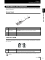
The following describes the names and functions of parts of the Sensor Head, Calibration
ROM and Controller.
㪈
No.
Names
Functions
1
Projector/receiver
Projects and receives light.
2
Serial number
Serial number.
Only a calibration ROM with the same serial number is available.
3
Fiber interface
Interfaces the Sensor Head and optical fiber (unremovable).
4
Fiber Cable
Sends or receives light signals to/from the Controller.
5
Fiber Connector
Couples the Controller and fiber cable.
Calibration ROM
This ROM is associated with the sensor on a one-to-one basis, and operates connected to
the Controller.
㪈
No.
1
Names
Serial number
Functions
Serial number.
Only a Sensor Head with the same serial number is available.
Use with the Calibration ROM always connected. If the Calibration ROM is not connected, an error is
displayed.
ZW
User’s Manual
1-3
Chapter 1
Part Names and Functions
Controller
Chapter 1 MEASUREMENT SETUP
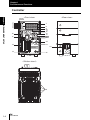
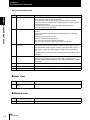
<Front view>
<Rear view>
Display
1
2
3
4
5
6
7
8
9
10
11
12
13
14
16
Control panel
17
15
20
21
18
Connectors/
terminals
19
23
22
䋼Bottom view䋾
24
1-4
ZW
User’s Manual
Chapter 1
Part Names and Functions
■ Front view
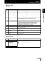
● Display
Names (light color)
Functions
1
HIGH indicator (orange)
The HIGH indicator is lit while judgment is resulted in HIGH (HIGH
threshold value measured value).
2
PASS indicator (green)
The PASS indicator is lit while judgment is resulted in PASS (LOW
threshold value measured value HIGH threshold value).
3
LOW indicator (orange)
The LOW indicator is lit while judgment is resulted in LOW (measured
value LOW threshold value).
4
STABILITY indicator
(green)
The STABILITY indicator is lit while a measured value is within the
measuring range.
It goes out if a measured value is out of the measuring range.
5
ZERO indicator (green)
The Zero Reset indicator is lit while the zero reset function is enabled.
6
ENABLE indicator (green) The ENABLE indicator lights when the Sensor is ready for measurement. It
goes off when measurement is not possible (e.g. when the received light
amount is excessive or insufficient, when the measuring range is
exceeded, when the calibration ROM is not connected, or when
measurement is not being performed in FUN mode).
7
Main display (red)
The main display shows measured values and/or function names.
8
Sub-display (green)
The sub-display shows additional information for measured values or
setting values for functions.
9
RUN indicator (green)
The RUN indicator is lit in the RUN mode, and goes out in the FUN mode.
10
THRESHOLD-L indicator
(orange)
The LOW threshold value indicator is lit when the Sub-display indicates a
LOW threshold value.
11
THRESHOLD-H indicator
(orange)
The HIGH threshold value indicator is lit when the Sub-display indicates a
HIGH threshold value.
Chapter 1 MEASUREMENT SETUP
No.
● Control panel
No.
Names
12
ZERORST/ESC key
13
(LEFT) key
(RIGHT) key
(UP) key
(DOWN) key
14
ZERO/SET key
15
Mode switching key
Functions
These keys function differently depending on operation modes.
Functions of Operating Keys p.2-3
ZW
User’s Manual
1-5
Chapter 1
Part Names and Functions
● Connectors/terminals
No.
Names
Functions
Chapter 1 MEASUREMENT SETUP
16
RS-232C connector
Connect the RS-232C cable when you are connecting the system with a
PLC or personal computer through RS-232C.
For the RS-232C cable, please use the following exclusive products:
If you use a cable not included in the exclusive products, a false operation
or breakdown may result.
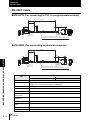
• For connecting to a PLC or programmable terminal: ZW-XPT2
• For connecting to a PC: ZW-XRS2
17
Ethernet connector
This connector is used to connect with a personal computer through
Ethernet.
Prepare commercially available Ethernet cable satisfying the following
requirements:
• Category 5e or more, 30 m or less
• RJ45 connector (8-pin modular jack)
• For one-to-one connection: Select cross cable.
• For connection through a network hub: Select straight cable.
18
52-pole expansion
connector
The 52-pole expansion connector is used to utilize extended functions,
such as binary I/Os, including output for measured value, GATE signal or
binary output task number outputs, or binary output object task selection
input signals; or bank I/O, including bank number output or bank select
input .
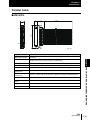
A parallel cable for 52-pole extension connector (ZW-XCP2) with 2 m cable
is available.
19
20-pole terminal block
The 20-pole terminal block connects the Controller DC24 V power supply
and basic I/Os, including output for analog voltage, analog current,
judgment, ALARM, BUSY or ENABLE, or input for ZERO, RESET, TIMING
or LED-OFF.
20
Fiber connector
The fiber connector connects the fiber cable.
21
ROM connector
The ROM connector connects the calibration ROM.
22
Frame ground terminal
This is the connector for frame ground. It connects grounding wire.
■ Rear view
No.
23
Names
DIN track attachment
hook
Functions
Used when fixing the controller on DIN track.
■ Bottom view
No.
24
1-6
Names
Installation hole
ZW
User’s Manual
Functions
Used when fixing the controller with screws.
Chapter 1
About Installation and Connection
About Installation and Connection
Chapter 1 MEASUREMENT SETUP
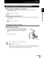
■ Checking the installation environment
Read “Precautions for safe use” at the beginning of this manual, and check the
installation environment.
Precautions for safe use p.6
■ Checking the installation site
Read “Precautions for correct use” at the beginning of this manual, and check the
installation site.
Precautions for correct use p.8
Installation of Sensor Head
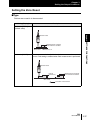
■ Installation procedure
Place the Sensor Head with an appropriate distance
from the target to measure, fixing it by tightening four
M3 screw inserted into their respective installation
holes.
Tightening torque: 0.54 Nm
M3 screw×4
• For the location screw holes, see the external dimensions.
External Dimensions p.6-3
• When measuring on a high-reflectivity workpiece, such as a mirror or wafer, false measured values
beyond the measuring range may be outputted. When a workpiece with diffuse reflection is used, we
recommend installing and adjusting while watching the position of the spot.
ZW
User’s Manual
1-7
Chapter 1
About Installation and Connection
Chapter 1 MEASUREMENT SETUP
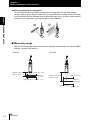
● Basic precautions for installation
Do not install the Sensor Head in a place where strong light hits the laser emitter/
receiver section of the Sensor Head. Also, if a workpiece has a shiny surface, the light
from the lighting will be reflected and a malfunction may occur. In such a case, prevent
reflection by, for example, covering the light to stop reflection.
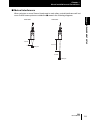
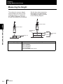
■ Measuring range
With the ZW series, the measurement center distance is expressed as 0 with the NEAR
side as + and the FAR side as -.
●ZW-S40
●ZW-S20
NEAR side㪑㩷㪂1 mm
Measurement center
distance㪑㩷20 mm
Measuring
center㪑㩷0 mm
Measuring range
FAR side㪑㩷㪄1 mm
Measurement center
distance㪑㩷40 mm
NEAR side㪑㩷㪂6 mm
Measuring
center㪑㩷0 mm
Measuring range FAR side㪑㩷㪄6 mm
1-8
ZW
User’s Manual
Chapter 1
About Installation and Connection
■ Mutual interference
When using two or more Sensor Heads next to each other, mutual interference will not
occur if other beam spots are outside the 䂓 areas in the following diagrams.
Chapter 1 MEASUREMENT SETUP
●ZW-S40
●ZW-S20
19 mm
2 mm
34 mm
300 μm
12 mm
800 μm
ZW
User’s Manual
1-9
Chapter 1
About Installation and Connection
Installation of Controller
Chapter 1 MEASUREMENT SETUP
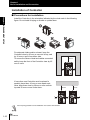
■ Precautions for installation
Install the Controller in the orientation indicated by the circle mark in the following
figure. Do not install it laying on its side or upside down.
For adequate intake and/or exhaust, keep the
Controller clear by 30 mm or more on its top, and
by 10 mm or more from either side.
To secure the Sensor Head and cables connected
safely, keep the front of the Controller clear by 65
mm or more.
30 mm
10
mm
If more than one Controller must be placed in
parallel, place them 10 mm or more apart each
other, keep them clear by 30 mm or more on their
top and 30 mm or more under them.
30 mm
10
mm
Do everything possible to avoid installation in a location with vibration.
1-10
ZW
User’s Manual
10
mm
10
mm
30 mm
10
mm
Chapter 1
About Installation and Connection
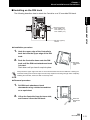
■ Installing on the DIN track
The following describes how to attach the Controller on a 35 mm-wide DIN track.
Chapter 1 MEASUREMENT SETUP
DIN track (option)
PFP-100N (1 m)
PFP-50N (0.5 m)
PFP-100N2 (1 m)
End plate (option)
PFP-M
● Installation procedure
1.
éÊÇËïtÇØï°ñ@
Hook the upper edge of the Controller's
back slot onto the upper edge of the DIN
track.
2.
Push the Controller down onto the DIN
track until the DIN track attachment hook
is locked.
DIN track
attachment
hook
Push down until you hear it snap into place.
Always hook the upper edge of the slot on the Controller's back first onto the DIN track. Hooking the
Controller starting from the lower edge of the slot may impair the mounting strength. After completely
installing the Controller, make sure that it is securely fixed.
● Removal procedure
1.
Pull DIN track attachment hook
downwards using a slotted screwdriver
or an equivalent.
2.
Lift up the Controller from the lower side,
and remove it from the DIN track.
DIN track
attachment
hook
ZW
User’s Manual
1-11
Chapter 1
About Installation and Connection
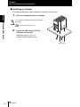
■ Installing on bottom
The following describes how to attach the Controller on its bottom.
Chapter 1 MEASUREMENT SETUP
1.
Drill four installation holes on the base.
For the location installation holes, see the external
dimensions.
External Dimensions p.6-11
2.
Tighten four M4 screws to fix the
Controller on the base.
Tightening torque: 1.2 Nm
Controller thread depth: 6 mm
M4 screw×4
1-12
ZW
User’s Manual
Chapter 1
About Installation and Connection
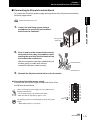
■ Connecting to 20-pole terminal block
To connect the Controller power supply and signal line to the 20-pole terminal block,
follow the steps below:
Chapter 1 MEASUREMENT SETUP
20-pole terminal block p.4-2
1.
Loosen the two fixing screws using a
screwdriver to remove 20-pole terminal
block from the Controller.
fixing screws
䋨both end䋩
2.
Push in and hold the release button next to
the terminal hole using a screwdriver while
pushing the wire fully into the terminal hole
and remove the screwdriver.
After the connection has been established, pull
the wire gently, to make sure that the
connection has been made securely.
Release button
Terminal hole
3.
Reinstall the 20-pole terminal block to the Controller.
● Connecting Controller power supply
Connects 24 VDC power supply to terminals 9 and 10 on
the 20-pole terminal block.
When connecting the power supply, be sure to adhere to the
following requirements:
• For the power supply, use AWG18 to 28 cables.
• Make the cable tip exposed by approx. 7 mm.
The following product is recommended for the 24 VDC power
0V
DC24 V
1
2
3
4
5
6
7
8
9
10
11
12
13
14
15
16
17
18
19
20
supply:
S8VS-06024 (Omron, 2.5 A, 60 W)
ZW
User’s Manual
1-13
Chapter 1
About Installation and Connection
Connecting Calibration ROM
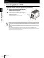
To connect the calibration ROM to the Controller, follow the steps below:
Chapter 1 MEASUREMENT SETUP
1.
Connect the calibration ROM to the ROM
connector on the Controller.
2.
Fix the calibration ROM by tightening the
supplied M2 screw.
M2 screw
Tightening torque: 0.15 Nm max.
Calibration ROM
ROM connector
• Before connecting or disconnecting the calibration ROM, make sure that the Controller's power supply
is turned OFF. The Controller may break down if the calibration ROM is connected while the power is
ON.
• Use with the Calibration ROM always connected. If the Calibration ROM is not connected, an error is
displayed.
• Only a calibration ROM and Sensor Head with a same serial number are compatible. When
connecting a calibration ROM with a Sensor Head, make sure that they have a same serial number, or
measurement cannot be performed correctly.
1-14
ZW
User’s Manual
Chapter 1
About Installation and Connection
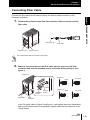
Connecting Fiber Cable
1.
Remove the protective caps from the controller's fiber connector and the
fiber cable.
Protective cap
Protective cap
Fiber cable
Chapter 1 MEASUREMENT SETUP
Connect the fiber cable on the Sensor Head to the Sensor Head connector on the
Controller as follows:
Fiber connector
Do not discard but keep the protective cap handy.
2.
Mate the convex section on the fiber cable with the groove on the fiber
connector and turn the threaded section clockwise while pushing in (see
figure 1).
(Figure 1)
(Figure 2)
Good
No good
Good
No good
Groove
(Figure 3)
Threaded
section
Fiber cable
Convex
section
Fiber
connector
In the "No good" status in figure 2 and figure 3, optic signals cannot be transmitted
and correct measurement is not possible. Always check that the system is in the
"Good" status.
ZW
User’s Manual
1-15
Chapter 1
About Installation and Connection
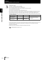
• Handling fiber cables
Use them in compliance with the following.
-Fiber cable bend radiuses must be at least 20 mm.
Chapter 1 MEASUREMENT SETUP
-Do not let bending cause stress at the root section of a fiber connector.
-Do not yank hard on a fiber cable.
-Do not step on a fiber cable or place anything heavy on it.
• Do not touch the end surface of a fiber cable, or the cable may be degraded in performance. Should
the end surface be touched or soiled, wipe the dirt away using a commercially available cleaner
exclusive for fiber connectors or dry and soft cloth. Do not use a cloth moistened with alcohol, or the
dirt may be reattached.
Point
Item
Model
Sensor Head side
Fiber connector
OPTIPOP R1
Controller side
Fiber connector
NEOCLEAN S250 ATC-ST-02N
ATC-RE-01
Manufacturer
NTT Advanced Technology
Corporation
• The fiber cable and fiber connectors should not be left with their protective caps removed, not even for
a short period of time. Leaving them unprotected can let dirt get on the end surface and cause
performance deterioration.
• Calibrate the Sensor Head after removing and inserting a fiber cable.
Calibrating Sensor Head p.1-19
1-16
ZW
User’s Manual
Chapter 1
About Installation and Connection
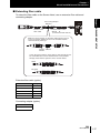
■ Extending fiber cable
To extend the fiber cable on the Sensor Head, use an extension fiber cable and
connecting adapter.
Chapter 1 MEASUREMENT SETUP
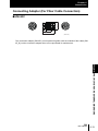
Connecting adapter
䇭ZW-XFC
Sensor Head
fiber cable
Extension fiber cable
㩷㩷ZW-XF_ _R䋺
㩷㩷䋨2 m/5 m/10 m/20 m/30 m䋩
Mate the convex section on the fiber cable with the groove
on the connection adapter and turn the threaded section
clockwise while pushing in.
Convex Groove
section
In the "No good" status in figure below, optic signals cannot
be transmitted and correct measurement is not possible.
Always check that the system is in the "Good" status.
Good
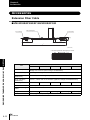
No good
Extension fiber cable (option)
Model
Length
ZW-XF02R
2m
ZW-XF05R
5m
ZW-XF10R
10 m
ZW-XF20R
20 m
ZW-XF30R
30 m
Connecting adapter (option)
Model
ZW-XFC
ZW
User’s Manual
1-17
Chapter 1
About Installation and Connection
• The connection adapter (ZW-XFC) comes packed together with the extension fiber cable
(ZW-XF_ _R).
• Never use any extension fiber cable and/or connecting adapter other than those specified in the
Chapter 1 MEASUREMENT SETUP
above.
• Hold the combined length of the normal and extension fiber cables to no more than 32 m.
• Only one fiber cable is allowed to extend the normal fiber cable. Never use two or more extension fiber
cable connected together.
• Do not touch the end surface of a fiber cable, or the cable may be degraded in performance. Should
the end surface be touched or soiled, wipe the dirt away using a commercially available cleaner
exclusive for fiber connectors or dry and soft cloth. Do not use a cloth moistened with alcohol, or the
dirt may be reattached.
Point
Item
Model
Sensor Head side
Fiber connector
OPTIPOP R1
Controller side
Fiber connector
NEOCLEAN S250 ATC-ST-02N
ATC-RE-01
Manufacturer
NTT Advanced Technology
Corporation
• The fiber cable and fiber connectors should not be left with their protective caps removed, not even for
a short period of time. Leaving them unprotected can let dirt get on the end surface and cause
performance deterioration.
• Calibrate the Sensor Head after removing and inserting an optical fiber.
Calibrating Sensor Head p.1-19
1-18
ZW
User’s Manual
Chapter 1
About Installation and Connection
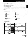
Calibrating Sensor Head
mirror. )
䊶Without any workpiece
within the measuring range
䊶With light shielded
Chapter 1 MEASUREMENT SETUP
Calibrate the Sensor Head by obtaining the dark data in the no-incoming light status.
• When using the sensor for the first time.
• When removing and inserting a fiber cable from/to the Controller.
• When extending a fiber cable.
The Sensor Head should be calibrated without any workpiece within the measuring range
or with the tip of the Sensor Head shielded from light with an object with diffuse reflection.
(Correct calibration is not possible with a transparent object, semi-transparent object, or
Sensor head
Sensor head
Install an object with diffuse
reflection (metal, paper, plastic, etc.)
than the measurement range.
Measuring range
Measuring range
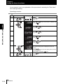
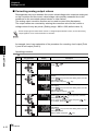
Operating procedure
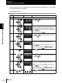
Steps
1
Key operation
Display
RUN
FUN
LTEACH
H
L
Description
UNLIT
Press
RUN
mode.
RUN
key for two seconds to enter the FUN
FUN
LTEACH
(For details on the functions of the
RUN
key, see
FUN
LTEACH
p.2-3.)
2
ZERORST/ ESC
Press
or
and press
keys to select either of "SYSTEM"
key.
Press
or
and press
keys to select either of "H.CALIB"
key.
ZERO/ SET
3
ZERO/ SET
ZERO/ SET
4
ZERORST/ ESC
"OK/CAN" appears on the sub-display.
To execute press
key, or the
cancel.
ZERORST/ ESC
ZERO/ SET
key to
ZERO/ SET
ZW
User’s Manual
1-19
Chapter 1
About Installation and Connection
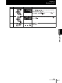
Steps
5
Key operation
FUN
LTEACH
Chapter 1 MEASUREMENT SETUP
1-20
Display
RUN
H
L
Description
LIT
Press
RUN
mode.
RUN
FUN
key for two seconds to enter the RUN
LTEACH
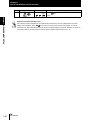
When Sensor Head calibration fails
If the Sensor Head is calibrated in an inappropriate environment, an error is displayed on the main
display. If this happens, press
ZERORST/ ESC
key to return to the previous screen and try again. If an error
continues even after calibrating the Sensor Head in an appropriate environment, the fiber connector on
the Sensor Head or controller may be stained. Clean the fiber cable referring to p.1-16.
ZW
User’s Manual
Chapter 1
Smart Monitor ZW
Smart Monitor ZW
Smart Monitor ZW
ZW-SW_ _
(Accessory for the Controller
ZW-C10AT/C15AT.)
Ethernet cable
Chapter 1 MEASUREMENT SETUP
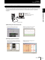
ZW series is provided with the Smart Monitor ZW software utility. This utility allows you to set
up sensing functions and monitor the waveforms of measurement results on a personal
computer.
● Monitoring the measurement state
Checks the measured value of the
gang-mounted controller in the list.
Displays the change of the time series
for the measured value in a graph.
● Setting support for functions
Sets the sensing conditions in detail while
checking the receiving status of the Sensor
Head (sensitivity).
Displays and sets the settings for the
controller in the list.
ZW
User’s Manual
1-21
Chapter 1
Smart Monitor ZW
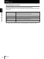
Operating Environment
Chapter 1 MEASUREMENT SETUP
The following describes the operating environment for Smart Monitor ZW.
Before starting installation on a personal computer, make sure that it satisfies the following
requirements:
Item
Condition
OS
Windows 7 (32 or 64-bit version)
Windows XP (Service Pack3 or more, 32-bit version)
CPU
Intel Pentium III, 850 MHz or more (2 GHz or more is recommended.)
Memory
1 GB or more
Free hard disk space
50 MB or more
Display
1024 x 768 dots or more, 16 million colors or more
Supported languages
Japanese/English
Communication port
Ethernet port
• Windows is a trademark or registered trademark of Microsoft Corporation.
• The system and product names are trademarks or registered trademarks of their respective companies.
1-22
ZW
User’s Manual
Chapter 1
Smart Monitor ZW
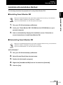
Installation/Uninstallation Method
The following describes the preparations for using Smart Monitor ZW.
• Before you install Smart Monitor ZW, quit all other programs that are running. If virus detection
software is enabled, installation may take time to complete.
• Log on as an Administrator or a user with system access rights.
1.
2.
Turn your PC ON and startup up Windows.
Insert your "Smart Monitor ZW" CD-ROM into the CD-DOM drive on your
personal computer.
3.
Chapter 1 MEASUREMENT SETUP
■ Installing Smart Monitor ZW
Auto-run automatically displays the installation screen. Follow the onscreen instructions to install Smart Monitor ZW.
■ Uninstalling Smart Monitor ZW
• Before you uninstall Smart Monitor ZW, quit all other programs that are running. If virus detection
software is enabled, uninstallation may take time to complete.
• Log on as an Administrator or a user with system access rights.
● For Windows 7
1.
2.
3.
4.
5.
Turn your PC ON and startup up Windows.
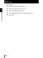
Select [Control Panel] from the start menu.
Double-click [Uninstall a program].
Right-click [SmartMonitorZW] from the list and select [Uninstall].
Click the [Yes].
ZW
User’s Manual
1-23
Chapter 1
Smart Monitor ZW
● For Windows XP
Chapter 1 MEASUREMENT SETUP
1.
2.
3.
4.
5.
1-24
ZW
User’s Manual
Turn your PC ON and startup up Windows.
Select [Control Panel] from the start menu.
Double-click [Add/Remove Programs].
Select [SmartMonitorZW] from the list and click the [Remove].
Click the [Yes].
Chapter 1
Smart Monitor ZW
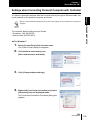
Settings when Connecting Personal Computer with Controller
Specify a network address appropriate for the Controller settings as the IP address for the personal
computer.
The controller default settings are as follows:
• IP address: 192 168.250.50
• Subnet mask: 255.255.255.0
● For Windows 7
1.
Chapter 1 MEASUREMENT SETUP
To connect a personal computer with the Controller directly through an Ethernet cable, set
up the network on the personal computer as follows:
Select [Control Panel] from the start menu.
The [Control Panel] dialog box appears.
2.
Click [Network and Internet], and
[View network status and tasks].
3.
Click [Change adapter settings].
4.
Right-click [Local Area Connection] and select
[Properties] from the displayed menu.
The [Local Area Connection Properties] dialog box
appears.
ZW
User’s Manual
1-25
Chapter 1
Smart Monitor ZW
5.
Under the [Network] tab, doubleclick [Internet Protocol Version 4
Chapter 1 MEASUREMENT SETUP
(TCP/IPv4)].
The [Internet Protocol Version 4 (TCP/
IPv4) Properties] dialog box appears.
6.
Click the [Use the following IP
address] option and enter an IP
address and subnet mask.
Example:
When matching the computer
settings to the controller's network
address and setting the following
values:
IP address: 192.168.250.2
Subnet mask: 255.255.255.0
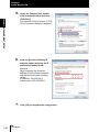
7.
1-26
ZW
User’s Manual
Click [OK] to complete the configuration.
Chapter 1
Smart Monitor ZW
● For Windows XP
1.
Select [Control Panel] from the start menu.
2.
Chapter 1 MEASUREMENT SETUP
The [Control Panel] dialog box appears.
Click [Network and Internet
Connection], and [Network
Connections].
The [Network Connections] dialog box
appears.
3.
Right-click [Local Area Connection] and select
[Properties] from the displayed menu.
The [Local Area Connection Properties] dialog box
appears.
4.
Under the [General] tab, double-click
[Internet Protocol (TCP/IP)].
The [Internet Protocol (TCP/IP) Properties]
dialog box appears.
ZW
User’s Manual
1-27
Chapter 1
Smart Monitor ZW
5.
Click the [Use the following IP address]
option and enter an IP address and
Chapter 1 MEASUREMENT SETUP
subnet mask.
Example:
When matching the computer settings to
the controller's network address and
setting the following values:
IP address: 192.168.250.2
Subnet mask: 255.255.255.0
6.
1-28
ZW
User’s Manual
Click [OK] to complete the configuration.
Chapter 1
Smart Monitor ZW
Starting and Exiting
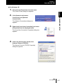
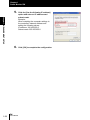
After installation is completed, start up Smart Monitor ZW by the following procedure.
1.
2.
3.
Make sure that the Controller is connected to the personal computer.
Turn the Controller ON and set it to the RUN mode.
Select [Programs]-[OMRON]-[ZW]-[SmartMonitorZW] from the Windows
[Start] menu.
■ Exiting Smart Monitor ZW
1.
Select [File]-[Close] in the Smart Monitor ZW menu bar.
ZW
User’s Manual
Chapter 1 MEASUREMENT SETUP
■ Start-up of Smart Monitor ZW
1-29
Chapter 1
Smart Monitor ZW
Chapter 1 MEASUREMENT SETUP
1-30
ZW
User’s Manual
Chapter 2
BASIC OPERATION
2-2
Operation Modes
2-2
Functions of Operating Keys
2-3
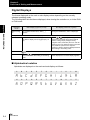
Digital Displays
2-4
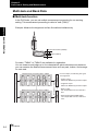
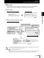
Multi-task and Bank Data
2-6
Setting Flow
Functions and Operations during Measurement
Chapter 2 BASIC OPERATION
Overview of Setting and Measurement
2-8
2-10
Switching the Display during RUN mode
2-10
Zero Reset
2-14
Setting Threshold Value
2-17
Bank Switching
2-20
ZW
User’s Manual
2-1
Chapter 2
About Installation and Connection/Sensor Head
Overview of Setting and Measurement
Operation Modes
Chapter 2 BASIC OPERATION
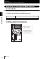
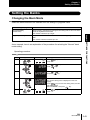
The controller has the following three operating modes.
Switch to the desired mode before you start operation.
(The controller starts up in the RUN mode whenever turning it on.)
Mode
Description
RUN Mode
Normal operating mode.
FUN Mode
Mode for setting the measurement conditions.
RUN
Use
key to switch between the operating modes.
The RUN indicator identifies the current operating mode.
FUN
LTEACH
RUN mode: Turned on.
FUN mode: Turned off.
To switch between the RUN
and FUN modes, press and hold
the button for two seconds.
2-2
ZW
User’s Manual
Chapter 2
Overview of Setting and Measurement
Functions of Operating Keys
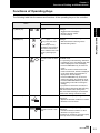
The following table lists the names and functions of the operating keys on the controller:
Functions
Name
RUN mode
FUN mode
Changes sub-display
content.
Functions differently depending on the
settings.
- Toggles functional displays.
- Selects a digit for values.
- Cancels settings.
(UP) key
(DOWN) key
key: Executes trigger
input.
key: Executes reset
input.
* These keys are only
available if key inputs for
the hold functions have
been enabled in the FUN
mode. (See Page p.334).
Functions differently depending on the
settings.
- Switches between selecting menus.
- Selects setting values.
Hold down for at least two
seconds to enter the FUN
mode.
Hold down for at least two seconds to enter
the RUN mode.
- For operating mode switching, "SWITCH"
is displayed on the main display and "OK/
CAN" is displayed on the sub-display.
Press the ZERO/SET key to switch the
mode.
- When the mode is switched from FUN
mode to RUN mode, "SAVE" is displayed
on the main display and "OK/CAN" is
displayed on the sub-display.
Press the ZERO/SET key to save the
settings and switch the operating mode.
Press the ZERORST/ESC key to switch
the operating mode without saving the
settings.
If you press for less than 2 seconds, the
display shifts to RUN mode task switching
and the threshold value setting menu.
Also, this starts teaching to set threshold
values when setting a threshold value.
Executes a zero reset.
Functions differently depending on the
selections.
- Applies the selected conditions or values.
- Switches to a lower menu.
Hold down for at least two
seconds to cancel a zero
reset.
Functions differently depending on the
selections.
- Cancels a selected condition or value.
- Switches to an upper menu.
Hold down for at least two seconds to jump
to the top menu on the FUN mode.
Mode switching key
RUN
FUN
LTEACH
ZERO/SET key
ZERO/ SET
ZERORST/ESC key
ZERORST/ ESC
ZW
User’s Manual
Chapter 2 BASIC OPERATION
(LEFT) key
(RIGHT) key
2-3
Chapter 2
Overview of Setting and Measurement
Digital Displays
The theme displayed on the main or sub-display varies depending on the currently
selected operating mode.
The following table lists the theme displayed, when turning the controller on, or in the RUN
or FUN mode.
Chapter 2 BASIC OPERATION
Operating
mode
Main display (upper line, in red)
When turning
on
The controller model name, "ZW-C_ _"
appears.
Sub-display (lower line, in green)
During the initialization, "INIT" is displayed.
The system enters the RUN mode after displaying "INIT" for a few seconds.
RUN mode
The task measurement result appears.
The task to display can be toggled (see p.212).
Press and hold
RUN
FUN
Press
/
key to cycle through the
sequence of the HIGH and LOW threshold
values, analog output (voltage/current),
judgment result, resolution (the max. and min.
values for one-min measured value), exposure
time, distance (sensor to the object to
measure), effective bank and displayed task in
descending or ascending order.
key for two seconds or more to switch between the RUN and FUN modes.
LTEACH
FUN mode
Press
/
keys to cycle through the
function names in descending or ascending
order.
When reaching the lowest layer, the setting
value displayed on the main display appears.
■ Alphabetical notation
Alphabets are displayed on the main and sub-display as follows:
A
B
C
D
E
F
G
H
I
J
K
L
M
# $ % & ' ( ) * + , . /
N
O
P
Q
R
S
T
U
V
W
X
Y
Z
0 2 3 4 5 6 7 8 9 : ; <
2-4
ZW
User’s Manual
Chapter 2
Overview of Setting and Measurement
■ Entering numerical values
To enter numerical values, including parameters, for the sub-display, follow the steps
below:
Sub-display
(Parameter)
ZERO/ SET
Select
value
(1) When entering numerical values, the sub-display displays the current setting value
and its uppermost digit flashes.
(2) Press the
/
keys to select a digit to enter a number.
Press the
key on the rightmost digit moves blinking to the leftmost digit.
Press the
key on the leftmost digit moves blinking to the rightmost digit.
(3) Press the
/
(4) Press the
ZERO/ SET
keys to select a number to enter.
Chapter 2 BASIC OPERATION
Select
digit
Apply
key to apply the entered value.
● Positioning decimal point
To position a decimal point, follow the steps below:
Sub-display
(Parameter)
ZERO/ SET
Apply
Select
position
(1) If a decimal point has been defined, it flashes on the sub-display.
(2) Press the
/
keys to position the decimal point.
Position the decimal point at the rightmost digit to erase it.
Press the
key on the rightmost digit moves blinking to the leftmost digit.
Press the
key on the leftmost digit moves blinking to the rightmost digit.
(3) Press the
ZERO/ SET
key to apply the position of the decimal point.
ZW
User’s Manual
2-5
Chapter 2
Overview of Setting and Measurement
Multi-task and Bank Data
■ Multi-task function
In the ZW Series, you can set multiple measurement processing for one sensing
setting. This measurement processing is called a "task (TASK)."
Chapter 2 BASIC OPERATION
Example: Measure the height and surface fluctuation simultaneously
Surface fluctuation (TASK2)
Height (TASK1)
For tasks, "TASK1" to "TASK4" are available for registration.
You can measure and judge up to four characteristic points simultaneously because
you can measure the desired measurement items such as peak, bottom, and average
for each task.
* For the output, the following four types
are supported:
2-6
ZW
User’s Manual
Output *
Measurement result
Judge
Zero reset
Hold
Scaling
Filter
䇭㪄Analog output
䇭䇭Select one TASK that you want to output.
䇭㪄Judgment output
䇭䇭Select one TASK that you want to output.
䇭䇭
䇭㪄Binary output
䇭 Can output data from four tasks at a
time.
Output *
Judge
Zero reset
Hold
Scaling
Filter
Measurement item
Measurement processing flow in TASK4
Measurement item
Sensing setting
Measurement processing flow in TASK1
䇭㪄Serial output (Ethernet/RS-232C)
䇭䇭Can output data from four tasks at a
time.
Chapter 2
Overview of Setting and Measurement
■ Bank data
ZW series can hold up to eight sets of settings, which are called a "bank (BANK)".
When the device setup is changed, you can switch the bank externally.
● What is bank?
The sensing settings for measurement
Filter
Output
I/O
Threshold value
Sensing
Filter
Output
I/O
Chapter 2 BASIC OPERATION
Sensing
are held as one bank.
Threshold value
BANK
● Example of bank switching for settings
If you register settings of various classes,
Register the different settings
for changing the device setup.
Sensing setting for product class A
Sensing
Filter
䉶䊮䉲䊮䉫
᷹ቯὐ
䊐䉞䊦䉺
Output
I/O
Threshold value
䉶䊮䉲䊮䉫
᷹ቯὐ
䊐䉞䊦䉺
ജ
I/O⸳ቯ
䈚䈐䈇୯
ജ
I/O⸳ቯ
䈚䈐䈇୯
䉶䊮䉲䊮䉫
᷹ቯὐ BANK1
䊐䉞䊦䉺
Measuring operation
BANK2
with the contents set
䈚䈐䈇୯
BANK3
in BANK1
䊶
䊶
䊶
BANK8
Switch
to BANK2.
Measuring operation
with the contents set in
BANK2
Sensing
setting᷹ቯὐ
for product䊐䉞䊦䉺
class B
䉶䊮䉲䊮䉫
Sensing
Filter
ജ
I/O⸳ቯ
䈚䈐䈇୯
䉶䊮䉲䊮䉫
᷹ቯὐ
䊐䉞䊦䉺
Output
I/O
Threshold value
ജ
I/O⸳ቯ
䈚䈐䈇୯
䉶䊮䉲䊮䉫
᷹ቯὐ BANK1
䊐䉞䊦䉺
BANK2
䈚䈐䈇୯
䊶 BANK3
䊶
䊶
BANK8
It is easy to change the device setup.
Sensing
TASK4
Filter
Measurement point
Output
Threshold value
䊶䊶
䊶
TASK1
Measurement point
Filter
Output
Threshold value
TASK1 to TASK4 are
specified in the settings
for each bank.
I/O
BANK1
• If only the "threshold value" is different in the settings for a bank, by changing the mode of the bank,
you can increase the number of banks from 4 to 32.
Changing the Bank Mode p.3-43
• The output destination (current output value/voltage output value) in the I/O setting parameters is set
the same for all banks. The output destination cannot be set separately for individual banks.
ZW
User’s Manual
2-7
Chapter 2
Setting Flow
Setting measurement items
Saving the Settings
Setting for output processing
Chapter 2 BASIC OPERATION
Preparation for measurement
Setting Flow
2-8
Chapter 1 MEASUREMENT SETUP About Installation and Connection
Installation & Connection
Attach a Sensor Head.
Power ON
Default setting when connect
sensor head
Calibrate the Sensor Head.
Setting measurement items
Select task(s) from TASK1 to TASK4, and set up measurement
items, including height, thickness and calculation.
Setting the Scaling
Correct the display of the measured value.
Setting HOLD
Set the hold conditions.
Setting the Zero Reset
Set zero reset.
Save the Settings Data
Save the data you have set.
ZW
User’s Manual
Chapter 1 MEASUREMENT SETUP Calibrating Sensor Head
Chapter 3 SETTINGS FOR FUNCTIONS
- Setting Measurement Items
Chapter 3 SETTINGS FOR FUNCTIONS
- Setting the Scaling
Chapter 3 SETTINGS FOR FUNCTIONS
- Setting the Hold
Chapter 3 SETTINGS FOR FUNCTIONS
- Zero Reset
Chapter 3 SETTINGS FOR FUNCTIONS
- Saving the Bank/System Settings
Make sure that you always save the data after you set it.
If you turn OFF the power without saving the data, all the settings data will be cleared.
Operations and Settings as
Required
If You Cannot Perform a
Measurement Smoothly
Threshold Setting
Chapter 2 BASIC OPERATION Setting Threshold Value
Bank Switching
Chapter 2 BASIC OPERATION Bank Switching
Executing Zero Reset
Chapter 2 BASIC OPERATION Zero Reset
I/O Setting
(Analog, Judgement, and Binary output)
Chapter 4 I/O SETTINGS
Using Ethernet/RS-232C
Communications
Chapter 5 Ethernet/RS-232C
COMMUNICATION
Setting Banks
Chapter 3 SETTINGS FOR FUNCTIONS
- Changing the Bank Mode
Setting the System Environment
Chapter 3 SETTINGS FOR FUNCTIONS
- Setting the System
Changing Material Settings
Chapter 3 SETTINGS FOR FUNCTIONS
- Setting the Material for the Target to Measure
Changing Exposure Time Control
Mode Settings
Chapter 3 SETTINGS FOR FUNCTIONS
- Setting Exposure Time Control Mode
Setting Filter
Chapter 3 SETTINGS FOR FUNCTIONS
- Setting the Filter
Chapter 2 BASIC OPERATION
Functions Used During
Operation
Chapter 2
Setting Flow
When a problem occurs...
When The Smart Sensor Does
Not Operate Correctly
Chapter 7 APPENDIX - Troubleshooting
When An Error Message Appears
Chapter 7 APPENDIX - Error Messages
and Countermeasures
ZW
User’s Manual
2-9
Chapter 2
Functions and Operations during Measurement
Functions and Operations during Measurement
Switching the Display during RUN mode
Chapter 2 BASIC OPERATION
In RUN mode, you can switch measured value display by pressing the
/
keys
during the operation.
You can check the threshold value and analog output value while displaying the measured
value on the main display.
HIGH threshold
value
H lit
L unlit
Displayed
task
LOW threshold
value
H unlit
L lit
Effective
bank
Analog voltage
output value
H unlit
L unlit
Distance
Analog current
output value
H unlit
L unlit
Exposure
time
(Note)
Judgement
result
H unlit
L unlit
Resolution
Effective
bank
H unlit
L unlit
H unlit
L unlit
H unlit
L unlit
• "Displayed task" can be selected from TASK1 to TASK4.
• The above display screenshots are only samples and may different from actual displays.
(Note)
An output item not selected on the analog output (Voltage output/Current output) is displayed as "------" on the
sub-display. For example, if "Voltage output" is selected on the analog output, the analog current output value is
displayed as "------" on the sub-display.
■ Details displayed on the main display
The measured values always appear on the main display.
The measured values are initialized as follows:
• Reference value 0: measurement center distance
• + display: NEAR (close range) side
• - display: FAR (far range) side
2-10
ZW
User’s Manual
Chapter 2
Functions and Operations during Measurement
■ Details displayed on the sub-display
The items listed in the following table appears on the sub-display.
Press the
/
keys to toggle the display.
Display Details
Description
Displays the HIGH and LOW threshold values.
When displaying a HIGH threshold value, the THRESHOLD-H indicator lights up,
while for a LOW threshold value, the THRESHOLD-L indicator lights up.
Analog output
Displays the voltage or current value output in analog format.
The display details for the output destination setting are different for voltage output
and for current output. (Values displayed here are reference values only. These
values differ from actual analog output values.)
Judgment result
The judgment result for each task appears.
The TASK1, 2, 3 and 4 judgment results are displayed starting from the left.
H: HIGH
P: PASS
L: LOW
E: ERROR
Resolution
Displays the fluctuation width (peak to peak) of the measured value over a fixed
amount of time.
Exposure time
Displays the current exposure time.
It ranges from 1 to 5000 s.
Distance
Displays the distance from the sensor to a target to measure.
Effective bank
Displays the current bank number.
Displayed task
Displays the currently selected task number, from TASK1 to TASK4.
The measured value for the selected task appears on the main display.
ZW
User’s Manual
Chapter 2 BASIC OPERATION
Threshold
2-11
Chapter 2
Functions and Operations during Measurement
■ Display details change
The measurement result displayed on the main display in RUN mode can be selected
from TASK 1 to 4.
The number of digits displayed can also be changed.
Settings [Display]
Description [Display]
Chapter 2 BASIC OPERATION
Task for displayed target
[DISP]
TASK1/TASK2/TASK3/TASK4
Decimal point digit
[DEC.NUM]
0 [0DIG]/1 [1DIG]/2 [2DIG]/3 [3DIG]/4 [4DIG]/5 [5DIG]
As an example, here is an explanation of the procedure for setting TASK2 as the task
to be displayed target.
Operating procedure
Steps
1
Key operation
RUN
Description
LIT
FUN
LTEACH
2
Display
H
L
RUN
Press
key in the RUN mode to display the
FUN
LTEACH
setting menu.
Press
press
ZERORST/ ESC
RUN
ZERO/ SET
or
key.
keys to select either of "DISP" and
ZERO/ SET
3
Select the task to be displayed target.
The current setting value is displayed on the subdisplay.
Press
/
key to enter the editing mode, and the
sub-display blinks.
Select either of "TASK2" and press
key.
ZERORST/ ESC
ZERO/ SET
ZERO/ SET
4
ZERORST/ ESC
LIT
H
2-12
ZW
User’s Manual
L
RUN
Press
menu.
ZERORST/ ESC
key in the RUN mode to exit the setting
Chapter 2
Functions and Operations during Measurement
■ Threshold values change
The threshold value for the task displayed on the main display in RUN mode can be
changed.
To change the target task, change the task displayed on the main display.
Display details change p.2-12
Operating procedure
Steps
1
Key operation
Description
LIT
FUN
LTEACH
2
Display
RUN
H
L
RUN
Press
RUN
key in the RUN mode to display the
FUN
LTEACH
setting menu.
Press
or
and press
ZERORST/ ESC
ZERO/ SET
Chapter 2 BASIC OPERATION
As an example, here is an explanation of the procedure for setting the HIGH threshold
value by entering "1.000" directly.
keys to select either of "H.JUDGE"
key.
ZERO/ SET
3
ZERORST/ ESC
ZERO/ SET
LIT
H
L
RUN
Set "1.000" as the HIGH threshold value.
The current measured value is displayed on the main
display and the current set threshold value is
displayed on the sub-display. (At that time, the
THRESHOLD-H indicator lights up.)
Press
key to enter the editing mode, and the
sub-display blinks.
To edit numerical values use
/ /
/
keys.
Enter "1.000" and press
key.
ZERO/ SET
ZERO/ SET
4
ZERORST/ ESC
LIT
H
L
RUN
Press
menu.
ZERORST/ ESC
key in the RUN mode to exit the setting
ZW
User’s Manual
2-13
Chapter 2
Functions and Operations during Measurement
Zero Reset
■ What is zero reset?
Chapter 2 BASIC OPERATION
This function allows resetting the measured value to "0" at any timing during
measurement in the RUN mode.
The measured value can be displayed and output as a positive or negative deviation
(tolerance) from the set reference value "0".
Example 1:Using the height of sensing object registered as the reference value and the
tolerance output as the measured value
Sensor head
+2 (HIGH threshold value)
0
(reference value)
㪪㪼㫅㫊㫀㫅㪾
㫆㪹㫁㪼㪺㫋
-2 (LOW threshold value)
Example 2:Using the height of sensing object as the measured value with an offset set
to 10
Sensor head
+12 (HIGH threshold value)
10
㪪㪼㫅㫊㫀㫅㪾
㫆㪹㫁㪼㪺㫋
2-14
ZW
User’s Manual
+8 (LOW threshold value)
Chapter 2
Functions and Operations during Measurement
Example 3:Using zero reset to measure steps in sensing object (zero reset at each
measurement
Sensor head
Zero reset
executed
Zero reset
executed
Zero reset
executed
Direction of movement
The zero reset function also allows setting the reference value to the hold value for a
hold measurement or any value other than zero.
Chapter 2 BASIC OPERATION
This step is
measured.
Setting the Zero Reset p.3-37
■ Executing zero reset
1.
Place the reference sensing object in position.
ZW
User’s Manual
2-15
Chapter 2
Functions and Operations during Measurement
2.
Press
ZERO/ SET
key.
The ZERO indicator illuminates and the current
measured value is registered as 0 (zero).
Chapter 2 BASIC OPERATION
• When a zero reset is executed, the analog output becomes the voltage or current value at the center of
the two preset points. Analog output becomes roughly 0 V or 12 mA when focus is not set.
Setting focus p.4-14
• The Zero Reset function can also be executed by supplying a ZERO signal to the 20-pole terminal
block.
20-pole terminal block p.4-2
ZERO input p.4-8
■ Canceling zero reset
1.
Press and hold
ZERORST/ ESC
key for two seconds.
The zero reset function can also be canceled by supplying a ZERO signal to the 20-pole terminal block.
20-pole terminal block p.4-2
ZERO input p.4-8
2-16
ZW
User’s Manual
Chapter 2
Functions and Operations during Measurement
Setting Threshold Value
Switch the controller to the FUN mode and set the range in order for the measured value
to be judged as PASS.
Both HIGH and LOW threshold values are set.
As a judgment result, HIGH, PASS or LOW is output.
Chapter 2 BASIC OPERATION
HIGH threshold value
Measured value
LOW threshold value
Output
HIGH
ON
OFF
PASS
ON
OFF
LOW
ON
OFF
ON when Measurement result
> HIGH threshold value
ON when LOW threshold value
< Measurement result
< HIGH threshold value
ON when Measurement result
<LOW threshold value
A judgment result appears on the controller as follows:
• For judgment result HIGH: The HIGH indicator lights up.
• For judgment result PASS: The PASS indicator lights up.
• For judgment result LOW: The LOW indicator lights up.
There are two ways of setting the threshold value.
Method
Teaching
Operating key
RUN
FUN
LTEACH
Direct
Details
Performs measurement and uses the measurement results to set threshold
values.
Position teaching is useful when threshold samples, i.e., with the upper and
lower limits, can be obtained beforehand.
/
/
/
The threshold values can be set by directly inputting numerical values.
Direct input is useful when you know the dimensions for an OK judgment or
when you want to fine-tune threshold values after teaching.
• Hysteresis (hysteresis width) can also be set to threshold values. Set hysteresis when measured values are dispersed around a threshold value, and judgments are unstable, to prevent chattering.
Settings for Judgment Output p.4-18
• Threshold values can also be adjusted by directly entering values in the RUN mode. This helps you to
make fine adjustments without shutting down the system.
Threshold values change p.2-13
ZW
User’s Manual
2-17
Chapter 2
Functions and Operations during Measurement
■ Teaching
Performs measurement and uses the measurement results to set threshold values.
Sensor head
Sensor head
Chapter 2 BASIC OPERATION
Teaching point
= HIGH threshold value
Teaching point
= LOW threshold value
Threshold sample
(upper limit)
Threshold sample
(lower limit)
Hold, trigger, and scaling settings that have been made before teaching are reflected in
the teaching measurements.
As an example, here is an explanation of the procedure for setting the current
measured value as a HIGH threshold value.
Operating procedure
Steps
1
Key operation
RUN
FUN
LTEACH
2
3
Display
ZERORST/ ESC
ZERO/ SET
H
L
Description
UNLIT
Press
RUN
mode.
RUN
key for two seconds to enter the FUN
FUN
LTEACH
Press
press
ZERO/ SET
or
keys to select either of "MEAS" and
key.
Press
or
and press
keys to select either of "TASK1"
key.
Press
or
and press
keys to select either of "JUDGE"
key.
Press
or
and press
keys to select either of "TEACH"
key.
ZERO/ SET
4
ZERO/ SET
5
ZERO/ SET
6
Select "HIGH threshold value" as the threshold value
type.
Press
or
keys to select either of "H.JUDGE"
and press
key.
ZERO/ SET
2-18
ZW
User’s Manual
Chapter 2
Functions and Operations during Measurement
Steps
Key operation
7
Display
Description
The current measured value is displayed on the main
display and the current set threshold value is
displayed on the sub-display. (At that time, the
THRESHOLD-H indicator lights up.)
Press
key to display the current measured
RUN
FUN
LTEACH
RUN
LIT
H
FUN
LTEACH
L
-
Press
key to start a teaching.
The indicator for the current measured value on the
main display lights up, applying the value as a
threshold value.
ZERO/ SET
ZERO/ SET
9
LIT
Press
RUN
mode.
RUN
FUN
LTEACH
H
L
value on the lower line.
RUN
key for two seconds to enter the RUN
FUN
LTEACH
■ Direct
The threshold values can be set by directly inputting numerical values.
Chapter 2 BASIC OPERATION
8
RUN
As an example, here is an explanation of the procedure for setting a HIGH threshold
value by entering "40.000" directly.
Operating procedure
Steps
1-4
5
Key operation
Display
Description
For moving to “JUDGE” see steps 1 to 4 in p.2-18
Press
or
and press
ZERORST/ ESC
ZERO/ SET
6
keys to select either of "DIRECT"
key.
Select "HIGH threshold value" as the threshold value
type.
Press
or
keys to select either of "H.JUDGE"
and press
key.
ZERO/ SET
ZERO/ SET
7
ZERORST/ ESC
ZERO/ SET
LIT
H
L
RUN
Set "40.00" as the HIGH threshold value.
The current measured value is displayed on the main
display and the current set threshold value is
displayed on the sub-display. (At that time, the
THRESHOLD-H indicator lights up.)
Press
key to enter the editing mode, and the
sub-display blinks.
To edit numerical values use
/ /
/
keys.
Enter "40.00" and press
key.
ZERO/ SET
ZERO/ SET
8
RUN
FUN
LTEACH
H
L
LIT
Press
RUN
mode.
RUN
FUN
key for two seconds to enter the RUN
LTEACH
ZW
User’s Manual
2-19
Chapter 2
Functions and Operations during Measurement
Bank Switching
Switches banks.
As an example, here is an explanation of the procedure for setting BANK2:
Chapter 2 BASIC OPERATION
Operating procedure
Steps
1
Key operation
Display
RUN
FUN
H
LTEACH
2
L
Description
UNLIT
Press
RUN
mode.
3
key for two seconds to enter the FUN
FUN
LTEACH
Press
press
ZERORST/ ESC
RUN
ZERO/ SET
or
key.
Press
or
and press
ZERO/ SET
ZERO/ SET
4
keys to select either of "BANK" and
keys to select either of "BK.CHG"
key.
Select BANK2 for the bank number.
The current setting value is displayed on the subdisplay.
Press
/
keys to enter the editing mode, and the
sub-display blinks.
Select "BANK2" and press
key.
ZERORST/ ESC
ZERO/ SET
ZERO/ SET
5
RUN
FUN
LTEACH
H
L
LIT
Press
RUN
mode.
RUN
FUN
key for two seconds to enter the RUN
LTEACH
You can also switch the bank by entering the non-procedural command or from Smart Monitor ZW.
Current bank setting command <BS command> p.5-20
Smart Monitor ZW Operation Manual
2-20
ZW
User’s Manual
Chapter 3
SETTINGS FOR FUNCTIONS
3-2
Setting the Material for the Target to Measure
3-2
Setting Exposure Time Control Mode
3-3
Setting Measurement Items
3-5
Measuring the Height
3-6
Measuring the Thickness
3-8
Calculating
Setting the Output Conditions
3-10
3-14
Setting the Filter
3-14
Setting the Scaling
3-21
Setting the Hold
3-28
Setting the Zero Reset
3-37
Setting the Banks
3-43
Changing the Bank Mode
3-43
Copying the Bank Settings
3-44
Saving the Bank/System Settings
3-45
Clearing the Bank Settings
3-46
Setting the System
Chapter 3 SETTINGS FOR FUNCTIONS
Setting Sensing
3-47
Checking Information
3-47
Setting the Key Lock
3-49
Initializing Settings
3-50
ZW
User’s Manual
3-1
Chapter 3
Setting Sensing
Setting Sensing
Setting the Material for the Target to Measure
Set the material for the target to measure.
Setting [Display] *
Description
Chapter 3 SETTINGS FOR FUNCTIONS
Normal [NORMAL]
A measurement can be performed with a certain performance level
regardless of the type of target to measure.
Usually, select this setting.
Mirror surface [MIRROR]
Select this mode when specular reflection (regular reflection) occurs on the
surface.
(Glass, wafer, lustrous metal, etc.)
Diffusion surface [DIFF]
Select this mode when diffuse reflection occurs on the surface.
* [ ] following each setting indicates the main/sub-displays when that setting is selected. For example, if
"Normal" is selected as the material, [NORMAL] will be displayed on the main display.
As an example, here is an explanation of the procedure for the "Mirror" setting as the
material.
Operating procedure
Steps
1
Key operation
RUN
FUN
LTEACH
2
Display
H
L
Description
UNLIT
Press
RUN
mode.
3
key for two seconds to enter the FUN
FUN
LTEACH
Press
press
ZERORST/ ESC
RUN
ZERO/ SET
or
key.
Press
or
and press
ZERO/ SET
ZERO/ SET
4
keys to select either of "SENS" and
keys to select either of "OBJECT"
key.
Select "Mirror" as the material.
The current setting value is displayed on the subdisplay.
Press
/
keys to enter the editing mode, and the
sub-display blinks.
Select "MIRROR" and press
key.
ZERORST/ ESC
ZERO/ SET
ZERO/ SET
5
RUN
FUN
LTEACH
3-2
ZW
User’s Manual
H
L
LIT
Press
RUN
mode.
RUN
FUN
LTEACH
key for two seconds to enter the RUN
Chapter 3
Setting Sensing
Setting Exposure Time Control Mode
Set the exposure time control mode and exposure time (upper limit or fixed value).
Setting [Display]
Description
Auto [AUTO]
Automatically sets the exposure time within the range that does not exceed
the specified upper limit. Usually, select this setting.
Upper limit range: 1 to 5,000 s (default value: 1,000)
Manual [MANUAL]
Select this mode when you want to specify the exposure time, and set the
exposure time (fixed value).
range: 1 to 5,000 s (default value: 1,000)
• In "Auto" exposure time control mode, the measuring cycle twice the specified upper limit of the
exposure time is used (The measuring cycle remains the same even if the actual exposure time is
less than the upper limit).
• For the "Manual" exposure time control mode, the measuring cycle twice the exposure time is
used. If the exposure time is 250 s or less, the measuring cycle is set to 500 s.
As an example, here is an explanation of the procedure for setting the exposure time
control mode to "Auto" and the exposure time upper limit to "500 s."
Operating procedure
Steps
1
Key operation
RUN
FUN
LTEACH
2
3
Display
ZERORST/ ESC
ZERO/ SET
H
L
Description
UNLIT
Press
RUN
mode.
RUN
key for two seconds to enter the FUN
FUN
LTEACH
Press
press
ZERO/ SET
or
key.
Press
or
and press
ZERO/ SET
4
ZERORST/ ESC
ZERO/ SET
Chapter 3 SETTINGS FOR FUNCTIONS
Exposure time and measuring cycle
keys to select either of "SENS" and
keys to select either of "EXPOSE"
key.
Select "AUTO" in the exposure time control mode.
The current setting value is displayed on the subdisplay.
Press
/
keys to enter the editing mode, and the
sub-display blinks.
Select "AUTO" and press
key.
ZERO/ SET
ZW
User’s Manual
3-3
Chapter 3
Setting Sensing
Steps
5
Key operation
Display
Description
Set "500" as the upper limit for the exposure time.
"UPPER" is displayed on the main display and the
current setting value is displayed on the sub-display.
Press
key to enter the editing mode, and the
sub-display blinks.
To edit numerical values use
/ /
/
keys.
Enter "500" and press
key.
ZERORST/ ESC
ZERO/ SET
ZERO/ SET
ZERO/ SET
6
RUN
FUN
LTEACH
Chapter 3 SETTINGS FOR FUNCTIONS
3-4
ZW
User’s Manual
H
L
LIT
Press
RUN
mode.
RUN
FUN
LTEACH
key for two seconds to enter the RUN
Chapter 3
Setting Measurement Items
Setting Measurement Items
Obtain the waveform data based on the specified sensing condition, and calculate the
height/thickness of up to four surfaces included in the measuring range.
Count the measurement surface closest to the Sensor Head first.
Sensor head
Set the following measurement item based on the desired output for each task.
Setting [Display]
Description [Display]
Height [HEIGHT]
Measures the height.
Specifies either of the following:
- Edge 1st [EDGE1]
- Edge 2nd [EDGE2]
- Edge 3rd [EDGE3]
- Edge 4th [EDGE4]
- Light Peak [PEAK] (default value) (the surface receiving the largest amount
of received light within the measuring range)
Thick [THICK]
Measures the thickness.
Specifies either of the following for each of SURFACE1 [TOP] and
SURFACE2 [END]:
- Edge 1st [EDGE1]
- Edge 2nd [EDGE2]
- Edge 3rd [EDGE3]
- Edge 4th [EDGE4]
- Light Peak [PEAK] (default value) (the surface receiving the largest amount
of received light within the measuring range)
Calculation [CALC]
Performs calculations using the output for each task.
None [NONE]
Select this when you don't perform the measurement.
Chapter 3 SETTINGS FOR FUNCTIONS
Edge 1st
Edge 2nd
Edge 3rd
Edge 4th
• The following are the initial values preset for the tasks.
-TASK1: HEIGHT [HEIGHT]
-TASK2 - TASK4: NONE [NONE]
• To check the measurement surface, use the SmartMonitor ZW to check the light reception
waveform status.
(Refer to Smart Monitor ZW Operation Manual).
ZW
User’s Manual
3-5
Chapter 3
Setting Measurement Items
Measuring the Height
The setting for common height
measurements as shown in the
following diagram is registered
for TASK1 in advance. In such
a case, this setting is not required.
Chapter 3 SETTINGS FOR FUNCTIONS
3-6
Set this item when measuring
the height of an object below
a transparent object as shown
in the following diagram.
Sensor head
Sensor head
Transparent
object
Edge 1st
Edge 2nd
Edge 1st
Height
Setting [Display]
Description [Display]
Measurement Surface [SUR] Sets the measurement surface.
- Edge 1st [EDGE1]
- Edge 2nd [EDGE2]
- Edge 3rd [EDGE3]
- Edge 4th [EDGE4]
- Light Peak [PEAK] (default value)
ZW
User’s Manual
Measurement
range
Chapter 3
Setting Measurement Items
As an example, here is an explanation of the procedure for measuring the height of the
surface (edge 2nd) below a transparent object (as shown in the diagram on the right on
the previous page).
Operating procedure
Steps
1
Key operation
FUN
LTEACH
2
Display
RUN
H
L
Description
UNLIT
Press
RUN
mode.
ZERO/ SET
or
keys to select either of "MEAS" and
key.
Press
or
and press
ZERO/ SET
ZERO/ SET
4
5
Press
press
ZERO/ SET
or
key.
keys to select either of "TASK1"
key.
keys to select either of "ITEM" and
Select "Height" as the measurement item.
The current setting value is displayed on the subdisplay.
Press
/
keys to enter the editing mode, and the
sub-display blinks.
Select "HEIGHT" and press
key.
ZERORST/ ESC
ZERO/ SET
ZERO/ SET
6
Select "Edge 2nd" as the measurement item.
"SUR" is displayed on the main display and the current
setting value is displayed on the sub-display.
Press
/
keys to enter the editing mode, and the
sub-display blinks.
Select "EDGE2" and press
key.
Chapter 3 SETTINGS FOR FUNCTIONS
3
key for two seconds to enter the FUN
FUN
LTEACH
Press
press
ZERORST/ ESC
RUN
ZERO/ SET
7
RUN
FUN
LTEACH
H
L
LIT
Press
RUN
mode.
RUN
FUN
key for two seconds to enter the RUN
LTEACH
The Height [HEIGHT] in the Measurement Item [ITEM], and the Edge 1st [EDGE1] as the
Measurement Surface [SUR] are specified in advance for TASK1. To measure the height in TASK2
to TASK4, set Edge 1st [EDGE1] first.
ZW
User’s Manual
3-7
Chapter 3
Setting Measurement Items
Measuring the Thickness
If you already know the glass thickness, you can adjust the scaling with reference to the
thickness, and easily measure the thickness of a transparent object.
Sensor head
Chapter 3 SETTINGS FOR FUNCTIONS
Transparent
object
Edge 1st
Thickness
Edge 2nd
Setting [Display]
Measurement Surface [TOP/
END]
Description [Display]
Measures the thickness.
Specifies either of the following for each of SURFACE1 [TOP] and
SURFACE2 [END]:
- Edge 1st [EDGE1] (default value (TOP))
- Edge 2nd [EDGE2] (default value (END))
- Edge 3rd [EDGE3]
- Edge 4th [EDGE4]
- Light Peak [PEAK]
As an example, here is an explanation of the procedure for selecting the setting for the
measurement described in the diagram above.
Operating procedure
Steps
1
Key operation
FUN
LTEACH
2
Display
RUN
H
L
Description
UNLIT
Press
RUN
mode.
RUN
FUN
key for two seconds to enter the FUN
LTEACH
Set the material of the target to "MIRROR." Optional
Setting the Material for the Target to Measure p.3-2
If the target object is a transparent object, such as glass, on which specular reflection occurs, set
the material of the measurement object to "MIRROR" to obtain more accurate measurement result.
3
3-8
ZW
User’s Manual
Set the top to "Edge 1st."
Chapter 3
Setting Measurement Items
Steps
3-1
Key operation
Display
Description
Press
press
ZERORST/ ESC
3-2
ZERO/ SET
or
keys to select either of "MEAS" and
key.
Press
or
and press
ZERO/ SET
keys to select either of "TASK1"
key.
ZERO/ SET
3-3
ZERO/ SET
or
key.
keys to select either of "ITEM" and
Select "Thick" as the measurement item.
The current setting value is displayed on the subdisplay.
Press
/
keys to enter the editing mode, and the
sub-display blinks.
Select "THICK" and press
key.
ZERORST/ ESC
ZERO/ SET
ZERO/ SET
3-5
Select "Top."
Press
or
press
key.
ZERORST/ ESC
keys to select either of "TOP" and
ZERO/ SET
ZERO/ SET
3-6
Select "Edge 1st" as the measurement surface.
The current setting value is displayed on the subdisplay.
Press
/
keys to enter the editing mode, and the
sub-display blinks.
Select "EDGE1" and press
key.
ZERORST/ ESC
ZERO/ SET
ZERO/ SET
4
4-1
4-2
Chapter 3 SETTINGS FOR FUNCTIONS
3-4
Press
press
Set the end to "Edge 2nd."
Press
ZERORST/ ESC
ZERORST/ ESC
key to return to the previous menu.
Select "End."
Press
or
press
key.
ZERORST/ ESC
keys to select either of "END" and
ZERO/ SET
ZERO/ SET
4-3
Select "Edge 2nd" as the measurement surface.
The current setting value is displayed on the subdisplay.
Press
/
keys to enter the editing mode, and the
sub-display blinks.
Select "EDGE2" and press
key.
ZERORST/ ESC
ZERO/ SET
ZERO/ SET
5
Set scaling
Setting the Scaling p.3-21
6
RUN
FUN
LTEACH
H
L
LIT
Press
RUN
mode.
RUN
FUN
key for two seconds to enter the RUN
LTEACH
ZW
User’s Manual
3-9
Chapter 3
Setting Measurement Items
Calculating
Perform calculations using the results calculated by the tasks.
Setting [Display]
Calculation [CALC]
K + mX + nY
Chapter 3 SETTINGS FOR FUNCTIONS
3-10
Description [Display]
Select this to perform logic operations on X and Y with the parameter freely set.
In addition, you can assign, to TASK, the measurement of characteristic points you
have set, and measure multiple points or perform calculations.
- Parameter K range [PARAM.K]: -999.999999 to 999.999999 mm (default value: 0)
- Parameter m range [PARAM.M]: -10.0 to 10.0 (default value: 0)
- Parameter n range [PARAM.N]: -10.0 to 10.0 (default value: 0)
- Parameter X range [PARAM.X]: None (default value), TASK1 to TASK4
- Parameter Y range [PARAM.Y]: None (default value), TASK1 to TASK4
As an example, here is an explanation of the output of the calculation result below.
(Example)
When calculating the amount of convexity and concavity on the workpiece surface from
the difference between the average value and the peaks and outputting this to Task 3
TASK1: Surface peak hold
TASK2: Surface average hold
TASK3: Set TASK1 - TASK2
• Parameter K: 0
• Parameter m: 1
• Parameter n: -1
• Parameter X: TASK1
• Parameter Y: TASK2
ZW
User’s Manual
Chapter 3
Setting Measurement Items
Operating procedure
Steps
1
Key operation
RUN
H
FUN
LTEACH
2
Display
ZERORST/ ESC
L
Description
UNLIT
Press
RUN
mode.
RUN
key for two seconds to enter the FUN
FUN
LTEACH
Press
press
ZERO/ SET
or
keys to select either of "MEAS" and
key.
ZERO/ SET
Sets the surface peak hold for TASK1 and the surface average hold for TASK2.
Setting the Hold p.3-28
4
ZERORST/ ESC
Press
or
and press
ZERO/ SET
5
6
ZERO/ SET
ZERORST/ ESC
ZERO/ SET
Press
press
ZERO/ SET
or
key.
keys to select either of "TASK3"
key.
keys to select either of "ITEM" and
Select "Calculation" as the measurement item.
The current setting value is displayed on the subdisplay.
Press
/
keys to enter the editing mode, and the
sub-display blinks.
Select "CALC" and press
key.
ZERO/ SET
7
ZERORST/ ESC
Chapter 3 SETTINGS FOR FUNCTIONS
3
Select "Parameter K" for the parameter type.
Press
or
keys to select either of "PARAM.K"
and press
key.
ZERO/ SET
ZERO/ SET
8
ZERORST/ ESC
Set the parameter to "0."
The current setting value is displayed on the subdisplay.
Press
key to enter the editing mode, and the
sub-display blinks.
To edit numerical values use
/ /
/
keys.
Enter "0" and press
key.
ZERO/ SET
ZERO/ SET
ZERO/ SET
9
ZERORST/ ESC
The decimal point is displayed.
Press
/
key to move the decimal point.
Determine the decimal point and then press the
key.
ZERO/ SET
ZERO/ SET
10
ZERORST/ ESC
Press
ZERORST/ ESC
key to return to the previous menu.
ZW
User’s Manual
3-11
Chapter 3
Setting Measurement Items
Steps
11
Key operation
ZERORST/ ESC
Display
Description
Select "Parameter m" for the parameter type.
Press
or
keys to select either of "PARAM.M"
and press
key.
ZERO/ SET
ZERO/ SET
12
ZERORST/ ESC
Set the parameter to "1."
The current setting value is displayed on the subdisplay.
Press
key to enter the editing mode, and the
sub-display blinks.
To edit numerical values use
/ /
/
keys.
Enter "1" and press
key.
ZERO/ SET
ZERO/ SET
Chapter 3 SETTINGS FOR FUNCTIONS
ZERO/ SET
13
14
ZERORST/ ESC
ZERORST/ ESC
Press the
ZERORST/ ESC
key to return to the previous menu.
Select "Parameter n" for the parameter type.
Press
or
keys to select either of "PARAM.N"
and press
key.
ZERO/ SET
ZERO/ SET
15
ZERORST/ ESC
Set the parameter to "-1."
The current setting value is displayed on the subdisplay.
Press
key to enter the editing mode, and the
sub-display blinks.
To edit numerical values use
/ /
/
keys.
Enter "-1" and press
key.
ZERO/ SET
ZERO/ SET
ZERO/ SET
16
17
ZERORST/ ESC
ZERORST/ ESC
Press
ZERORST/ ESC
key to return to the previous menu.
Select "Parameter X" for the parameter type.
Press
or
keys to select either of "PARAM.X"
and press
key.
ZERO/ SET
ZERO/ SET
18
ZERORST/ ESC
ZERO/ SET
Set the parameter to "TASK1."
The current setting value is displayed on the subdisplay.
Press
/
keys to enter the editing mode, and the
sub-display blinks.
Select "TASK1" and press
key.
ZERO/ SET
19
20
ZERORST/ ESC
ZERORST/ ESC
Press
ZERORST/ ESC
key to return to the previous menu.
Select "Parameter Y" for the parameter type.
Press
or
keys to select either of "PARAM.Y"
and press
key.
ZERO/ SET
ZERO/ SET
3-12
ZW
User’s Manual
Chapter 3
Setting Measurement Items
Steps
21
Key operation
Display
Description
Set the parameter to "TASK2."
The current setting value is displayed on the subdisplay.
Press
/
keys to enter the editing mode, and the
sub-display blinks.
Select "TASK2" and press
key.
ZERORST/ ESC
ZERO/ SET
ZERO/ SET
22
RUN
FUN
LTEACH
H
L
LIT
Press
RUN
mode.
RUN
FUN
key for two seconds to enter the RUN
LTEACH
Chapter 3 SETTINGS FOR FUNCTIONS
ZW
User’s Manual
3-13
Chapter 3
Setting the Output Conditions
Setting the Output Conditions
Setting the Filter
Set the filter condition when filtering information obtained from the sensor.
The following types of filters can be set depending on purpose.
Displacement
Waveform when
filter is not set
Smooth
Chapter 3 SETTINGS FOR FUNCTIONS
Spike-like changes are
removed.
Median filter
[MEDIAN]
Changes are smoothed
out.
Average filter
[AVE]
Median filter
[MEDIAN]
Displacement
Differ filter
[DIFFER]
㪇
Changes are extracted to
eliminate displacement value.
Lowpass filter [LOPASS]
Sudden changes are removed.
Waveform when
filter is not set
Highpass filter [HIPASS]
Frequency filter
[FREQ]
Gradual changes are removed.
Three frequency variations
are mixed.
Bandpass filter [BDPASS]
A given change is detected.
3-14
ZW
User’s Manual
Chapter 3
Setting the Output Conditions
■ Setting the median filter
The intermediate value of multiple sets of data can be output as the measurement
result.
Setting [Display]
Description
Low [LOW]
Outputs the intermediate value of the last 3 measurements.
Mid [MID]
Outputs the intermediate value of the last 9 measurements.
High [HIGH]
Outputs the intermediate value of the last 15 measurements.
Off [OFF]
(Default value)
Median filter is not used.
Operating procedure
Steps
1
Key operation
RUN
FUN
LTEACH
2
Display
H
L
Description
UNLIT
Press
RUN
mode.
3
ZERO/ SET
key for two seconds to enter the FUN
FUN
LTEACH
Press
press
ZERORST/ ESC
RUN
ZERO/ SET
or
keys to select either of "MEAS" and
key.
Press
or
and press
keys to select either of "TASK1"
key.
Press
or
and press
keys to select either of "FILTER"
key.
ZERO/ SET
4
ZERO/ SET
5
Chapter 3 SETTINGS FOR FUNCTIONS
As an example, here is an explanation of the procedure for selecting the "Mid" median
filter setting.
Select "Median filter" as the filter type.
Press
or
keys to select either of "MEDIAN"
and press
key.
ZERO/ SET
6
Select "Mid" as the median filter type.
The current setting value is displayed on the subdisplay.
Press
/
keys to enter the editing mode, and the
sub-display blinks.
Select "MID" and press
key.
ZERORST/ ESC
ZERO/ SET
ZERO/ SET
7
RUN
FUN
LTEACH
H
L
LIT
Press
RUN
mode.
RUN
FUN
key for two seconds to enter the RUN
LTEACH
ZW
User’s Manual
3-15
Chapter 3
Setting the Output Conditions
■ Setting the average value filter
The average of the measured values obtained based on the preset number of samples
can be output. Select this setting when you want to ignore sudden changes in
measured values.
Setting
Description
1/2/4/8/16/32/64/128/256/512/
1024/2048/4096
(Default value: 256)
Sets the average count.
Chapter 3 SETTINGS FOR FUNCTIONS
As an example, here is an explanation of the procedure for selecting the "128" average
count setting.
Operating procedure
Steps
1-4
5
Key operation
Display
Description
For moving to FILTER, see steps 1 to 4 in p.3-15
Select "Average filter" as the filter type.
Press
or
keys to select either of "AVE" and
press
key.
ZERORST/ ESC
ZERO/ SET
ZERO/ SET
6
Select "128" as the average count.
The current setting value is displayed on the subdisplay.
Press
/
keys to enter the editing mode, and the
sub-display blinks.
Select "128" and press
key.
ZERORST/ ESC
ZERO/ SET
ZERO/ SET
7
RUN
FUN
LTEACH
3-16
ZW
User’s Manual
H
L
LIT
Press
RUN
mode.
RUN
FUN
LTEACH
key for two seconds to enter the RUN
Chapter 3
Setting the Output Conditions
■ Setting the differ filter
Use the differentiation function to detect only sudden changes in the measured values
that occur during very short periods of time.
The differentiation function detects changes between the present value and the
measured value that is in effect just before the comparing pitch. The coefficient of this
comparing pitch is defined as the differentiation cycle.
Example: Differentiation cycle = 10 ms
Chapter 3 SETTINGS FOR FUNCTIONS
Present value
Sampling
Measuring cycle
Comparison interval: 10 ms
Display value
(differentiation result)
As an example, here is an explanation of the procedure for selecting the "10 ms"
differentiation filter cycle setting.
Operating procedure
Steps
1-4
5
Key operation
Display
Description
For moving to FILTER, see steps 1 to 4 in p.3-15
ZERORST/ ESC
Select "Differ filter" as the filter type.
Press
or
keys to select either of "DIFFER"
and press
key.
ZERO/ SET
ZERO/ SET
6
ZERORST/ ESC
ZERO/ SET
Enable the differential filter.
The current setting value is displayed on the subdisplay.
Press
/
keys to enter the editing mode, and the
sub-display blinks.
Select "ON" and press
key.
ZERO/ SET
7
ZERORST/ ESC
Set "10" as the differential cycle.
"CYCLE" is displayed on the main display and the
current setting value is displayed on the sub-display.
Press
key to enter the editing mode, and the
sub-display blinks.
To edit numerical values use
/ /
/
keys.
Enter "10" and press
key.
ZERO/ SET
ZERO/ SET
ZERO/ SET
ZW
User’s Manual
3-17
Chapter 3
Setting the Output Conditions
Steps
8
Key operation
RUN
FUN
LTEACH
Chapter 3 SETTINGS FOR FUNCTIONS
3-18
ZW
User’s Manual
Display
H
L
Description
LIT
Press
RUN
mode.
RUN
FUN
LTEACH
key for two seconds to enter the RUN
Chapter 3
Setting the Output Conditions
■ Setting the frequency filter
Set a filter to ignore or detect the changes in a specific frequency in the measured data.
Setting [Display]
Description
Ignores frequency components larger than the specified
cut-off frequency. (Only gradual changes are captured.)
Range of cut-off frequency: 0.001 - 999.999 Hz *1
(Default value: 0.001)
Highpass Filter [HI.PASS]
Detects frequency components smaller than the
specified cut-off frequency. (Sudden changes are
captured.)
Range of cut-off frequency: 0.001 - 999.999 Hz *1
(Default value: 0.001)
Bandpass Filter [BD.PASS]
Detects the frequency components between the cut-off
frequency (lower limit) and the cut-off frequency (upper
limit).
Sets the upper and lower limits of the frequency
bandwidth to be detected.
Range: Upper limit 0.001 - 999.999 Hz *1
(Default value: 999.999)
Lower limit 0.001 - 999.999 Hz *1
(Default value: 0.001)
Off [OFF]
(Default value)
Frequency filter is not used.
*1 Set the cut-off frequency to a value smaller than one-half of the sampling frequency. Otherwise, the
Chapter 3 SETTINGS FOR FUNCTIONS
Lowpass Filter [LO.PASS]
frequency filter will not function properly. If a value outside of the appropriate range is set, the
frequency filter will be applied with the values included in the range.
*2 If the cut-off frequency values (upper/lower limits) are too close, the frequency bandwidth to be
detected cannot be properly detected.
• The sampling frequency is the inverse of the sampling cycle.
• The measuring cycle can be viewed in the "System Information" menu.
Checking Information p.3-47
ZW
User’s Manual
3-19
Chapter 3
Setting the Output Conditions
As an example, here is an explanation of the procedure for selecting the "Lopass filter"
setting for the frequency filter type, and the "1 Hz" cut-off frequency filter setting.
Operating procedure
Steps
1-4
5
Key operation
Display
Description
For moving to FILTER, see steps 1 to 4 in p.3-15
Select "Frequency filter" as the filter type.
Press
or
keys to select either of "FREQ" and
press
key.
ZERORST/ ESC
ZERO/ SET
Chapter 3 SETTINGS FOR FUNCTIONS
3-20
ZERO/ SET
6
Select "Lowpass filter" as the frequency filter type.
The current setting value is displayed on the subdisplay.
Press
/
keys to enter the editing mode, and the
sub-display blinks.
Select "LO.PASS" and press
key.
ZERORST/ ESC
ZERO/ SET
ZERO/ SET
7
Set "1" as the cut-off frequency.
"CUTOFF" is displayed on the main display and the
current setting value is displayed on the sub-display.
Press
key to enter the editing mode, and the
sub-display blinks.
To edit numerical values use
/ /
/
keys.
Enter "1" and press
key.
ZERORST/ ESC
ZERO/ SET
ZERO/ SET
ZERO/ SET
8
RUN
FUN
LTEACH
ZW
User’s Manual
H
L
LIT
Press
RUN
mode.
RUN
FUN
LTEACH
key for two seconds to enter the RUN
Chapter 3
Setting the Output Conditions
Setting the Scaling
This setting is used when you want to correct any errors that are generated due to the
installation status of the Sensor Head,
and display the corrected value on the main display as a measured value.
There are three types of setting: "auto scaling" ("one-point scaling" and "two-point
scaling") that automatically sets the correction value of a placed sensing object, "manual
scaling" that manually sets the correction value and "thickness scaling" that sets the
sensing object (transparent object) and automatically sets the correction value.
perform a zero reset as necessary.
● One-point scaling
A measurement is performed at one position and offset values are set for that
measured value.
The offset and increment/decrement inversion can be set. (Default value: OFF)
Example: When displaying the distance to the sensing object
Display value
(mm)
Chapter 3 SETTINGS FOR FUNCTIONS
The "zero Reset" (p.3-37) settings return to the default settings when scaling is set. If scaling is set,
Sensor head
4.5
Target display value:
Relative reference value
from the sensor with this
distance as the reference.
Measuring center
distance
Measured value:
4.5 mm
Default
display
0 mm
4.5
Measured value
(mm)
Sensing
object
ZW
User’s Manual
3-21
Chapter 3
Setting the Output Conditions
Operating procedure
Steps
1
Key operation
RUN
FUN
H
LTEACH
2
3
Display
ZERORST/ ESC
ZERO/ SET
L
Description
UNLIT
Press
RUN
mode.
RUN
key for two seconds to enter the FUN
FUN
LTEACH
Press
press
ZERO/ SET
or
keys to select either of "MEAS" and
key.
Press
or
and press
keys to select either of "TASK1"
key.
Press
or
and press
keys to select either of "OUTPUT"
key.
Press
or
and press
keys to select either of "SCALE"
key.
Chapter 3 SETTINGS FOR FUNCTIONS
ZERO/ SET
4
ZERO/ SET
5
ZERO/ SET
6
ZERORST/ ESC
ZERO/ SET
Select "AUTO" as the scaling type.
The current setting value is displayed on the subdisplay.
Press
/
keys to enter the editing mode, and the
sub-display blinks.
Select "AUTO" and press
key.
ZERO/ SET
7
ZERORST/ ESC
Select "One point."
Press
or
keys to select either of "1PT" and
press
key.
ZERO/ SET
ZERO/ SET
8
9
Press
"POINT1."
ZERO/ SET
ZERO/ SET
ZERORST/ ESC
key when the main display shows
The current measured value is displayed on the main
display and the current setting value is displayed on
the sub-display.
To edit numerical values use
/ /
/
keys.
Enter the setting value and then press
key.
ZERO/ SET
ZERO/ SET
10
ZERORST/ ESC
ZERO/ SET
Set the increment/decrement direction.
"DIR" is displayed on the main display and the
incremental/decremental directions ("FWD": the NEAR
side as + and "REV": the FAR side as +) are displayed
on the sub-display.
Press
/
keys to enter the editing mode, and the
sub-display blinks.
Select "AUTO" and press
key.
ZERO/ SET
3-22
ZW
User’s Manual
Chapter 3
Setting the Output Conditions
Steps
11
Key operation
Display
Description
"OK/CAN" is displayed on the sub-display.
Press
key to execute the scaling or
to cancel.
ZERORST/ ESC
ZERORST/ ESC
ZERO/ SET
key
ZERO/ SET
12
LIT
Press
RUN
mode.
RUN
FUN
H
LTEACH
L
RUN
FUN
key for two seconds to enter the RUN
LTEACH
Chapter 3 SETTINGS FOR FUNCTIONS
● Two-point scaling
A measurement is performed at two positions and offset values are set for that
measured value. (Default value: OFF)
Example: When correcting display values to match actual distances
Display value
(mm)
Point 2
4.0
3.8
-3.0
4.0
Point 1
Measured value
(mm)
-2.8
-3.0
Separate the two specified points by at least 1 % of the rated measuring range for the connected
Sensor Head.
For example, for ZW-S40, the two measured points must be separated by at least 12 mm x 0.01 =
0.12 mm as the measuring range is 12 mm 6 mm).
ZW
User’s Manual
3-23
Chapter 3
Setting the Output Conditions
Operating procedure
Steps
1-6
7
Key operation
Display
Description
For moving to SCALE - AUTO, see steps 1 to 6 in p.3-22
Press
press
ZERORST/ ESC
ZERO/ SET
or
key.
keys to select either of "2PT" and
ZERO/ SET
8
Press
"POINT1."
ZERO/ SET
Chapter 3 SETTINGS FOR FUNCTIONS
ZERO/ SET
9
key when the main display shows
Set the measured value of point 1.
The current measured value is displayed on the main
display and the current setting value is displayed on
the sub-display.
To edit numerical values use
/ /
/
keys.
Enter the setting value and then press
key.
ZERORST/ ESC
ZERO/ SET
ZERO/ SET
10
Press
"POINT2."
ZERO/ SET
ZERO/ SET
11
key when the main display shows
Set the measured value of point 2.
To edit numerical values use
/ /
Enter the setting value and then press
ZERORST/ ESC
/
ZERO/ SET
keys.
key.
ZERO/ SET
12
"OK/CAN" is displayed on the sub-display.
Press
key to execute the scaling or
to cancel.
ZERORST/ ESC
ZERO/ SET
ZERORST/ ESC
key
ZERO/ SET
13
RUN
FUN
LTEACH
3-24
ZW
User’s Manual
H
L
LIT
Press
RUN
mode.
RUN
FUN
LTEACH
key for two seconds to enter the RUN
Chapter 3
Setting the Output Conditions
■ Manual scaling
Set the scaling by entering the correction value.
Setting [Display]
Span [SPAN]
Description
Sets the inclination of the sensor characters as a
coefficient.
Range: -2.0000 to 2.0000 (Default value: 1.0000)
Measurement value
(mm)
2.0
Chapter 3 SETTINGS FOR FUNCTIONS
Workpiece
displacement
-2.0
Offset [OFFSET]
Adds/subtracts a fixed value to or from the measured
value.
Range: -999.999999 to 999.999 (Default value: 0)
Measurement value
(mm)
Workpiece
displacement
ZW
User’s Manual
3-25
Chapter 3
Setting the Output Conditions
As an example, here is an explanation of the procedure for selecting the "Span" setting
for the manual scaling type, and the "1.2" inclination coefficient setting.
Operating procedure
Steps
1-5
6
Chapter 3 SETTINGS FOR FUNCTIONS
3-26
Key operation
Display
Description
For moving to SCALE, see steps 1 to 5 in p.3-22
Select "Manual" as the scaling type.
The current setting value is displayed on the subdisplay.
Press
/
keys to enter the editing mode, and the
sub-display blinks.
Select "MANUAL" and press
key.
ZERORST/ ESC
ZERO/ SET
ZERO/ SET
7
Set "Span" as the manual scaling type.
Press
or
keys to select either of "SPAN" and
press
key.
ZERORST/ ESC
ZERO/ SET
ZERO/ SET
8
Set "1.2" in the inclination coefficient.
The current setting value is displayed on the subdisplay.
Press
key to enter the editing mode, and the
sub-display blinks.
To edit numerical values use
/ /
/
keys.
Enter "500" and press
key.
ZERORST/ ESC
ZERO/ SET
ZERO/ SET
ZERO/ SET
9
RUN
FUN
LTEACH
ZW
User’s Manual
H
L
LIT
Press
RUN
mode.
RUN
FUN
LTEACH
key for two seconds to enter the RUN
Chapter 3
Setting the Output Conditions
■ Thickness scaling
The thickness is measured at one position and offset values are set for that measured
value.
Operating procedure
Steps
1-5
Display
Description
For moving to SCALE, see steps 1 to 5 in p.3-22
Select "Thick" as the scaling type.
The current setting value is displayed on the subdisplay.
Press
/
keys to enter the editing mode, and the
sub-display blinks.
Select "THICK" and press
key.
ZERORST/ ESC
ZERO/ SET
ZERO/ SET
7
The current measured value is displayed on the main
display and the current setting value is displayed on
the sub-display.
Press
key to enter the editing mode, and the
sub-display blinks.
To edit numerical values use
/ /
/
keys.
Enter the setting value and then press
key.
ZERORST/ ESC
ZERO/ SET
ZERO/ SET
ZERO/ SET
8
"OK/CAN" is displayed on the sub-display.
Press
key to execute the scaling or
to cancel.
ZERORST/ ESC
ZERO/ SET
ZERORST/ ESC
key
ZERO/ SET
9
RUN
FUN
LTEACH
H
L
LIT
Press
RUN
mode.
RUN
FUN
Chapter 3 SETTINGS FOR FUNCTIONS
6
Key operation
key for two seconds to enter the RUN
LTEACH
ZW
User’s Manual
3-27
Chapter 3
Setting the Output Conditions
Setting the Hold
Set the hold conditions for measured values. The hold functions hold any value from the
measured values during the specific period (sampling period), such as the maximum or
minimum value.
■ Type
Set the hold conditions for measured values.
Setting [Display]
Chapter 3 SETTINGS FOR FUNCTIONS
Peak [PEAK]
Description
Holds the maximum value during the sampling period. The output
changes at the end of the sampling period and is held until the end
of the next sampling period.
Max.value
Output
Current
measured value
Sampling period
Bottom [BOTTOM]
Holds the minimum value during the sampling period. The output
changes at the end of the sampling period and is held until the end
of the next sampling period.
Current
measured value
Min.value
Output
Sampling period
Peak to Peak [P-P]
Holds the difference between the maximum and minimum values
during the sampling period. This option is selected mainly when
detecting vibration. The output changes at the end of the sampling
period and is held until the end of the next sampling period.
Max.value
Current
measured value
Min.value
Sampling period
3-28
ZW
User’s Manual
Output
(Max.value - Min.value)
Chapter 3
Setting the Output Conditions
Setting [Display]
Auto peak [AUTOPK]
Description
Holds the "maximum value" of the measurement result. The output
changes every time the maximum value is updated.
Output
(Max.value)
Current
measured value
Auto bottom [AUTOBT]
Holds the "minimum value" of the measurement result. The output
changes every time the minimum value is updated.
Output
(Min.value)
Auto peak to peak
[AUTOPP]
Holds the difference between the maximum and minimum values
of the measurement result. The output changes every time the
maximum or the minimum value is updated.
Output
(Max.value - Min.value)
㪇
0
Average [AVE]
Current
measured value
Chapter 3 SETTINGS FOR FUNCTIONS
Current
measured value
Holds the average measured value during the sampling period.
The output changes at the end of the sampling period and is held
until the end of the next sampling period.
Output
(Average)
Current
measured value
Sampling period
Sample [SAMPLE]
Holds the measured value at the start of the sampling period. The
output changes at the start of the sampling period and is held until
the start of the next sampling period.
Output
Current
measured value
Sampling period
ZW
User’s Manual
3-29
Chapter 3
Setting the Output Conditions
Setting [Display]
Off [OFF]
Description
The hold function is not used. The measured value is always
output.
● Hold clearing conditions
The values held can be cleared by the following operation.
• The mode is switched between the FUN mode and RUN mode.
• Hold reset is entered. ( key)
• Hold reset command is entered.
Chapter 3 SETTINGS FOR FUNCTIONS
Example: Peak
The mode is switched between
the FUN mode and RUN mode
FUN mode
RUN mode
Hold value is reset (key input/command).
Sampling
When the hold value is reset,
the clamp level is output until
the next hold value is applied.
Sampling
Clamp level
Hold value
Measurement
value
Example: Auto peak
The mode is switched between
the FUN mode and RUN mode
FUN mode
RUN mode
Hold value is reset (key input/command).
Clamp level
Hold value
Measurement
value
If an abnormal measured value is obtained during sampling, the hold value is cleared. To not clear
the hold value even if an abnormal measured value is obtained, set "Keep" as the nonmeasurement setting.
3-30
ZW
User’s Manual
Chapter 3
Setting the Output Conditions
As an example, here is an explanation of the procedure for selecting the "Peak" hold
type setting.
Operating procedure
Steps
1
Key operation
FUN
H
LTEACH
2
Display
RUN
L
Description
UNLIT
Press
RUN
mode.
ZERO/ SET
ZERO/ SET
or
keys to select either of "MEAS" and
key.
Press
or
and press
keys to select either of "TASK1"
key.
Press
or
and press
keys to select either of "OUTPUT"
key.
ZERO/ SET
4
ZERO/ SET
5
6
7
Press
press
or
key.
keys to select either of "HOLD" and
ZERO/ SET
Press
press
or
key.
keys to select either of "TYPE" and
ZERO/ SET
Chapter 3 SETTINGS FOR FUNCTIONS
3
key for two seconds to enter the FUN
FUN
LTEACH
Press
press
ZERORST/ ESC
RUN
Select "Peak" as the hold type.
The current setting value is displayed on the subdisplay.
Press
/
keys to enter the editing mode, and the
sub-display blinks.
Select "PEAK" and press
key.
ZERORST/ ESC
ZERO/ SET
ZERO/ SET
8
RUN
FUN
LTEACH
H
L
LIT
Press
RUN
mode.
RUN
FUN
key for two seconds to enter the RUN
LTEACH
ZW
User’s Manual
3-31
Chapter 3
Setting the Output Conditions
■ Triggers
Set the input method for the timing of the start and end of the measurement period.
Setting [Display]
Timing [TIMING]
(Default value)
Description
Enters the trigger for the start of sampling by using the timing input. The period
that the timing signal is ON is the sampling period.
Timing input
ON
OFF
Sampling period
Chapter 3 SETTINGS FOR FUNCTIONS
When a delay time is set, the input OFF timing and the end of the
sampling period will not be synchronous. Sampling will end after the
specified sampling period has elapsed.
Self-up [SELF-U]
The sampling period is the period at which the measured value is greater than
the specified self-trigger level. Hold measurement is possible without a sync
input.
Self-trigger
level
Hysteresis width
(for self-trigger)
Measured
value
Sampling period
Sampling period
Action point
Return point
When Self-up is selected, the following items are subsequently displayed:
• Trig level [LEVEL]
Sets the desired self-trigger level.
Range: -999.999999 to 999.999999 (Default value: 0)
• Trig hys [HYS]
Sets the hysteresis width for the self-trigger.
Range: 0 to 999.999999 (Default value: 0.05 % of measurement range)
When a delay time is set, the timing when the measured value
becomes smaller than the self-trigger level and the end of the
sampling period will not be synchronous. Sampling will end after the
specified sampling period has elapsed.
3-32
ZW
User’s Manual
Chapter 3
Setting the Output Conditions
Setting [Display]
Self-down [SELF-D]
Description
The sampling period is the period at which the measured value is smaller than
the specified self-trigger level.
Hold measurement is possible without a sync input.
Measured
value
Hysteresis width
(for self-trigger)
Self-trigger
level
Action point
Return point
Sampling period
When a delay time is set, the timing when the measured value
becomes greater than the self-trigger level and the end of the
sampling period will not be synchronous. Sampling will end after the
specified sampling period has elapsed.
Set the hysteresis width based on the fluctuations in the measured values around the trigger level.
The hysteresis will be applied from the start of the measuring period and will prevent timing input
chattering.
Chapter 3 SETTINGS FOR FUNCTIONS
When Self-down is selected, the following items are subsequently displayed:
• Trig level [LEVEL]
Sets the desired self-trigger level.
Range: -999.999999 to 999.999999 (Default value: 0)
• Trig hys [HYS]
Sets the hysteresis width for the self-trigger.
Range: 0 to 999.999999 (Default value: 0.05 % of measurement range)
As an example, here is an explanation of the procedure for selecting the "Timing"
trigger type setting.
Operating procedure
Steps
1-5
6
Key operation
Display
Description
For moving to HOLD, see steps 1 to 5 in p.3-31
ZERORST/ ESC
Press
press
ZERO/ SET
or
key.
keys to select either of "TRIG" and
ZERO/ SET
7
ZERORST/ ESC
ZERO/ SET
Select "Timing" as the trigger type.
"TYPE" is displayed on the main display and the
current setting value is displayed on the sub-display.
Press
/
keys to enter the editing mode, and the
sub-display blinks.
Select "TIMING" and press
key.
ZERO/ SET
ZW
User’s Manual
3-33
Chapter 3
Setting the Output Conditions
Steps
8
Key operation
Display
LIT
Press
RUN
mode.
RUN
FUN
LTEACH
H
L
Description
RUN
key for two seconds to enter the RUN
FUN
LTEACH
● When holding with a key input
Press
or
key on the controller to enable the trigger input or reset input.
• Trigger input is ON while
Chapter 3 SETTINGS FOR FUNCTIONS
• Reset input is ON when
key is pressed.
key is pressed.
Note that the key input is disabled in the default setting. Set the following when using
this function.
Steps
1
Key operation
RUN
FUN
LTEACH
2
Display
H
L
Description
UNLIT
Press
RUN
mode.
ZERORST/ ESC
RUN
key for two seconds to enter the FUN
FUN
LTEACH
Press
or
and press
keys to select either of "SYSTEM"
key.
Press
or
and press
keys to select either of "KEY.IN"
key.
ZERO/ SET
3
ZERO/ SET
ZERO/ SET
4
Enable the key input.
The current setting value is displayed on the subdisplay.
Press
/
keys to enter the editing mode, and the
sub-display blinks.
Select "ON" and press
key.
ZERORST/ ESC
ZERO/ SET
ZERO/ SET
5
RUN
FUN
LTEACH
3-34
ZW
User’s Manual
H
L
LIT
Press
RUN
mode.
RUN
FUN
LTEACH
key for two seconds to enter the RUN
Chapter 3
Setting the Output Conditions
■ Delay
A delay time is set to ignore measured values immediately after the TIMING input. This
is useful for avoiding bounding during device startup and the influence of machine
vibration.
The delay time (the delay between TIMING input and the start of sampling) and the
sampling time can be set.
ON
TIMING input
OFF
Sampling time
Sampling period
Measured value
Measured values in this time period
is included in the sampling.
Setting [Display]
On [ON]
Description
Sets the delay time and the sampling time.
The following is set when ON is selected.
• Delay time [DLY.TIM]
Sets the delay time.
Range: 1 to 5000 ms (Default value: 1)
• Sampling time [SMP.TIM]
Sets the sampling time.
Range: 1 to 5000 ms (Default value: 100)
•
Set so that the "delay time + sampling time" is less than the
timing input ON interval. If the next timing input for
measurement is received before the "delay time + sampling
time" has elapsed, that timing input will be ignored and will not
be reflected in the sampling.
Off [OFF]
(Default value)
Chapter 3 SETTINGS FOR FUNCTIONS
Delay time
The delay time is not set.
ZW
User’s Manual
3-35
Chapter 3
Setting the Output Conditions
As an example, here is an explanation of the procedure for selecting the "10 ms" delay
time and sampling time settings.
Operating procedure
Steps
1-5
6
Key operation
Display
Description
For moving to HOLD, see steps 1 to 5 in p.3-31
Press
or
and press
ZERORST/ ESC
ZERO/ SET
keys to select either of "DELAY"
key.
Chapter 3 SETTINGS FOR FUNCTIONS
ZERO/ SET
7
Enable the delay.
"DELAY" is displayed on the main display and the
current setting value is displayed on the sub-display.
Press
/
keys to enter the editing mode, and the
sub-display blinks.
Select "ON" and press
key.
ZERORST/ ESC
ZERO/ SET
ZERO/ SET
8
Select the “Delay time”.
Press
or
keys to select either of "DLY.TIM"
and press
key.
ZERORST/ ESC
ZERO/ SET
ZERO/ SET
9
Set "10" as the delay time.
The current setting value is displayed on the subdisplay.
Press
key to enter the editing mode, and the
sub-display blinks.
To edit numerical values use
/ /
/
keys.
Enter "10" and press
key.
ZERORST/ ESC
ZERO/ SET
ZERO/ SET
ZERO/ SET
10
11
Press
ZERORST/ ESC
ZERORST/ ESC
key to return to the previous menu.
Select the “Sampling time”.
Press
or
keys to select either of "SMP.TIM"
and press
key.
ZERORST/ ESC
ZERO/ SET
ZERO/ SET
12
Set "10" as the sampling time.
The current setting value is displayed on the subdisplay.
Press
key to enter the editing mode, and the
sub-display blinks.
To edit numerical values use
/ /
/
keys.
Enter "10" and press
key.
ZERORST/ ESC
ZERO/ SET
ZERO/ SET
ZERO/ SET
13
RUN
FUN
LTEACH
3-36
ZW
User’s Manual
H
L
LIT
Press
RUN
mode.
RUN
FUN
LTEACH
key for two seconds to enter the RUN
Chapter 3
Setting the Output Conditions
Setting the Zero Reset
■Type
Set how zero reset is to be executed.
Setting [Display]
Real value [REAL]
(Default value)
Description
Sets the measured value when a zero reset is executed to zero.
Measurement of height
from reference surface
䂦
Zero reset
Hold value [HOLD]
Reference A
Sets the measured value (hold value) when a zero reset is executed
to zero. This setting is enabled when hold measurement is performed.
Chapter 3 SETTINGS FOR FUNCTIONS
Sensor head
Sensor head
Hold A
(reference)
Measurement of height
from reference surface
䂦
Zero reset
Direction of movement
ZW
User’s Manual
3-37
Chapter 3
Setting the Output Conditions
As an example, here is an explanation of the procedure for selecting the "Real value"
zero reset type setting.
Operating procedure
Steps
1
Key operation
RUN
H
FUN
LTEACH
2
Display
L
Description
UNLIT
Press
RUN
mode.
Chapter 3 SETTINGS FOR FUNCTIONS
3
ZERO/ SET
key for two seconds to enter the FUN
FUN
LTEACH
Press
press
ZERORST/ ESC
RUN
ZERO/ SET
or
keys to select either of "MEAS" and
key.
Press
or
and press
keys to select either of "TASK1"
key.
Press
or
and press
keys to select either of "OUTPUT"
key.
ZERO/ SET
4
ZERO/ SET
5
6
7
Press
press
or
key.
keys to select either of "ZERO" and
ZERO/ SET
Press
press
or
key.
keys to select either of "TYPE" and
ZERO/ SET
Select "Real value" as the zero reset type.
The current setting value is displayed on the subdisplay.
Press
/
keys to enter the editing mode, and the
sub-display blinks.
Select "REAL" and press
key.
ZERORST/ ESC
ZERO/ SET
ZERO/ SET
8
RUN
FUN
LTEACH
3-38
ZW
User’s Manual
H
L
LIT
Press
RUN
mode.
RUN
FUN
LTEACH
key for two seconds to enter the RUN
Chapter 3
Setting the Output Conditions
■Offset
Set an offset to set the reference value for zero reset to a value other than 0.
Setting [Display]
Offset [OFFSET]
Description
Sets the reference value.
Range: -999.999999 to 999.999999 mm (Default value: 0)
As an example, here is an explanation of the procedure for selecting the "10 mm"
reference value setting.
Steps
1-5
6
Key operation
Display
Description
For moving to ZERO, see steps 1 to 5 in p.3-38
Press
or
and press
ZERORST/ ESC
ZERO/ SET
keys to select either of "OFFSET"
key.
ZERO/ SET
7
Set "10" as the reference value.
The current setting value is displayed on the subdisplay.
Press
key to enter the editing mode, and the
sub-display blinks.
To edit numerical values use
/ /
/
keys.
Enter "10" and press
key.
ZERORST/ ESC
ZERO/ SET
ZERO/ SET
Chapter 3 SETTINGS FOR FUNCTIONS
Operating procedure
ZERO/ SET
8
The decimal point is displayed.
Press
/
key to move the decimal point.
Determine the decimal point and then press the
key.
ZERORST/ ESC
ZERO/ SET
ZERO/ SET
9
RUN
FUN
LTEACH
H
L
LIT
Press
RUN
mode.
RUN
FUN
key for two seconds to enter the RUN
LTEACH
ZW
User’s Manual
3-39
Chapter 3
Setting the Output Conditions
■Status
Set valid/invalid for the zero reset function.
Setting [Display]
Description
On [ON]
(Default value)
When a zero reset input is received externally, a zero reset is executed.
Off [OFF]
Even when a zero reset input is received externally, a zero reset is not
executed.
The status is set for each task.
Chapter 3 SETTINGS FOR FUNCTIONS
As an example, here is an explanation of the procedure for selecting the "ON"
(Enabled) zero reset type setting.
Operating procedure
Steps
1-5
6
Key operation
Display
Description
For moving to ZERO, see steps 1 to 5 in p.3-38
Press
or
and press
ZERORST/ ESC
ZERO/ SET
keys to select either of "STATUS"
key.
ZERO/ SET
7
Enable the zero reset.
The current setting value is displayed on the subdisplay.
Press
/
keys to enter the editing mode, and the
sub-display blinks.
Select "ON" and press
key.
ZERORST/ ESC
ZERO/ SET
ZERO/ SET
8
RUN
FUN
LTEACH
3-40
ZW
User’s Manual
H
L
LIT
Press
RUN
mode.
RUN
FUN
LTEACH
key for two seconds to enter the RUN
Chapter 3
Setting the Output Conditions
■ Zero reset memory
Select whether or not to hold the measured value zero reset level even if the power is
turned OFF.
Setting [Display]
Description
On [ON]
The zero reset level is saved to memory even if the power is turned OFF.
Off [OFF]
(Default value)
Zero reset is canceled when the power is turned OFF.
Example: When the step of the sensing object is measured
Sensor head
This step is
measured.
Zero reset
executed.
Zero reset
executed.
Zero reset
executed.
Chapter 3 SETTINGS FOR FUNCTIONS
Turn [OFF] zero reset memory if, as in the example below, the zero point is reset for
each measurement.
Direction of movement
• If zero reset memory is [ON], the zero reset level data will be written in the Sensor Controller nonvolatile memory (EEPROM) at each zero reset. The EEPROM can be written a maximum of
1,000,000 times. Writing the zero reset level for each measurement can, therefore, use up the life
of the memory and lead to malfunctions.
• Even if zero reset memory is enabled, the zero reset level will be held also when it is saved. Zero
reset will continue after startup when these functions have been changed.
ZW
User’s Manual
3-41
Chapter 3
Setting the Output Conditions
As an example, here is an explanation of the procedure for selecting the "ON"
(Enabled) zero reset memory setting.
Operating procedure
Steps
1
Key operation
FUN
H
LTEACH
2
Display
RUN
L
Description
UNLIT
Press
RUN
mode.
ZERORST/ ESC
RUN
key for two seconds to enter the FUN
FUN
LTEACH
Press
or
and press
keys to select either of "SYSTEM"
key.
Press
or
and press
keys to select either of "ZER.MEM"
key.
ZERO/ SET
Chapter 3 SETTINGS FOR FUNCTIONS
3-42
3
ZERO/ SET
ZERO/ SET
4
Enable the zero reset memory.
The current setting value is displayed on the subdisplay.
Press
/
keys to enter the editing mode, and the
sub-display blinks.
Select "ON" and press
key.
ZERORST/ ESC
ZERO/ SET
ZERO/ SET
5
RUN
FUN
LTEACH
ZW
User’s Manual
H
L
LIT
Press
RUN
mode.
RUN
FUN
LTEACH
key for two seconds to enter the RUN
Chapter 3
Setting the Banks
Setting the Banks
Changing the Bank Mode
Select the bank contents to be obtained from the settings or judgment value.
Setting [Display]
Description
Sensing setting, measurement setting and I/O setting that are set in the FUN
mode are regarded as bank data.
The number of banks is up to eight.
Judgment [JUDGE]
Only the threshold value under the measurement setting is regarded as bank
data.
The number of banks increases up to 32.
As an example, here is an explanation of the procedure for selecting the "Normal" bank
mode setting.
Operating procedure
Steps
1
Key operation
RUN
FUN
LTEACH
2
Display
H
L
Description
UNLIT
Press
RUN
mode.
3
key for two seconds to enter the FUN
FUN
LTEACH
Press
press
ZERORST/ ESC
RUN
ZERO/ SET
or
key.
Press
or
and press
ZERO/ SET
ZERO/ SET
4
Chapter 3 SETTINGS FOR FUNCTIONS
Normal [NORMAL]
(Default value)
keys to select either of "BANK" and
keys to select either of "BK.MODE"
key.
Select "Normal" as the bank mode.
The current setting value is displayed on the subdisplay.
Press
/
keys to enter the editing mode, and the
sub-display blinks.
Select "NORMAL" and press
key.
ZERORST/ ESC
ZERO/ SET
ZERO/ SET
5
RUN
FUN
LTEACH
H
L
LIT
Press
RUN
mode.
RUN
FUN
key for two seconds to enter the RUN
LTEACH
ZW
User’s Manual
3-43
Chapter 3
Setting the Banks
Copying the Bank Settings
Copy the selected bank setting to another bank.
As an example, here is an explanation of the procedure for copying the BANK1 setting to
BANK4.
Operating procedure
Chapter 3 SETTINGS FOR FUNCTIONS
Steps
1
Key operation
FUN
LTEACH
2
Display
RUN
H
L
Description
UNLIT
Press
RUN
mode.
3
key for two seconds to enter the FUN
FUN
LTEACH
Press
press
ZERORST/ ESC
RUN
ZERO/ SET
or
key.
Press
or
and press
ZERO/ SET
ZERO/ SET
4
keys to select either of "BANK" and
keys to select either of "BK.COPY"
key.
Select "BANK1" as the bank setting to be copied.
"FROM" is displayed on the main display and the
current setting value is displayed on the sub-display.
Press
/
keys to enter the editing mode, and the
sub-display blinks.
Select "BANK1" and press
key.
ZERORST/ ESC
ZERO/ SET
ZERO/ SET
5
Select "BANK4" as the target to copy the bank setting.
"TO" is displayed on the main display and the current
setting value is displayed on the sub-display.
Press
/
keys to enter the editing mode, and the
sub-display blinks.
Select "BANK4" and press
key.
ZERO/ SET
6
RUN
FUN
LTEACH
3-44
ZW
User’s Manual
H
L
LIT
Press
RUN
mode.
RUN
FUN
LTEACH
key for two seconds to enter the RUN
Chapter 3
Setting the Banks
Saving the Bank/System Settings
Save the bank/system settings to the controller.
• The settings of all banks are saved regardless of the currently selected bank number.
• After you have made or changed settings, be sure to save the setup data. All settings will be deleted if
you turn the power OFF without saving the data.
Here is an explanation of the procedure for saving the bank/system settings.
Steps
1
Key operation
RUN
FUN
LTEACH
2
H
L
Description
UNLIT
Press
RUN
mode.
ZERORST/ ESC
3
4
Display
ZERO/ SET
RUN
FUN
key for two seconds to enter the FUN
LTEACH
Press
press
or
key.
keys to select either of "BANK" and
ZERO/ SET
Press
press
or
key.
keys to select either of "SAVE" and
ZERO/ SET
"OK/CAN" is displayed on the sub-display.
Press
key to save the setting or
cancel.
ZERORST/ ESC
ZERORST/ ESC
ZERO/ SET
key to
Chapter 3 SETTINGS FOR FUNCTIONS
Operating procedure
ZERO/ SET
5
RUN
FUN
LTEACH
H
L
LIT
Press
RUN
mode.
RUN
FUN
key for two seconds to enter the RUN
LTEACH
ZW
User’s Manual
3-45
Chapter 3
Setting the Banks
Clearing the Bank Settings
Clear (Initialize) the setting of the currently selected bank.
Settings in system setting and settings displayed in RUN mode are not initialized.
Here is an explanation of the procedure for clearing the bank.
Chapter 3 SETTINGS FOR FUNCTIONS
Operating procedure
Steps
1
Key operation
RUN
FUN
LTEACH
2
Display
H
L
Description
UNLIT
Press
RUN
mode.
3
key for two seconds to enter the FUN
FUN
LTEACH
Press
press
ZERORST/ ESC
RUN
ZERO/ SET
or
key.
Press
or
and press
ZERO/ SET
ZERO/ SET
4
keys to select either of "BANK" and
keys to select either of "BK.CLR"
key.
"OK/CAN" is displayed on the sub-display.
Press
key to clear the bank setting or
to cancel.
ZERORST/ ESC
ZERO/ SET
ZERORST/ ESC
key
ZERO/ SET
5
RUN
FUN
LTEACH
3-46
ZW
User’s Manual
H
L
LIT
Press
RUN
mode.
RUN
FUN
LTEACH
key for two seconds to enter the RUN
Chapter 3
Setting the System
Setting the System
Display/set the system environment.
Checking Information
Displays the set measuring cycle and information of the controller and Sensor Head.
Setting [Display]
Description
Displays the currently set measuring cycle (unit: ms).
Controller Information
[C.INFO]
Version [VER]
Displays the model information of the controller.
MAC address
[MAC.ADR]
Displays the MAC address that is set.
Sensor head
Information [H.INFO]
Model [MODEL]
Displays the model information of the Sensor Head obtained
from the Calibration ROM (ZW-S_ _).
Serial No. [SER.NO]
Displays the serial number of the Sensor Head (last 6 digits).
As an example, here is an explanation of the procedure for displaying the serial number of
the Sensor Head.
Operating procedure
Steps
1
Key operation
Display
RUN
FUN
H
LTEACH
2
ZERORST/ ESC
-
L
Description
UNLIT
Press
RUN
mode.
RUN
key for two seconds to enter the FUN
FUN
LTEACH
Press
or
and press
keys to select either of "SYSTEM"
key.
Press
or
and press
keys to select either of "H.INFO"
key.
Press
or
and press
keys to select either of "SER.NO"
key.
ZERO/ SET
3
ZERO/ SET
ZERO/ SET
4
ZERO/ SET
5
-
Chapter 3 SETTINGS FOR FUNCTIONS
Measuring cycle [CYCLE]
"SER.1" is displayed on the main display and the
upper-order digit is displayed on the sub-display.
ZW
User’s Manual
3-47
Chapter 3
Setting the System
Steps
6
Key operation
Display
Description
When the
/
key is pressed, "SER.2" is
displayed on the main display and the lower-order digit
is displayed on the sub-display.
ZERORST/ ESC
ZERO/ SET
7
RUN
FUN
LTEACH
Chapter 3 SETTINGS FOR FUNCTIONS
3-48
ZW
User’s Manual
H
L
LIT
Press
RUN
mode.
RUN
FUN
LTEACH
key for two seconds to enter the RUN
Chapter 3
Setting the System
Setting the Key Lock
The key lock function disables all Controller keys.
Once the key lock is set, no key input will be accepted until the lock is released. This
function is useful to prevent inadvertent changes to settings.
Note that, moving to the key lock setting menu or moving between menu hierarchies are
possible even when the key lock function is ON.
Setting [Display]
Description
Turns the key lock function ON.
Off [OFF]
(Default value)
Release the key lock function.
Here is an explanation of the procedure for turning the key lock ON.
Operating procedure
Steps
1
Key operation
RUN
FUN
H
LTEACH
2
Display
L
Description
UNLIT
Press
RUN
mode.
RUN
key for two seconds to enter the FUN
FUN
LTEACH
Press
or
and press
ZERORST/ ESC
ZERO/ SET
3
4
Press
press
ZERO/ SET
ZERO/ SET
or
key.
keys to select either of "SYSTEM"
key.
Chapter 3 SETTINGS FOR FUNCTIONS
On [ON]
keys to select either of "LOCK" and
Turns the key lock function ON.
The current setting value is displayed on the subdisplay.
Press
/
keys to enter the editing mode, and the
sub-display blinks.
Select "ON" and press
key.
ZERORST/ ESC
ZERO/ SET
ZERO/ SET
5
RUN
FUN
LTEACH
H
L
LIT
Press
RUN
mode.
RUN
FUN
key for two seconds to enter the RUN
LTEACH
ZW
User’s Manual
3-49
Chapter 3
Setting the System
Initializing Settings
Returns all banks/system settings to their default settings.
• The settings of all banks/system settings are returned to the default settings regardless of the currently
selected bank number.
• Parameters for which the default values are decided by the Sensor Head measuring range (Hys,
Trigger hys, HIGH Threshold, LOW Threshold) are all set to the default value of "0", which is the
factory default.
Here is an explanation of the procedure for restoring the default settings.
Chapter 3 SETTINGS FOR FUNCTIONS
Operating procedure
Steps
1
Key operation
RUN
FUN
H
LTEACH
2
Display
L
Description
UNLIT
Press
RUN
mode.
RUN
key for two seconds to enter the FUN
FUN
LTEACH
Press
or
and press
ZERORST/ ESC
ZERO/ SET
3
4
Press
press
ZERO/ SET
ZERO/ SET
keys to select either of "SYSTEM"
key.
or
key.
keys to select either of "INIT" and
"OK/CAN" is displayed on the sub-display.
Press
key to return the settings to their default
settings or
key to cancel.
ZERORST/ ESC
ZERO/ SET
ZERORST/ ESC
ZERO/ SET
5
RUN
FUN
LTEACH
3-50
ZW
User’s Manual
H
L
LIT
Press
RUN
mode.
RUN
FUN
LTEACH
key for two seconds to enter the RUN
Chapter 4
I/O SETTINGS
I/O Terminal Names and Functions
4-2
4-2
Electrical Specifications
4-5
I/O Signal Functions
Settings for I/O
4-7
4-12
Settings for Analog Output
4-12
Settings for Judgment Output
4-18
Settings for Binary Output
4-22
Settings for Processing when Measurement Cannot be
Performed
4-28
Settings for I/O Signals
Timing Charts
Chapter 4 I/O SETTINGS
I/O Terminal Functions
4-31
4-33
ZW
User’s Manual
4-1
Chapter 4
I/O Terminal Names and Functions
I/O Terminal Names and Functions
The following describes the names and functions of the Controller I/O terminals (20-pole
terminal block, 52-pole extension connector).
I/O Terminal Functions
The following summarizes the I/O terminals and explains their functions.
■ 20-pole terminal block
Used for judgment output, control input, etc.
Compatible cable specifications: AWG 18 to 28, pin processed length: 7 mm
Chapter 4 I/O SETTINGS
1
2
3
4
5
6
7
8
9
10
No.
Signal
name
Description
No.
Signal
name
Description
1
OUT1 (V)
Sensor Head 1 analog voltage
output
Outputs the measured value, 10 V
11
NC
Not used
2
OUT1 (A)
Sensor Head 1 analog current output
Outputs the measured value, to 20
mA
12
NC
Not used
3
OUT1 0V
0 V for Sensor Head 1 analog
voltage output
13
NC
Not used
4
COM_OUT
1
COM1 for output
14
ALARM1
Sensor Head 1 ALARM output
5
HIGH1
Sensor Head HIGH judgment output
15
BUSY1
Sensor Head 1 BUSY output
6
PASS1
Sensor Head PASS judgment output
16
ENABLE
ENABLE output
7
LOW1
Sensor Head LOW judgment output
17
ZERO1
Sensor Head 1 ZERO input
8
COM_IN1
COM1 for input
18
RESET1
Sensor Head 1 RESET input
9
DC24V (-)
0 V input for power supply
19
TIMING1
Sensor Head 1 TIMING input
10
DC24V (+)
24 V input for power supply
20
LED OFF1
Sensor Head 1 LED OFF input
Electrical Specifications p.4-5
Timing Charts p.4-33
4-2
11
12
13
14
15
16
17
18
19
20
ZW
User’s Manual
Chapter 4
I/O Terminal Names and Functions
■ 52-pole extension connector
Used for bank number selection input, binary output object task selection input, binary
output, etc.
Compatible connector: FX2B series (Hirose Electric Co., Ltd.)
A parallel cable (ZW-XCP2) for an extension connector with 2 m cable is available.
(See p.6-15)
Signal name
A26
B1
A1
Description
Binary output
ZW-XCP2
cable color
A1
BINARY20
A2
BINARY19
Red
A3
BINARY18
Orange
Brown
A4
BINARY17
Yellow
A5
BINARY16
Green
A6
BINARY15
Blue
A7
BINARY14
Purple
A8
BINARY13
Gray
A9
BINARY12
White
A10
BINARY11
Black
A11
BINARY10
Brown
A12
COM_OUT4
A13
COM_OUT4
A14
BINARY9
A15
BINARY8
Green
A16
BINARY7
Blue
COM4 for output
Chapter 4 I/O SETTINGS
No.
B26
Red
Orange
Binary output
Yellow
A17
BINARY6
Purple
A18
BINARY5
Gray
A19
BINARY4
White
A20
BINARY3
Black
A21
BINARY2
Brown
ZW
User’s Manual
4-3
Chapter 4
I/O Terminal Names and Functions
No.
A22
Signal name
BINARY1
Chapter 4 I/O SETTINGS
User’s Manual
Red
A23
BINARY0
GATE
GATE signal output
Yellow
A25
COM_OUT3
COM3 for output
Green
Orange
A26
COM_OUT3
B1
BANK_OUT3
B2
BANK_OUT2
Red
B3
BANK_OUT1
Orange
B4
NC
Not used
Yellow
Binary output task
number output
Green
Not used
Purple
B5
BINARY_OUT2
B6
BINARY_OUT1
B7
NC
Blue
Bank number output
Brown
Blue
B8
NC
Gray
B9
NC
White
B10
NC
Black
B11
NC
Brown
B12
COM_OUT2
B13
COM_OUT2
B14
NC
B15
NC
COM2 for output
Red
Not used
Yellow
Orange
Green
B16
BINARY_SEL2
B17
BINARY_SEL1
B18
BANK_SEL3
B19
BANK_SEL2
White
B20
BANK_SEL1
Black
Binary output object
task selection input
Bank selection input
Not used
Blue
Purple
Gray
B21
NC
B22
NC
Red
B23
NC
Orange
B24
NC
Yellow
B25
COM_IN2
B26
COM_IN2
Timing Charts p.4-33
ZW
Binary output
ZW-XCP2
cable color
A24
Electrical Specifications p.4-5
4-4
Description
COM2 for input
Brown
Green
Blue
Chapter 4
I/O Terminal Names and Functions
Electrical Specifications
■ Input circuit
Item
Specifications
Model
ZW-C10T/C10AT
ZW-C15T/C15AT
Input type
NPN
PNP
Input voltage
DC24 V10 % (21.6 to 26.4 V)
DC24 V10 % (21.6 to 26.4 V)
Input current
7 mA TYP (DC24 V)
7 mA TYP (DC24 V)j
ON voltage/ON current *1
19 V min./3 mA min.
19 V min./3 mA min.
OFF voltage/OFF
current *2
ON delay
0.1 ms max.
0.1 ms max.
diagram *3
Internal circuit
910 Ω
㪂
3.3 kΩ
1000 pF
Internal circuit
㪂
Input
terminals
3.3 kΩ
910 Ω
Input
terminals
1000 pF
Internal circuit
5 V max./1 mA max.
0.1 ms max.
COM_IN1/2
COM_IN1/2
*1 ON voltage/ON current
Chapter 4 I/O SETTINGS
OFF delay
5 V max./1 mA max.
0.1 ms max.
This is the voltage value or current value that makes the signal go OFF to ON.
The ON voltage value becomes the potential difference between COM IN 1/2 and the input terminals.
*2 OFF voltage/OFF current
This is the voltage value or current value that makes the signal go ON to OFF.
The OFF voltage value becomes the potential difference between COM IN 1/2 and the input terminals.
*3 Below is a table giving the COM_IN (input common) and input signal connection correspondence.
Terminal
name
20-pole terminal block
COM_IN1
52-pole extension connector
COM_IN2
ZERO1
BANK_SEL1
RESET1
BANK_SEL2
Input terminal TIMING1
name
LED OFF1
BANK_SEL3
BINARY_SEL1
BINARY_SEL2
BANK_CHG
Chattering countermeasures
• The sensor is designed with functions to deal with chattering, but if chattering of 100 s or more
occurs, incorrect input due to chattering cannot be prevented. (Input signal changes of less than 100
s are ignored. The input signal is applied when the same level is maintained for 100 s or longer.)
• Always use non-contact relays (SSR, PLC transistor output) for input signals. If contact relays are
used, contact bounding may input a trigger again during measuring.
ZW
User’s Manual
4-5
Chapter 4
I/O Terminal Names and Functions
■ Output circuit
Item
Specifications
Model
ZW-C10T/C10AT
ZW-C15T/C15AT
Output type
NPN
PNP
Output voltage
DC21.6 to 30 V
DC21.6 to 30 V
Load current
20-pole terminal block: 50 mA max.
52-pole extension connector:
30 mA max.
20-pole terminal block: 50 mA max.
52-pole extension connector:
30 mA max.
ON residual voltage
1.2 V max.
1.2 V max.
ON leakage current
0.1 mA max.
0.1 mA max.
Internal circuit
diagram *1
Output
terminals
L
Load
Chapter 4 I/O SETTINGS
Internal
circuit
COM_OUT1/2/3/4
Internal
circuit
㪂
㪂
Load
㪣
Output
terminals
COM_OUT1/2/3/4
*1 Below is a table giving the COM_OUT (output common) and output signal connection correspondence.
Terminal
name
20-pole terminal
block
COM_OUT1
52-pole extension connector
COM_OUT2
COM_OUT3
COM_OUT4
HIGH1
BINARY_OUT1
GATE
BINARY10
PASS1
BINARY_OUT2
BINARY0
BINARY11
LOW1
BANK_OUT1
BINARY1
BINARY12
ALARM1
BANK_OUT2
BINARY2
BINARY13
BUSY1
BANK_OUT3
BINARY3
BINARY14
BINARY4
BINARY15
BINARY5
BINARY16
BINARY6
BINARY17
BINARY7
BINARY18
BINARY8
BINARY19
BINARY9
BINARY20
Output
ENABLE
terminal name
Connect a load that matches the output specifications. Short-circuit can cause sensor breakdown.
4-6
ZW
User’s Manual
Chapter 4
I/O Signal Functions
I/O Signal Functions
The following describes the functions of I/O signals.
■ 20-pole terminal block
● Analog output
Name
Description
This outputs the measured value, from -10 V to +10 V as the voltage value.
When measurement not possible: Approx. +10.8 V (default value; can be
selected by user)
Alarm: Approx. +10.8 V
Analog current output
This outputs the measured value; from 4 mA to 20 mA as the current value.
When measurement not possible: Approx. +21 mA (default value; can be
selected by user)
Alarm: Approx. +21 mA
● Judgment output
Name
Description
HIGH output
This outputs judgment results - HIGH (HIGH threshold values Measured
value).
PASS output
This outputs judgment results - PASS (LOW threshold values Measured
value HIGH threshold values).
LOW output
This outputs judgment results -LOW (LOW threshold values Measured
value).
Chapter 4 I/O SETTINGS
Analog voltage output
● ALARM output
Name
ALARM output
Description
This turns ON when there is a system error.
● BUSY output
Name
BUSY output
Description
This turns ON during sampling with the hold function enabled.
It allows you to check whether or not the self-trigger is functioning correctly. It
also turns ON during bank switching.
ZW
User’s Manual
4-7
Chapter 4
I/O Signal Functions
● ENABLE output
Name
ENABLE output
Description
This turns ON when the sensor is ready for measurement.
This output is interlocked with the ENABLE indicator.
● ZERO input
Name
ZERO input
Description
This is used to execute and clear a zero reset.
● RESET input
Chapter 4 I/O SETTINGS
Name
RESET input
Description
This resets all executing measurements and outputs.
While a RESET is being input, judgment output conforms to the nonmeasurement setting.
If this RESET input switches ON while the hold function is used, the state in
effect before the hold function was set will be restored.
● TIMING input
Name
TIMING input
Description
This timing input is for signal input from external devices. Use it for hold
function timing.
● LED OFF input
Name
LED OFF input
4-8
ZW
User’s Manual
Description
This LED-OFF signal puts out the measurement LED.
While LED-OFF is being input, the analog output, binary output, and judgment
output conform to the non-measurement setting.
Chapter 4
I/O Signal Functions
■ 52-pole extension connector
● Binary output
Name
BINARY output
Description
This outputs the measurement result or judgment value as binary.
The measured value is output converted to 21 bits of binary data.
All the task judgment results can be output together.
● GATE signal output
Name
This is the timing signal for taking in binary data with external devices.
When the GATE signal is ON, take in the binary data.
● Bank number output
Name
BANK_OUT output
Description
This outputs the currently specified bank number.
It expresses the bank number in combinations of BANK_OUT1, 2 and 3.
Bank
Number
BANK_OUT1
BANK_OUT2
BANK_OUT3
BANK1
OFF
OFF
OFF
BANK2
ON
OFF
OFF
BANK3
OFF
ON
OFF
BANK4
ON
ON
OFF
BANK5
OFF
OFF
ON
BANK6
ON
OFF
ON
BANK7
OFF
ON
ON
BANK8
ON
ON
ON
ZW
User’s Manual
Chapter 4 I/O SETTINGS
GATE output
Description
4-9
Chapter 4
I/O Signal Functions
● Binary output task number output
Name
BINARY_OUT output
Chapter 4 I/O SETTINGS
4-10
Description
This outputs the task number currently output as binary.
It expresses the task number in combinations of BINARY_OUT1 and 2.
Bank
Number
BINARY_OUT1
BINARY_OUT2
TASK1
OFF
OFF
TASK2
ON
OFF
TASK3
OFF
ON
TASK4
ON
ON
● Binary output object task selection input
Name
BINARY_SEL input
ZW
User’s Manual
Description
This selects which task's data is output as binary.
Specify the task number in combinations of BINARY_SEL1 and 2.
It is only enabled in RUN mode.
Bank
Number
BINARY_SEL1
BINARY_SEL2
TASK1
OFF
OFF
TASK2
ON
OFF
TASK3
OFF
ON
TASK4
ON
ON
Chapter 4
I/O Signal Functions
● Bank selection input
Name
BANK_SEL input
Description
This is used for switching banks.
Specify the bank number in combinations of BANK_SEL1, 2 and 3.
However, if the bank mode is set to "JUDGEMENT", the bank cannot be
switched at the external signal input because the number of banks increases
to 32.
BANK_SEL1
BANK_SEL2
BANK_SEL3
BANK1
OFF
OFF
OFF
BANK2
ON
OFF
OFF
BANK3
OFF
ON
OFF
BANK4
ON
ON
OFF
BANK5
OFF
OFF
ON
BANK6
ON
OFF
ON
BANK7
OFF
ON
ON
BANK8
ON
ON
ON
Chapter 4 I/O SETTINGS
Bank
Number
ZW
User’s Manual
4-11
Chapter 4
Settings for I/O
Settings for I/O
The following describes settings for I/O.
Settings for Analog Output
The following describes the settings for outputting the current measurement results from
the analog output of the 20-pole terminal block.
■ Output destination setting
Chapter 4 I/O SETTINGS
With analog output, the measurement results can be output converted into a current
from 4 to 20 mA or a voltage from -10 to +10 V.
Selects which to output, the current or the voltage.
Setting [Display]
Description [Display]
Voltage output [VOLT]
(Default value)
Voltage output
Current output [CUR.]
Current output
The same output destination is set for all banks. The output destination cannot be set separately for
individual banks.
As an example, here is an explanation of the procedure for outputting the voltage.
Operating procedure
Steps
1
Key operation
FUN
LTEACH
2
3
Display
RUN
ZERORST/ ESC
ZERO/ SET
H
L
Description
UNLIT
Press
RUN
mode.
RUN
key for two seconds to enter the FUN
FUN
LTEACH
Press
press
ZERO/ SET
or
key.
Press
or
and press
keys to select either of "ANALOG"
key.
Press
or
and press
keys to select either of "V OR C"
key.
ZERO/ SET
4
ZERO/ SET
4-12
ZW
User’s Manual
keys to select either of "I/O" and
Chapter 4
Settings for I/O
Steps
Key operation
5
Display
Description
Select "Voltage output" as the output destination.
The current setting value is displayed on the subdisplay.
Press
/
keys to enter the editing mode, and the
sub-display blinks.
Select "VOLT" and press
key.
ZERORST/ ESC
ZERO/ SET
ZERO/ SET
6
LIT
Press
RUN
mode.
RUN
H
FUN
LTEACH
L
RUN
key for two seconds to enter the RUN
FUN
LTEACH
■ Assignment of analog output
Sets the task for which to output the results as analog.
TASK1 [TASK1]
(Default value)
Description
The measured value for the selected task is output from the Controller as
analog.
TASK2 [TASK2]
TASK3 [TASK3]
TASK4 [TASK4]
OFF [OFF]
No analog output.
Chapter 4 I/O SETTINGS
Setting [Display]
As an example, here is an explanation of the procedure for outputting the results of
TASK1 as analog.
Operating procedure
Steps
1-3
4
Key operation
Display
Description
For moving to ANALOG, see steps 1 to 3 in p.4-12
Press
or
and press
ZERORST/ ESC
ZERO/ SET
keys to select either of "OUTPUT"
key.
ZERO/ SET
5
Select "TASK1" as the task to output for.
The current setting value is displayed on the subdisplay.
Press
/
keys to enter the editing mode, and the
sub-display blinks.
Select "TASK1" and press
key.
ZERORST/ ESC
ZERO/ SET
ZERO/ SET
6
RUN
FUN
LTEACH
H
L
LIT
Press
RUN
mode.
RUN
FUN
key for two seconds to enter the RUN
LTEACH
ZW
User’s Manual
4-13
Chapter 4
Settings for I/O
■ Setting focus
For the analog output, because the measured value is converted to a current of 4 to 20
mA or a voltage of -10 to +10, and is then output, you can freely set the relationship
between the displayed measured value and output value.
Match the settings to suit the connected external device.
Enter the output values for any two current values or voltage values to set the output
range.
Example: When setting 4 mA output (Point 1) for measured value of 0 mm and 20 mA
output for measured value of 6 mm (Point 2) (current output)
Output current
(mA)
20
Point 2
Chapter 4 I/O SETTINGS
4
0
Point 1
0
6
Measured value
(mm)
Separate the two specified points by at least 1% of the rated measuring range of the connected Sensor
Head or 40 m.
For example, for a ZW-S40, the two measured points must be separated by at least 12 mm x 0.01 = 0.12
mm as the measuring range is 12 mm (6 mm).
As an example, here is an explanation of the procedure for setting 4 mA output (Point
1) for measured value of 0 mm and 20 mA output for measured value of 6 mm (Point
2).
Operating procedure
Steps
1-3
4
Key operation
Display
Description
For moving to ANALOG, see steps 1 to 3 in p.4-12
ZERORST/ ESC
Press
or
and press
ZERO/ SET
ZERO/ SET
4-14
ZW
User’s Manual
keys to select either of "FOCUS"
key.
Chapter 4
Settings for I/O
Steps
5
Key operation
Display
Description
The current setting value is displayed on the subdisplay.
Press
/
keys to enter the editing mode, and the
sub-display blinks.
Select "ON" and press
key.
ZERORST/ ESC
ZERO/ SET
ZERO/ SET
6
Set "4 mA" as the Point 1 output value.
The current setting value is displayed on the subdisplay.
Press
/
keys to enter the editing mode, and the
sub-display blinks.
Select "4mA" and press
key.
ZERO/ SET
7
Set "0" as the Point 1 measured value.
The current setting value is displayed on the subdisplay.
Press
key to enter the editing mode, and the
sub-display blinks.
To edit numerical values use
/ /
/
keys.
Enter "0" and press
key.
ZERORST/ ESC
ZERO/ SET
ZERO/ SET
The decimal point is displayed.
Press
/
key to move the decimal point.
Determine the decimal point and then press
ZERORST/ ESC
ZERO/ SET
key.
ZERO/ SET
9
Set "20 mA" as the Point 2 output value.
Press
/
keys to enter the editing mode, and the
sub-display blinks.
Select "20mA" and press
key.
ZERORST/ ESC
ZERO/ SET
Chapter 4 I/O SETTINGS
ZERO/ SET
8
ZERO/ SET
10
Set "6" as the Point 1 measured value.
The current setting value is displayed on the subdisplay.
Press
key to enter the editing mode, and the
sub-display blinks.
To edit numerical values use
/ /
/
keys.
Enter "6" and press
key.
ZERORST/ ESC
ZERO/ SET
ZERO/ SET
ZERO/ SET
11
The decimal point is displayed.
Press
/
key to move the decimal point.
Determine the decimal point and then press
ZERORST/ ESC
ZERO/ SET
key.
ZERO/ SET
12
"OK/CAN" is displayed on the sub-display.
Press
key to put the setting into effect or
key to cancel.
ZERORST/ ESC
ZERORST/ ESC
ZERO/ SET
ZERO/ SET
13
RUN
FUN
LTEACH
H
L
LIT
Press
RUN
mode.
RUN
FUN
key for two seconds to enter the RUN
LTEACH
ZW
User’s Manual
4-15
Chapter 4
Settings for I/O
■ Correcting analog output values
Discrepancies may occur between the current value/voltage value output as analog set
on the Controller and the current value/voltage value actually measured due to the
conditions for the connected external device or other factors.
The analog output correction function can be used to correct this discrepancy.
The output values are corrected by entering the correction value for the current or
voltage values for any two points. (Setting range: -999 to +999, default value: 0)
Set the output type and select either current or voltage output beforehand. Also, connect the analog
output signal line to an external ammeter or voltmeter.
Chapter 4 I/O SETTINGS
As example, here is an explanation of the procedure for correcting 4 mA output (Point
1) and 20 mA output (Point 2).
Operating procedure
Steps
1-3
4
Key operation
Display
Description
For moving to ANALOG, see steps 1 to 3 in p.4-12
ZERORST/ ESC
Press
press
ZERO/ SET
or
keys to select either of "CALIB" and
key.
ZERO/ SET
5
ZERORST/ ESC
The current setting value is displayed on the subdisplay.
Press
/
keys to enter the editing mode, and the
sub-display blinks.
Select "ON" and press
key.
ZERO/ SET
ZERO/ SET
6
The current set value for Point 1 is displayed on the
sub-display.
Press
/
keys to enter the editing mode, and the
sub-display blinks.
Select "4mA" and press
key.
ZERO/ SET
7
ZERORST/ ESC
Correct the Point 1 output.
Press
/ /
/
keys to input the correction
value and press
key.
Next, check the ammeter value and press
key.
To re-adjust, press
key.
ZERO/ SET
ZERO/ SET
ZERORST/ ESC
ZERO/ SET
8
ZERORST/ ESC
The current set value for Point 2 is displayed on the
sub-display.
Press
/
keys to enter the editing mode, and the
sub-display blinks.
Select "20mA" and press
key.
ZERO/ SET
ZERO/ SET
4-16
ZW
User’s Manual
Chapter 4
Settings for I/O
Steps
9
Key operation
Display
Description
Correct the Point 2 output.
Press
/ /
/
keys to input the correction
value and press
key.
Next, check the ammeter value and press
key.
To re-adjust, press
key.
ZERORST/ ESC
ZERO/ SET
ZERO/ SET
ZERORST/ ESC
ZERO/ SET
10
"OK/CAN" is displayed on the sub-display.
Press
key to execute the correction or
key to cancel.
ZERORST/ ESC
ZERORST/ ESC
ZERO/ SET
ZERO/ SET
11
RUN
FUN
LTEACH
H
L
LIT
Press
RUN
mode.
RUN
FUN
key for two seconds to enter the RUN
LTEACH
Chapter 4 I/O SETTINGS
ZW
User’s Manual
4-17
Chapter 4
Settings for I/O
Settings for Judgment Output
The following describes the settings for outputting the judgment results from the judgment
output of the 20-pole terminal block.
■ Assignment of judgment output
Sets the task for which to output the judgment results.
Setting [Display]
TASK1 [TASK1]
(Default value)
Description
The judgment results for the selected task are output from the following
output terminals of the 20-pole terminal block.
• HIGH1
• PASS1
• LOW1
• BUSY1
TASK2 [TASK2]
TASK3 [TASK3]
Chapter 4 I/O SETTINGS
TASK4 [TASK4]
With binary output, judgment results for all the tasks can be output.
Settings for Binary Output p.4-22
As an example, here is an explanation of the procedure for outputting the judgment
results for TASK1.
Operating procedure
Steps
1
Key operation
RUN
FUN
LTEACH
2
3
Display
ZERORST/ ESC
ZERO/ SET
H
L
Description
UNLIT
Press
RUN
mode.
RUN
key for two seconds to enter the FUN
FUN
LTEACH
Press
press
ZERO/ SET
or
key.
Press
or
and press
keys to select either of "JUDGE"
key.
Press
or
and press
keys to select either of "OUTPUT"
key.
ZERO/ SET
4
ZERO/ SET
5
ZERORST/ ESC
ZERO/ SET
keys to select either of "I/O" and
Select "TASK1" as the task to output judgment for.
The current setting value is displayed on the subdisplay.
Press
/
keys to enter the editing mode, and the
sub-display blinks.
Select "TASK1" and press
key.
ZERO/ SET
4-18
ZW
User’s Manual
Chapter 4
Settings for I/O
Steps
Key operation
6
Display
RUN
FUN
LTEACH
H
L
Description
LIT
Press
RUN
mode.
RUN
key for two seconds to enter the RUN
FUN
LTEACH
■ Operation settings at judgment output
Sets the hysteresis width for the upper and lower limits of judgments and the judgment
output timing.
Setting Threshold Value p.2-17
Setting [Display]
Hys [HYS]
Description
HIGH threshold
value
Hysteresis
(hysteresis width)
Measured value
LOW threshold
value
Action point
Return point
ON
HIGH output OFF
ON
PASS output OFF
Hysteresis width setting
range:
Range: 0 to 99.9999
(default value: 0.05 % of
Sensor Head measuring
range)
ON
LOW output OFF
Chapter 4 I/O SETTINGS
Set the hysteresis value for
the upper and lower limits of
judgments if the HIGH,
PASS, or LOW judgment is
unstable near the threshold
values.
Example:
For the ZW-S40, 12 mm x
0.05% = 0.006 mm, as the
range is 6 mm.
ZW
User’s Manual
4-19
Chapter 4
Settings for I/O
Setting [Display]
Timer [TIMER]
Off [OFF]
(Default value)
Description
Set the timing for judgment outputs to match the operation of external devices.
Outputs the judgment as
soon as the judgment result
has been applied.
Measured value
HIGH threshold
value
LOW threshold
value
HIGH output
ON
OFF
PASS output
ON
OFF
ON
OFF
LOW output
Off delay
[OFF.DLY]
After the measurement result
has been applied, delays
turning OFF the PASS output
for the time set to the timer.
Chapter 4 I/O SETTINGS
Timer time setting range:
1 to 5000 ms
(default value: 1)
Measured value
HIGH threshold
value
LOW threshold
value
HIGH output
ON
OFF
PASS output
ON
OFF
ON
OFF
LOW output
: Timer time
On delay
[ONDLY]
After the measurement result
has been applied, delays
turning ON the PASS output
for the time set to the timer.
Also delays turning OFF the
HIGH and LOW outputs for
the timer time.
Measured value
HIGH threshold
value
LOW threshold
value
HIGH output
ON
OFF
PASS output
ON
OFF
ON
OFF
LOW output
: Timer time
Timer time setting range:
1 to 5000 ms
(default value: 1)
1 shot [1SHOT] When the judgment result
changes to PASS, outputs
the PASS output for the time
set to the timer.
Neither the HIGH nor the
LOW output is output.
Timer time setting range:
1 to 5000 ms
(default value: 1)
4-20
ZW
User’s Manual
Measured value
HIGH threshold
value
LOW threshold
value
HIGH output
ON
OFF
PASS output
ON
OFF
ON
OFF
LOW output
: Timer time
Chapter 4
Settings for I/O
As an example, here is an explanation of the procedure for setting the timer type to "1
shot" and the timer time to "10 ms".
Operating procedure
Steps
1-3
4
Key operation
Display
Description
For moving to JUDGE, see steps 1 to 3 in p.4-18
Press
or
and press
ZERORST/ ESC
ZERO/ SET
keys to select either of "TIMER"
key.
ZERO/ SET
5
ZERO/ SET
ZERO/ SET
6
Set "10" as the timer duration.
The current setting value is displayed on the subdisplay.
Press
key to enter the editing mode, and the
sub-display blinks.
To edit numerical values use
/ /
/
keys.
Enter "10" and press
key.
ZERORST/ ESC
ZERO/ SET
ZERO/ SET
ZERO/ SET
7
RUN
FUN
LTEACH
H
L
LIT
Press
RUN
mode.
RUN
FUN
key for two seconds to enter the RUN
Chapter 4 I/O SETTINGS
Select "1 shot" as the judgment output type.
The current setting value is displayed on the subdisplay.
Press
/
keys to enter the editing mode, and the
sub-display blinks.
Select "1SHOT" and press
key.
ZERORST/ ESC
LTEACH
ZW
User’s Manual
4-21
Chapter 4
Settings for I/O
Settings for Binary Output
The following describes the settings for outputting the current measurement results and
judgment values from the binary output of the 52-pole extended connector.
■ Output content setting
Sets the output content for binary output.
Setting [Display]
Measurement value 1
[MEAS1]
Description
TASK1 [TASK1]
Sets whether or not there is output for each task.
The measured value for the task selected here is
output as binary for each measurement cycle.
(Default value TASK1: ON, TASK2 to 4: OFF)
TASK2 [TASK2]
TASK3 [TASK3]
TASK4 [TASK4]
Chapter 4 I/O SETTINGS
Measurement value 2 [MEAS2]
The measured value for the task selected with the
BINARY_SEL input (See p.4-31) is output.
Judgment value [JUDGE]
Outputs the judgment result.
Off [OFF] (Default value)
No binary output.
As an example, here is an explanation of the procedure for outputting the measured
value of TASK1 as binary for each measuring cycle.
Operating procedure
Steps
1
Key operation
RUN
H
FUN
LTEACH
2
3
Display
ZERORST/ ESC
ZERO/ SET
L
Description
UNLIT
Press
RUN
mode.
RUN
key for two seconds to enter the FUN
FUN
LTEACH
Press
press
ZERO/ SET
or
key.
Press
or
and press
keys to select either of "BINARY"
key.
Press
or
and press
keys to select either of "OUTPUT"
key.
ZERO/ SET
4
ZERO/ SET
5
ZERORST/ ESC
ZERO/ SET
keys to select either of "I/O" and
As the binary output contents, select "Measurement
value 1".
The current setting value is displayed on the subdisplay.
Press
/
keys to enter the editing mode, and the
sub-display blinks.
Select "MEAS1" and press
key.
ZERO/ SET
4-22
ZW
User’s Manual
Chapter 4
Settings for I/O
Steps
6
Key operation
Display
Description
Press
or
and press
ZERORST/ ESC
ZERO/ SET
keys to select either of "TASK1"
key.
ZERO/ SET
7
Enable TASK1 binary output.
The current setting value is displayed on the subdisplay.
Press
/
keys to enter the editing mode, and the
sub-display blinks.
Select "ON" and press
key.
ZERORST/ ESC
ZERO/ SET
ZERO/ SET
8
RUN
FUN
LTEACH
H
L
LIT
Press
RUN
mode.
RUN
FUN
key for two seconds to enter the RUN
LTEACH
● When the measured value is output
Outputs the measured value as a 21-bit binary number (2's complement).
(Example1)
When the measured value is "+1.23456" (The number of digits after the decimal point is
the default (5 digits).)
123456 (decimal) 000011110001001000000 (binary)
(Example2)
When the measured value is "-1.23456"
-123456 (decimal) 111100001110111000000 (binary)
Chapter 4 I/O SETTINGS
■ Output format
When multiple tasks are output continuously, the currently output task number is output in the
BINARY_OUT output.
Checking Information p.3-47
ZW
User’s Manual
4-23
Chapter 4
Settings for I/O
● When the judgment is output
b20 b19 b18 b17 b16 b15 b14 b13 b12 b11 b10
b9
b8
b7
b6
TASK4
Judgment
result
Bit
b0/3/6
b1/4/7
b2/5/8
Chapter 4 I/O SETTINGS
4-24
ZW
User’s Manual
b5
b4
b3
TASK3
Judgment
result
b2
b1
b0
TASK2
Judgment
result
b2
b1
b0
HIGH
PASS
LOW
Details
Item
HIGH Turns ON when the judgment result is HIGH.
PASS Turns ON when the judgment result is PASS.
LOW Turns ON when the judgment result is LOW.
Chapter 4
Settings for I/O
■ Decimal point digit setting
Sets the number of digits after the decimal point for data output as binary.
Setting [Display]
Decimal point digit [DEC.NUM]
Description
[0DIG]: 0 digit
[1DIG]: 1 digit
[2DIG]: 2 digits
[3DIG]: 3 digits
[4DIG]: 4 digits
[5DIG]: 5 digits (Default value)
[6DIG]: 6 digits
If the measurement result is outside the output range, the output range upper or lower
limit is output.
For example, if the number of digits after the decimal point is 6 and the measurement
result is 2.00000 mm,
the binary output value is 1048575.
If there is a measurement abnormality, the output range upper limit value is output.
Chapter 4 I/O SETTINGS
Example:
If the measured value is "0.123456", the output value is as follows according to the
number of digits after the decimal point.
0 digits: 0 (output range: 1048576 mm - 1048575 mm)
1 digit: 1 (output range: 104857.6 mm - 104857.5 mm)
2 digits: 12 (output range: 10485.76 mm - 10485.75 mm)
3 digits: 123 (output range: 1048.576 mm - 1048.575 mm)
4 digits: 1234 (output range: 104.8576 mm - 104.8575 mm)
5 digits: 12345 (output range: 10.48576 mm - 10.48575 mm)
6 digits: 123456 (output range: 1.048576 mm - 1.048575 mm)
As an example, here is an explanation of the procedure for setting the number of digits
after the decimal point to "3".
Operating procedure
Steps
1-3
4
Key operation
Display
Description
For moving to BINARY, see steps 1 to 3 in p.4-22
ZERORST/ ESC
Press
or
and press
ZERO/ SET
keys to select either of "DEC.NUM"
key.
ZERO/ SET
ZW
User’s Manual
4-25
Chapter 4
Settings for I/O
Steps
5
Key operation
Display
Description
Select "3" as the number of digits after the decimal
point.
The current setting value is displayed on the subdisplay.
Press
/
keys to enter the editing mode, and the
sub-display blinks.
Select "3DIG" and press
key.
ZERORST/ ESC
ZERO/ SET
ZERO/ SET
6
LIT
Press
RUN
mode.
RUN
FUN
H
LTEACH
L
RUN
key for two seconds to enter the RUN
FUN
LTEACH
■ Output cycle setting
Sets the output cycle for binary output.
The output cycle can be set as an integer multiple of the measurement cycle.
Chapter 4 I/O SETTINGS
Setting [Display]
Description
Output cycle [CYCLE]
The binary data is output at the interval "setting value x
measurement cycle".
Range: 1 to 100 (Default value: 1)
As an example, here is an explanation of the procedure for setting the output cycle to
"2 times" the measurement cycle.
Operating procedure
Steps
1-3
4
Key operation
Display
Description
For moving to BINARY, see steps 1 to 3 in p.4-22
Press
or
and press
ZERORST/ ESC
ZERO/ SET
keys to select either of "CYCLE"
key.
ZERO/ SET
5
Set "2" as the output cycle.
The current setting value is displayed on the subdisplay.
Press
key to enter the editing mode, and the
sub-display blinks.
To edit numerical values use
/ /
/
keys.
Enter "2" and press
key.
ZERORST/ ESC
ZERO/ SET
ZERO/ SET
ZERO/ SET
6
RUN
FUN
LTEACH
H
L
LIT
Press
RUN
mode.
RUN
FUN
key for two seconds to enter the RUN
LTEACH
The measuring cycle can be viewed in the "System Information" menu.
Checking Information p.3-47
4-26
ZW
User’s Manual
Chapter 4
Settings for I/O
■ GATE signal setting
Sets the output time for the synchronization signal (GATE) for taking in signals
externally.
Setting [Display]
Description
GATE period [GATE]
The GATE signal is output for the set time.
As an example, here is an explanation of the procedure for setting the output time to
"100 ms".
Operating procedure
1-3
4
Key operation
Display
Description
For moving to BINARY, see steps 1 to 3 in p.4-22
Press
press
ZERORST/ ESC
ZERO/ SET
or
key.
keys to select either of "GATE" and
ZERO/ SET
5
Set "100" as the output time.
The current setting value is displayed on the subdisplay.
Press
key to enter the editing mode, and the
sub-display blinks.
To edit numerical values use
/ /
/
keys.
Enter "100" and press
key.
ZERORST/ ESC
Chapter 4 I/O SETTINGS
Steps
ZERO/ SET
ZERO/ SET
ZERO/ SET
6
RUN
FUN
LTEACH
H
L
LIT
Press
RUN
mode.
RUN
FUN
key for two seconds to enter the RUN
LTEACH
ZW
User’s Manual
4-27
Chapter 4
Settings for I/O
Settings for Processing when Measurement Cannot be Performed
Set the output methods for linear, judge, and terminal block when a non-measurement
state occurs temporarily due to insufficient received light amount or the reset input state,
for example.
Example: When the waveform skips due to insufficient received light amount cycle
Amount of displacement
Ԙ
Chapter 4 I/O SETTINGS
Direction of
workpiece
movement
Setting [Display]
ԙ
State with waveform skip caused
by insufficient light amount
Ԛ
When [Keep] is selected
Amount of displacement
As the value before the skip occurred is kept,
this is effective in canceling waveform skip.
Outputs
Analog output/Binary output
Judgment Output
Keep [KEEP]
The status immediately before measurement is stopped is held and output.
Clamp [CLAMP]
(Default value)
Outputs the set Clamp value (abnormal
value).
All OFF
In hold measurement, the output before the first hold value is obtained will be the same as [Clamp] even
if [Keep] is set.
4-28
ZW
User’s Manual
Chapter 4
Settings for I/O
As an example, here is an explanation of the procedure for setting the processing for
when measurement is not possible to "Clamp".
Operating procedure
Steps
1
Key operation
FUN
H
LTEACH
2
3
Display
RUN
ZERORST/ ESC
ZERO/ SET
L
Description
UNLIT
Press
RUN
mode.
RUN
key for two seconds to enter the FUN
FUN
LTEACH
Press
press
ZERO/ SET
or
key.
Press
or
and press
ZERO/ SET
ZERORST/ ESC
ZERO/ SET
keys to select either of "HLD.RST"
key.
Select "Clamp" as the processing for when
measurement is not possible.
The current setting value is displayed on the subdisplay.
Press
/
keys to enter the editing mode, and the
sub-display blinks.
Select "CLAMP" and press
key.
ZERO/ SET
ZW
User’s Manual
Chapter 4 I/O SETTINGS
4
keys to select either of "I/O" and
4-29
Chapter 4
Settings for I/O
■ Setting the clamp value
If [Clamp] is selected for the processing when measurement cannot be performed, set
the clamp value to be output.
• For analog output
Output
Setting
When current is
output
MIN (approximately 3.4 mA)/ 4 to 20mA (every 1 mA)/ MAX (approximately 21
mA), (Default value: MAX)
When voltage is
output
MIN (approximately -10.8 v)/ -10 to 10 V (every 1 V)/ MAX (approximately 10.8
V), (Default value: MAX)
• For binary output
Chapter 4 I/O SETTINGS
Setting
MIN (-1048576)
MAX (1048575) (Default value)
As an example, here is an explanation of the procedure for setting the clamp value to
"analog voltage output 10 V".
Operating procedure
Steps
1-4
5
Key operation
Display
Description
For moving to HLD.RST - CLAMP, see steps 1 to 4 in p.4-29
Press
or
and press
ZERORST/ ESC
ZERO/ SET
keys to select either of "ANALOG"
key.
ZERO/ SET
6
Set the clamp value.
The current setting value is displayed on the subdisplay.
Press
/
keys to enter the editing mode, and the
sub-display blinks.
Select "10V" and press
key.
ZERORST/ ESC
ZERO/ SET
ZERO/ SET
7
RUN
FUN
LTEACH
4-30
ZW
User’s Manual
H
L
LIT
Press
RUN
mode.
RUN
FUN
LTEACH
key for two seconds to enter the RUN
Chapter 4
Settings for I/O
Settings for I/O Signals
This section describes the settings for controlling by using external I/O signals.
■ Binary output object task selection input
The task output as binary is selected in combinations of the binary output object task
selection input signals (BINARY_SEL1 and 2).
Binary output object
task selection input 1
(BINARY_SEL1)
Binary output object
task selection input 2
(BINARY_SEL2)
Selected task
OFF
OFF
TASK1
OFF
TASK2
ON
TASK3
ON
ON
TASK4
Chapter 4 I/O SETTINGS
ON
OFF
■ Binary output task number outputs
The task number currently output as binary is output.
The output task number is according to the combination of the binary output task
number outputs (BINARY_OUT1 and 2).
Binary output task
number output 1
(BINARY_OUT1)
Binary output task
number output 2
(BINARY_OUT2)
OFF
OFF
TASK1
ON
OFF
TASK2
OFF
ON
TASK3
ON
ON
TASK4
Output task
ZW
User’s Manual
4-31
Chapter 4
Settings for I/O
■ Bank select input
The bank is selected in combinations of the bank select input signals (BANK_SEL1 to
3).
Bank select input 1
(BANK_SEL1)
Bank select input 2
(BANK_SEL2)
Selected bank
OFF
OFF
OFF
BANK1
ON
OFF
OFF
BANK2
OFF
ON
OFF
BANK3
ON
ON
OFF
BANK4
Chapter 4 I/O SETTINGS
OFF
OFF
ON
BANK5
ON
OFF
ON
BANK6
OFF
ON
ON
BANK7
ON
ON
ON
BANK8
•
•
•
•
Bank switching is begun 0.2 seconds after the input state changes.
At most it takes about 100 ms to switch banks.
During bank switching the BUSY output becomes ON.
If the bank mode is set to "Judgment value [JUDGE]", the bank cannot be switched at the external
signal input because the number of banks increases to 32.
■ Bank number output
The currently selected bank number is output. The output bank number is according to
the combination of the bank number output signals (BANK_OUT1 to 3).
Bank number
output 1
(BANK_OUT1)
4-32
Bank select input 3
(BANK_SEL3)
Bank number
output 2
(BANK_OUT2)
Bank number
output 3
(BANK_OUT3)
Output bank
OFF
OFF
OFF
BANK1
ON
OFF
OFF
BANK2
OFF
ON
OFF
BANK3
ON
ON
OFF
BANK4
OFF
OFF
ON
BANK5
ON
OFF
ON
BANK6
OFF
ON
ON
BANK7
ON
ON
ON
BANK8
ZW
User’s Manual
Chapter 4
Timing Charts
Timing Charts
The following shows the timing charts when communication is performed with external
devices.
■ Basic operation
(1)
(2)
(3) (4) (5)
T0
T1
Exposure
T4
T2
(6)
T5
T3
ON
OFF
Judgment output
(HIGH/PASS/LOW)
Chapter 4 I/O SETTINGS
Binary output
GATE output
ON
OFF
Analog output
Item
Minimum
Maximum
T0
Measurement cycle
0.5 ms
Depends on the set
conditions (0.5 to 30 ms)
T1
Exposure time
1 s
Maximum exposure time
(1 to 5000 s)
T2
Response time of output
T02
T02
T3
Response time of analog output
-
0.1 ms
T4
GATE signal rise time
-
0.2 ms
T5
Output time of GATE signal
Setting value
(0.1 to 100.0 ms)
Setting value
(0.1 to 100.0 ms)
● Explanation of operations
(1)
(2)
(3)
(4)
(5)
(6)
During each sampling cycle, the LEDs are lit up and exposure is started.
After the end of exposure, measurement starts.
After the end of measurement, the judgment results and binary data are output.
After the judgment results and binary data are output, the analog output is
updated.
After the judgment results and binary data are output, the GATE signal is turned
ON.
The GATE output time after the GATE signal is turned ON, the GATE signal is
turned OFF.
ZW
User’s Manual
4-33
Chapter 4
Timing Charts
■ Peak/Bottom/Peak to peak/Average hold
(1)
(2)
(3)
(4) (5) (6)
(7)
(8)
(12) (13)
(9)(10) (11)
T6
T4
T7
T6
Trigger output
(TIMING)
ON
OFF
Reset output
(RESET)
ON
OFF
Busy output
ON
OFF
T7
T4
T5
T3
T7
T5
T3
Judgment output
(HIGH/PASS/LOW)
Binary output
GATE output
ON
OFF
Chapter 4 I/O SETTINGS
Analog output
Item
T3
Response time of analog output
Minimum
Maximum
-
0.1 ms
T4
GATE signal rise time
-
0.2 ms
T5
Output time of GATE signal
Setting value
(0.1 to 100.0 ms)
Setting value
(0.1 to 100.0 ms)
T6
Trigger input/reset input minimum
time‘
3 ms+T0
-
T7
Response time of input
2 ms+T0
3 ms+T02
● Explanation of operations
(1)
(2)
(3)
(4)
(5)
(6)
(7)
(8)
(9)
(10)
(11)
(12)
(13)
4-34
ZW
User’s Manual
The trigger signal is turned ON.
During the trigger input minimum time, when the trigger is input is ON, sampling
is started and the BUSY signal is turned ON.
After the end of measurement, the judgment results and binary data are output.
After the trigger signal goes OFF, sampling is ended and the judgment results
and binary data are output. The BUSY signal is also turned OFF.
After the judgment result and binary data output, the analog output is updated.
After the judgment result and binary data output, the GATE signal is turned ON.
The GATE output time after the GATE signal is turned ON, the GATE signal is
turned OFF.
The reset signal is turned ON. During the reset input minimum time, if the reset
signal is turned ON, the measured value is reset.
The judgment results and binary data are reset.
After the judgment results and binary data are reset, the analog output is reset.
After the judgment results and binary data are reset, the GATE signal is turned
ON.
The GATE output time after the GATE signal is turned ON, the GATE signal is
turned OFF.
The reset signal is turned OFF.
Chapter 4
Timing Charts
(Caution)
When the setting for non-measurement is "Clamp", if the sampling value is an abnormal value or an
undetermined value *, sampling is not executed. If sampling has been started, it is stopped. The output
value is as follows.
- The clamp value is held.
- If the previous hold value is not the clamp value, the GATE signal is output.
To start and continue sampling even if a sampling value is an abnormal value or an undetermined value,
set "Keep" as the non-measurement setting.
* After the start of measurement, if measurement results are not obtained the number of times required to
take the average, the measurement result is not applied.
Chapter 4 I/O SETTINGS
ZW
User’s Manual
4-35
Chapter 4
Timing Charts
■ Auto peak/Auto bottom/Auto peak to peak hold
(1) (2) (3)
(5)
(4)
(6)(7) (8)
(9) (10)
(11)
T6
T4
T4
T5
T3
Reset output
(RESET)
ON
OFF
Busy output
ON
OFF
T7
T5
T3
T7
Judgment output
(HIGH/PASS/LOW)
Binary output
GATE output
ON
OFF
Analog output
Chapter 4 I/O SETTINGS
Item
Minimum
Maximum
T3
Response time of analog output
-
0.1 ms
T4
GATE signal rise time
-
0.2 ms
T5
Output time of GATE signal
Setting value
(0.1 to 100.0 ms)
Setting value
(0.1 to 100.0 ms)
T6
Trigger input/reset input minimum
time‘
3 ms+T0
-
T7
Response time of input
2 ms+T0
3 ms+T02
● Explanation of operations
(1)
(2)
(3)
(4)
The peak value is updated and the judgment results and binary data are output.
After the judgment result and binary data output, the analog output is updated.
After the judgment result and binary data output, the GATE signal is turned ON.
The GATE output time after the GATE signal is turned ON, the GATE signal is
turned OFF.
(5) The reset signal is turned ON. During the reset input minimum time, if the reset
signal is turned ON, the measured value is reset.
(6) The judgment results and binary data are reset. The BUSY signal is turned OFF.
(7) After the judgment results and binary data are reset, the analog output is reset.
(8) After the judgment result and binary data output, the GATE signal is turned ON.
(9) The GATE output time after the GATE signal is turned ON, the GATE signal is
turned OFF.
(10) The reset signal is turned OFF.
(11) The BUSY signal is turned ON.
4-36
ZW
User’s Manual
Chapter 4
Timing Charts
(Caution)
When the setting for non-measurement is "Clamp", if the sampling value is an abnormal value or an
undetermined value *, sampling is not executed. If sampling has been started, it is stopped. The output
value is as follows.
- The clamp value is held.
- If the previous hold value is not the clamp value, the GATE signal is output.
- The BUSY signal is turned OFF.
To start and continue sampling even if a sampling value is an abnormal value or an undetermined value,
set "Keep" as the non-measurement setting.
* After the start of measurement, if measurement results are not obtained the number of times required to
take the average, the measurement result is not applied.
Chapter 4 I/O SETTINGS
ZW
User’s Manual
4-37
Chapter 4
Timing Charts
■ Sample hold
(1)
(2)
(3)
(4)
(5)
(6)
(7)
(8)
T6
T4
T7
Trigger output
(TIMING)
ON
OFF
Reset output
(RESET)
ON
OFF
Busy output
ON
OFF
(9)
(10)
(11)
T6
T4
T5
T3
T7
T5
T3
Judgment output
(HIGH/PASS/LOW)
Binary output
Chapter 4 I/O SETTINGS
GATE output
ON
OFF
Analog output
Item
Minimum
Maximum
T3
Response time of analog output
-
0.1 ms
T4
GATE signal rise time
-
0.2 ms
T5
Output time of GATE signal
Setting value
(0.1 to 100.0 ms)
Setting value
(0.1 to 100.0 ms)
T6
Trigger input/reset input minimum
time‘
3 ms+T0
-
T7
Response time of input
2 ms+T0
3 ms+T02
● Explanation of operations
(1)
(2)
The trigger signal is turned ON.
During the trigger input minimum time, when the trigger is input is ON, sampling
is started and the BUSY signal is turned ON. The measurement results are
sampled and the judgment results and binary data are output.
(3) After the judgment result and binary data output, the analog output is updated.
(4) After the judgment result and binary data output, the GATE signal is turned ON.
(5) The GATE output time after the GATE signal is turned ON, the GATE signal is
turned OFF.
(6) The reset signal is turned ON. During the reset input minimum time, if the reset
signal is turned ON, the measured value is reset.
(7) The judgment results and binary data are reset.
(8) After the judgment result and binary data output, the analog output is reset.
(9) After the judgment result and binary data output, the GATE signal is turned ON.
(10) The GATE output time after the GATE signal is turned ON, the GATE signal is
turned OFF.
(11) The reset signal is turned OFF.
4-38
ZW
User’s Manual
Chapter 4
Timing Charts
(Caution)
When the setting for non-measurement is "Clamp", if the sampling value is an abnormal value or an
undetermined value *, sampling is not executed. The output value is as follows.
- The clamp value is held.
- If the previous hold value is not the clamp value, the GATE signal is output.
- The BUSY signal is not turned ON.
* After the start of measurement, if measurement results are not obtained the number of times required to
take the average, the measurement result is not applied.
Chapter 4 I/O SETTINGS
ZW
User’s Manual
4-39
Chapter 4
Timing Charts
■ Bank switching
(1)
(3)
(2)
T8
T7
(4)
T9
BANK_SEL input
(BANK_SEL1/2/3)
BANK_OUT output
(BANK_OUT1/2/3)
BUSY output
㪦㪥
㪦㪝㪝
ENABLE output
㪦㪥
㪦㪝㪝
Measurement
Clamp
Measurement
Item
Minimum
Maximum
Chapter 4 I/O SETTINGS
T7
Response time of input
-
200 ms
T8
Bank switching time
-
100 ms
T9
Measurement start response time
3T0
Depends on the set
conditions
● Explanation of operations
(1)
(2)
(3)
(4)
4-40
Measurement
ZW
User’s Manual
The BANK_SEL signal is switched to the bank number switched to.
After the input response time, the measurement stops and the BUSY signal is
turned ON, then the bank switching operation is started.
After the bank switching ends, the BUSY signal is turned OFF and the
BANK_OUT signal is switched.
After the bank switching ends, the BUSY signal is turned OFF and the
BANK_OUT signal is switched.
Chapter 4
Timing Charts
■ LED OFF
(1)
(2)
(3)
(4)
(5)
(6)
T10
T11
LED OFF input
T11
T9
ON
OFF
Turn ON
LED
ENABLE output
T12
Turn OFF
Turn ON
ON
OFF
Measurement
Clamp
Measurement
Item
Measurement
Minimum
Maximum
Measurement start response time
3T0
Depends on the set
conditions
T10
Time of receiving LED OFF input
100 s
-
T11
Response time of LED OFF
-
100 s
T12
ENABLE response time after LEDs
are turned OFF
-
2T0
● Explanation of operations
(1)
(2)
(3)
(4)
(5)
(6)
The LED OFF signal is turned ON.
After the LED OFF signal is turned ON, the LEDs are turned OFF.
After the LEDs are turned OFF, the ENABLE signal is turned OFF.
The LED OFF signal is turned OFF.
After the LED OFF signal is turned OFF, the LEDs are turned ON.
After the LEDs are lit up, measurement is restarted and the ENABLE signal is
turned ON.
ZW
User’s Manual
Chapter 4 I/O SETTINGS
T9
4-41
Chapter 4
Timing Charts
■ Zero reset
(1)
(2)
T13
Zero reset input
(ZERO)
(4)
(3)
T7
(5)
T14
ON
OFF
Judgment output
(HIGH/PASS/LOW)
Item
Chapter 4 I/O SETTINGS
4-42
Minimum
Maximum
T7
Response time of input
2 msT0
3 msT02
T13
Zero reset input time
50 ms
0.8 s
T14
Cancel time of zero reset input
1s
-
● Explanation of operations
(1)
(2)
(3)
(4)
(5)
ZW
User’s Manual
The zero reset input is turned ON.
After the zero reset input time, the zero reset input is turned OFF.
After the zero reset input is turned OFF, the zero reset is executed and the
judgment results reflected in the measurement results are output.
The zero reset input is turned ON.
After at least the cancel time of zero reset input has passed, the zero reset is
cancelled.
Chapter 4
Timing Charts
■ Operating mode switching
(1) (2)
T9
T3
RUN
MODE
BUSY output
ON
OFF
ENABLE output
ON
OFF
FUN
RUN
Judgment output
(HIGH/PASS/LOW)
All OFF
Binary output
CLAMP
GATE output
(4)
(3)
ON
OFF
Analog output
CLAMP
Minimum
Maximum
T3
Response time of analog output
-
0.1 ms
T9
Measurement start response time
3T0
Depends on the set
conditions
In FUN mode, there is no binary output. Immediately after the mode is switched to RUN mode, the
clamp value is output until the measured value is applied.
Chapter 4 I/O SETTINGS
Item
● Explanation of operations
(1)
(2)
(3)
(4)
After the mode is switched from RUN to FUN mode, the BUSY output and
ENABLE output are turned OFF. The judgment outputs all go OFF and the binary
output is output clamped.
The response time of analog output after the BUSY output is turned ON, the
analog output is output clamped.
After the mode is switched from FUN mode to RUN mode, the BUSY output is
turned OFF.
Measurement is restarted and the ENABLE signal is turned ON, then the
measurement results are output.
ZW
User’s Manual
4-43
Chapter 4
Timing Charts
■ Binary output
● When the judgment results for all tasks are output at the same time (judgment value
mode (When the output target is a judgment value)
The binary output results can be acquired when the GATE output is ON.
(1) (2)
(3) (4)
T15
T0
T4 T5
Judgment output
(HIGH/PASS/LOW)
Binary output
GATE output
Judge result
Judge result
Judge result
Judge result
Judge result
Judge result
ON
OFF
Chapter 4 I/O SETTINGS
Item
T0
Judge result
Measurement cycle
Minimum
Maximum
0.5 ms
Depends on the set
conditions
T4
GATE signal rise time
-
0.2 ms
T5
Output time of GATE signal
Setting value
(0.1 to 100.0 ms)
Setting value
(0.1 to 100.0 ms)
T15
Binary output update cycle
T0Update cycle
T0Update cycle
• Explanation of operations
(1)
(2)
(3)
(4)
4-44
ZW
User’s Manual
The TASK2, 3 and 4 judgment results (HIGH/PASS/LOW) are output.
After the judgment result output, the GATE signal is turned ON.
The GATE output time after the GATE signal is turned ON, the GATE signal is
turned OFF.
After the binary output update cycle, the TASK2, 3 and 4 judgment results are
updated.
Chapter 4
Timing Charts
■ Task measurement result output
The following two output methods can be selected from.
• Measured value 1 mode (When measured values for multiple tasks are output
consecutively)
The preset tasks are output in order for each of a certain cycle.
• Measured value 2 mode (When measured values for multiple tasks are output by
BINARY_SEL input)
The tasks to output with binary output are selected with external input and the
measurement data for those tasks is output.
● Measured value 1 mode (When measured values for multiple tasks are output
consecutively)
(3) (4)
(5)
(6)
(7)
T16
T15
T0
T4 T5
Judgment output
(HIGH/PASS/LOW)
Binary output
GATE output
BINARY OUT output
TASK3 result
TASK4 result TASK1 result
TASK2 result TASK3 result TASK4 result TASK1 result
TASK2 result
TASK3 result
001b
010b
ON
OFF
010b
011b
000b
001b
Item
010b
011b
000b
Minimum
Chapter 4 I/O SETTINGS
(1) (2)
Maximum
T0
Measurement cycle
0.5 ms
Depends on the set conditions
(0.5 to 30 ms)
T4
GATE signal rise time
-
0.2 ms
T5
Output time of GATE signal
Setting value
(0.1 to 100.0 ms)
Setting value
(0.1 to 100.0 ms)
T15
Binary output update cycle
T0Update cycle
T0Update cycle
T16
Binary output update cycle 2
T0Update cyclenumber of
tasks output
T0Update cyclenumber of
tasks output
• Explanation of operations (When the results for all tasks are output)
(1)
(2)
(3)
(4)
(5)
The TASK1 results are output (judgment output and binary output).
After the judgment result and binary data output, the GATE signal is turned ON.
The GATE output time after the GATE signal is turned ON, the GATE signal is
turned OFF.
After the binary output update cycle, the TASK2 results are output (judgment
output and binary output).
After the binary output update cycle, the TASK3 results are output (judgment
output and binary output).
ZW
User’s Manual
4-45
Chapter 4
Timing Charts
(6)
(7)
After the binary output update cycle, the TASK4 results are output (judgment
output and binary output).
After binary output update cycle 2, the TASK1 results are output (judgment
output and binary output).
Which tasks to output results for can be selected.
Binary output object task selection input p.4-10
Chapter 4 I/O SETTINGS
4-46
ZW
User’s Manual
Chapter 4
Timing Charts
● Measured value 2 mode (When measured values for multiple tasks are output by
BINARY_SEL input)
㩿㪈㪀
㩿㪉㪀 㩿㪊㪀
㩿㪋㪀 㩿㪌㪀
㩿㪍㪀
㩿㪎㪀 㩿㪏㪀
㩿㪐㪀
㩿㪈㪇㪀
T15
T0
T17 T4 T5
T17 T4 T5
Judgment output
(HIGH/PASS/LOW)
TASK A
measurement value
TASK B
measurement value
TASK A
BINARY_SEL input
Binary output
TASK A result
TASK A result
TASK B result
TASK B result
Chapter 4 I/O SETTINGS
GATE output
TASK B
ON
OFF
BINARY OUT output
TASK A
Item
T0
Measurement cycle
T4
T5
TASK B
Minimum
Maximum
0.5 ms
Depends on the set
conditions
GATE signal rise time
-
0.2 ms
Output time of GATE signal
Setting value
(0.1 to 100.0 ms)
Setting value
(0.1 to 100.0 ms)
T15
Binary output update cycle
T0Update cycle
T0Update cycle
T17
Response time of input
-
T0
• Explanation of operations (When the results for all tasks are output)
(1)
(2)
Input the number of the task you want to output to the BINARY_SEL input.
The results for the selected tasks are output (judgment output and binary
output).
(3) After the judgment result and binary data output, the GATE signal is turned ON.
(4) The GATE output time after the GATE signal is turned ON, the GATE signal is
turned OFF.
(5) When the results for the selected tasks are updated, the judgment output and
binary output are also updated.
(6) Input the number of the task you want to output to the BINARY_SEL input.
(7) The results for the selected tasks are output (judgment output and binary
output).
(8) After the judgment result and binary data output, the GATE signal is turned ON.
(9) The GATE output time after the GATE signal is turned ON, the GATE signal is
turned OFF.
(10) When the results for the selected tasks are updated, the judgment output and
binary output are also updated.
ZW
User’s Manual
4-47
Chapter 4
Timing Charts
Chapter 4 I/O SETTINGS
4-48
ZW
User’s Manual
Chapter 5
Ethernet/RS-232C COMMUNICATION
Overview
5-2
Ethernet Communication
5-2
RS-232C Communication
5-4
Connecting Using Ethernet Cable
5-5
5-5
Communication Settings
5-5
Connecting Using RS-232C Cable
Connection Method
Chapter 5 Ethernet/RS-232C COMMUNICATION
Connection Method
5-7
5-7
Communication Settings
5-10
Communication Command List
5-12
Command format
5-14
ZW
User’s Manual
5-1
Chapter 5
Overview
Overview
Using the Ethernet connector or RS-232C connector of the Controller, you can
communicate digitally with external devices such as a personal computer or
programmable controller. Compared to linear output, you can obtain high resolution, highly
stable measurement data.
Communication with external devices using Ethernet or RS-232C is performed in RUN or
TEACH mode. Communication cannot be performed in FUN mode. Also, when a system
error occurs, the Sensor Controller receives a command externally, but does not execute
the setting commands.
Ethernet Communication
The Controller can be connected to a personal computer, and the settings can be changed
from the personal computer using Smart Monitor ZW. In addition, the measurement can be
monitored on the personal computer
Chapter 5 Ethernet/RS-232C COMMUNICATION
Setting
Smart Monitor ZW
Measured value
Ethernet cable
Personal computer
Also, communication can be performed using non-procedural commands.
PLC
Command communication
Obtaining a measurement result
Bank switching
Zero reset
Personal computer
Ethernet cable
Connecting Using Ethernet Cable p.5-5
5-2
ZW
User’s Manual
Chapter 5
Overview
Important
Communication with multiple devices simultaneously cannot be achieved via
Ethernet.
For example, when a personal computer and the PLC are connected to the controller
via Ethernet, the communication established between the PLC and the controller
needs to be disconnected before a communication with the controller is to be
established with the personal computer using Smart Monitor ZW.
Chapter 5 Ethernet/RS-232C COMMUNICATION
ZW
User’s Manual
5-3
Chapter 5
Overview
RS-232C Communication
Connections to the programmable controller, programmable terminal, and personal
computer can be made.
Communication can be performed using non-procedural commands.
Command communication
PLC
Obtaining a measurement result
Bank switching
Zero reset
Personal computer
RS-232C cable
For PLC/programmable terminal: ZW-XPT2
For personal computer: ZW-XRS2
Chapter 5 Ethernet/RS-232C COMMUNICATION
Connecting Using RS-232C Cable p.5-7
Two lines from the Ethernet connector and RS-232C connector can be used together for communication. For example, “data confirmation/analysis” and “data collection/control, change of device setup” can
be performed simultaneously.
Control by non-procedural communication
[Data confirmation/analysis]
• Check the SENSING screen
• Check the measured value
• Perform logging for the
measured value
Ethernet
Personal computer
Control by non-procedural communication
[Data collection/control, change of
device setup]
• Obtain the measurement result
• Execute zero reset
• Switch bank
RS-232C
PLC
Note that there are restrictions as described below for communication in which two lines are used
together.
• The command entered first becomes valid, and the command entered next is executed after
processing of the first command ends.
5-4
ZW
User’s Manual
Chapter 5
Connecting Using Ethernet Cable
Connecting Using Ethernet Cable
Connection Method
1.
Insert one end of the Ethernet cable
Ethernet connector
into the Ethernet connector of the
controller.
2.
Insert another end of the Ethernet
cable into the Ethernet connector of
the external device.
Ethernet cable
(Note)
Chapter 5 Ethernet/RS-232C COMMUNICATION
(Note)
Prepare commercially available Ethernet cable satisfying the following requirements:
-Category 5e or more, 30 m or less
-RJ45 connector (8-pin modular jack)
-For direct connection: Select cross cable.
-For connection through a network hub: Select straight cable.
Communication Settings
Set the Ethernet communication of the controller.
Set the IP address and subnet mask.
Set a three-digit value for each setting as shown below.
Setting [Display]
Description
IP address [IPADDR]
IP1.IP2.IP3.IP4
IP1 : 1 to 223 (default value: 192)
IP2 : 0 to 255 (default value: 168)
IP3 : 0 to 255 (default value: 250)
IP4 : 1 to 254 (default value: 50)
Subnet mask [SUBNET]
SUB1.SUB2.SUB3.SUB4
SUB1 : 0 to 255 (default value: 255)
SUB2 : 0 to 255 (default value: 255)
SUB3 : 0 to 255 (default value: 255)
SUB4 : 0 to 255 (default value: 0)
ZW
User’s Manual
5-5
Chapter 5
Connecting Using Ethernet Cable
Operating procedure
Steps
1
Key operation
Display
RUN
FUN
LTEACH
2
H
L
Description
UNLIT
Press
RUN
mode.
RUN
key for two seconds to enter the FUN
FUN
LTEACH
Press
or
and press
ZERORST/ ESC
ZERO/ SET
3
ZERO/ SET
4
5
Press
press
or
key.
keys to select either of "COM" and
ZERO/ SET
Press
press
or
key.
keys to select either of "ETN" and
ZERO/ SET
Press
or
and press
ZERO/ SET
Chapter 5 Ethernet/RS-232C COMMUNICATION
6
Press
press
7
keys to select either of "SYSTEM"
key.
ZERO/ SET
or
key.
keys to select either of "IPADDR"
key.
keys to select either of "IP1" and
Set the IP1 value.
The current setting value is displayed on the subdisplay.
Press
/ /
/
keys to enter the editing
mode, and the sub-display blinks.
Enter the IP1 value and then press
key.
ZERORST/ ESC
ZERO/ SET
ZERO/ SET
8
Press
ZERORST/ ESC
9
ZERORST/ ESC
key to return to the previous menu.
Repeat steps 6 to 8 to enter the "IP2," "IP3," and "IP4" setting values.
10
11
Press
last.
ZERORST/ ESC
ZERORST/ ESC
Press
or
and press
ZERORST/ ESC
key twice to return to the menu before
ZERO/ SET
keys to select either of "SUBNET"
key.
ZERO/ SET
12
13
Perform the same steps to set the subnet mask.
RUN
FUN
LTEACH
H
L
LIT
Press
RUN
mode.
RUN
FUN
key for two seconds to enter the RUN
LTEACH
• The settings becomes effective after a reboot.
• For the setting on Smart Monitor ZW (personal computer), refer to "Settings when Connecting
Personal Computer with Controller" (p.1-25)
5-6
ZW
User’s Manual
Chapter 5
Connecting Using RS-232C Cable
Connecting Using RS-232C Cable
Connection Method
1.
Insert one end of the RS-232C cable
RS-232C connector
(square 17-pin side) into the RS-232C
connector of the controller
2.
Insert another end of the RS-232C cable
(D-SUB 9-pin side) into the Ethernet
connector of the external device.
RS-232C cable
(Note)
Chapter 5 Ethernet/RS-232C COMMUNICATION
(Note)
Use the following exclusive products for RS-232C cable.
- When connecting to the PLC or programmable terminal: ZW-XPT2 (see p.5-8)
- When connecting to a personal computer: ZW-XRS2 (see p.5-9)
ZW
User’s Manual
5-7
Chapter 5
Connecting Using RS-232C Cable
■ RS-232C cable (For PLC/programmable terminal)
ZW-XPT2 (Cable length: 2 m)
Controller side
PLC/Programmable terminal side
9
1
17
10
Square 17-pin side
Chapter 5 Ethernet/RS-232C COMMUNICATION
User’s Manual
7
4
8
5
9
D-SUB 9-pin side
Pin No.
1
Pin No.
1
TXD(SD)
2
2
TXD(SD)
RXD(RD)
3
3
RXD(RD)
RTS(RS)
4
4
RTS(RS)
CTS(CS)
5
5
CTS(CS)
NC
6
6
NC
NC
7
7
NC
8
8
NC
NC
NC
9
9
10
11
SHELL
NC
NC
GND(0V)
FG
NC
12
NC
13
NC
14
NC
15
NC
16
17
SHELL
NC
FG
ZW
6
3
GND(0V)
Signal name
5-8
2
1
Signal name
NC
Plug-type connector
Chapter 5
Connecting Using RS-232C Cable
■ RS-232C cable (For personal computer)
ZW-XRS2 (Cable length: 2 m)
Personal Computer side
Controller side
9
1
17
10
Square 17-pin side
2
1
6
4
3
7
8
5
9
D-SUB 9-pin side
GND(0V)
Pin No.
1
Pin No.
1
Signal name
NC
Signal name
2
2
RXD(RD)
3
3
TXD(SD)
RTS(RS)
4
4
NC
CTS(CS)
5
5
GND(0V)
NC
6
6
NC
NC
7
7
NC
8
8
NC
NC
NC
9
9
10
11
SHELL
RTS(RS)
CTS(CS)
NC
FG
NC
12
NC
13
NC
14
NC
15
NC
16
17
NC
FG
Chapter 5 Ethernet/RS-232C COMMUNICATION
TXD(SD)
RXD(RD)
Socket-type connector
SHELL
ZW
User’s Manual
5-9
Chapter 5
Connecting Using RS-232C Cable
Communication Settings
Set the communication specifications for the controller according to the communication
specifications for external devices.
Setting [Display]
Description
Data length [DATA]
8 bit [8BIT]/7 bit [7BIT] (default value: 8 bit)
Parity [PARITY]
None [OFF]/ODD[ODD]/EVEN[EVEN] (default value: None)
Stop bit [STOP]
1 bit [1BIT]/2 bit [2BIT] (default value: 1 bit)
Baud Rate [BAUD.RT]
9600/19200/38400/57600/115200 (default value: 38400)
CS/RS [CS/RS]
OFF/ON (default value: OFF)j
Communication cannot be established with the ZW series in the following condition.
• Data length: 7-bit and Parity: None
Operating procedure
Chapter 5 Ethernet/RS-232C COMMUNICATION
Steps
1-3
4
Key operation
Display
Description
For moving to COM, see steps 1 to 3 in p.5-6
Press
or
and press
ZERORST/ ESC
ZERO/ SET
5
6
Press
press
ZERO/ SET
ZERO/ SET
or
key.
keys to select either of "RS232C"
key.
keys to select either of "DATA" and
Select the data length.
The current setting value is displayed on the subdisplay.
Press
/
keys to enter the editing mode, and the
sub-display blinks.
Select the data length and press
key.
ZERORST/ ESC
ZERO/ SET
ZERO/ SET
7
8
Press
ZERORST/ ESC
ZERORST/ ESC
Press
or
and press
ZERORST/ ESC
key to return to the previous menu.
ZERO/ SET
keys to select either of "PATITY"
key.
ZERO/ SET
9
10
Repeat steps 6 to 8 to set other items.
RUN
FUN
LTEACH
5-10
ZW
User’s Manual
H
L
LIT
Press
RUN
mode.
RUN
FUN
LTEACH
key for two seconds to enter the RUN
Chapter 5
Connecting Using RS-232C Cable
■ Setting the delimiter
Set the delimiter for RS-232C communication.
Setting [Display]
Description
CR [CR]
(default value)
delimiter: CR
LF [LF]
delimiter: LF
CR+LF [CRLF]
delimiter: CR+LF
Operating procedure
Steps
1-3
4
Key operation
Display
Description
For moving to COM, see steps 1 to 3 in p.5-6
Press
press
ZERORST/ ESC
ZERO/ SET
or
key.
keys to select either of "DATA" and
5
Select the delimiter.
The current setting value is displayed on the subdisplay.
Press
/
keys to enter the editing mode, and the
sub-display blinks.
Select the delimiter and press
key.
ZERORST/ ESC
ZERO/ SET
ZERO/ SET
6
RUN
FUN
LTEACH
H
L
LIT
Press
RUN
mode.
RUN
FUN
key for two seconds to enter the RUN
LTEACH
ZW
User’s Manual
Chapter 5 Ethernet/RS-232C COMMUNICATION
ZERO/ SET
5-11
Chapter 5
Connecting Using RS-232C Cable
Communication Command List
Command
name
MS
Format
Return value *1
Details
MS <task number>
<measured value>
Acquires the current measured value. If
<delimiter>
<delimiter>
the <task number> is omitted, the
Refer
p.5-14
measured value displayed is acquired.
If "4" is set for the <task number>, the
measured values for all tasks are
obtained.
JG
JG <task number>
<judgment result>
Acquires the judgment result of the
<delimiter>
<delimiter>
specified task. If the <task number> is
p.5-16
omitted, the result of the task of which the
result is currently displayed is acquired.
If "4" is set for the <task number>, the
measured values for all tasks are
obtained.
DG
DG <unit number>
<data> <delimiter>
Chapter 5 Ethernet/RS-232C COMMUNICATION
<data number>
Acquires the measurement data and
p.5-17
setting data of the processing unit.
<delimiter>
DS
DS <unit number>
OK <delimiter>
<data number>
Changes the setting data of the
p.5-18
processing unit.
<setting value>
<delimiter>
BG
BG <delimiter>
<bank number>
Acquires the current bank number.
p.5-19
Replaces the current bank number by the
p.5-20
<delimiter>
BS
BS <data number>
OK <delimiter>
<delimiter>
ZR
ZR <task number>
specified bank number.
OK <delimiter>
<delimiter>
Executes a zero reset for the specified
p.5-21
task. If the <task number> is omitted, the
zero reset is executed for the task of which
the result is currently displayed.
If "4" is set for the <task number>, this is
executed for all tasks.
ZC
ZC <task number>
OK <delimiter>
<delimiter>
Cancels the zero reset of the specified
p.5-22
task. If the <task number> is omitted, the
zero reset is executed for the task of which
the result is currently displayed.
If "4" is set for the <task number>, this is
executed for all tasks.
TM
TM <0:OFF/ 1:ON>
OK <delimiter>
<0><delimiter>
RT
RT <0:OFF/ 1:ON>
LD <0: ON/1: OFF>
<delimiter>
5-12
ZW
User’s Manual
p.5-23
* Calculates OR with the parallel input.
OK <delimiter>
<0><delimiter>
LD
Executes the timing input.
Executes the reset input.
p.5-23
* Calculates OR with the parallel input.
OK <delimiter>
Turns ON/OFF the logical beam.
p.5-24
Chapter 5
Connecting Using RS-232C Cable
Command
name
VR
Format
VR <delimiter>
Return value *1
Details
Refer
<type/version>
Acquires the system version information.
<delimiter>
EX. ZW-C10 1.100 <delimiter>
p.5-24
CA
CA <0> <delimiter>
OK <delimiter>
Calibrates the Sensor Head.
p.5-25
LS *2
LS <save intervals>
OK <delimiter>
Starts the internal logging of the data.
p.5-26
p.5-27
<save count>
<delimiter>
LE *2
LE <delimiter>
OK <delimiter>
Ends the internal logging of the data.
LO *2
LO <task number>
OK <delimiter>
Acquires the internal logging data.
p.5-27
LC *2
LC <<delimiter>
OK <delimiter>
Clears the internal logging data.
p.5-28
LI *2
LI <delimiter>
<Operation status>
Acquires the internal logging information.
p.5-29
<Saved data count>
<delimiter>
DV
DV <delimiter>
OK <delimiter>
Saves all bank data and system settings to p.5-30
EEPROM.
*1 If the command was not successfully processed, "ER <delimiter>" is returned.
*2 This can only be used via Ethernet.
Chapter 5 Ethernet/RS-232C COMMUNICATION
ZW
User’s Manual
5-13
Chapter 5
Connecting Using RS-232C Cable
Command format
■ Measurement command <MS command>
Acquire the current measured value.
* The same can be processed with the M, MEASURE command, which is in a ZS series format.
<Command format>
M
䋪
S
CR
㸡Space
㸡Task number
<Response format>
• Normal measurement (Task numbers 0 to 3)
(Example) -30.719923 mm
Chapter 5 Ethernet/RS-232C COMMUNICATION
-
3
0
7
1
9
9
2
3 CR
- The return value is right-aligned and 11 characters + delimiter.
- The unit of the measured values is nm.
- Spaces will fill any missing portion from the left.
- If the task number is omitted, the measured value displayed is acquired.
• Normal measurement (Task number 4)
(Example) TASK1 = -3.071992 mm, TASK2 = -2.998122 mm, TASK3 = 2.345678 mm,
TASK4 = 2.471249 mm
-
3
0
7
1
9
9
2
,
-
2
9
9
8
1
2
2
,
2
3
4
5
6
7
8
,
2
4
7
1
2
4
9 CR
• When measurement is not possible
-
5-14
ZW
User’s Manual
-
-
-
-
-
-
-
-
-
-
CR
Chapter 5
Connecting Using RS-232C Cable
• When a command was not successfully processed
E
R
CR
<Parameter explanation>
Parameter
Task number
Details
Specifies the number of the task of which the measurement result is to be
output.
0: TASK1
1: TASK2
2: TASK3
3: TASK4
4: TASK1 to 4
Chapter 5 Ethernet/RS-232C COMMUNICATION
ZW
User’s Manual
5-15
Chapter 5
Connecting Using RS-232C Cable
■ Judgment result acquisition command <JG command>
Acquires the judgment result of the specified task.
<Command format>
J
䋪
G
CR
㸡Space
㸡Task number
<Response format>
• Normal processing (Task numbers 0 to 3)
(Example) When the judgment result is "HIGH"
1 CR
㸡judgment result
Chapter 5 Ethernet/RS-232C COMMUNICATION
• Normal processing (Task number 4)
(Example) When the TASK1 judgment result is "HIGH," the TASK2/TASK3 judgment
results are "PASS," and TASK4 judgment result is "LOW"
5-16
1
,
0
,
0
,
2 CR
• When a command was not successfully processed
E
R
CR
<Parameter explanation>
Parameter
Details
Task number
Specifies the number of the task of which the judgment result is to be
output.
0: TASK1
1: TASK2
2: TASK3
3: TASK4
4: TASK1 to 4
Judgment result
Displays the Judgment result.
PASS: 0
HIGH: 1
LOW: 2
ERROR: 3
ZW
User’s Manual
Chapter 5
Connecting Using RS-232C Cable
■ Processing unit data acquisition command <DG command>
Acquire the measurement data and setting data of the processing unit.
<Command format>
D
G
CR
㸡Space
㸡Unit number
㸡Space
㸡Data number
<Response format>
• Normal processing
CR
㸡Setting value (N letter)
Chapter 5 Ethernet/RS-232C COMMUNICATION
• When a command was not successfully processed
E
R
CR
<Parameter explanation>
Parameter
Details
Unit number
Specifies the unit number (0 to 255) to be acquired.
Data number
Specifies the data number (0 to 255) to be acquired.
For unit numbers and data numbers, refer to "Processing Item Data List" (p.7-13)
ZW
User’s Manual
5-17
Chapter 5
Connecting Using RS-232C Cable
■ Processing unit data setting command <DS command>
Change the setting data of the processing unit.
<Command format>
D
CR
S
㸡Space
㸡Unit number
㸡Space
㸡Data number
㸡Space
㸡Setting value (N letter)
<Response format>
• Normal processing
O
Chapter 5 Ethernet/RS-232C COMMUNICATION
5-18
K
CR
• When a command was not successfully processed
E
R
CR
<Parameter explanation>
Parameter
Details
Unit number
Specifies the unit number (0 to 255) to be acquired.
Data number
Specifies the data number (0 to 255) to be acquired.
Setting value
This is the setting value of the specified data.
For unit numbers and data numbers, refer to "Processing Item Data List" (p.7-13)
ZW
User’s Manual
Chapter 5
Connecting Using RS-232C Cable
■ Current bank acquisition command <BG command>
Acquire the current bank number.
<Command format>
B
G
CR
<Response format>
• Normal processing
CR
㸡Bank number
• When a command was not successfully processed
E
R
CR
Chapter 5 Ethernet/RS-232C COMMUNICATION
<Parameter explanation>
Parameter
Bank number
Details
Displays the current bank number.
0: BANK1
1: BANK2
2: BANK3
3: BANK4
4: BANK5
5: BANK6
6: BANK7
7: BANK8
ZW
User’s Manual
5-19
Chapter 5
Connecting Using RS-232C Cable
■ Current bank setting command <BS command>
Replace the current bank number by the specified bank number.
<Command format>
㪙
㪪
㪚㪩
㸡Space
㸡Bank number
<Response format>
• Normal processing
O
K
CR
• When a command was not successfully processed
Chapter 5 Ethernet/RS-232C COMMUNICATION
E
5-20
R
CR
<Parameter explanation>
Parameter
Bank number
ZW
User’s Manual
Details
Specifies the bank number to switch to.
0: BANK1
1: BANK2
2: BANK3
3: BANK4
4: BANK5
5: BANK6
6: BANK7
7: BANK8
Chapter 5
Connecting Using RS-232C Cable
■ Zero reset execution command <ZR Command>
Execute a zero reset for the specified task.
<Command format>
Z
R
CR
㸡Space
㸡Task number
<Response format>
• Normal processing
O
K
CR
- If the task number is omitted, the zero reset is executed for the task of which the result is currently displayed.
- If "4" is set for the task number, the zero reset is executed for all tasks.
E
R
CR
<Parameter explanation>
Parameter
Task number
Details
Specifies the number of the task for which the zero reset is to be executed.
0: TASK1
1: TASK2
2: TASK3
3: TASK4
4: TASK1 to 4
ZW
User’s Manual
Chapter 5 Ethernet/RS-232C COMMUNICATION
• When a command was not successfully processed
5-21
Chapter 5
Connecting Using RS-232C Cable
■ Zero reset execution command <ZC command>
Cancel the zero reset of the specified task.
<Command format>
Z
C
CR
㸡Space
㸡Task number
<Response format>
• Normal processing
O
K
CR
- If the task number is omitted, the zero reset is cancelled for the task of which the result is currently displayed.
- If "4" is set for the task number, the zero reset is cancelled for all tasks.
Chapter 5 Ethernet/RS-232C COMMUNICATION
5-22
• When a command was not successfully processed
E
R
CR
<Parameter explanation>
Parameter
Task number
ZW
User’s Manual
Details
Specifies the number of the task for which the zero reset is to be cancelled.
0: TASK1
1: TASK2
2: TASK3
3: TASK4
4: TASK1 to 4
Chapter 5
Connecting Using RS-232C Cable
■ Timing input command <TM command>
Execute the timing input.
<Command format>
T
M
0 CR
㸡㪪㫇㪸㪺㪼
㸡㪪㫇㪸㪺㪼
㸡OFF: 0/ON: 1
<Response format>
• Normal processing
O
K
CR
• When a command was not successfully processed
R
CR
Chapter 5 Ethernet/RS-232C COMMUNICATION
E
■ Reset input command <RT command>
Execute the reset input.
<Command format>
R
0 CR
T
㸡㪪㫇㪸㪺㪼
㸡㪪㫇㪸㪺㪼
㸡OFF: 0/ON: 1
<Response format>
• Normal processing
O
K
CR
• When a command was not successfully processed
E
R
CR
ZW
User’s Manual
5-23
Chapter 5
Connecting Using RS-232C Cable
■ White LED OFF input command <LD command>
Turn ON/OFF the logical beam.
<Command format>
L
D
0 CR
㸡Space 㸡Space
㸡ON: 0/OFF: 1
<Response format>
• Normal processing
㪦
㪢
㪚㪩
• When a command was not successfully processed
Chapter 5 Ethernet/RS-232C COMMUNICATION
㪜
㪩
㪚㪩
■ Version information acquisition command <VR command>
Acquire the system version information.
<Command format>
V
R
CR
㸡Space
<Response format>
• Normal processing
Z
W
-
C
1
0
1
• When a command was not successfully processed
E
5-24
ZW
User’s Manual
R
CR
0
0
0 CR
Chapter 5
Connecting Using RS-232C Cable
■ Sensor head calibration command <CA command>
Calibrate the Sensor Head.
<Command format>
C
0 CR
A
㸡Space
<Response format>
• Normal processing
O
K
CR
• When a command was not successfully processed
E
R
CR
Chapter 5 Ethernet/RS-232C COMMUNICATION
ZW
User’s Manual
5-25
Chapter 5
Connecting Using RS-232C Cable
■ Internal logging start command <LS command>
Start the internal logging of the data.
<Command format>
L
S
CR
㸡Space
㸡Save intervals
㸡Space
㸡Save count
<Response format>
• Normal processing
O
CR
• When a command was not successfully processed
Chapter 5 Ethernet/RS-232C COMMUNICATION
5-26
K
E
R
CR
<Parameter explanation>
Parameter
Details
Save intervals
Sets the save cycle (1 to 1,000) for the data to be internally logged.
Save count
Sets the maximum data count (1 to 12,800) to be internally logged.
The internal logging process ends when the number of internal logging
data reaches the maximum.
ZW
User’s Manual
Chapter 5
Connecting Using RS-232C Cable
■ Internal logging end command <LE command>
End the internal logging of the data.
<Command format>
L
E
CR
<Response format>
• Normal processing
O
K
CR
• When a command was not successfully processed
E
R
CR
Acquire the internal logging information.
<Command format>
L
O
CR
<Response format>
• Normal processing
O
K
CR
• When a command was not successfully processed
E
R
Chapter 5 Ethernet/RS-232C COMMUNICATION
■ Internal logging data acquisition command <LO command>
CR
ZW
User’s Manual
5-27
Chapter 5
Connecting Using RS-232C Cable
■ Internal logging data clear command <LC command>
Clear the internal logging data.
<Command format>
L
C
CR
<Response format>
• Normal processing
O
K
CR
• When a command was not successfully processed
E
Chapter 5 Ethernet/RS-232C COMMUNICATION
5-28
ZW
User’s Manual
R
CR
Chapter 5
Connecting Using RS-232C Cable
■ Internal logging data information acquisition command <LI command>
Acquire the internal logging information.
<Command format>
L
I
CR
<Response format>
• Normal processing
㪚㪩
㸡Operation status
㸡Space
㸡Saved data count
• When a command was not successfully processed
R
Chapter 5 Ethernet/RS-232C COMMUNICATION
E
CR
<Parameter explanation>
Parameter
Details
Operation status
Displays the internal logging process status.
0: Internal logging stopped
1: Internal logging in process
Saved data count
Displays the number of saved logging data (0 and more).
ZW
User’s Manual
5-29
Chapter 5
Connecting Using RS-232C Cable
■ Data save command <DV command>
Save all bank data and system settings to EEPROM.
<Command format>
D
V
CR
<Response format>
• Normal processing
O
K
CR
• When a command was not successfully processed
E
Chapter 5 Ethernet/RS-232C COMMUNICATION
5-30
ZW
User’s Manual
R
CR
Chapter 6
SPECIFICATIONS AND EXTERNAL DIMENSIONS
Sensor Head
6-2
Specifications
6-2
External Dimensions
6-3
Spot Diameter
6-4
Linearity Characteristic by Materials
6-5
Angle Characteristic
Controller
Specifications
6-6
6-8
6-8
6-10
External Dimensions
6-11
Accessories
Chapter 6 SPECIFICATIONS AND EXTERNAL DIMENSIONS
Status Indicators for Controller
6-12
Extension Fiber Cable
6-12
Connecting Adapter (For Fiber Cable Connection)
6-13
RS-232C Cable
6-14
Parallel Cable
6-15
ZW
User’s Manual
6-1
Chapter 6
Sensor Head
Sensor Head
Specifications
Specifications
Item
ZW-S40
Measuring center distance
20 mm
40 mm
Measuring range
±1 mm
±6 mm
Static resolution
Linearity
0.25 m
0.25 m
±1.2 m
±7.0 m
Near
45 m
90 m
Center
40 m
80 m
Far
45 m
90 m
*1
*2
Spot diameter *3
Chapter 6 SPECIFICATIONS AND EXTERNAL DIMENSIONS
6-2
ZW-S20
Measuring cycle
500 s to 10 ms
Operating ambient illumination
Illumination on object surface 10,000 lx or less: incandescent
light
Ambient temperature range
Operating: 0 to +50 °C, Storage: -15 to +60 °C
(with no icing or condensation)
Ambient humidity range
Operating and storage: 35 % to 85 %
(with no condensation)
Degree of protection
IP40 (IEC60529)
Vibration resistance (destructive)
10 to 150 Hz, 0.35 mm single amplitude, 80 min each in X, Y,
and Z directions
Shock resistance (destructive)
150 m/s2 3 times each in six directions (up/down, left/right,
forward/backward)
Temperature characteristic *4
1.5 m/°C
Materials
Case: aluminum die-cast
Fiber cable sheat: PVC
Calibration ROM: PC
4.8 m/°C
Fiber cable length
0.3 m, 2 m (Flex-resistant cable)
Fiber cable minimum bending radius
20 mm
Insulation resistance (Calibration ROM)
Between case and all terminals: 20 M (by 250 V megger)
Dielectric strength (Calibration ROM)
Between case and all terminals: 1,000 V AC, 50/60 Hz, 1 min
Weight
Approx. 105 g (Chassis, fiber cable total)
Accessories
Instruction sheet, Fixing screw (M2) for Calibration ROM,
Precautions for correct use
*1 Capacity value when Omron standard mirror surface target is measured at the measurement center
distance as the average of 4,096 times
*2 Material setting for the Omron standard mirror surface target: Error from an
Item
ZW-S20 ZW-S40
ideal straight line when measuring on mirror surface
+1.2 μm +7.0 μm
Grass
+1.4 μm +8.5 μm
SUS BA
The reference values for linearity when targets to measure other than the above
White ceramic +1.7 μm +9.5 μm
are as in the table below.
*3 Capacity value defined by 1/e2 (13.5 %) of the center optical intensity in the measured area
*4 Temperature characteristic at the measurement center distance when fastened with an aluminum jig
between the Sensor Head and the target and the Sensor Head and the controller are set in the same
temperature environment
ZW
User’s Manual
Chapter 6
Sensor Head
External Dimensions
■ ZW-S20/S40
Note 1
Standard
surface
4-M3
X
11.8
11.7
M
1
6
4
16
16±0.1
16±0.1
43±0.1
L
20
40
4-φ3.5 䋨Mounting holes䋩
4±0.1
Standard surface
Type
ZW-S20
ZW-S40
Standard
surface
16
43
Mounting hole dimensions
M (Note1)
M (Note1)
Standard fiber cable䋨φ2.0䋩
Connector
Measurement
center
12
24
Measurement
end
FAR
X (Note1)
Measurement
CENTER
Measurement
end
NEAR
24
䋨φ10䋩
L (Note1)
㩿50㪀
㩿42㪀
Lighting and
receiving axis
(Unit: mm)
1.8
● Calibration ROM (ZW-XROM) *
φ2
m
ou
g
ho
3.6 6.9
16.5
19
le
3.5
7
14
in
3
7
nt
33
1
3.5
2.6
.5
5
27.4
䋨Unit: mm䋩
* This comes with the Sensor Head ZW-S20/S40. Be sure to use a Calibration ROM together with the Sensor
Head with the same serial number.
ZW
User’s Manual
Chapter 6 SPECIFICATIONS AND EXTERNAL DIMENSIONS
Caution
label
㩿40㪀
64
6-3
Chapter 6
Sensor Head
Spot Diameter
■ ZW-S20
Me
t
Spo
Chapter 6 SPECIFICATIONS AND EXTERNAL DIMENSIONS
6-4
asu
ring
Mea
ran
g
1me
m
eter
diam
Far μm
Φ45 Centerm
μ
Φ40 N e a r μm
Φ45
1m
m
suri
ng c
e
20 mnter di
m stanc
e
■ ZW-S40
Me
t
Spo
asu
eter
diam
Far μm
Φ90
ring
ra
㪍㩷㫄 nge
㫄
㪍㩷㫄
ter
C e n μm
Φ80
r
N e a μm
Φ90
ZW
User’s Manual
Mea
㫄
suri
ng c
㪋㪇㩷㫄enter d
ista
㫄
n
ce
Chapter 6
Sensor Head
Linearity Characteristic by Materials
The measured distance displayed on the main display expresses the measurement center
distance as 0 with the near side from the sensor as + and the far side as -.
■ ZW-S20
Material setting: Mirror surface
Material setting: Diffusion surface
10
8
8
8
6
6
6
4
4
4
2
2
2
0
-2
Mirror
SUS BA
Glass
White ceramic
-4
-6
-8
Error 㪲㫌㫄㪴
10
Error 㪲㫌㫄㪴
Error [um]
Material setting: Normal
10
0
-2
-4
-6
Mirror
SUS BA
Glass
-1 -0.8 -0.6 -0.4 -0.2
0
-6
-8
-8
0.2 0.4 0.6 0.8
1
-10
-1 -0.8 -0.6 -0.4 -0.2
Distance [mm]
White ceramic
-4
-10
-10
0
-2
0
0.2 0.4 0.6 0.8
1
-1 -0.8 -0.6 -0.4 -0.2
Distance [mm]
0
0.2 0.4 0.6 0.8
1
Distance [mm]
■ ZW-S40
Material setting: Mirror surface
Material setting: Diffusion surface
25
25
25
20
20
20
15
15
15
10
10
10
5
0
-5
-10
-15
-20
-25
Mirror
SUS BA
Glass
White ceramic
5
0
-5
-10
-15
-20
-25
-30
Error [um]
30
Error [um]
30
Mirror
SUS BA
Glass
0
1
2
Distance [mm]
3
4
5
6
-10
-15
White ceramic
-20
-25
-30
-30
-6 -5 -4 -3 -2 -1
5
0
-5
-6 -5 -4 -3 -2 -1
0
1
2
Distance [mm]
3
4
5
6
-6 -5 -4 -3 -2 -1
0
1
2
3
4
5
6
Distance [mm]
ZW
User’s Manual
Chapter 6 SPECIFICATIONS AND EXTERNAL DIMENSIONS
Error [um]
Material setting: Normal
30
6-5
Chapter 6
Sensor Head
Angle Characteristic
α direction
β direction
Model nameplate
Slope angle +
Slope angle +
Slope angle -
Slope angle -
■ ZW-S20
Mirror β direction
6-6
10
8
8
6
6
4
4
Error [um]
Chapter 6 SPECIFICATIONS AND EXTERNAL DIMENSIONS
Error [um]
Mirror α direction
10
2
0
-2
Slope angle
-4
-8
0
-2
Slope angle
-4
+8°
0°
-8°
-6
2
+8°
0°
-8°
-6
-8
-10
-10
-1
-0.5
0
-0.5
-1
1
-0.5
Distance [mm]
8
8
6
6
4
4
2
0
-2
Slope angle
-8
Slope angle
+50°
0°
-50°
-8
-10
-1
-0.5
0
-0.5
Distance [mm]
User’s Manual
0
-2
-6
-10
ZW
1
2
-4
+50°
0°
-50°
-6
-0.5
White ceramic β direction
10
Error [um]
Error [um]
White ceramic α direction
10
-4
0
Distance [mm]
1
-1
-0.5
0
-0.5
Distance [mm]
1
Chapter 6
Sensor Head
■ ZW-S40
Mirror β direction
30
20
20
10
10
Error [um]
Error [um]
Mirror α direction
30
0
-10
Slope angle
+5°
0°
-5°
-20
0
-10
Slope angle
+5°
0°
-5°
-20
-30
-30
-6
-4
-2
0
2
4
6
-6
-4
Distance [mm]
30
20
20
10
10
Error [um]
Error [um]
2
4
6
White ceramic β direction
White ceramic α direction
0
Slope angle
+50°
0°
-50°
-20
0
Distance [mm]
30
-10
-2
-30
0
-10
Slope angle
-20
+50°
0°
-50°
-30
-4
-2
0
2
Distance [mm]
4
6
-6
-4
-2
0
2
4
6
Chapter 6 SPECIFICATIONS AND EXTERNAL DIMENSIONS
-6
Distance [mm]
ZW
User’s Manual
6-7
Chapter 6
Controller
Controller
Specifications
Specifications
Item
ZW-C10T
ZW-C15T
ZW-C15AT
Input/Output type
NPN
Number of connected Sensor Heads
1 per Controller
Sensor Head compatibility
Available
Light source for measurement
White LED
Segment
display
Main display
11-segment red display, 6 digits
Sub-display
11-segment green display, 6 digits
LED
display
Status indicators
HIGH (orange), PASS (green), LOW (orange), STABILITY
(green), ZERO (green), ENABLE (green), THRESHOLD-H
(orange), THRESHOLD-L (orange), RUN (green)
External
interface
Ethernet
1 port , 100BASE-TX, 10BASE-T
RS-232C
1 port, 115,200 bps max.
20-pole
terminal
block
Judgment output
(HIGH1/PASS1/LOW1)
BUSY output
(BUSY1)
PNP
Transistor output system
Output voltage: 21.6 to 30 VDC
Load current: 50 mA or less
Residual voltage when turning ON: 1.2 V or less
Leakage voltage when turning OFF: 0.1 mA or less
ALARM output
(ALARM1)
Chapter 6 SPECIFICATIONS AND EXTERNAL DIMENSIONS
6-8
ZW-C10AT
ENABLE output
(ENABLE)
Analog voltage output
(OUT1V)
-10 to +10 V, Output impedance: 100 Analog current output
(OUT1A)
4 to 20 mA, Max. load resistance: 300 LED OFF input
(LED OFF1)
DC input system
Input voltage: 24 VDC ±10 % (21.6 to 26.4 VDC)
Input current: 7 mA Typ. (24 VDC)
Voltage/Current when turning ON: 19 V/3 mA or more
Voltage/Current when turning OFF: 5 V/1 mA or less
ZERO RESET input
(BUSY1)
TIMING output
(TIMING1)
RESET output
(RESET1)
52-pole
Binary
extension
connector
Measured
value output
(BAINARY
0 to 20)
Transistor output system
Output voltage: 21.6 to 30 VDC
Load current: 50 mA or less
Residual voltage when turning ON: 1.2 V or less
Leakage voltage when turning OFF: 0.1 mA or less
Gate signal
output
(GATE)
Selected
task output
(BINARY_
OUT1/2)
Selected
task input
(BAINARY_
SEL1/2)
ZW
User’s Manual
DC input system
Input voltage: 24 VDC ±10 % (21.6 to 26.4 VDC)
Input current: 7 mA Typ. (24 VDC)
Voltage/Current when turning ON: 19 V/3 mA or more
Voltage/Current when turning OFF: 5 V/1 mA or less
Chapter 6
Controller
Specifications
Item
ZW-C10T
External
interface
Main
functions
ZW-C10AT
ZW-C15T
ZW-C15AT
Selected
bank output
(BANK_OUT
1 - 3)
Transistor output system
Output voltage: 21.6 to 30 VDC
Load current: 50 mA or less
Residual voltage when turning ON: 1.2 V or less
Leakage voltage when turning OFF: 0.1 mA or less
Selected
bank input
(BANK_SEL
1 -3)
DC input system
Input voltage: 24 VDC ±10 % (21.6 to 26.4 VDC)
Input current: 7 mA Typ. (24 VDC)
Voltage/Current when turning ON: 19 V/3 mA or more
Voltage/Current when turning OFF: 5 V/1 mA or less
Exposure time
Auto/Manual
Measuring cycle
500 m to 10 ms
Material setting
Standard/Mirror/Diffusion surfaces
Measurement Item
Height/Thickness/Calculation
Filtering
Median/Average/Differentiation/High pass/Low pass/Band
pass
Outputs
Scaling/Different holds/Zero reset/Logging for a measured
value
Display
Measured value/Threshold value/Analog output voltage or
current value/Judgment result/Resolution/Exposure time
Number of configurable banks
Max. 8 banks
Task process
Multi-task (up to 4 tasks per bank)
System
Save/Initialization/Display measurement information/
Communication settings/Sensor Head calibration/Key-lock/
Trigger-key input
Power supply voltage
21.6 V to 26.4 VDC (including ripple)
Current consumption
500 mA max.
Insulation resistance
Across all lead wires and controller case: 20 M (by 250 V
megger)
Dialectic strength
Across all lead wires and controller case: 1,000 VAC, 50/60
Hz, 1 min
Environme Degree of protection
ntal
immunity
Vibration resistance (destructive)
IP20 (IEC60529)
10 to 55 Hz, 0.35-mm single amplitude, 50 min each in X, Y,
and Z directions
Shock resistance (destructive)
150 m/s2, 3 times each in six directions (up/down, left/right,
forward/backward)
Ambient temperature
Operating: 0 to +40 °C
Storage: -15 to +60 °C (with no icing or condensation)
Ambient humidity
Operating and storage: 35 % to 85 % (with no condensation)
Grounding
D-type grounding (Grounding resistance of 100 or less)
Note: For conventional Class D grounding
Materials
Case: PC
Weight
Approx. 750 g (main unit only)
Accessories
Instruction
sheet,
Member
registration
sheet
Instruction
sheet,
Member
registration
sheet and
software for
setting (CDROM)
Instruction
sheet,
Member
registration
sheet
Instruction
sheet,
Member
registration
sheet and
software for
setting (CDROM)
ZW
User’s Manual
Chapter 6 SPECIFICATIONS AND EXTERNAL DIMENSIONS
Ratings
52-pole
Bank
extension
connector
6-9
Chapter 6
Controller
Status Indicators for Controller
Display
Measurement
mode
RUN
Status
Normal
measurement
Mea- Keep
surement
error
Clamp
Chapter 6 SPECIFICATIONS AND EXTERNAL DIMENSIONS
6-10
11 segment
display
Output
Analog
output
Judgment
output
(HIGH/
PASS/
LOW)
Input
Binary
output
Measure- Output
Judgment result accordment
ing to the result
Previous
value
measurement
result
Output
according
to the
mode
(Measurement
result/
Judgment
result)
“------”
Output of
the measured
value:
clamp
level
Judgment
output:
Output
OFF
Output at Output
clamp
OFF
level
Measured value
not determined
-
LED OFF
-
FUN
-
Display
according
to the
menu
System
error
-
“SYS.ERR” Voltage:
blinking
Output of
0V
Current:
Output of
12 mA
When
starting
-
“INIT”
Output at
clamp
level
(approx.
-10.8 V)
LED OFF
Enabled
User’s Manual
RS-232C/
Ethernet
Enabled
Enabled
Disabled
Disabled
Disabled
Output
OFF
Note: Do not obtain data during start-up. The RS-232C output is indeterminate at this time.
ZW
Zero reset
Enabled
A command is
received
but is not
executed.
Disabled
(Note)
Chapter 6
Controller
External Dimensions
■ ZW-C10T/C15T/C10AT/C15AT
72
127.5
䋨14.9䋩
40
DIN track attachment hook
70
70±0.1
4-φ4.5
43±0.1
Mounting hole dimensions
14.5
43
Installation holes
4-M4 depth 6.0 MAX.
(Unit: mm)
ZW
User’s Manual
Chapter 6 SPECIFICATIONS AND EXTERNAL DIMENSIONS
6
40.8
34.9
124
128
6-11
Chapter 6
Accessories
Accessories
Extension Fiber Cable
■ ZW-XF02R/XF05R/XF10R/XF20R/XF30R
FC connector
Fiber Cable䋨φ2.0䋩
FC connector
(φ10)
䋨50䋩
䋨42䋩
䋨42䋩
L*
䋨Unit㪑㩷mm䋩
* The following table lists cable lengths per models.
Chapter 6 SPECIFICATIONS AND EXTERNAL DIMENSIONS
Type
Specification
L䋨mm䋩
ZW-XF02R
2m
2000±20
ZW-XF05R
5m
5000±50
ZW-XF10R
10 m
10000±100
ZW-XF20R
20 m
20000±200
ZW-XF30R
30 m
30000±300
6-12
Item
Specifications
ZW-XF02R
ZW-XF05R
ZW-XF10R
ZW-XF20R
ZW-XF30R
Ambient temperature
Operating: 0 to +50 °C
Storage: -15 to +60 °C (with no icing or condensation)
Ambient humidity
Operating and storage: 35 % to 85 % (with no condensation)
Vibration resistance
(destructive)
10 to 55 Hz, 0.35-mm single amplitude, 50 min each in X, Y, and Z directions
Shock resistance
(destructive)
150 m/s2, 3 times each in six directions (up/down, left/right, forward/backward)
Fiber length
2m
Materials
Case: PC, Connector part: Brass
5m
Minimum bending
radius
20 mm
20 m
30 m
Approx. 60 g
Approx. 110 g
Approx. 150 g
Weight
Approx. 30 g
Accessories
Connecting Adapter (ZW-XFC), Instruction sheet
ZW
User’s Manual
Approx. 40 g
10 m
Chapter 6
Accessories
Connecting Adapter (For Fiber Cable Connection)
φ9.8
■ ZW-XFC
4.5
6
15
䋨Unit㪑㩷mm䋩
The connection adapter (ZW-XFC) comes packed together with the extension fiber cable (ZWXF_R), but the connection adapter alone can be purchased for maintenance.
Chapter 6 SPECIFICATIONS AND EXTERNAL DIMENSIONS
ZW
User’s Manual
6-13
Chapter 6
Accessories
RS-232C Cable
■ ZW-XPT2 (For connecting to PLC or programmable terminal)
2000±150
䋨100䋩
䋨20±5䋩
33.6
41
䋨4䋩
32.2
24.99
25.4
26
13.15
2.2
9-pin square
connector
plug type
17-pin square
connector
11.7
15
Vinyl insulated round cord䇭φ5.8 12 cores
(Conductor cross sectional area: 0.08 mm2/Insulated outside diameter䋺φ0.6)
(Unit㪑㩷mm)
■ ZW-XRS2 (For connecting to personal computer)
2000±150
䋨100䋩
䋨20±5䋩
33.6
䋨4䋩
32.2
26
13.15
Chapter 6 SPECIFICATIONS AND EXTERNAL DIMENSIONS
6-14
41
25.4
24.99
2.2
9-pin square
connector
socket type
11.7
17-pin square
connector
15
Vinyl insulated round cord䇭φ5.8 12cores
(Conductor cross sectional area: 0.08 mm2/Insulated outside diameter䋺φ0.6)
(Unit㪑㩷mm)
Specifications
Item
ZW-XPT2
ZW-XRS2
Applicable controller
ZW series
Ambient temperature
Operating: 0 to +50 °C
Storage: -15 to +60 °C (with no icing or condensation)
Ambient humidity
Operating and storage: 35 % to 85 % (with no condensation)
Dialectic strength
Across all lead wires and controller case: 1,000 VAC, 50/60 Hz, 1 min
Insulation resistance
Across all lead wires and controller case: 20 M (by 250 V megger)
Vibration resistance
(destructive)
10 to 55 Hz, 0.35-mm single amplitude, 50 min each in X, Y, and Z directions
Shock resistance
(destructive)
150 m/s2, 3 times each in six directions (up/down, left/right, forward/backward)
Materials
Cable sheath: PVC
Minimum bending
radius
35 mm
Weight
Approx. 150 g
Accessories
Instruction sheet
ZW
User’s Manual
Chapter 6
Accessories
Parallel Cable
■ ZW-XCP2
6
7
A1
B26
A26
2200䋫1700
䋨48.15䋩
B1
䋨13.1䋩
(Unit: mm)
Item
Specifications
ZW series
Ambient temperature
Operating: 0 to +50 °C
Storage: -15 to +60 °C (with no icing or condensation)
Ambient humidity
Operating and storage: 35 % to 85 % (with no condensation)
Dialectic strength
Across all lead wires and controller case: 1000 VAC, 50/60 Hz, 1 min
Insulation resistance
Across all lead wires and controller case: 20 M (by 250 V megger)
Vibration resistance
(destructive)
10 to 55 Hz, 0.35-mm single amplitude, 50 min each in X, Y, and Z directions
Shock resistance
(destructive)
150 m/s2, 3 times each in six directions (up/down, left/right, forward/backward)
Materials
Cable sheath: PVC
Minimum bending
radius
5.5 mm
Weight
Approx. 240 g
Accessories
Instruction sheet
ZW
User’s Manual
Chapter 6 SPECIFICATIONS AND EXTERNAL DIMENSIONS
Applicable controller
6-15
Chapter 6
Accessories
Chapter 6 SPECIFICATIONS AND EXTERNAL DIMENSIONS
ZW
User’s Manual
6-16
Chapter 7
APPENDIX
Troubleshooting
7-2
Error Messages and Countermeasures
7-5
EMC Directive Conformity
7-7
Updating Firmware
7-8
Flow of Updating Firmware
7-8
Processing Item Data List
7-13
Index
7-19
Revision History
7-23
Chapter 7 APPENDIX
ZW
User’s Manual
7-1
Chapter 7
Troubleshooting
Troubleshooting
This section describes countermeasures for temporary hardware problems.
Check the items below before sending the hardware for repair.
Error type
Problem
Probable cause
Starting error Device restarts during The power supply device is
operation.
not connected correctly.
The power supply capacity is
insufficient.
Display error
The main display
remains on "- - - - - -."
Possible countermeasure
Page
Check if the power supply
device conforms to the power
supply specifications.
p.6
The target to measure is not in Place the target to measure in
the measuring range.
the measuring range.
p.1-8
p.6-4
TIMING is not input.
Enter a TIMING signal.
p.4-2
p.4-8
The trigger level is not
appropriately set for selftrigger.
Set the self-trigger level to an
appropriate value.
p.3-32
Refer to the "The measured values fluctuate." and "The logical
beam does not come out of the Sensor Head." items below.
The main display
becomes "SYSERR."
Measuremen Abnormal distances
t error
are displayed in areas
clearly outside the
measuring range.
Chapter 7 APPENDIX
The measured values
fluctuate.
7-2
A system error has occurred.
Identify the cause of the error
based on the error code
displayed on the sub-display
and take an appropriate
action.
p.7-5
Such phenomena are
characteristic of the sensor.
• Check the target to measure and the measuring distance.
• Lowering the expose time
setting value may improve
the situation.
p.3-3
The average count is not set
correctly.
Set the average count
correctly.
p.3-16
The target to measure and the Implement a vibration-control
Sensor Head are vibrating.
countermeasure.
ZW
User’s Manual
-
-
The fiber cable edge or the
lens surface of the Sensor
Head is dirty.
Clean the surface.
p.9
p.1-16
The connection between the
Sensor Head and the
controller or the connection
with the extension fiber cable
is not normal.
Check the fiber cable
connections.
p.1-16
The fiber cable is
disconnected.
Replace the fiber cable.
-
The Sensor Head lens is
broken.
The Sensor Head needs to be
repaired.
Please contact an OMRON
branch or sales office.
For sensor head repair, return
as a set with the Calibration
ROM.
-
Water and/or oil droplets are
attached.
Perform air purging and so
forth to remove the droplets.
-
Chapter 7
Troubleshooting
Error type
Problem
Measuremen The measured values
t error
fluctuate.
Input error
Possible countermeasure
Page
Intense ambient light is
present.
• Shield the ambient light.
• Increase the background
removal level.
Mutual interference is
occurring.
Check the Sensor Head
installation position.
p.1-9
The operating ambient
temperature is fluctuating.
• Maintain a certain operating
ambient temperature.
• Execute zero reset periodically using the standard
object.
p.2-15
The warm-up time is
inadequate.
Wait 30 minutes after
switching ON the power
before using.
The target to measure is
inclined or the position is
offset.
Place the target to measure
correctly in the measuring
range.
p.1-8
The scaling has not been
done correctly.
Check the scaling setting.
p.3-21
The zero reset value is not
correct.
Set the zero reset correctly.
p.3-37
The Sensor Head has not
been calibrated correctly.
Recalibrate the Sensor Head.
p.1-19
The fiber cable edge or the
lens surface of the Sensor
Head is dirty.
Clean the surface.
p.1-16
The connection between the
Sensor Head and the
controller or the connection
with the extension fiber cable
is not normal.
Check the fiber cable
connections.
p.1-15
Intense ambient light is
present.
• Shield the ambient light.
• Increase the background
removal level.
Smart
Monitor
ZW
Operatio
n Manual
Mutual interference is
occurring.
Check the Sensor Head
installation position.
p.1-9
Measurement values
are output even
though the sensor
head's fiber cable is
not connected to the
controller.
The controller side fiber
connector is dirty.
Clean the surface.
p.1-16
The logical beam
does not come out of
the Sensor Head.
The connection between the
Sensor Head and the
controller or the connection
with the extension fiber cable
is not normal.
Check the fiber cable
connections.
p.1-15
The fiber cable edge or the
lens surface of the Sensor
Head is dirty.
Clean the surface.
p.1-16
The fiber cable is
disconnected.
Replace the fiber cable.
p.1-15
The LED_OFF input line is
short-circuited.
Check the wiring.
p.4-2
Cables are not connected
correctly.
Check the input circuit and the
wiring for proper connection.
p.4-2
The measured values
fluctuate gradually.
The measured values
differ from the
intended values.
Measured values are
output even though
there is no target.
No input signal
received.
Smart
Monitor
ZW
Operation
Manual
-
Chapter 7 APPENDIX
Input error
Probable cause
The signal line is
disconnected.
ZW
User’s Manual
7-3
Chapter 7
Troubleshooting
Error type
Output error
Problem
Probable cause
No judgment output to Cables are not connected
external.
correctly.
The signal line is
disconnected.
The analog output is
not correct.
Page
Check the output circuit and
the wiring for proper
connection.
p.4-2
The signal logic is not correct. Check the logic of the signal.
-
The RESET input line is short- Check the input circuit and the
circuited.
wiring for proper connection.
p.4-2
The non-measurement setting
is set to "Clamp" and
measurement cannot be
performed.
Set the non-measurement
setting correctly. By selecting
the non-measurement setting
to "Keep", the judgment result
before measurement is
disabled can be output.
p.4-28
Cables are not connected
correctly.
Check the output circuit and
the wiring for proper
connection.
p.4-2
The voltage and current
values are off the meter.
Set the correct focus based on
the measured value.
p.4-14
An oscilloscope or a highspeed A/D board is being
used.
Use of these devices may
reduce the resolution. Change
the focus to minimize the
impact.
p.4-14
Cables are not connected
correctly.
Check the output circuit and
the wiring for proper
connection.
p.4-3
The signal line is
disconnected.
The binary output is
not correct.
Possible countermeasure
The signal line is
disconnected.
The signal logic is not correct. Check the logic of the signal.
Chapter 7 APPENDIX
The load timing is not correct.
Check the timing charts.
p.4-33
The binary output object task
selection input is not correct.
Enter the binary output object
task selection correctly.
p.4-10
Communicati RS-232C
on error
communication
cannot be
established.
Cable wirings are wrong.
Cables are not connected
correctly.
Check the wiring to ensure
proper connection.
p.5-7
Communication settings are
wrong.
Set the same communication
setting for both the controller
and the external devices.
p.5-10
Ethernet
communication
cannot be
established.
The Ethernet cable is not
connected correctly.
Use a cross cable when
connecting the controller
directly with the personal
computer.
p.5-5
The IP address and subnet
mask are not set correctly.
Set the IP address and subnet
mask correctly.
* The settings becomes
effective after a reboot.
p.5-5
The controller and an external
device are not connected at a
1:1 ratio.
Connect the controller and an
external device at a 1:1 ratio.
-
Ethernet
communication
cannot be
established.
The security setting is not
appropriate.
Check if the communication is
blocked due to the firewall
setting on the external device.
-
Key input is not
allowed.
The key lock setting is turned
ON.
Turn Off the key lock setting.
Other
7-4
-
ZW
User’s Manual
p.3-49
Chapter 7
Error Messages and Countermeasures
Error Messages and Countermeasures
■ Starting process errors
Error
code
2
Abnormality
Cause
Countermeasure
The linearity
correction data is
invalid.
The linearity correction value Check to make sure that the Calibration
loaded from the Calibration ROM is correctly inserted.
ROM is corrupt.
If the error occurs when it is correctly
inserted, the Calibration ROM or the
The linearity
The Calibration ROM is not
controller may be broken.
correction data cannot inserted into the controller.
Please contact an OMRON branch or
be loaded.
sales office. (Note)
3
7
The system setting is
invalid.
The system settings saved
to the controller are corrupt.
8
The bank data is
invalid.
The bank data saved to the
controller is corrupt.
After holding down the Mode switching
key, press the ZERO/SET key to clear the
system settings and the bank data, then
resume the starting process.
(Note)
If error code 3 is displayed, as a temporary measure, you can restart measurement using the Calibration ROM data read in the previous time.
<Operation method>
With error code 3 displayed on the sub-display, hold down the Mode switching key, then when "OK/
CAN" is displayed, press the ZERO/SET key.
<Caution>
- When using this method, always check the Calibration ROM serial number read in previously in the
"controller information" (p.3-47) and check that it matches the Sensor Head side serial number.
- This operation is disabled for a controller into which no Calibration ROM has ever been inserted and
started up.
■ Firmware update errors
Error
code
11
Abnormality
Unrecoverable error
Cause
The Warp Engine ZW is
interrupted during an
update.
Countermeasure
Chapter 7 APPENDIX
Measurement will not be correct unless they match.
- When restarting the main unit, perform the same operations again.
Do not operate the Warp Engine ZW
during an update.
If this error occurs, turn on the controller
power again and start over the update.
ZW
User’s Manual
7-5
Chapter 7
Error Messages and Countermeasures
■ Ethernet communication errors
Error
code
Abnormality
Cause
Countermeasure
23
IP address duplication The same IP address as that A controller with the same IP address
error
of the controller exists on the exists on the same network.
network.
Change the IP address setting. (see p.5-5)
25
Ethernet
communication
parameter error
An invalid IP address is set.
An invalid IP address is set for the
controller.
Set an appropriate IP address. (see p.5-5)
■ Measurement errors
Error
code
90
Abnormality
Abnormal
measurement
waveform
Cause
The receiving status (line
brightness) during
measurement is not
appropriate.
Countermeasure
Check if the Sensor cable is disconnected
or broken.
Furthermore, remove the cable from the
controller, and clean the edge surface and
reconnect.
And then calibrate the Sensor Head. (see
p.1-19)
If an error code other than the one listed above is displayed, the controller may be broken. Please contact an OMRON branch or sales office.
Chapter 7 APPENDIX
7-6
ZW
User’s Manual
Chapter 7
EMC Directive Conformity
EMC Directive Conformity
CE Marking
Conformed *1
*1
Applicable directive
Low voltage directive
Not applicable
Safety category
EMC directive
Conformed *1
B
For more details on conformity level, please contact your OMRON sales representative to obtain "Declaration
of Conformity: In compliance with EN45014).
Chapter 7 APPENDIX
ZW
User’s Manual
7-7
Chapter 7
Updating Firmware
Updating Firmware
This section describes how to update the firmware of ZW Series Controllers.
Use Warp Engine ZW to update the firmware.
Warp Engine ZW is automatically installed when Smart Monitor ZW is installed.
The most recent version of the software can be downloaded from the following website for
OMRON members. Refer to the Member Registration Sheet that is enclosed with the
Controller.
http://www.omron-cxone.com/zw
• While updating, do not turn off the power of the controller. The controller will not start normally.
• To install, log on as an Administrator or a user with system access rights.
Flow of Updating Firmware
Connecting Controller to
a personal computer
Installing Smart Monitor ZW
Chapter 7 APPENDIX
Starting Warp Engine ZW
Normal?
Refer to “Troubleshooting” “Communication error” (p.7-4)
Setting the firmware information
Performing update of firmware
Error?
Normal end
7-8
ZW
User’s Manual
Please contact an OMRON
sales representative.
Chapter 7
Updating Firmware
Connecting the controller to a personal computer
1.
Connect the controller to the personal
computer by the Ethernet cable.
Ethernet cable
2.
Turn on the power of the controller.
Make sure that the power of the controller is connected securely. When the power is turned off while
updating, the controller breaks down and does not run normally.
Installing Smart Monitor ZW
Install Smart Monitor ZW to a personal computer.
Warp Engine ZW that is used for updating the firmware will be simultaneously
installed.
Installation/Uninstallation Method p.1-23
Starting Warp Engine ZW
Chapter 7 APPENDIX
3.
• Start Warp Engine ZW only when the personal computer recognizes the controller normally.
• Do not change the IP address and the subnet mask when using Warp Engine ZW on the same
personal computer with which Smart Monitor ZW is used. If using a different personal computer, refer
to p.5-5 to change the IP address and the subnet mask of the controller
ZW
User’s Manual
7-9
Chapter 7
Updating Firmware
4.
Select [Programs]-[OMRON]-[ZW][WarpEngineZW] from the Windows [Start]
menu.
The [Warp Engine ZW] screen is displayed.
When the startup of Warp Engine ZW fails, the
following screen is displayed after a message
appears. Set the connection port.
Setting the firmware information
5.
Click the [Controller information] button as
required.
The model and version of the controller that is
being connected currently are displayed.
Chapter 7 APPENDIX
6.
file in which you want to write.
The model and version of the controller that is held
in the file are displayed.
Performing update of firmware
7.
7-10
Click the [Loading file] button and select the
ZW
User’s Manual
Click the [Start upgrade] button.
Chapter 7
Updating Firmware
A message indicating the start of update appears.
If the message “the model is not the same” appears when you click the [Start upgrade] button,
it means that the model of the connected controller and the model information in the specified
file do not match. In this case, do not perform update. The controller will break down and will
not start normally thereafter.
8.
Check the contents of the message
and click the [OK] button.
Update of the firmware will start.
The progress status is displayed during the processing of update. Wait until the
few minutes to complete the update).
• An error may occur on the controller during update; however, please wait.
• If the progress bar stops while update is being performed, or update does not finish normally
even after 10 minutes, there is a possibility that update may have failed.
In this case, contact an OMRON sales representative about the firmware version before
update and the one in the write file.
9.
Chapter 7 APPENDIX
message box indicating that the update has finished normally appears (it takes a
After update completes, the message appears.
Click the [OK] button.
ZW
User’s Manual
7-11
Chapter 7
Updating Firmware
10.
Chapter 7 APPENDIX
7-12
ZW
User’s Manual
Click the [Exit] button to exit the Warp Endine
ZW.
Chapter 7
Processing Item Data List
Processing Item Data List
Unit
number
0
Processing
Item
Picture input
20
Target to
measure
Default
value
Palameter
Setting range/output
range
Setti
ng
ena
bled
/
disa
bled
0
Mesured cycle
500
500 - 10000 (s)
Yes
No
22
2 area mode
0
0: OFF
1: ON
Yes
Yes
23
Area tracking mode
0
0: No tracking
1: Track starting point
2: Track ending point
3: Track starting/ending
points
Yes
Yes
39
Surface subject to area
4
tracking (Reference surface)
0: Edge 1st
1: Edge 2nd
2: Edge 3rd
3: Edge 4th
4: Light Peak
Yes
Yes
40
Surface subject to area
tracking (Tracking surface)
1
0: Edge 1st
1: Edge 2nd
2: Edge 3rd
3: Edge 4th
4: Light Peak
Yes
Yes
193
2 area teaching
-
1: Excecute
No
Yes
0
Exposure Time Control
Mode
0
0: Auto
1: Manual
Yes
Yes
2
Surface subject to exposure
time control
4
0: Edge 1st
1: Edge 2nd
2: Edge 3rd
3: Edge 4th
4: Light Peak
Yes
Yes
6
Exposure time fixed value
1000
1 to 5000 (s)
Yes
Yes
14
Exposure time upper limit
1000
1 to 5000 (s)
Yes
Yes
36
Exposure time
1000
1 to 5000 (s)
Yes
No
37
Received light amount (1st)
-
0 to 4095 (Gradation)
Yes
No
38
Received light amount (2nd) -
0 to 4095 (Gradation)
Yes
No
39
Received light amount (3rd)
-
0 to 4095 (Gradation)
Yes
No
40
Received light amount (4th)
-
0 to 4095 (Gradation)
Yes
No
1
Material
0
0: Normal
1: Mirror
2: Diffision
Yes
Yes
4
Background removal level
100
0 to 4095 (Gradation)
Yes
Yes
Chapter 7 APPENDIX
1
Exposure
(Note1) Time Control
(2 area mode
OFF)
Data
numb
er
Acq
uisiti
on
ena
bled
/
disa
bled
(Note1) When using exposure time control with 2 area mode ON,
- Area 1 exposure time control: Unit number "1"
- Area 2 exposure time control: Unit number "2"
ZW
User’s Manual
7-13
Chapter 7
Processing Item Data List
Unit
number
40
Chapter 7 APPENDIX
41
42
7-14
Processing
Item
Measuring
point
Scaling
Median
ZW
User’s Manual
Data
numb
er
Default
value
Palameter
Setting range/output
range
Acq
uisiti
on
ena
bled
/
disa
bled
Setti
ng
ena
bled
/
disa
bled
0
Measured item
1:
TASK1
0:
TASK2 to 3
0: None
1: Height
2: Thick
3: Calculation
Yes
Yes
1
Measurement Surface 1
4
0: Edge 1st
1: Edge 2nd
2: Edge 3rd
3: Edge 4th
4: Light Peak
Yes
Yes
2
Measurement Surface 2
4
0: Edge 1st
1: Edge 2nd
2: Edge 3rd
3: Edge 4th
4: Light Peak
Yes
Yes
3
Parameter X
0
0: None
1: TASK1
2: TASK2
3: TASK3
4: TASK4
Yes
Yes
4
Parameter Y
0
0: None
1: TASK1
2: TASK2
3: TASK3
4: TASK4
Yes
Yes
5
Parameter K
0
-999999999 to
999999999
Yes
Yes
6
Parameter m
0
-100 to 100 (1div: 0.1)
Yes
Yes
7
Parameter n
0
-100 to 100 (1div: 0.1)
Yes
Yes
13
Measuring area
0
0: Area1
1: Area2
Yes
Yes
2
Scaling mode
0
0: Off
1: Height auto
2: manual
3: Thick auto
Yes
Yes
3
Span value
10000
-20000 to 20000 (1div:
0.1)
Yes
Yes
4
Offset value
0
-999999999 to
999999999 (nm)
Yes
Yes
2
Median filter mode
0
0: Off
1: Count 3
2: Count 9
3: Count 15
Yes
Yes
Chapter 7
Processing Item Data List
Unit
number
Processing
Item
Data
numb
er
Default
value
Palameter
Setting range/output
range
Acq
uisiti
on
ena
bled
/
disa
bled
Setti
ng
ena
bled
/
disa
bled
43
Average
2
Average count
8: Count
256
0: Count 1
1: Count 2
2: Count 4
3: Count 8
4: Count 16
5: Count 32
6: Count 64
7: Count 128
8: Count 256
9: Count 512
10: Count 1024
11: Count 2048
12: Count 4096
Yes
Yes
44
Frequency
filter
2
Filter type
0
0: Off
1: Highpass filter
2: Lowpass filter
3: Bandpass filter
Yes
Yes
3
Cutoff frequency
1
1 to 999999 (1div: 0.001)
Yes
Yes
4
Cutoff frequency (upper
limit)
999999
1 to 999999 (1div: 0.001)
Yes
Yes
5
45
1 to 999999 (1div: 0.001)
Yes
Yes
Differentiation mode
0
0: Off
1: On
Yes
Yes
3
Differentiation cycle
1
1 to 5000 (ms)
Yes
Yes
2
Hold mode
0
0: Off
1: Peak
2: Bottom
3: Peak to peak
4: Auto peak
5: Auto bottom
6: Auto peak to peak
7: Average
8: Sample
Yes
Yes
3
Trigger method
0
0: Timing
1: Self-up trigger
2: Self-down trigger
Yes
Yes
4
Trigger level
0
-999999999 to
999999999 (nm)
Yes
Yes
5
Trigger hys
0.05% of
measurin
g range
0 to 999.999999 (mm)
Yes
Yes
6
Trigger delay time
1
1 to 5000 (ms)
Yes
Yes
7
Sampling time
100
1 to 5000 (ms)
Yes
Yes
8
Trigger delay mode
0
0: Off
1: On
Yes
Yes
Hold
ZW
User’s Manual
Chapter 7 APPENDIX
46
Cutoff frequency (lower limit) 1
Differentiation 2
7-15
Chapter 7
Processing Item Data List
Unit
number
47
49
120
Chapter 7 APPENDIX
7-16
121
Processing
Item
Zero reset
Judgment
output
Judgment
processing
Data
numb
er
Default
value
Palameter
Setting range/output
range
Acq
uisiti
on
ena
bled
/
disa
bled
Setti
ng
ena
bled
/
disa
bled
5
Offset when a zero reset is
executed
0
-999999999 - 999999999
(nm)
Yes
Yes
7
Zero reset mode
0
0: Real
1: Hold
Yes
Yes
64
Zero reset execution
enabled/disabled/Status
1
0: Off
1: On
Yes
Yes
2
LOW threshold value
-25% of
measurin
g range
-999999999 to
999999999 (nm)
Yes
Yes
3
HIGH threshold value
+25% of
measurin
g range
-999999999 to
999999999 (nm)
Yes
Yes
0
Hys width
0.05 % of
measurin
g range
0 to 999999999 (nm)
Yes
Yes
1
Timer mode
0
0: Off
1: Off delay
2: On delay
3: 1shot
Yes
Yes
2
Delay time
1
1 to 5000 (ms)
Yes
Yes
3
Task subject to judgment
output
0
0: TASK1
1: TASK2
2: TASK3
3: TASK4
Yes
Yes
Mode when measurement
cannot be performed
1
0: Keep
1: Clamp
Yes
Yes
Processing
0
when
measurement
cannot be
performed
Unit numbers 40 through 49 are parameters for the TASK1 processing unit. To reference the parameters for the
processing unit for Task N, add 20 x (N - 1) to the unit number you want to reference.
(Example)
To change the average processing for TASK2,
Reference the parameters for
Processing unit number = 43 + 20 x (2 - 1) = 63
Data number = 2.
ZW
User’s Manual
Chapter 7
Processing Item Data List
Unit
number
122
Processing
Item
Data
numb
er
Analog output 2
Default
value
Palameter
Monitor focus mode
0
Setting range/output
range
0: Off
1: On
Acq
uisiti
on
ena
bled
/
disa
bled
Setti
ng
ena
bled
/
disa
bled
Yes
Yes
Monitor focus output position -999.999999 to
1
(measurin 999.999999 (mm)
g range)/2
Yes
Yes
4
Monitor focus output position +
-999.999999 to
2
(measurin 999.999999 (mm)
g range)/2
Yes
Yes
5
Monitor focus current low
limit
4
4 to 20 (mA)
Yes
Yes
6
Monitor focus current high
limit
20
4 to 20 (mA)
Yes
Yes
7
Monitor focus voltage low
limit
-10
-10 to 10 (V)
Yes
Yes
8
Monitor focus voltage high
limit
10
-10 to 10 (V)
Yes
Yes
21
Output target task
1
0: None
1: TASK1
2: TASK2
3: TASK3
4: TASK4
Yes
Yes
23
Output level during clamping 0
Current output:
0: MAX (Approx. 21 mA)
1: 20 mA
2: 19 mA
...
16: 5 mA
17: 4 mA
18: MIN (Approx. 3 mA)
Voltage output:
0: MAX (Approx. 10.8 V)
1: 10 V
2: 9 V
...
20: -9 V
21: -10 V
22: MIN (Approx. -10.8 V)
Yes
Yes
Chapter 7 APPENDIX
3
ZW
User’s Manual
7-17
Chapter 7
Processing Item Data List
Unit
number
123
Processing
Item
Binary output
Chapter 7 APPENDIX
7-18
ZW
User’s Manual
Data
numb
er
Default
value
Palameter
Setting range/output
range
Acq
uisiti
on
ena
bled
/
disa
bled
Setti
ng
ena
bled
/
disa
bled
8
Output during clamping
0
0: MAX
1: MIN
Yes
Yes
11
Binary output target
1
0: None
1: Measurement value 1
2: Measurement value 2
3: Judgment value
Yes
Yes
12
Binary output cycle
1
1 to 100 (cycle)
Yes
Yes
21
TASK1 specified for data
output
0
0: Off
1: On
Yes
Yes
22
TASK2 specified for data
output
0
0: Off
1: On
Yes
Yes
23
TASK3 specified for data
output
0
0: Off
1: On
Yes
Yes
24
TASK4 specified for data
output
0
0: Off
1: On
Yes
Yes
29
Decimal point digit
5
0: 0 digit
1: 1 digit
2: 2 digit
3: 3 digits
4: 4 digits
5: 5 digits
6: 6 digits
Yes
Yes
30
GATE period
1
1 to 1000 (1div: 0.1)
Yes
Yes
Chapter 7
APPENDIX
Index
20-pole terminal block
Connecting
Signal functions
Terminal functions
52-pole extension connector
Signal functions
Terminal functions
1-13
4-7
4-2
4-9
4-3
A
Accessories
Connecting adapter (For fiber
6-13
cable connection)
6-14
RS-232C Cable
4-12
Analog output
4-13
Assignment
Output destination setting
4-12
4-14
Setting focus
B
Bank data
Banks
Bank switching
Changing bank mode
Clearing bank settings
Copying bank settings
Saving the bank/system
settings
Binary output
GATE signal setting
2-7
3-43
2-20
3-43
3-46
3-44
3-45
4-27
C
Calculating
3-10
Calibration ROM
1-14
Connecting
1-3
Part names
Communication command
Current bank acquisition
5-19
command
Current bank setting
5-20
command
5-30
Data save command
Internal logging data
5-27
acquisition command
Internal logging data clear
5-28
command
Internal logging data
information acquisition
5-29
command
Chapter 7 APPENDIX
Internal logging end
5-27
command
Internal logging start
5-26
command
Judgment result acquisition
5-16
command
Measurement command 5-14
Processing unit data
5-17
acquisition command
Processing unit data setting
5-18
command
Reset input command 5-23
Sensor head calibration
5-25
command
Timing input command 5-23
Version information
5-24
acquisition command
White LED OFF input
5-24
command
Zero reset execution
5-21, 5-22
command
Controller
1-10
Installation
1-12
Installing on bottom
Installing on the DIN track
1-11
1-4
Part names
Precautions for installation
1-10
6-8, 6-11
Specifications
Status indicators for controller
6-10
1-13
Controller power supply
Numerics
D
Delimiter
5-11
2-4
Digital displays
2-4
Alphabetical notation
Entering numerical values
2-5
DIN track attachment hook 1-6, 1-11
2-12
Display details change
E
Electrical specifications
Input circuit
Output circuit
ENABLE indicator
4-5
4-6
1-5
ZW
User’s Manual
7-19
Chapter 7
APPENDIX
Error messages
Ethernet communication
7-6
errors
Firmware update errors 7-5
7-6
Measurement errors
Starting process errors 7-5
Ethernet communication
Communication settings 5-5
5-5
Connection method
6-12
Extension fiber cable
2-3
2-2
PASS indicator
1-5
P
R
ROM connector
1-6,
RS-232C communication
Communication settings
RUN indicator
1-14
5-4
5-10
1-5
S
F
Fiber cable
Connecting
Extending
Fiber connector
Filter
Average value
Differ
Frequency
Median
Frame ground terminal
1-15
1-17
1-6
3-14
3-16
3-17
3-19
3-15
1-6
Height
HIGH indicator
Hold
Delay
Triggers
Type
3-6
1-5
3-28
3-35
3-32
3-28
H
Chapter 7 APPENDIX
I
I/O Signals
4-31
I/O signals
4-32
Bank number output
4-32
Bank select input
Binary output object task
4-31
selection input
Binary output task number
4-31
outputs
1-6
Installation hole
L
LEFT/RIGHT key
LOW indicator
2-3
1-5
M
Main display
Material setting
Mode switching key
Multi-task function
2-10
3-2
2-3
2-6
Operating environment
1-22
O
7-20
Operating keys
Operation modes
ZW
User’s Manual
Scaling
3-21
3-25
Manual
3-21
One-point scaling
3-27
Thickness
3-23
Two-point scaling
Sensor head
6-6
Angle characteristic
Basic precautions for
1-8
installation
1-19
Calibrating
6-3
External dimensions
1-7
Installation
Linearity characteristic by
6-5
materials
1-8
Measuring range
1-9
Mutual interference
1-3
Part names
6-2
Specifications
6-4
Spot diameter
4-30
Setting clamp value
Setting exposure time control mode
3-3
3-5
Setting measurement items
Setting system
3-47
Checking information
3-50
Initializing settings
3-49
Setting key lock
2-17
Setting threshold value
2-19
Direct
2-18
Teaching
1-21
Smart Monitor ZW
1-29
Exiting
1-23
Installing
1-25
Network setting
1-29
Start-up
1-23
Uninstalling
1-5
STABILITY indicator
Sub-display
2-11
Analog output
2-11
Displayed task
2-11
Distance
Chapter 7
APPENDIX
Effective bank
Exposure time
Judgment result
Resolution
Threshold
System configuration
2-11
2-11
2-11
2-11
2-11
1-2
T
Thickness
3-8
2-13
Threshold values change
1-5
THRESHOLD-H indicator
1-5
THRESHOLD-L indicator
Timing chart
Auto peak/Auto bottom/Auto
4-36
peak to peak hold
4-40
Bank switching
4-33
Basic operation
4-41
LED OFF
Operating mode switching
4-43
Peak/Bottom/Peak to peak/
4-34
Average hold
4-38
Sample hold
Task measurement result
4-45
output
4-42
Zero reset
U
UP/DOWN key
2-3
Z
1-5
3-37
2-15
3-39
3-40
3-37
3-41
2-3
2-3
Chapter 7 APPENDIX
ZERO indicator
2-14,
Zero reset
Executing
Offset
Status
Type
Zero reset memory
ZERO/SET key
ZERORST/ESC key
ZW
User’s Manual
7-21
Chapter 7
APPENDIX
Chapter 7 APPENDIX
7-22
ZW
User’s Manual
Chapter 7
Revision History
Revision History
A manual revision code appears as a suffix to the catalog number at the bottom of the front
and back covers of this manual.
Cat. No. Z322-E1-01A
Revision code
Revision code
Date
Revised contents
01
Feb, 2012
Original production
01A
Mar,2012
Minor corrections
Chapter 7 APPENDIX
ZW
User’s Manual
7-23
Chapter 7
Revision History
Chapter 7 APPENDIX
7-24
ZW
User’s Manual
Terms and Conditions of Sale
1. Offer; Acceptance. These terms and conditions (these "Terms") are deemed
part of all quotes, agreements, purchase orders, acknowledgments, price lists,
catalogs, manuals, brochures and other documents, whether electronic or in
writing, relating to the sale of products or services (collectively, the "Products")
by Omron Electronics LLC and its subsidiary companies (“Omron”). Omron
objects to any terms or conditions proposed in Buyer’s purchase order or other
documents which are inconsistent with, or in addition to, these Terms.
2. Prices; Payment Terms. All prices stated are current, subject to change without notice by Omron. Omron reserves the right to increase or decrease prices
on any unshipped portions of outstanding orders. Payments for Products are
due net 30 days unless otherwise stated in the invoice.
3. Discounts. Cash discounts, if any, will apply only on the net amount of invoices
sent to Buyer after deducting transportation charges, taxes and duties, and will
be allowed only if (i) the invoice is paid according to Omron’s payment terms
and (ii) Buyer has no past due amounts.
4. Interest. Omron, at its option, may charge Buyer 1-1/2% interest per month or
the maximum legal rate, whichever is less, on any balance not paid within the
stated terms.
5. Orders. Omron will accept no order less than $200 net billing.
6. Governmental Approvals. Buyer shall be responsible for, and shall bear all
costs involved in, obtaining any government approvals required for the importation or sale of the Products.
7. Taxes. All taxes, duties and other governmental charges (other than general
real property and income taxes), including any interest or penalties thereon,
imposed directly or indirectly on Omron or required to be collected directly or
indirectly by Omron for the manufacture, production, sale, delivery, importation, consumption or use of the Products sold hereunder (including customs
duties and sales, excise, use, turnover and license taxes) shall be charged to
and remitted by Buyer to Omron.
8. Financial. If the financial position of Buyer at any time becomes unsatisfactory
to Omron, Omron reserves the right to stop shipments or require satisfactory
security or payment in advance. If Buyer fails to make payment or otherwise
comply with these Terms or any related agreement, Omron may (without liability and in addition to other remedies) cancel any unshipped portion of Products sold hereunder and stop any Products in transit until Buyer pays all
amounts, including amounts payable hereunder, whether or not then due,
which are owing to it by Buyer. Buyer shall in any event remain liable for all
unpaid accounts.
9. Cancellation; Etc. Orders are not subject to rescheduling or cancellation
unless Buyer indemnifies Omron against all related costs or expenses.
10. Force Majeure. Omron shall not be liable for any delay or failure in delivery
resulting from causes beyond its control, including earthquakes, fires, floods,
strikes or other labor disputes, shortage of labor or materials, accidents to
machinery, acts of sabotage, riots, delay in or lack of transportation or the
requirements of any government authority.
11. Shipping; Delivery. Unless otherwise expressly agreed in writing by Omron:
a. Shipments shall be by a carrier selected by Omron; Omron will not drop ship
except in “break down” situations.
b. Such carrier shall act as the agent of Buyer and delivery to such carrier shall
constitute delivery to Buyer;
c. All sales and shipments of Products shall be FOB shipping point (unless otherwise stated in writing by Omron), at which point title and risk of loss shall
pass from Omron to Buyer; provided that Omron shall retain a security interest in the Products until the full purchase price is paid;
d. Delivery and shipping dates are estimates only; and
e. Omron will package Products as it deems proper for protection against normal handling and extra charges apply to special conditions.
12. Claims. Any claim by Buyer against Omron for shortage or damage to the
Products occurring before delivery to the carrier must be presented in writing
to Omron within 30 days of receipt of shipment and include the original transportation bill signed by the carrier noting that the carrier received the Products
from Omron in the condition claimed.
13. Warranties. (a) Exclusive Warranty. Omron’s exclusive warranty is that the
Products will be free from defects in materials and workmanship for a period of
twelve months from the date of sale by Omron (or such other period expressed
in writing by Omron). Omron disclaims all other warranties, express or implied.
(b) Limitations. OMRON MAKES NO WARRANTY OR REPRESENTATION,
EXPRESS OR IMPLIED, ABOUT NON-INFRINGEMENT, MERCHANTABIL-
14.
15.
16.
17.
18.
ITY OR FITNESS FOR A PARTICULAR PURPOSE OF THE PRODUCTS.
BUYER ACKNOWLEDGES THAT IT ALONE HAS DETERMINED THAT THE
PRODUCTS WILL SUITABLY MEET THE REQUIREMENTS OF THEIR
INTENDED USE. Omron further disclaims all warranties and responsibility of
any type for claims or expenses based on infringement by the Products or otherwise of any intellectual property right. (c) Buyer Remedy. Omron’s sole obligation hereunder shall be, at Omron’s election, to (i) replace (in the form
originally shipped with Buyer responsible for labor charges for removal or
replacement thereof) the non-complying Product, (ii) repair the non-complying
Product, or (iii) repay or credit Buyer an amount equal to the purchase price of
the non-complying Product; provided that in no event shall Omron be responsible for warranty, repair, indemnity or any other claims or expenses regarding
the Products unless Omron’s analysis confirms that the Products were properly handled, stored, installed and maintained and not subject to contamination, abuse, misuse or inappropriate modification. Return of any Products by
Buyer must be approved in writing by Omron before shipment. Omron Companies shall not be liable for the suitability or unsuitability or the results from the
use of Products in combination with any electrical or electronic components,
circuits, system assemblies or any other materials or substances or environments. Any advice, recommendations or information given orally or in writing,
are not to be construed as an amendment or addition to the above warranty.
See http://www.omron247.com or contact your Omron representative for published information.
Limitation on Liability; Etc. OMRON COMPANIES SHALL NOT BE LIABLE
FOR SPECIAL, INDIRECT, INCIDENTAL, OR CONSEQUENTIAL DAMAGES,
LOSS OF PROFITS OR PRODUCTION OR COMMERCIAL LOSS IN ANY
WAY CONNECTED WITH THE PRODUCTS, WHETHER SUCH CLAIM IS
BASED IN CONTRACT, WARRANTY, NEGLIGENCE OR STRICT LIABILITY.
Further, in no event shall liability of Omron Companies exceed the individual
price of the Product on which liability is asserted.
Indemnities. Buyer shall indemnify and hold harmless Omron Companies and
their employees from and against all liabilities, losses, claims, costs and
expenses (including attorney's fees and expenses) related to any claim, investigation, litigation or proceeding (whether or not Omron is a party) which arises
or is alleged to arise from Buyer's acts or omissions under these Terms or in
any way with respect to the Products. Without limiting the foregoing, Buyer (at
its own expense) shall indemnify and hold harmless Omron and defend or settle any action brought against such Companies to the extent based on a claim
that any Product made to Buyer specifications infringed intellectual property
rights of another party.
Property; Confidentiality. Any intellectual property in the Products is the exclusive property of Omron Companies and Buyer shall not attempt to duplicate it
in any way without the written permission of Omron. Notwithstanding any
charges to Buyer for engineering or tooling, all engineering and tooling shall
remain the exclusive property of Omron. All information and materials supplied
by Omron to Buyer relating to the Products are confidential and proprietary,
and Buyer shall limit distribution thereof to its trusted employees and strictly
prevent disclosure to any third party.
Export Controls. Buyer shall comply with all applicable laws, regulations and
licenses regarding (i) export of products or information; (iii) sale of products to
“forbidden” or other proscribed persons; and (ii) disclosure to non-citizens of
regulated technology or information.
Miscellaneous. (a) Waiver. No failure or delay by Omron in exercising any right
and no course of dealing between Buyer and Omron shall operate as a waiver
of rights by Omron. (b) Assignment. Buyer may not assign its rights hereunder
without Omron's written consent. (c) Law. These Terms are governed by the
law of the jurisdiction of the home office of the Omron company from which
Buyer is purchasing the Products (without regard to conflict of law principles). (d) Amendment. These Terms constitute the entire agreement between
Buyer and Omron relating to the Products, and no provision may be changed
or waived unless in writing signed by the parties. (e) Severability. If any provision hereof is rendered ineffective or invalid, such provision shall not invalidate
any other provision. (f) Setoff. Buyer shall have no right to set off any amounts
against the amount owing in respect of this invoice. (g) Definitions. As used
herein, “including” means “including without limitation”; and “Omron Companies” (or similar words) mean Omron Corporation and any direct or indirect
subsidiary or affiliate thereof.
Certain Precautions on Specifications and Use
1. Suitability of Use. Omron Companies shall not be responsible for conformity
with any standards, codes or regulations which apply to the combination of the
Product in the Buyer’s application or use of the Product. At Buyer’s request,
Omron will provide applicable third party certification documents identifying
ratings and limitations of use which apply to the Product. This information by
itself is not sufficient for a complete determination of the suitability of the Product in combination with the end product, machine, system, or other application
or use. Buyer shall be solely responsible for determining appropriateness of
the particular Product with respect to Buyer’s application, product or system.
Buyer shall take application responsibility in all cases but the following is a
non-exhaustive list of applications for which particular attention must be given:
(i) Outdoor use, uses involving potential chemical contamination or electrical
interference, or conditions or uses not described in this document.
(ii) Use in consumer products or any use in significant quantities.
(iii) Energy control systems, combustion systems, railroad systems, aviation
systems, medical equipment, amusement machines, vehicles, safety equipment, and installations subject to separate industry or government regulations.
(iv) Systems, machines and equipment that could present a risk to life or property. Please know and observe all prohibitions of use applicable to this Product.
NEVER USE THE PRODUCT FOR AN APPLICATION INVOLVING SERIOUS
RISK TO LIFE OR PROPERTY OR IN LARGE QUANTITIES WITHOUT
ENSURING THAT THE SYSTEM AS A WHOLE HAS BEEN DESIGNED TO
2.
3.
4.
5.
ADDRESS THE RISKS, AND THAT THE OMRON’S PRODUCT IS PROPERLY RATED AND INSTALLED FOR THE INTENDED USE WITHIN THE
OVERALL EQUIPMENT OR SYSTEM.
Programmable Products. Omron Companies shall not be responsible for the
user’s programming of a programmable Product, or any consequence thereof.
Performance Data. Data presented in Omron Company websites, catalogs
and other materials is provided as a guide for the user in determining suitability and does not constitute a warranty. It may represent the result of Omron’s
test conditions, and the user must correlate it to actual application requirements. Actual performance is subject to the Omron’s Warranty and Limitations
of Liability.
Change in Specifications. Product specifications and accessories may be
changed at any time based on improvements and other reasons. It is our practice to change part numbers when published ratings or features are changed,
or when significant construction changes are made. However, some specifications of the Product may be changed without any notice. When in doubt, special part numbers may be assigned to fix or establish key specifications for
your application. Please consult with your Omron’s representative at any time
to confirm actual specifications of purchased Product.
Errors and Omissions. Information presented by Omron Companies has been
checked and is believed to be accurate; however, no responsibility is assumed
for clerical, typographical or proofreading errors or omissions.
OMRON INDUSTRIAL AUTOMATION • THE AMERICAS HEADQUARTERS
Schaumburg, IL USA • 847.843.7900 • 800.556.6766 • www.omron247.com
OMRON CANADA, INC. • HEAD OFFICE
Toronto, ON, Canada • 416.286.6465 • 866.986.6766 • www.omron247.com
OMRON ARGENTINA • SALES OFFICE
Cono Sur • 54.11.4783.5300
OMRON ELECTRONICS DE MEXICO • HEAD OFFICE
México DF • 52.55.59.01.43.00 • 001.800.556.6766 • [email protected]
OMRON CHILE • SALES OFFICE
Santiago • 56.9.9917.3920
OMRON ELECTRONICS DE MEXICO • SALES OFFICE
Apodaca, N.L. • 52.81.11.56.99.20 • 001.800.556.6766 • [email protected]
OTHER OMRON LATIN AMERICA SALES
54.11.4783.5300
OMRON ELETRÔNICA DO BRASIL LTDA • HEAD OFFICE
São Paulo, SP, Brasil • 55.11.2101.6300 • www.omron.com.br
OMRON EUROpE B.V. • Wegalaan 67-69, NL-2132 JD, Hoofddorp, The Netherlands. • Tel: +31 (0) 23 568 13 00
Fax: +31 (0) 23 568 13 88 • www.industrial.omron.eu
Cat. No. Z322-E1-01A 03/12
Note: Specifications are subject to change.
© 2012 Omron Electronics LLC
Printed in U.S.A.