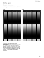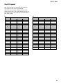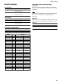
1
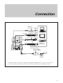
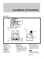
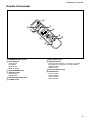
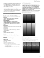
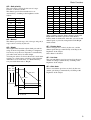
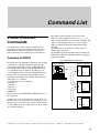
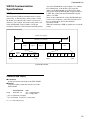
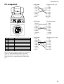
A-AYT-100-11 (1) Color Video Camera Technical Manual EVI-D100/D100P 2001 Sony Corporation Table of Contents Features ..................................................................... 3 Connection ................................................................. 4 Locations of Controls ............................................... 5 Basic Functions ......................................................... 7 Overview of Functions ................................................ 7 Initial Values and Backup ......................................... 11 Memory (Position preset) Function .......................... 12 Mode Condition ........................................................ 13 Command List ......................................................... 18 VISCA/RS-232C Commands ................................... 18 EVI-D100/P Commands ........................................... 25 D30/D31 Mode .......................................................... 40 Overview .................................................................. 40 Switching the Mode .................................................. 40 Accepting or Sending Back Commands ................... 41 Translating Parameters ............................................. 42 Specifications .......................................................... 46 Precautions .............................................................. 48 2 Overview Features • The CCD features 380,000 effective picture elements for the EVI-D100 and 440,000 for the EVI-D100P, which enables high-resolution shooting. • In addition to high-speed pan/tilt action, improvement of the noise reduction mechanism lets you use the Color Video Camera for a variety of purposes. • VISCA lets you operate your Color Video Camera from a computer. • Up to six combinations of the camera's position and status can be memorized. • A multi-function Remote Commander is provided. • Thanks to the D30/D31 emulation function, you can control your Color Video Camera using the same commands as those used for the EVI-D30/D31. 3 Connection Connection Video cable (not supplied) to Video input to VIDEO S-Video cable (1-751-416-11 not supplied) to S VIDEO to S-Video input VISCA cable (not supplied) 1) to RS-232C to VISCA IN Computer, TV or VCR with a video input jack to VISCA OUT To VISCA IN of other EVI-D100/Ps (when connecting to more than one camera) AC power adaptor MPA-AC1 (supplied) to AC outlet to DC IN 12V Power cord (supplied) 1) When the camera is connected to a computer with a VISCA cable (RS-232C, cross type), you can operate the camera with the computer. To obtain a cable, consult the dealer where you bought your camera. 4 Locations of Controls Locations of Controls Main Unit Front 3 4 1 2 Bottom Rear ON qs 1 2 qd qf 5 6 7 1 POWER lamp 2 STANDBY lamp 3 Lens 4 Sensor for the remote commander 5 BACKUP switch 6 VIDEO jack 7 S VIDEO jack 8 IR SELECT switch 9 DC IN 12 V jack 8 9 q; qa 0 VISCA OUT jack qa VISCA IN jack qs IR SELECT switch Set this switch to ON to allow the camera output signals transmitted from the Remote Commander to the Color Video Camera via the VISCA OUT jack to be output. When you don’t intend to do so, set it to OFF. qd D30/D31 mode switch Set this switch to ON to enable you to operate the Color Video Camera using the VISCA commands for the EVI-D30/D31. When you don’t intend to do so, set it to OFF. Note You cannot use some of the commands of the EVI-D30/D31 even if you set this switch to ON. qf Tripod hole 5 Locations of Controls Remote Commander 3 L UA AN 2 GH T M CK LI 7 3 6 R ES ET 2 5 ST D P RE AN SE -TI T LT PA N -T IL T 9 FA ST HO M E PR ES ET 4 1 PO SI TI O N SC TA DA 3 8 R EV RE 2 EN AU TO FA R BA 1 1 FO C U S N EA R C AM ER A SE LE C T PO W ER 6 M 0 1 CAMERA SELECT buttons 2 FOCUS buttons AUTO button FAR button NEAR button MANUAL button 3 DATA SCREEN button 4 PAN-TILT button Arrow buttons HOME button 5 L/R DIRECTION SET button 6 POWER switch W DIR 5 EC L/R TIO N SE T W T R M -E V1 00 T O ZO SL O W 4 7 BACK LIGHT button 8 POSITION buttons Numeric buttons (Button 1 also works as the STD button. Button 2 also works as the REV button.) PRESET button RESET button 9 PAN-TILT RESET button 0 ZOOM buttons SLOW T button SLOW W button FAST T button FAST W button 6 Basic Functions Basic Functions Overview of Functions Zoom The EVI-D100/P uses an 10× optical zoom lens. And its digital zoom function allows you to zoom up to 40×. • Optical 10×, f = 3.1 to 31 mm (F 1.8 to F 2.9) The horizontal angle of view is approximately 65 degrees (wide end) to 6.6 degrees (tele end). Digital zoom increases the picture element size and reduces the resolution. Extended control of zoom: • Direct zoom position • Zoom speed selection (8 speeds) • Digital zoom can be switched ON/OFF Focus The minimum focus distance is 100 mm at the optical wide end and 600 mm at the optical tele end, and is independent of the digital zoom. The AutoFocus (AF) function automatically adjusts the focus position to maximise the high frequency content of the picture in a center measurement area, taking into consideration the high luminance and strong contrast components. Note AVOID 24-hour continuous use of the autofocus. This may cause lens malfunction. All of these settings are performed via RS-232C control. If the RS-232C is not used, white balance, iris and gain adjustments will be carried out automatically, and the shutter speed will be fixed at 1/60 seconds for the EVI-D100 and 1/50 seconds for the EVI-D100P. Extended control of focus: • Direct focus position • Minimum focus distance limitation • Manual focus speed selection (8 speeds) • AutoFocus can be set to High or Low mode • One Push AF can be achieved in manual focus mode • HIGH AF High reaction speed of the AF. Use this mode when shooting fast moving objects. Recommended as the optimum mode for normal NON-CONTINUOUS use. • LOW AF Better focus stability. In low luminance conditions, the AF discontinues operation even when brightness changes, enabling stable images. White Balance • Auto Auto Tracing White Balance with limitations on R and B gain (3000 to 7500 K), to avoid fixing single color scenes as ‘white’ • ATW Auto Tracing White balance (2000 to 10000 K) • Indoor 3200 K • Outdoor 5800 K • One Push WB One Push White Balance 1) • Manual WB Manual control of R and B gain, 256 steps each 7 Basic Functions 1) The One Push White Balance mode is a fixed white balance mode that may be automatically readjusted only at the request of the user (One Push Trigger), assuming that a white subject, in correct lighting conditions, and occupying more than 1/2 of the image, is submitted to the camera. Selecting the One Push White Balance mode recalls the white balance data computed at the last One Push Trigger, if the BACKUP switch is set to ON and the camera has been connected to an AC outlet. The data is erased when the camera is disconnected from the AC outlet. Adjust the One Push White Balance again on the next time it is used. AE – Shutter priority The shutter speed can be set freely by the user to a total of 20 steps – 16 high speeds and 4 low speeds. When the slow shutter is set, the speed can be 1/30s (1/ 1 1 1 1 1 1 25s), /15s ( /12s), /8s ( /6s), /4s ( /3s) for NTSC (PAL) models. The picture output is read at a normal rate from the memory. The memory is updated at a low rate from the CCD. AF capability is low. In high speed mode, the shutter speed can be set up to 1/10,000s. The iris and gain are set automatically, according to the brightness of the subject. Automatic Exposure Mode This mode is set to “Full Auto” at shipment. Altogether 9 modes are available, including this one. • Full Auto Auto Iris and Gain, Fixed Shutter (EVI-D100: 1/60 sec., EVI-D100P: 1/50 sec.) • Shutter Priority 1) Variable Shutter Speed, Auto Iris and Gain (1/4 (EVI-D100) or 1/3 (EVI-D100P) to 1/10,000 sec., 20 steps, std. shutter: 16 steps, slow shutter: 4 steps) Data NTSC PAL 13 10000 10000 12 6000 6000 11 4000 3500 10 3000 2500 0F 2000 1750 0E 1500 1250 0D 1000 1000 0C 725 600 0B 500 425 0A 350 300 • Iris Priority Variable Iris (F1.8 to Close, 18 steps), Auto Gain and Shutter speed 09 250 215 08 180 150 07 125 120 • Gain Priority Variable Gain (–3 dB to 18 dB, 8 steps), Auto Iris and Fixed Shutter 06 100 100 05 90 75 04 60 50 • Manual Variable Shutter, Iris and Gain 03 30 25 02 15 12 01 8 6 00 4 3 • Bright Variable Iris and Gain (Close to F2.0, 17 steps at 0 dB: F1.8, 7 steps from 0 to 18 dB) • Iris Auto Variable Gain and Shutter speed • Shutter Auto Variable Iris and Gain • Gain Auto Variable Iris and Shutter speed 1) Flicker can be eliminated by setting shutter to t1/100s for NTSC models used in countries with a 50 Hz power supply frequency t1/120s for PAL models used in countries with a 60 Hz power supply frequency AE – Iris priority The iris can be set freely by the user to 18 steps between F1.8 and Close. The gain and shutter speed are set automatically, according to the brightness of the subject. Data Setting value Data Setting value 11 F1.8 08 F8 10 F2 07 F9.6 0F F2.4 06 F11 0E F2.8 05 F14 0D F3.4 04 F16 0C F4 03 F19 0B F4.8 02 F22 0A F5.6 01 F28 09 F6.8 00 CLOSE 8 Basic Functions AE – Gain priority The gain can be set freely by the user to 8 steps between –3 dB and +18 dB. The shutter speed is fixed and the iris is set automatically, according to the brightness of the subject. Data Iris Gain Data Iris Gain 17 F1.8 18 dB 0B F4.8 0 dB 16 F1.8 15 dB 0A F5.6 0 dB 15 F1.8 12 dB 09 F6.8 0 dB 14 F1.8 9 dB 08 F8 0 dB 13 F1.8 6 dB 07 F9.6 0 dB Data Setting value 12 F1.8 3 dB 06 F11 0 dB 07 18 dB 11 F1.8 0 dB 05 F14 0 dB 06 15 dB 10 F2 0 dB 04 F16 0 dB 05 12 dB 0F F2.4 0 dB 03 F19 0 dB 04 9 dB 0E F2.8 0 dB 02 F22 0 dB 03 6 dB 0D F3.4 0 dB 01 F28 0 dB 02 3 dB 0C F4 0 dB 00 CLOSE 0 dB 01 0 dB 00 –3 dB AE – Manual The shutter speed (20 steps), iris (18 steps) and gain (8 steps) can be set freely by the user. AE – Bright The bright control function adjusts both gain and iris using an internal algorithm, according to a brightness level freely set by the user. Exposure is controlled by gain when dark, and by iris when bright. As both gain and iris are fixed, this mode is used when exposing at a fixed camera sensitivity. Only when the AE mode is set to “Full Auto” or “Shutter Priority,” can you switch the mode to “Bright.” When switching from the Shutter Priority mode to the Bright mode, the shutter speed set in the Shutter Priority mode is maintained. After that, you can set the shutter speed as you wish, independent of the Bright mode control. AE – Shutter Auto The iris and gain are set freely by the user, and the shutter speed changes automatically according to the brightness of the subject. Slow shutter is disabled. AE – Iris Auto The gain and shutter speed are set freely by the user, and the iris changes automatically according to the brightness of the subject. AE – Gain Auto The iris and shutter speed are set freely by the user, and the gain changes automatically according to the brightness of the subject. Gain IRIS AGC OPEN MAX IRIS curve Gain curve CLOSE MIN Dark Bright Controlled by gain Controlled by IRIS Bright limit which controllable for this unit 9 Basic Functions Exposure Compensation Digital Effect Exposure compensation is a function which offsets the internal reference brightness level used in the AE mode, by steps of 1.5 dB. Digital Effect consists of the following functions. They are all executed via the field memory. • Still: Moving Image on Still Image • Flash: Continuous Still Image • Lumi.: Moving Images on Binaried Still Image • Trail: Afterimage Lag of Moving Subject Data Step Setting value 0E 7 10.5 dB 0D 6 9 dB 0C 5 7.5 dB 0B 4 6 dB 0A 3 4.5 dB 09 2 3 dB 08 1 1.5 dB 07 0 0 dB 06 –1 –1.5 dB 05 –2 –3 dB 04 –3 –4.5 dB 03 –4 –6 dB 02 –5 –7.5 dB 01 –6 –9 dB 00 –7 –10.5 dB Aperture Control Aperture control is a function which adjusts the enhancement of the edges of objects in the picture. There are 16 levels of adjustment, starting from “no enhancement.” When shooting text, this control may help by making them sharper. Back Light Compensation When the background of the subject is too bright, or when the subject is too dark due to shooting in the AE mode, back light compensation will make the subject appear clearer. Picture Effect It consists of the following functions. • Pastel: Pastel Image • Neg. Art: Negative/Positive Reversal • Sepia: Sepia Image • Black White: Monochrome Image • Solarize: Enhanced Contrast • Mosaic: Mosaic Image • Slim: Vertical Stretch • Stretch: Horizontal Stretch Others Mirror image The video output from the camera can be reversed left and right using this function. Freeze This function captures an image in the field memory of the camera so that this image can be output continuously. Memory (Position preset) Using the position preset function, 6 sets of camera shooting conditions can be stored and recalled. This function allows the desired zoom position, focus (auto, manual positions), white balance, shutter speed, bright control, iris, gain, exposure compensation, back light compensation, and aperture to be set instantaneously without having to adjust them individually each time. It also memorizes the settings for digital zoom on/off, slow shutter auto/manual. Backup Backs up the contents memorized by the memory (position preset) function and the camera functions when the power is turned OFF. The BACKUP switch can be switched as follows. • ON side Backs up for about one year when the internal battery is fully recharged. (Full recharge takes about 48 hours in power ON state.) • OFF side No back up. The switch is set to OFF at shipment. (All settings return to initial values when the power is turned on the next time.) Slow shutter – Auto/Manual When set to “Auto,” ensures that the slow shutter is set automatically when the brightness drops. Effective only when the AE mode is set to “Full Auto.” Set to “Slow Shutter Manual” at shipment. 10 Basic Functions Initial Values and Backup Initial values of functions of the EVI-D100/P are indicated in the “Initial values” column. An a in the “Backed up/Not backed up” column indicates that the setting is memorized in the camera. An × indicates that it is not. Backed up/Not backed up Category Mode/Position Initial values (a: Backed up, ×: Not backed up) Pan/Tilt Pan/Tilt Position Home position a Pan/Tilt Limit Position Zoom Zoom Position AE a On a Auto a AF Sens High/Low High a — a Near Limit Near end a WB Mode Auto a R/B Gain — a AE Mode Full Auto a Manual a Shutter Position — a Iris Position — a Gain Position — a Bright Position — a ExpComp On/Off Off a ExpComp Position ±0 a Back Light On/Off Off a 5 a Focus Position WB a Wide end Focus Mode Auto/Manual Digital Zoom On/Off Focus movable-range maximum Slow Shutter Auto/Manual Aperture Aperture Gain Effect Wide Mode Off LR Reverse On/Off Off Freeze On/Off Off Picture Effect Mode Off Digital Effect Mode Off Digital Effect Level 0 OSD Datascreen On/Off Off × × × × × × × IR IR_Receive On/Off On a1) IR_ReceiveReturn On/Off Off a1) AutoPowerOff Auto Power Off Timer 0 a1) Memory Position Preset Data — a VISCA VISCA Address 1 × 1),2) 1) The data items are backed up regardless of the BACKUP switch setting when you turn the power off using a VISCA command or the Remote Commander (standby mode). 2) When the camera is in the D30/D31 mode, the VISCA address is backed up. 11 Basic Functions Memory (Position Preset) Function You can save the camera settings and pan/tilt position using the supplied Remote Commander or the VISCA commands. Six channels are available. Data items saved in memory in the Color Video Camera Category Mode/Position Pan/Tilt Pan/Tilt Position Zoom Zoom Position Digital Zoom On/Off Focus Focus Mode Auto/Manual WB WB Mode Focus Position R/B Gain AE AE Mode Slow Shutter Auto/Manual Shutter Position Iris Position Gain Position Bright Position ExpComp On/Off ExpComp Position Back Light On/Off Aperture Aperture Gain 12 × × × × × × × × a × InquiryCommand (etc.) a a a a a a a a a a a a a a Other status 1) RC: Remote Commander D-Zoom On/Off Zoom Direct Zoom Tele/Wide/Stop Command RC VISCA Mode × × × × OFF Power × × × × Initializing Mode Condition 2 (Zoom) × × × × IFC × a a a a a VISCA a a a a RC1) Tele/Wide adjustment × × On Freeze 1) Initializing: The period from the instant you connect the camera to an AC outlet to the instant the camera outputs a video signal. Or the period between sending the Cam_PowerOn command and receiving the Completion message. 2) IFC: The period between sending the IF_Clear command and receiving the Reply Packet. a a a a CAM_PowerInq/Pantilt Mode Inq a a CAM_DeviceTypeInq/VersionInq BlockInquiry a a a a IR_Receive On/Off × IR_ReceiveReturn On/Off a Power Off AutoPowerOff setting a a a a a Address Set IF_Clear a IFC2) Power On Initializing1) a OFF Power a Command Mode Mode Condition 1 Mode Condition a a × × × × × × Memory Zoom Recall Direct execution execution Basic Functions 13 RC VISCA × × × × × × × × OFF Power × × × × × × × × Initializing × × × × × × × × IFC R/B Gain Reset/Up/Down/Direct One Push WB Trigger Auto/Indoor/Outdoor/ OnePushWB/ATW/Manual White Balance mode setting Command Mode × × × × × Initializing × OFF Power × × × IFC Mode Condition 4 (White Balance) Focus Near Limit AF Sens High/Low Focus Infinity One Push AF Trigger Focus Mode Auto/Manual Focus Direct Focus Far/Near/Stop Command Mode Mode Condition 3 (Focus) × × × Freeze On × × × Recall execution Memory a a a a × × a Auto a a × a a × a × a VISCA × × a Indoor a a a × a a a a RC Far/Near adjustment a × × × AF ON a × × × a × × On Freeze Memory × a × × × × × × × × a Outdoor × a a One Push White Balance mode a a × × a a × × Recall Direct execution execution Focus × × a ATW a × a Manual Basic Functions 14 × × × × × × × × × Gain Reset/Up/Down/ Direct Bright Reset/Up/Down/ Direct ExpComp On/Off ExpComp Reset/Up/Down/ Direct 3) Back Light On/Off × × × × × × × × × × IFC × × × × × × × × × × On Freeze × × × × × × × × × × Recall execution Memory 1): a only when the AE mode turns “Shutter Pri” into “Bright” 2): While activating a Digital Effect function, you cannot set functions related to Slow Shutter. 3): × when the Exposure Compensation function is set to off × × × Iris Reset/Up/Down/ Direct × × × × Initializing × × × × OFF Power Shutter Reset/Up/Down/ Direct 2) Slow Shutter Auto/Manual AE mode setting Bright Gain Pri/ Shutter Auto/ Iris Auto/Gain Auto Full Auto/Manual/ Shutter Pri/Iris Pri/ AE mode setting Command Mode Mode Condition 5 (Auto Exposure) a a a × × × × a a × a a a a a × × a Manual a a Full Auto × a a × × × a a a × a a × × a × a × a Pri Pri a Iris Shutter × a a × a × × a × a Pri Gain × a a × a a × a × a Auto Shutter Auto Exposure mode × a a × a × a a × a Iris Auto × a a × × a a a × a Gain Auto × a a a × × × 1) a × a Bright Basic Functions 15 Datascreen On/Off Digital Effect Level Off/Still/Flash/Lumi./Trail Digital Effect Solarize/Mosaic/Slim/Stretch Off/Pastel/NegArt/Sepia/B&W/ Picture Effect Freeze On/Off LR_Reverse On/Off Wide Off/Cinema/16:9Full Aperture Reset/Up/Down/Direct Command Mode × × × × × × × × × × Initializing × × × × × × OFF Power × × × × × × × × IFC × a a a a a a × a a a a a a a × a a a a a × a a a Digital Slow Recall Effect Shutter execution activated activated Memory × × × a × × × On Freeze Mode Condition 6 (Effect Setting, etc.) Basic Functions 16 Common Memory Reset × × × × × × × × × × × × × × × × × × × × × × × × × × × × × Initializing × Power OFF 1): a while the camera operates in the Tele/Wide zoom mode 2): a while the camera operates in the Far/Near focus mode RC VISCA Common Memory Set Memory Recall VISCA VISCA Pan-tiltDrive LimitSet RC VISCA Pan-tiltDrive LimitClear Pan-tiltDrive Reset RC VISCA VISCA Pan-tiltDrive RelativePosition Pan-tiltDrive Home VISCA VISCA Pan-tiltDrive Stop RC VISCA Transmit device Pan-tiltDrive AbsolutePosition Pan-tiltDrive Up/Down/Left/ Right/UpLeft/UpRight/ DownLeft/DownRight Command Mode × × × × × × × × × × × × × × × IFC a a a × × × 1) × 1) a a × × × × a a a a a a a a a a a a a a a a a × × × 2) × 2) a a a a a a a a a a a a a × × × × × × × × × × × × × × × × × × × a a × × a a a × a RC Up/Down/Left/ Right/UpLeft/ UpRight/ DownLeft/ DownRight Common Common VISCA Focus Freeze Zoom (manual) adjustOn ment Mode Condition 7 (Pan/Tilt, Memory Function) × × × × × × × × × × × a × × × × × × × × × × × × × × × × × × × × × × × × × × × a × × × × × × × × × × × × × a × × × × × × RC Home VISCA VISCA VISCA Absolute Relative Position Position Pan/Tilt movement × × × × × × × × × × × × × × × VISCA × × × × × × × × × × × × × × × RC Reset a a × × × × × × × × × × × × × VISCA a a × × × × × × × × × × × × × RC Memory Recall execution × × × × × × a a × × a × a a a Position detection error Basic Functions 17 Command List Command List VISCA1)/RS-232C Commands Use of RS-232C control software which has been developed based upon this command list may cause malfunction or damage to hardware and software. Sony Corporation is not liable for any such damage. Overview of VISCA The address of the controller is fixed at 0. The addresses of the peripheral devices are 1, 2, 3 ... in order, starting from the one nearest the controller. The address of the peripheral device is set by sending address commands during the initialization of the network. The VISCA devices each have a VISCA IN and VISCA OUT connector. Set the DTR input (the S output of the controller) of VISCA IN to H when controlling VISCA equipment from the controller. Fig. 1 VISCA network configuration In VISCA, the side outputting commands, for example, a computer, is called the controller, while the side receiving the commands, such as an EVI-D100/P, is called the peripheral device. The EVI-D100/P serves as a peripheral device in VISCA. In VISCA, up to seven peripheral devices like the EVI-D100/P can be connected to one controller using communication conforming to the RS-232C standard. The parameters of RS-232C are as follows. • Communication speed: 9600 bps • Data bits : 8 • Start bit : 1 • Stop bit : 1 • Non parity • MSB first Flow control using XON/XOFF and RTS/CTS, etc., is not supported. Peripheral devices are connected in a daisy chain. As shown in Fig. 1, the actual internal connection is a onedirection ring, so that messages return to the controller via the peripheral devices. The devices on the network are assigned addresses. VISCA Controller VISCA Equipment IN OUT IN OUT IN OUT ................................................................................................................................................................................................................................ 1) VISCA is a protocol which controls consumer camcorders developed by Sony. “VISCA” is a trademark of Sony Corporation. 18 Command List VISCA Communication Specifications VISCA packet structure The basic unit of VISCA communication is called a packet (Fig. 2). The first byte of the packet is called the header and comprises the sender’s and receiver’s addresses. For example, the header of the packet sent to the EVI-D100/P assigned address 1 from the controller (address 0) is hexadecimal 81H. The packet sent to the EVI-D100/P assigned address 2 is 82H. In the command list, as the header is 8X, input the address of the EVI-D100/P at X. The header of the reply packet from the EVI-D100/P assigned address 1 is 90H. The packet from the EVI-D100/P assigned address 2 is A0H. Some of the commands for setting EVI-D100/P units can be sent to all devices at one time (broadcast). In the case of broadcast, the header should be hexadecimal 88H. When the terminator is FFH, it signifies the end of the packet. Packet (3 to 16 bytes) Header Message (1 to 14 bytes) Byte 1 1 Sender’s address 0 Byte 2 Terminator FF Byte 3 Receiver’s address Bit 7 Bit 6 Bit 5 Bit 4 Bit 3 Bit 2 Bit 1 Bit 0 (MSB) (LSB) 1 1 1 1 1 1 1 1 Bit 7 Bit 6 Bit 5 Bit 4 Bit 3 Bit 2 Bit 1 Bit 0 (MSB) (LSB) Fig.2 Packet structure Command and inquiry ● Command Sends operational commands to the EVI-D100/P. ● Inquiry Used for inquiring about the current state of the EVI-D100/P. Note QQ1) = Command/Inquiry, RR2) = category code QQ = 01 (Command), 09 (Inquiry) RR = 00 (Interface), 04 (camera 1), 06 (Pan/Tilter) Inquiry 1) 2) Command Packet 8X QQ RR ... FF X = 1 to 7: EVI-D100/P address 19 Command List Responses for commands and inquiries Command execution cancel ● ACK message Returned by the EVI-D100/P when it receives a command. No ACK message is returned for inquiries. To cancel a command which has already been sent, send the IF_Clear command as the next command. To cancel one of any two commands which have been sent, use the cancel message. ● Completion message Returned by the EVI-D100/P when execution of commands or inquiries is completed. In the case of inquiry commands, it will contain reply data for the inquiry after the 3rd byte of the packet. If the ACK message is omitted, the socket number will contain a 0. Cancel Packet Note Cancel 8X 2Y FF Y = socket number X = 1 to 7: EVI-D100/P address, Y = socket number Reply Packet Ack X0 4Y FF Completion (commands) X0 5Y FF Completion (Inquiries) X0 5Y ... FF X = 9 to F: EVI-D100/P address + 8 The Command canceled error message will be returned for this command, but this is not a fault. It indicates that the command has been canceled. Note Y = socket number Y = socket number Y = socket number ● Error message When a command or inquiry command could not be executed or failed, an error message is returned instead of the completion message. Error Packet Description X0 6Y 01 FF Message length error (>14 bytes) X0 6Y 02 FF Syntax Error X0 6Y 03 FF Command buffer full X0 6Y 04 FF Command cancelled X0 6Y 05 FF No socket (to be cancelled) X0 6Y 41 FF Command not executable X = 9 to F: EVI-D100/P address + 8, Y = socket number Socket number When command messages are sent to the EVI-D100/P, it is normal to send the next command message after waiting for the completion message or error message to return. However to deal with advanced uses, the EVI-D100/P has two buffers (memories) for commands, so that up to two commands including the commands currently being executed can be received. When the EVI-D100/P receives commands, it notifies the sender which command buffer was used using the socket number of the ACK message. As the completion message or error message also has a socket number, it indicates which command has ended. Even when two command buffers are being used at any one time, an EVI-D100/P management command and some inquiry messages can be executed. The ACK message is not returned for these commands and inquiries, and only the completion message of socket number 0 is returned. 20 Command List VISCA Device Setting Command Before starting control of the EVI-D100/P, be sure to send the Address command and the IF_Clear command using the broadcast function. For VISCA network administration ● Address Sets an address of a peripheral device. Use when initializing the network, and receiving the following network change message. ● Network Change Sent from the peripheral device to the controller when a device is removed from or added to the network. The address must be re-set when this message is received. Packet Address 88 30 01 FF Network Change X0 38 FF X = 9 to F: EVI-D100/P address + 8 Note Always broadcasted. VISCA interface command ● IF_Clear Clears the command buffers in the EVI-D100/P and cancels the command currently being executed. Command Packet Reply Packet Note IF_Clear 8X 01 00 01FF X0 50 FF IF_Clear (broadcast) 88 01 00 01 FF 88 01 00 01 FF X = 1 to 7: EVI-D100/P address (For inquiry packet) X = 9 to F: EVI-D100/P address +8 (For reply packet) VISCA interface and inquiry ● IF_DeviceTypeInq Returns information on the VISCA interface. Inquiry Inquiry Packet Reply Packet Description IF_DeviceTypeInq 8X 09 00 02 FF Y0 50 GG GG HH HH JJ JJ KK FF GGGG = Vender ID (0020: Sony) HHHH = Model ID 0402: EVI-D30/D31 (When the D30/D31 mode is set to ON) 040D: EVI-D100/P JJJJ = ROM revision KK = Maximum socket # (02) X = 1 to 7: EVI-D100/P address (For inquiry packet) X = 9 to F: EVI-D100/P address +8 (For reply packet) 21 Command List Pin assignment • EVI-D100/P 1. DTR 1. CD 2. DSR 2. RXD 3. TXD 3. TXD 4. 5. 6. 7. 8. 4. 5. 6. 7. 8. 9. GND RXD GND IR OUT N.C. • EVI-D100/P 8 7 6 5 4 3 2 1 Windows D-sub 9 pin DTR GND DSR RTS CTS RI EVI or Macintosh 1. DTR 1. DTR 2. 3. 4. 5. 6. 7. 8. 2. 3. 4. 5. 6. 7. 8. DSR TXD GND RXD GND IR OUT N.C. DSR TXD GND RXD GND OPEN OPEN VISCA IN • EVI-D100/P No Pins Signals 1 DTR DataTransmission Ready (OUTPUT) 2 DSR Data Set Ready (INPUT) 3 TXD Transmit Data (OUTPUT) 4 GND Ground 5 RXD Receive Data (INPUT) 6 GND Ground 7 IR OUT IR Commander Signal (OUTPUT) 8 N.C. No Connection 1. 2. 3. 4. 5. 6. 7. 8. DTR DSR TXD GND RXD GND IR OUT N.C. Windows D-sub 25 pin 1. 2. 3. 4. 5. 6. 7. 20. FG TXD RXD RTS CTS DSR GND DTR IR OUT outputs the signals of the Remote Commander at 0 to 5 V when the IR OUT switch is set to ON. When the switch is set to OFF, signals input to the VISCA IN jack are output through the VISCA OUT jack. 22 Command List VISCA Command/ACK Protocol Command Command Message Reply Message Comments General Command 81 01 04 38 02 FF (Example) 90 41 FF (ACK)+90 51 FF (Completion) 90 42 FF 90 52 FF Returns ACK when a command has been accepted, and Completion when a command has been executed. 81 01 04 38 FF 90 60 02 FF (Syntax Error) Accepted a command which is not supported or a command lacking parameters. 81 01 04 38 02 FF (Example) 90 60 03 FF (Command Buffer Full) There are two commands currently being executed, and the command could not be accepted. 81 01 04 08 02 FF (Example) 90 61 41 FF (Command Not Executable) Could not execute the command in the current mode. (Example) 90 62 41FF Inquiry Command 81 09 04 38 FF (Example) 90 50 02 FF (Completion) ACK is not returned for the inquiry command. 81 09 05 38 FF 90 60 02 FF (Syntax Error) Accepted an incompatible command. (Example) Address Set 88 30 01 FF 88 30 02 FF Returned the device address to +1. IF_Clear(Broadcast) 88 01 00 01 FF 88 01 00 01 FF Returned the same command. IF_Clear (For x) 8x 01 00 01 FF z0 50 FF (Completion) ACK is not returned for this command. Command Cancel 8x 2y FF z0 6y 04 FF Returned when the command of the socket specified is canceled. Completion for the command canceled is not returned. (Command Canceled) z0 6y 05 FF (No Socket) Returned when the command of the specified socket has already been completed or when the socket number specified is wrong. 23 Command List VISCA Camera-Issued Messages ACK/Completion Messages Command Messages Comments ACK z0 4y FF (y:Socket No.) Returned when the command is accepted. Completion z0 5y FF (y:Socket No.) Returned when the command has been executed. z = Device address + 8 Error Messages Command Messages Comments Syntax Error z0 60 02 FF Returned when the command format is different or when a command with illegal command parameters is accepted. Command Buffer Full z0 60 03 FF Indicates that two sockets are already being used (executing two commands) and the command could not be accepted when received. Command Canceled z0 6y 04 FF (y:Socket No.) Returned when a command which is being executed in a socket specified by the cancel command is canceled. The completion message for the command is not returned. No Socket z0 6y 05 FF (y:Socket No.) Returned when no command is executed in a socket specified by the cancel command, or when an invalid socket number is specified. Command Not Executable z0 6y 41 FF (y:Socket No.) Returned when a command cannot be executed due to current conditions. For example, when commands controlling the focus manually are received during auto focus. Network Change Message Network Change Command Message Comments z0 38 FF Issued when power is being routed to the camera, or when the VISCA device is connected to or disconnected from the VISCA OUT jack. 24 Command List EVI-D100/P Commands EVI-D100/P Command List (1/4) Command Set Command Command Packet Comments AddressSet Broadcast 88 30 01 FF IF_Clear Broadcast 88 01 00 01 FF 8x 2p FF p: Socket No. (=1 or 2) On 8x 01 04 00 02 FF Power ON/OFF (Standby) Off (Standby) 8x 01 04 00 03 FF CAM_AutoPowerOff Direct 8x 01 04 40 0p 0q 0r 0s FF Auto Power Off pqrs: Power Off Timer 0000 (Timer Off) to FFFF (65535min) Initial value: 0000 The power automatically turns off if the camera does not receive any VISCA commands or any signals from the Remote Commander for the duration you set in the timer. CAM_Zoom Stop 8x 01 04 07 00 FF Zoom control CommandCancel CAM_Power CAM_Focus CAM_WB CAM_RGain Tele (Standard) 8x 01 04 07 02 FF Wide (Standard) 8x 01 04 07 03 FF Tele (Variable) 8x 01 04 07 2p FF Wide (Variable) 8x 01 04 07 3p FF Direct 8x 01 04 47 0p 0q 0r 0s FF pqrs: Zoom Position Optical zoom: 0000 (wide) to 4000 (tele) Digital zoom: 4000 (×1) to 7000 (×4) D-Zoom On 8x 01 04 06 02 FF Digital zoom ON/OFF D-Zoom Off 8x 01 04 06 03 FF Stop 8x 01 04 08 00 FF Far (Standard) 8x 01 04 08 02 FF Near (Standard) 8x 01 04 08 03 FF Far (Variable) 8x 01 04 08 2p FF p = Speed parameter, 0 (Low) to 7 (High), 8 steps Focus control p = Speed parameter, 0 (Low) to 7 (High), 8 steps Near (Variable) 8x 01 04 08 3p FF Direct 8x 01 04 48 0p 0q 0r 0s FF pqrs: Focus Position 1000 (Far) to 8400 (Near) Auto Focus 8x 01 04 38 02 FF AF ON/OFF Manual Focus 8x 01 04 38 03 FF Auto/Manual 8x 01 04 38 10 FF One Push Trigger 8x 01 04 18 01 FF One push AF trigger Infinity 8x 01 04 18 02 FF Forced infinity AF Sens High 8x 01 04 58 02 FF AF sensitivity High/Low AF Sens Low 8x 01 04 58 03 FF Near Limit 8x 01 04 28 0p 0q 0r 0s FF pqrs: Focus Near Limit Position 1000 (Far) to 8400 (Near) Auto 8x 01 04 35 00 FF Normal Auto Indoor 8x 01 04 35 01 FF Indoor mode Outdoor 8x 01 04 35 02 FF Outdoor mode One Push WB 8x 01 04 35 03 FF One push WB mode ATW 8x 01 04 35 04 FF Auto tracing white balance Manual 8x 01 04 35 05 FF Manual control mode One Push Trigger 8x 01 04 10 05 FF One push WB trigger Reset 8x 01 04 03 00 FF Manual control of R Gain Up 8x 01 04 03 02 FF Down 8x 01 04 03 03 FF Direct 8x 01 04 43 0p 0q 0r 0s FF pqrs: R Gain 0000 to 00ff, 256 steps 25 Command List EVI-D100/P Command List (2/4) Command Set Command Command Packet Comments CAM_BGain Reset 8x 01 04 04 00 FF Manual control of B Gain Up 8x 01 04 04 02 FF Down 8x 01 04 04 03 FF CAM_AE CAM_SlowShutter CAM_Shutter CAM_Iris CAM_Gain CAM_Bright CAM_ExpComp CAM_BackLight Direct 8x 01 04 44 0p 0q 0r 0s FF pqrs: B Gain 0000 to 00ff, 256 steps Full Auto 8x 01 04 39 00 FF Automatic exposure mode Manual 8x 01 04 39 03 FF Manual control mode Shutter Priority 8x 01 04 39 0A FF Shutter priority automatic exposure mode Iris Priority 8x 01 04 39 0B FF Iris priority automatic exposure mode Gain Priority 8x 01 04 39 0C FF Gain priority automatic exposure mode Bright 8x 01 04 39 0D FF Bright mode (Manual control) Shutter Auto 8x 01 04 39 1A FF Automatic shutter mode Iris Auto 8x 01 04 39 1B FF Automatic iris mode Gain Auto 8x 01 04 39 1C FF Automatic gain mode Auto 8x 01 04 5A 02 FF Slow shutter Auto/Manual Manual 8x 01 04 5A 03 FF Reset 8x 01 04 0A 00 FF Up 8x 01 04 0A 02 FF Shutter setting Down 8x 01 04 0A 03 FF Direct 8x 01 04 4A 0p 0q 0r 0s FF pqrs: Shutter Position 0000 (NTSC 1/4, PAL 1/3) to 0013 (1/10000 sec.), 20 steps Reset 8x 01 04 0B 00 FF Iris setting Up 8x 01 04 0B 02 FF Down 8x 01 04 0B 03 FF Direct 8x 01 04 4B 0p 0q 0r 0s FF pqrs: Iris Position 0000(close) to 0011(F1.8), 18 steps Reset 8x 01 04 0C 00 FF Gain setting Up 8x 01 04 0C 02 FF Down 8x 01 04 0C 03 FF Direct 8x 01 04 4C 0p 0q 0r 0s FF pqrs: Gain Position 0000(–3 dB) to 0007(+18 dB), 8 steps Reset 8x 01 04 0D 00 FF Bright setting Up 8x 01 04 0D 02 FF Down 8x 01 04 0D 03 FF Direct 8x 01 04 4D 0p 0q 0r 0s FF pqrs: Bright Position 0000 (close,0 dB) to 0017(F1.8,+18 dB), 24 steps at 3 dB On 8x 01 04 3E 02 FF Exposure compensation ON/OFF Off 8x 01 04 3E 03 FF Reset 8x 01 04 0E 00 FF Up 8x 01 04 0E 02 FF Exposure compensation amount setting Down 8x 01 04 0E 03 FF Direct 8x 01 04 4E 0p 0q 0r 0s FF pqrs: ExpComp Position 0000(–10.5 dB) to 000E(10.5 dB), 15 steps at 1.5 dB On 8x 01 04 33 02 FF Back light compensation ON/OFF Off 8x 01 04 33 03 FF 26 Command List EVI-D100/P Command List (3/4) Command Set Command Command Packet Comments CAM_Aperture Reset 8x 01 04 02 00 FF Aperture control Up 8x 01 04 02 02 FF Down 8x 01 04 02 03 FF Direct 8x 01 04 42 0p 0q 0r 0s FF pqrs: Aperture Gain 0000 to 000f, 16 steps, Initial value: 5 Off 8x 01 04 60 00 FF Wide mode setting Cinema 8x 01 04 60 01 FF CAM_Wide CAM_LR_Reverse 16:9 Full 8x 01 04 60 02 FF On 8x 01 04 61 02 FF Off 8x 01 04 61 03 FF CAM_Freeze On 8x 01 04 62 02 FF Off 8x 01 04 62 03 FF CAM_PictureEffect Off 8x 01 04 63 00 FF Pastel 8x 01 04 63 01 FF NegArt 8x 01 04 63 02 FF Sepia 8x 01 04 63 03 FF CAM_DigitalEffect B&W 8x 01 04 63 04 FF Solarize 8x 01 04 63 05 FF Mosaic 8x 01 04 63 06 FF Slim 8x 01 04 63 07 FF Stretch 8x 01 04 63 08 FF Off 8x 01 04 64 00 FF Still 8x 01 04 64 01 FF Flash 8x 01 04 64 02 FF Lumi. 8x 01 04 64 03 FF Trail 8x 01 04 64 04 FF EffectLevel 8x 01 04 65 pp FF Mirror image ON/OFF Still image ON/OFF Picture effect setting Digital effect setting pp: Effect Level 00 to 18(Flash,Trail), 00 to 20 (Still, Lumi.) CAM_Memory Datascreen IR_Receive IR_ReceiveReturn Reset 8x 01 04 3F 00 0p FF Set 8x 01 04 3F 01 0p FF Recall 8x 01 04 3F 02 0p FF On 8x 01 06 06 02 FF Off 8x 01 06 06 03 FF On/Off 8x 01 06 06 10 FF On 8x 01 06 08 02 FF Off 8x 01 06 08 03 FF On/Off 8x 01 06 08 10 FF On 8x 01 7D 01 03 00 00 FF Off 8x 01 7D 01 13 00 00 FF p: Memory Number (= 0 to 5) Display ON/OFF IR(remote controller) receive ON/OFF IR(remote controller) receive message ON/OFF 27 Command List EVI-D100/P Command List (4/4) Command Set Command Command Packet Comments Pan-tiltDrive Up 8x 01 06 01 VV WW 03 01 FF VV: Pan speed 01 to 18 Down 8x 01 06 01 VV WW 03 02 FF WW: Tilt Speed 01 to 14 Left 8x 01 06 01 VV WW 01 03 FF YYYY: Pan Position FA60 to 05A0 (center 0000) Right 8x 01 06 01 VV WW 02 03 FF ZZZZ: Tilt Position FE98 to 0168 (center 0000) UpLeft 8x 01 06 01 VV WW 01 01 FF UpRight 8x 01 06 01 VV WW 02 01 FF Pan-tiltLimitSet DownLeft 8x 01 06 01 VV WW 01 02 FF DownRight 8x 01 06 01 VV WW 02 02 FF Stop 8x 01 06 01 VV WW 03 03 FF AbsolutePosition 8x 01 06 02 VV WW 0Y 0Y 0Y 0Y 0Z 0Z 0Z 0Z FF RelativePosition 8x 01 06 03 VV WW 0Y 0Y 0Y 0Y 0Z 0Z 0Z 0Z FF Home 8x 01 06 04 FF Reset 8x 01 06 05 FF LimitSet 8x 01 06 07 00 0W 0Y 0Y 0Y 0Y 0Z 0Z 0Z 0Z FF W: 1 UpRight, 0 DownLeft YYYY: Pan Limit Position FA60 to 05A0 (center 0000) LimitClear 8x 01 06 07 01 0W 07 0F 0F 0F 07 0F 0F 0F FF ZZZZ: Tilt Limit Position FE98 to 0168 (center 0000) 28 Command List EVI-D100/P Inquiry Command List (1/2) InquiryCommand CommandPacket InquiryPacket Comments CAM_PowerInq 8x 09 04 00 FF y0 50 02 FF On y0 50 03 FF Off (Standby) CAM_AutoPowerOffInq 8x 09 04 40 FF y0 50 0p 0q 0r 0s FF pqrs: PowerOff Timer CAM_DZoomModeInq 8x 09 04 06 FF y0 50 02 FF Digital Zoom On y0 50 03 FF Digital Zoom Off CAM_ZoomPosInq 8x 09 04 47 FF y0 50 0p 0q 0r 0s FF pqrs: Zoom Position CAM_FocusModeInq 8x 09 04 38 FF CAM_FocusPosInq 8x 09 04 48 FF CAM_AFModeInq 8x 09 04 58 FF y0 50 02 FF Auto Focus On y0 50 03 FF Auto Focus Off y0 50 0p 0q 0r 0s FF pqrs: Focus Position y0 50 02 FF AF Sens High y0 50 03 FF AF Sens Low CAM_FocusNearLimitInq 8x 09 04 28 FF y0 50 0p 0q 0r 0s FF pqrs: Focus Limit Position CAM_WBModeInq 8x 09 04 35 FF y0 50 00 FF Auto y0 50 01 FF Indoor y0 50 02 FF Outdoor y0 50 03 FF OnePush y0 50 04 FF ATW y0 50 05 FF Manual CAM_RGainInq 8x 09 04 43 FF y0 50 0p 0q 0r 0s FF pqrs: R Gain CAM_BGainInq 8x 09 04 44 FF y0 50 0p 0q 0r 0s FF pqrs: B Gain CAM_AEModeInq 8x 09 04 39 FF CAM_SlowShutterModeInq 8x 09 04 5A FF y0 50 00 FF Full Auto y0 50 03 FF Manual y0 50 0A FF Shutter Priority y0 50 0B FF Iris Priority y0 50 0C FF Gain Priority y0 50 0D FF Bright y0 50 1A FF Shutter Auto y0 50 1B FF Iris Auto y0 50 1C FF Gain Auto y0 50 02 FF Auto y0 50 03 FF Manual CAM_ShutterPosInq 8x 09 04 4A FF y0 50 0p 0q 0r 0s FF pqrs: Shutter Position CAM_IrisPosInq 8x 09 04 4B FF y0 50 0p 0q 0r 0s FF pqrs: Iris Position CAM_GainPosInq 8x 09 04 4C FF y0 50 0p 0q 0r 0s FF pqrs: Gain Position CAM_BrightPosInq 8x 09 04 4D FF y0 50 0p 0q 0r 0s FF pqrs: Bright Position 29 Command List EVI-D100/P Inquiry Command List (2/2) InquiryCommand CommandPacket InquiryPacket Comments CAM_ExpCompModeInq 8x 09 04 3E FF y0 50 02 FF On y0 50 03 FF Off CAM_ExpCompPosInq 8x 09 04 4E FF y0 50 0p 0q 0r 0s FF pqrs: ExpCompPosition CAM_BackLightModeInq 8x 09 04 33 FF y0 50 02 FF On y0 50 03 FF Off CAM_ApertureInq 8x 09 04 42 FF y0 50 0p 0q 0r 0s FF pqrs: Aperture Gain CAM_WideModeInq 8x 09 04 60 FF CAM_LR_ReverseModeInq 8x 09 04 61 FF CAM_FreezeModeInq 8x 09 04 62 FF CAM_PictureEffectModeInq CAM_DigitalEffectModeInq 8x 09 04 63 FF 8x 09 04 64 FF y0 50 00 FF Off y0 50 01 FF Cinema y0 50 02 FF 16:9 Full y0 50 02 FF On y0 50 03 FF Off y0 50 02 FF On y0 50 03 FF Off y0 50 00 FF Off y0 50 01 FF Pastel y0 50 02 FF NegArt y0 50 03 FF Sepia y0 50 04 FF B&W y0 50 05 FF Solarize y0 50 06 FF Mosaic y0 50 07 FF Slim y0 50 08 FF Stretch y0 50 00 FF Off y0 50 01 FF Still y0 50 02 FF Flash y0 50 03 FF Lumi. y0 50 04 FF Trail CAM_DigitalEffectLevelInq 8x 09 04 65 FF y0 50 pp FF pp: Effect Level CAM_MemoryInq 8x 09 04 3F FF y0 50 0p FF p: Last Access Memory No. DatascreenInq 8x 09 06 06 FF y0 50 02 FF On y0 50 03 FF Off Pan-tiltModeInq 8x 09 06 10 FF y0 50 pq rs FF pqrs: Pan/Tilter Status Pan-tiltMaxSpeedInq 8x 09 06 11 FF y0 50 ww zz FF ww = Pan Max Speed Pan-tiltPosInq 8x 09 06 12 FF y0 50 0w 0w 0w 0w wwww = Pan Position 0z 0z 0z 0z FF zzzz = Tilt Position zz = Tilt Max Speed VideoSystemInq CAM_DeviceTypeInq / VersionInq 8x 09 06 23 FF 8x 09 00 02 FF y0 50 00 FF NTSC y0 50 01 FF PAL y0 50 gg gg gggg = Vender ID (0001:Sony) hh hh jj jj kk FF hhhh = Model ID jjjj = ROM Version kk = Socket Number (=2) IR_ReceiveReturn y0 07 7D 01 04 00 FF Power ON/OFF y0 07 7D 01 04 07 FF Zoom tele/wide y0 07 7D 01 04 38 FF AF On/Off y0 07 7D 01 04 33 FF CAM_Backlight y0 07 7D 01 04 3F FF CAM_Memory y0 07 7D 01 06 01 FF Pan_tiltDrive 30 Command List EVI-D100/P Block Inquiry Command List Lens control system inquiry commands (1/2) ....... Command Packet 8x 09 7E 7E 00 FF Byte 0 1 2 Bit Comments 7 7 0 6 6 0 Bit Comments Byte 5 5 0 4 4 0 3 y0 6 2 1 1 0 0 7 7 0 6 6 0 5 5 0 4 0 4 3 50 7 2 1 1 0 0 0 7 0 6 0 6 0 5 0 5 0 4 0 4 0 3 8 3 2 Zoom Position (HH) 1 Focus Position (HH) 0 0 7 0 7 0 6 0 6 0 5 0 5 0 4 0 4 0 3 2 1 9 3 2 Zoom Position (HL) 1 Focus Position (HL) 0 0 7 0 7 0 6 0 6 0 5 0 5 0 4 0 4 0 3 2 1 10 3 2 Zoom Position (LH) 1 Focus Position (LH) 0 0 5 Focus Near Limit (L) 7 1 4 Focus Near Limit (H) 3 2 2 3 3 2 7 0 7 0 6 0 6 0 5 0 5 0 4 0 4 0 3 2 1 0 Zoom Position (LL) 11 3 2 1 Focus Position (LL) 0 31 Command List Lens control system inquiry commands (2/2) ....... Command Packet 8x 09 7E 7E 00 FF Byte 12 13 14 Bit Comments 7 0 6 0 5 0 4 0 3 0 2 0 1 0 0 0 7 0 6 0 5 0 4 0 3 0 2 AF Sens 1:High 0:Low 1 Digital Zoom 1:On 0:Off 0 Focus Mode 1:Auto 0:Manual 7 0 6 0 5 0 4 0 3 0 2 0 1 Focus Command 1:Executing 0: Stopped 0 Zoom Command 1:Executing 0: Stopped 7 6 5 15 4 3 FF 2 1 0 32 Command List Camera control system inquiry commands (1/2) .. Command Packet 8x 09 7E 7E 01 FF Byte 0 1 2 Bit Comments 7 7 0 6 6 0 Bit Comments Byte 5 5 0 4 4 0 3 y0 6 2 WB Mode 1 1 0:Auto 1:Indoor 2:Outdoor 0 0 3:OnePushWB 4:ATW 5:Manual 7 7 0 6 6 0 5 5 0 4 0 4 3 50 7 2 1 1 0 0 Aperture Gain 7 0 7 0 6 0 6 0 5 0 5 0 4 0 8 3 R Gain (H) 0 4 Exposure Mode 3 00:Full Auto 03:Manual 2 0A:ShutterPriority 0B:IrisPriority 1 0C:GainPriority 0D:Bright 0 1A:ShutterAuto 1B:IrisAuto 1C:GainAuto 0 7 6 0 6 5 0 5 Iris Command 1:Valid 0:Invalid 0 4 Shutter Command 1:Valid 0:Invalid 3 3 Bright Command 1:Valid 0:Invalid 2 2 Back Light 1:On 0:Off 1 Exposure Comp. 1:On 0:Off 0 0 Slow Shutter 1:Auto 0:Manual 7 0 7 0 6 0 6 0 5 0 5 0 0 4 7 4 1 4 9 R Gain (L) 10 3 2 1 0 Gain Command 1:Valid 0:Invalid 3 2 B Gain (H) Shutter Position 1 0 0 5 3 2 1 4 0 2 2 3 3 7 0 7 0 6 0 6 0 5 0 5 0 4 0 4 0 3 2 1 0 11 3 2 B Gain (L) 1 Iris Position 0 33 Command List Camera control system inquiry commands (2/2) .. Command Packet 8x 09 7E 7E 01 FF Byte 12 Bit Comments 7 0 6 0 5 0 4 0 3 0 2 1 Gain Position 0 13 7 0 6 0 5 0 4 3 2 Bright Position 1 0 14 7 0 6 0 5 0 4 0 3 2 1 Exposure Comp. Position 0 7 6 5 15 4 3 FF 2 1 0 34 Command List Other inquiry commands (1/2) ................................ Command Packet 8x 09 7E 7E 02 FF Byte 0 1 2 Bit Bit Comments 7 7 0 6 6 0 4 5 5 0 4 0 y0 3 6 3 0 2 2 Digital Effect Mode 1 1 0:Off 1:Still 2:Flash 3:Lumi. 4:Trail 0 0 7 7 0 6 6 0 5 5 0 4 50 3 7 4 3 2 2 1 1 0 0 Digital Effect Level 7 0 7 0 6 0 6 0 5 0 5 0 4 0 4 0 3 0 3 0 2 0 2 0 1 0 1 0 0 0 8 Power 1:On 0:Off 7 0 7 0 6 0 6 0 5 0 5 0 4 0 4 0 9 3 Freeze 1:On 0:Off 3 0 2 LR Reverse 1:On 0:Off 2 0 1 Wide 16:9 Full 1:On 0:Off 1 0 0 Wide Cinema 1:On 0:Off 0 0 7 0 7 0 6 0 6 0 5 0 5 0 4 0 4 0 3 0 2 0 3 2 5 Byte 4 0 3 Comments 0 10 Data screen 1:On, 0:Off 1 0 1 0 0 0 0 0 7 0 7 0 6 0 6 0 5 0 5 0 4 0 4 0 3 0 3 0 11 2 Picture Effect Mode 2 0 1 0:Off 1:Pastel 2:Neg.Art 3:Sepia 4:B&W 1 0 0 5:Solarize 6:Mosaic 7:Slim 8:Stretch 0 0 35 Command List Other inquiry commands (2/2) ................................ Command Packet 8x 09 7E 7E 02 FF Byte 12 Bit Comments 7 0 6 0 5 0 4 0 3 0 2 0 1 0 0 13 14 System 1:PAL 0:NTSC 7 0 6 0 5 0 4 0 3 0 2 0 1 0 0 0 7 0 6 0 5 0 4 0 3 0 2 0 1 0 0 0 7 6 5 15 4 3 FF 2 1 0 36 Command List VISCA Command Setting Values NTSC Bright Exposure control NTSC Shutter Speed Iris Gain PAL 13 10000 10000 12 6000 6000 11 4000 3500 10 3000 2500 0F 2000 1750 0E 1500 1250 0D 1000 1000 0C 725 600 0B 500 425 0A 350 300 09 250 215 08 180 150 07 125 120 06 100 100 05 90 75 04 60 50 03 30 25 02 15 12 01 8 6 00 4 3 11 F1.8 10 F2 0F F2.4 0E F2.8 0D F3.4 0C F4 0B F4.8 0A F5.6 09 F6.8 08 F8 07 F9.6 06 F11 05 F14 04 F16 03 F19 02 F22 01 F28 00 CLOSE 07 18 dB 06 15 dB 05 12 dB 04 9 dB 03 6 dB 02 3 dB 01 0 dB 00 –3 dB Exposure Comp. PAL 17 F1.8 18 dB 16 F1.8 15 dB 15 F1.8 12 dB 14 F1.8 9 dB 13 F1.8 6 dB 12 F1.8 3 dB 11 F1.8 0 dB 10 F2 0 dB 0F F2.4 0 dB 0E F2.8 0 dB 0D F3.4 0 dB 0C F4 0 dB 0B F4.8 0 dB 0A F5.6 0 dB 09 F6.8 0 dB 08 F8 0 dB 07 F9.6 0 dB 06 F11 0 dB 05 F14 0 dB 04 F16 0 dB 03 F19 0 dB 02 F22 0 dB 01 F28 0 dB 00 CLOSE 0 dB 0E 7 10.5 dB 0D 6 9 dB 0C 5 7.5 dB 0B 4 6 dB 0A 3 4.5 dB 09 2 3 dB 08 1 1.5 dB 07 0 0 dB 06 –1 –1.5 dB 05 –2 –3 dB 04 –3 –4.5 dB 03 –4 –6 dB 02 –5 –7.5 dB 01 –6 –9 dB 00 –7 –10.5 dB 37 Command List Zoom values and focal length (for reference) Zoom values Focal length1) (mm) 0000h 3.1 0E6Dh 4.65 188Eh 6.2 2507h 9.3 2B82h 12.4 3130h 15.5 352Eh 18.6 385Dh 21.7 3B48h 24.8 3E01h 27.9 4000h 31 5000h 41.3 6000h 62 7000h 124 1) Values when an object is 2 m away from the front surface of the lens Focus values (Focus Near limit values) and object distance (for reference) Focus value (limit value) Object distance1) (m) 1161h 20 116Dh 18 122Ah 16 123Ch 14 12F3h 12 13C2h 10 151Eh 8 1536h 6 1844h 4 226Fh 2 3F2Ah 1.5 40AAh 1 62C9h 0.5 82C1h 0.1 1) Distance between the front surface of the lens and an object 38 Command List Lens control 0000 (Optical Wide end) to 4000 (Optical Tele end) 4000 (Digital Zoom ×1) to 7000 (Digital Zoom ×4) Focus Position 1000 (Far) to 8400 (Near) Focus Near Limit 1000 (Far) to 8400 (Near) Zoom Position Note: The lower one byte is fixed at 00. Others R,B gain 00~FF Aperture 00~0F Effect Level (Digital Effect Level) STILL 00~20 FLASH 00~18 LUMI. 00~20 TRAIL 00~18 Pan/Tilter Status Code List P Q R S 0––– –––– 0––– –––1 Pan has reached the left endpoint. 0––– –––– 0––– ––1– Pan has reached the right endpoint. 0––– –––– 0––– –1–– Tilt has reached the top endpoint. 0––– –––– 0––– 1––– Tilt has reached the bottom endpoint. 0––– –––– ––0 0 –––– Pan is normal. 0––– –––– ––0 1 –––– Pan has a position detection error. 0––– –––– ––1 0 –––– Pan has a mechanical problem. 0––– ––0 0 0––– –––– Tilt is normal. 0––– ––0 1 0––– –––– Tilt has a position detection error. 0––– ––1 0 0––– –––– Tilt has a mechanical problem. 0––– 0 0–– 0––– –––– No movement command 0––– 0 1–– 0––– –––– Pan-Tilt is moving. 0––– 1 0–– 0––– –––– Pan-Tilt operation is completed. 0––– 1 1–– 0––– –––– Pan-Tilt operation failed. 0–0 0 –––– 0––– –––– Not initialized 0–0 1 –––– 0––– –––– Initializing 0–1 0 –––– 0––– –––– Initialization completed 0–1 1 –––– 0––– –––– Initialization failed ( – : Optional) 39 Command List D30/D31 Mode Overview Switching the Mode The D30/D31 mode allows you to control the EVID100/P using VISCA commands for the EVI-D30/ D31. Most of the VISCA commands for the EVI-D100/P correspond to one for the EVI-D30/D31. However, some of the VISCA commands for the EVI-D100/P are different from those for the EVI-D30/D31 in definitions of parameters. When you send those commands to an EVI-D100/P whose D30/D31 mode is set to ON, the camera translates the parameters for the EVI-D30/D31 to those for the EVI-D100/P and executes the command. The following parameters are subject to translation. You can switch the D30/D31 mode ON or OFF by switching the D30/D31 mode switch at the bottom of the EVI-D100/P. To change the D30/D31 mode setting, move the D30/D31 mode switch to ON or OFF while the camera’s power is off or the camera is in standby mode. Then, turn the power on by connecting the camera to an AC outlet or by using the VISCA commands or the Remote Commander. If you change the switch setting while the camera’s power is on, the mode of the camera will not change. At the moment you turn the D30/D31 mode on or off, the data backed up in the camera is erased and the settings return to their initial values. • Zoom speed • Zoom position • Focus position • Shutter speed • Pan-tilt speed • Pan-tilt position Notes • Even if you set the D30/D31 mode to ON, the EVID100/P may not emulate the EVI-D30/D31 perfectly. This is caused by differences in hardware between the two models. • The functions that are provided with the EVI-D30/ D31 but not with the EVI-D100/P cannot be executed. 40 D30/31 Mode Command List Accepting or Sending Back Commands When accepting commands Type of command D30/D31 mode on Common to both the D30/D31 and Common parameters Accepts as is D30/D31 mode off D100/P Different parameters Translates the D30/D31’s parameters to those of the D100/P Accepts as is CAM_Memory Reset Memorized data items are erased and camera settings return to initial values Memorized data items are erased Refuses and sends back the Accepts as is Only for the D100/P NotExecutable message Only for the D30/D31 Refuses and sends back the Refuses and sends back the NotExecutable message SyntaxError message Type of command D30/D31 mode on D30/D31 mode off Common to both the D30/D31 and Common parameters Sends back parameters common to both the D30/D31 and D100/P When accepting inquiry commands D100/P Different parameters Only for the D100/P Sends back the D30/D31’s parameters translated from those of the D100/P Sends back the D100/P’s parameters Refuses and sends back the Sends back the D100/P’s parameters NotExecutable message Only for the D30/D31 Refuses and sends back the Refuses and sends back the NotExecutable message SyntaxError message 41 D30/31 Mode Command List Translating Parameters Zoom speed Focus position Cameras Parameters EVI-D30/D31 1000h (FAR) to 9FFFh (NEAR, 1 cm) EVI-D100/P 1000h (FAR) to 8400h (NEAR, 10 cm) Translation of commands Cameras Parameters EVI-D30/D31 02h (Min. speed) to 07h (Max. speed) Accepted parameters Translation EVI-D100/P 00h (Min. speed) to 07h (Max. speed) Values less than 8400h Accepts as is Values greater than 8400h Translates to 8400h Translation of commands Accepted parameters Translation 00h, 01h Translates to 02h Values greater than 02h Accepts as is The actual focus position does not match the value that is defined by the D30/D31’s parameters. Translation when answering inquiry commands Zoom position Cameras Parameters EVI-D30/D31 0000h (WIDE) to 03FFh (TELE) EVI-D100/P 0000h (WIDE) to 7000h (TELE, digital 4×) Parameters Translation 1000h to 8400h Sends back parameters as is During the period from the instant the camera accepts the CAM_Focus Direct command at a value grater than 8400h to the instant the camera accepts another command to define the focus position, it sends back the current D30/D31 parameters. Translation of commands Accepted parameters Translation 0000h to 03FFh Translates within a rage of 08D0h to 5700h Wide D30/D31 D100/P 0 Tele 0 370 8D0 Wide end 4000 3FF 5700 Tele end 7000 Digital 4× The EVI-D100/P translates the parameters to let the camera obtain the same zoom position that is defined by the D30/D31’s parameter. The digital zoom function is always set to ON. However, when you use the CAM_Zoom Tele/Wide command or the Remote Commander, the available zoom range is equal to the zoom range of the EVID100/P (0000h to 7000h). Translation when answering inquiry commands Parameters Translation 0000h to 7000h Translates within a rage of 0000h to 03FFh The D100/P’s parameters are translated to those of the D30/D31. However, even if the zoom position value is less than 08D0h (closer to the wide side), the camera sends back 0000h to the controller. On the other hand, even if that value is greater than 5700h (closer to the telephoto side), the camera sends back 03FFh. 42 D30/31 Mode Command List Shutter speed Translation of commands The EVI-D100/P translates the D30/D31’s parameters to D100/P parameters in accordance with the table below. NTSC PAL EVI-D30 EVI-D100 EVI-D31 Parameters Shutter speed EVI-D100P Parameters Shutter speed Parameters Shutter speed 0000h (1/60) b 0004h (1/60) 0000h (1/50) b Parameters Shutter speed 0004h (1/50) 0001h (1/60) b 0004h (1/60) 0001h (1/60) b 0004h (1/50) 0002h (1/75) b 0004h (1/60) 0002h (1/75) b 0005h (1/75) 0003h (1/90) b 0005h (1/90) 0003h (1/90) b 0006h (1/100) 0004h (1/100) b 0006h (1/100) 0004h (1/100) b 0006h (1/100) 0005h (1/125) b 0007h (1/125) 0005h (1/120) b 0007h (1/120) 0006h (1/150) b 0007h (1/125) 0006h (1/150) b 0008h (1/150) 0007h (1/180) b 0008h (1/180) 0007h (1/180) b 0008h (1/150) 0008h (1/215) b 0008h (1/180) 0008h (1/215) b 0009h (1/215) 0009h (1/250) b 0009h (1/250) 0009h (1/250) b 0009h (1/215) 000Ah (1/300) b 0009h (1/250) 000Ah (1/300) b 000Ah (1/300) 000Bh (1/350) b 000Ah (1/350) 000Bh (1/350) b 000Ah (1/300) 000Ch (1/425) b 000Ah (1/350) 000Ch (1/425) b 000Bh (1/425) 000Dh (1/500) b 000Bh (1/500) 000Dh (1/500) b 000Bh (1/425) 000Eh (1/600) b 000Bh (1/500) 000Eh (1/600) b 000Ch (1/600) 000Fh (1/725) b 000Ch (1/725) 000Fh (1/725) b 000Ch (1/600) 0010h (1/850) b 000Ch (1/725) 0010h (1/850) b 000Dh (1/1000) 0011h (1/1000) b 000Dh (1/1000) 0011h (1/1000) b 000Dh (1/1000) 0012h (1/1250) b 000Dh (1/1000) 0012h (1/1250) b 000Eh (1/1250) 0013h (1/1500) b 000Eh (1/1500) 0013h (1/1500) b 000Eh (1/1250) 0014h (1/1750) b 000Eh (1/1500) 0014h (1/1750) b 000Fh (1/1750) 0015h (1/2000) b 000Fh (1/2000) 0015h (1/2000) b 000Fh (1/1750) 0016h (1/2500) b 000Fh (1/2000) 0016h (1/2500) b 0010h (1/2500) 0017h (1/3000) b 0010h (1/3000) 0017h (1/3000) b 0010h (1/2500) 0018h (1/3500) b 0010h (1/3000) 0018h (1/3500) b 0011h (1/3500) 0019h (1/4000) b 0011h (1/4000) 0019h (1/4000) b 0011h (1/3500) 001Ah (1/6000) b 0012h (1/6000) 001Ah (1/6000) b 0012h (1/6000) 001Bh (1/10000) b 0013h (1/10000) 001Bh (1/10000) b 0013h (1/10000) Translation when answering inquiry commands The EVI-D100/P translates its parameters to the D30/ D31’s parameters and sends them back. However, during the period from the instant the camera accepts the CAM_Shutter Direct command to the instant the camera accepts another CAM_Shutter or CAM_AE command, it sends back the current D30/D31 parameters. 43 D30/31 Mode Command List Pan/tilt speed The actual speed that is defined by the parameters corresponds to that of the EVI-D30/D31. When the camera accepts commands such as PantiltDrive Home, Reset, or CAM_Memory Recall, the operation speed is equal to the speed when the D30/ D31 mode is OFF. Pan Tilt Speed (deg/sec) Speed (deg/sec) Parameters D100/P D30/D31 Parameters D100/P 01h 2.0 b 3.3 01h 2.0 b D30/D31 2.5 02h 2.4 b 6.7 02h 2.4 b 5.0 03h 3.0 b 10.0 03h 3.0 b 7.5 04h 3.7 b 13.3 04h 3.7 b 10.0 05h 4.7 b 16.7 05h 4.7 b 12.5 06h 6.1 b 20.0 06h 6.1 b 15.0 07h 7.4 b 23.3 07h 7.4 b 17.5 08h 9.1 b 26.7 08h 9.1 b 20.0 09h 11 b 30.0 09h 11 b 22.5 0Ah 14 b 33.3 0Ah 14 b 25.0 0Bh 18 b 36.7 0Bh 18 b 27.5 0Ch 22 b 40.0 0Ch 22 b 30.0 0Dh 27 b 43.3 0Dh 27 b 32.5 0Eh 34 b 46.7 0Eh 34 b 35.0 0Fh 42 b 50.0 0Fh 42 b 37.5 10h 52 b 53.3 10h 52 b 40.0 11h 65 b 56.7 11h 65 b 42.5 12h 81 b 60.0 12h 81 b 45.0 13h 100 b 63.3 13h 100 b 47.5 14h 125 b 66.7 14h 125 b 50.0 15h 155 b 70.0 16h 190 b 73.3 17h 240 b 76.7 18h 300 b 80.0 44 D30/31 Mode Command List Pan/tilt position Translation when answering inquiry commands The camera sends back values that are calculated by inverse conversion performed when the camera accepts commands. Pan position Cameras Parameters EVI-D30/D31 FC90h (–100 degrees) to EVI-D100/P FA60h (–100 degrees) to 0370h (+100 degrees) Note Repetitive use of the Relative position command may increase the variance that is accumulated from translation. 05A0h (+100 degrees) Tilt position Cameras Parameters EVI-D30/D31 FED4h (–25 degrees) to 012Ch (+25 degrees) EVI-D100/P FE98h (–25 degrees) to 0168h (+25 degrees) Example When you execute the Relative position command 88 times, one step after another to turn the camera to the right side: Cameras Translation of commands Accepting parameters Translation Pan position Multiplies received parameters by 18/11 Tilt position Multiplies received parameters by 6/5 D30/D31 Pan Tilt FA60h – … – FE15h FE98h … … b FFFBh FFFCh FFFEh b FFFDh FFFEh FFFFh b FFFEh FFFFh 0000h b 0000h 0000h 0001h b 0002h 0001h 0002h b 0003h 0002h 0003h b 0005h 0004h 0004h b 0007h 0005h 0005h b 0008h 0006h 0006h b 000Ah 0007h 0007h b 000Bh 0008h 0008h b 000Dh 0009h b … FED4h b … FFFDh 0009h b 000Fh 000Bh 000Ah b 0010h 000Ch 000Bh b 0012h 000Dh … … 01EBh 0168h … – 05A0h – … 012Ch b … 0370h EVI-D30/D31 Turns to the right side by 10 degrees. EVI-D100/P whose D30/D31 mode is ON Turns to the right side by 12.2 degrees. D100/P Pan/Tilt FC90h Results b 45 Specifications Specifications System Video signal EVI-D100: NTSC Color, JEITA standards EVI-D100P: PAL Color, CCIR standards Picture element 1/4 inch color CCD (Total picture elements: EVI-D100: Approx. 410,000 EVI-D100P: Approx. 470,000) (Effective picture elements: EVI-D100: Approx. 380,000 EVI-D100P: Approx. 440,000) Lens 10× (Optical), 40× (Digital) f=3.1 to 31 mm, F1.8 to F2.9 Horizontal angle: 6.6 degrees to 65 degrees Minimum object distance WIDE end : 100 mm TELE end : 600 mm Minimum illumination 3.5 lx (F1.8)/with 50 IRE Illumination range 3.5 to 100,000 lx Shutter speed EVI-D100: 1/4 to 1/10,000 s (VISCA control) EVI-D100P: 1/3 to 1/10,000 s (VISCA control) Horizontal resolution NTSC : 470 TV (WIDE end) PAL : 460 TV (WIDE end) Video S/N 50 dB Pan/tilt action Horizontal: ±100 degrees Maximum speed: 300 degrees/s, Vertical: ±25 degrees Maximum speed: 125 degrees/s (in 5/72 (0.07) degree increments) S video output 4 pin mini DIN (1) Input/output control terminals RS-232C (input: 1, output: 1), 8 pin mini DIN, 9600 bps Data: 8 bit Stop bit: 1 Power terminal JEITA type4 General Input voltage DC 12 V (DC 10.8 to 13 V) Current consumption 1.1 A (at 12 V DC) Operating temperature 0 °C to 40 °C (32 °F to 104 °F) Storage temperature – 20 °C to 60 °C (– 4 °F to 140 °F) Dimensions Video camera: 113 × 120 × 132 mm (4 1/2 × 4 3/4 × 5 1/4 in.) (w/h/d) Remote Commander: 56 × 26 × 210 mm (2 1/4 × 1 1/16 × 8 3/8 in.) (w/h/d) Mass Video camera: 860 g (1 lb 14 oz.) Remote Commander: 109 g (3.8 oz.) Installation angle ±15 degrees to a horizontal surface Supplied accessories AC power adaptor (1) Power cord (1) Remote Commander (1) Velcro tape (3 sets) Operating Instructions (1) Design and specifications are subject to change without notice. Input/output terminals Video output RCA pin jack (1), 1Vpp, 75 ohm unbalanced Synchronization: negative 46 Specifications Dimensions 87.5 (3 7/16) 1.7 (1/16) 132 (5 3/16) 136.5 (5 3/8) Tripod hole 1/4-20UNC (ISO1222) Bottom 113 (4 7/16) 116.5 (4 19/32) Top 20 (25/32) 113 (4 7/16) 128 (5 1/32) Right side 120 (4 23/32) Front φ 4.5 (3/16) 44.4 (1 3/4) 94.9 (3 3/4) Unit: mm (inches) 47 Specifications Precautions Software Other Use of the demonstration software developed by Sony Corporation or use of the software with customer developed application software may damage hardware, the application program or the camera. Sony Corporation is not liable for any damages under these conditions. Do not apply excessive voltage. (Use only the specified voltage.) Otherwise, you may get an electric shock or a fire may occur. In case of abnormal operation, contact your authorized Sony dealer or the store where you purchased the product. Operation Start the camera control software on your computer after you turn on the camera and the image is displayed. Operation and storage locations Do not shoot images that are extremely bright (e.g., light sources, the sun, etc.) for long periods of time. Do not use or store the camera in the following extreme conditions: • Extremely hot or cold places (operating temperature 0 ˚C to +40 ˚C (32 ˚F to 104 ˚F)) • Close to generators of powerful electromagnetic radiation such as radio or TV transmitters • Where it is subject to fluorescent light reflections • Where it is subject to unstable (flickering, etc.) lighting conditions • Where it is subject to strong vibration Care of the unit Remove dust or dirt on the surface of the lens with a blower (commercially available). 48