1
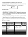
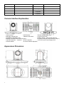
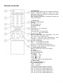
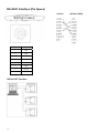
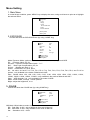
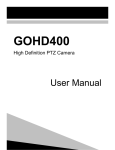
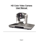
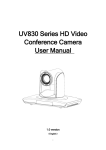
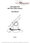
Minrray UV850
HD Color Video Camera
User Manual
English
www.Minrray.com
(800) 486-5276
0
Preface:
Thanks for using our HD color video conference camera .
This manual introduces the function installation and operation of the HD camera . Prior to
installation and usage , please read the manual thoroughly .
Warning
This product can be only used in specified range in order to avoid any damage or danger;
Don’t expose the camera to rain or moisture place
Don’t remove the cover to reduce the risk of electric shock. Refer servicing to qualified
personnel .
Never operate the camera under unqualified temperature , humidity and power supply;
Only use the replacement parts recommended by us.
Please use the soft cloth to clean the camera. Use neuter cleanser if bad smeared .No uses
the strong or cleanser avoiding scuffing.
Be careful or moving; never press the drive parts heavily avoiding camera trouble.
Notes
Electromagnetic fields at the specific frequency may affect the image quality.
1
Contents
NOTES..........................................................................................................................................................................3
SUPPLIED ACCESSORIES.........................................................................................................................................3
FAST INSTALLATION..................................................................................................................................................4
CAMERA HIGHLIGHTS ...............................................................................................................................................5
CAMERA SPECIFICATIONS .......................................................................................................................................5
CAMERA INTERFACE EXPLANATION ......................................................................................................................6
APPEARANCE DIMENSION .......................................................................................................................................6
REMOTE CONTROLLER ............................................................................................................................................7
USAGE OF IR REMOTE CONTROLLER....................................................................................................................8
RS-232C INTERFACE (PIN SPECS) .........................................................................................................................10
COM CONTROL.........................................................................................................................................................11
MENU SETTING.........................................................................................................................................................18
2
Notes
Electric Safety
Installation and operation must accord with electric safety standard
Caution to transport
Avoid stress, vibration and soakage in transport , storage and installation .
Polarity of power supply
The power supply of the product is +12V, the max electrical current is 2A .polarity of the power supply
drawing.
Careful of installation
Never move the camera by seizing the camera head . Don’t rotate camera head by hand, otherwise,
mechanical trouble will occur.
This series item must put on the smooth desk or platform , and it can not be installed slantways ;
If the camera is installed on TV or computer , the base can be fixed by three double-sided adhesive tray.
Don’t apply in corrosive liquid , gas or solid environment to avoid the cover which is made up of organic
material .
To make sure no obstacle in rotation range
Never power on before installation is not completed
Don’t dispatch discretionarily.
We are not responsible for any unauthorized modification or dismantling .
Supplied Accessories
When you unpack , check that all the supplied accessories are included :
Camera …………………………1
Power adapter …………………1
Power cable…………………….1
RS232 cable…………………….1
Remote controller………………1
User manual ……………………1
Double-side glue shim …………4
3
Fast Installation
1. Please check the connection before turn on the power .
2. Bottom Dial Switch Setting
Set Two DIP switch “OFF”,it is the Working Mode.
Setting and instruction bottom dial switch :
1
2
3
4
3
SW-1
OFF
ON
OFF
ON
SW-2
OFF
OFF
ON
ON
Modes
Working mode
Updating Mode
Debugging Mode
NONE
The Rotary Switch Setting
Sixteen Rotary Switch setting for format setting selections:
Index
0
1
2
3
4
5
6
7
8
9
A
B
C
D
E
F
1080P60
1080P50
1080I60
1080I50
720P60
720P50
1080P30
1080P25
720P30
720P25
1080P59.94
1080I59.94
720P59.94
1080P29.97
720P29.97
None
Note: Please restart the camera after shift the video format
4
4, When Power supply switch is “on” ,the indicator light is open(red color)
5, Camera initializes after 5 seconds: Rotate to the right limit, move to the down limit; Then turn left,
motor stops when horizontal and vertical rotation is in the middle, camera lens will move to the wide angel
position. Initialization finishes . (Note : the camera will move to the preset position no.0 if set )
6, Restore default setting: enter into the OSD menu by press the menu key of remote controller, select
Restore Default , moving the left/right key to press Yes
then confirm by
HOME key .
RESTORE DEFAULT
Restore?
No
Change Value
[Home] OK
[Menu] Back
Camera highlights
1 Adopts integrated 72.5°wide view angle lens 12 X optical zoom
2 provides low illumination solution, particularly suitable for occasion in the general lighting.
3 Reaches 1920×1080 pixel , the max video frame is 60/50 FPS . It definitely meets the requirement for both
high clarity and smooth picture .
4 video’s S/N ratio directly affects the HD video conference terminal’s image compression coding efficiency.
With 2D and motion-estimation based 3D noise reduction algorithm and U.S new generation low noise sensor,
the camera has effectively reduced noise;
5 The unique Iridix exposure dynamic control algorithm, based on the human eye mode, makes the image
even exposure and strong sense of hierarchy; With the most advanced CMOS sensor which support WDR ,the
camera can capture all images clearly in the strong contrast between black and light environment(such as
backlight);
6 supports DVI-I(can convert to YPbPr and HDMI output ) interface , broadcast level HD-SDI interface .
7
IR remote controller signal transparent transmission function : the camera can receive signal from both its own
remote controller and terminal equipment controller, by transmitting the signal through VISCA IN to terminal equipment
IR receiver.
Camera Specifications
Model
the camera -S
Video Format
1080p/60, 1080p/59.94, 1080p/50,
1080p/30, 1080p/29.97, 1080p/25,
1080i/60, 1080i/59.94, 1080i/50,
720p/60, 720p/59.94, 720p/50, 720p/30,
720p/29.97, 720p/25
Output Interface
Image Sensor
Image Sensor Pixel
the camera-M
1080p/30, 1080p/29.97, 1080p/25,
1080i/60, 1080i/59.94, 1080i/50,
720p/60, 720p/59.94, 720p/50,
720p/30, 720p/29.97, 720p/25
Tilt Rotation
speed
DVI-I(HDMI YPbPr)
HD-SDI optional
CMOS 1/3 inch
Up/down Installation
Pixel 274million Effective pixel
207million
Zoom
12x, f3.5mm ~ 42.3mm, F1.8 ~ F2.8
Focus
Auto Manual
Preset No.
Preset
Control Interface
Shutter Speed
1/25s ~ 1/10000s
White Balance
Auto Indoor
Outdoor
Protocol
Manual
the camera-C
WDR
B/L Compensation
Support
Power Supply
Adapter
S/N Ratio
55dB
Power Consumption
720p/60, 720p/59.94,
720p/50, 720p/30,
720p/29.97, 720p/25
1.7° ~ 69.9°/s
Support
128
0.2°
8pin Mini DIN
VISCA Pelco-D Pelco-P
100dB
DC12V/1.5A
12W
5
Pan Control Speed
72.5° ~ 6.9°/sec
Dimension
Tilt Control Speed
44.8° ~ 3.9°/sec
Color
Pan Rotation
±170°
Tilt Rotation
-30° ~ +90°
Pan Rotation Speed
1.7° ~ 100°/s
Weight
Working
Temperature
Storage
Temperature
265mmX145mmX179mm
Silver&Black
2.0Kg
0 to+45
-10
to +60
Camera Interface Explanation
1.Camera lens
2.IR Receiver
3.Power indicator light (red)
4.Standby indicator light
5.Bottom dial Switch
6.Tripod screw hole
7.Installation Orientation Hole
8.Rotary Switch : video format optional
9.RS232 controller serial interface (input )
10.RS232 controller serial interface (output )
11.HD-SDI interface optional
12.DVI-I interface
13.DC12V Input Power Supply Jack
14.Power Switch
15.Power indicator light(red)
Appearance Dimension
6
Remote Controller
0 Standby key
After pressing the standby key, the camera will step into
standby mode.Press again,the camera will open
again.(Note: Standby mode power consumption is about
half of the normal mode)
(Note: Standby mode power consumption is about half
of the normal mode)
1 Number key
Setting or locating presets
2 * key
Key combination use
3 Set preset key:
Set preset
Set preset key + 0-9 number key
Clear preset key
Clear preset key + 0-9 number key
or
+ +
clear all the presets
4 BLC control key
BLC ON open black light compensation only work
when exposure mode setting is Auto
BLC OFF
close black light compensation
Only
available in the exposure mode effective for Auto
5 Focus control key
Focus
focus length far from near
Focus
focus length near from far
Auto focus the camera focus mode is auto
Manual focus the camera focus mode is manual
6 Camera address selection
Select the camera which want to be controlled
7
# key
Key combination use
8 pan/tilt control key
Press key
up
Press key
down
Press
key
left
Press
key right
“HOME” key: Return to the middle position
9 Menu setting
Open or close the OSD menu
10 Zoom Control key
zoom
lens near
zoom
lens far
11.controlling camera address selection
* +
+ F1
Camera Address No.1
* +
+ F2
Camera Address No. 2
* +
+ F3
Camera Address No. 3
* +
+ F4
Camera Address No. 4
7
Usage of IR Remote Controller
Starting normally, the camera can receive and execute the IR commands. It can set or run preset positions,
and rotate via the IR remote controller.
Key Instruction
1 In this instruction, “press the key” means a click rather than a long-press, and a special note will be given if
a long-press for more than one second is required.
2 When a key-combination is required, do it in sequence. For example, “ * + # + F1 ”means press“ * ”first
and then press“ # ” and press“ F1 ”at last.
1.Pan/Tilt Control
Up:
press
Down: press
Left:
press
Right:
press
Back to middle position press“ HOME ”
Press and hold the up/down/left/right key, the pan/tilt will keep running, from slow to fast, until it run to the
endpoint; The pan/tilt running stops as soon as the key is released.
2. Focus Control
Focus (far) Press ” focus+ ” key
Focus (near)
Press “ focus- “key
Press and hold the key, the action of focus continues and stops as soon as the key is released.
3.Zoom Control
ZOOM OUT: press “ZOOM “ key
ZOOM IN: press “ZOOM ” key
Press and hold the key, the camera will keep zooming in or zooming out and stops as soon as the key is
released.
AUTO: auto focus
MANUAL: manual focus
8
4.BLC Setting
BLC ON / OFF: open or turn off the BLC(only available in the auto mode)
5. Presets setting
1.Preset setting : to set a preset position, the users should press the “ SET PRESET ” key first and then
press the number key 0-9 to set a relative preset.
10 preset positions in total are available via the remote controller.
2.Preset clearing : to clear a preset position, the user can press the “ CLEAR PRESET ” key first and then
press the number key 0-9 to clear the relative preset;
Note : press the“ # ” key three times continually to cancel all the presets.
6.Preset Running
Press a number key 0-9 directly to run a relative preset.
Note: Action in vain if a relative preset position is not existed.
7.Camera Selection
Select the camera address to control.
8.Camera Remote Controller Address Setting
*
*
*
*
+
+
+
+
+
+
+
+
F1
F2
F3
F4
Camera Address No.1
Camera Address No. 2
Camera Address No. 3
Camera Address No. 4
9
RS-232C Interface (Pin Specs)
Camera
No.
Function
1
DTR
2
DSR
3
TXD
4
GND
5
RXD
6
GND
7
IR OUT
8
NC
VISCA OUT Function
10
Windows DB98
COM control
In the normal working condition, the camera can connect a VISCA or Pelco-P or Pelco-D equipment via the control
of RS232 IN. The parameter of the RS232C COM is as following:
Baud Rate 2400/4800/9600 Bit/S
Start bit: 1bit ;
Data bit: 8bit ;
Stop bit : 1bit;
Code:
None
Powering on, the camera runs to the up right, then back to the middle with the farthest zoom rate in the auto
focus and the iris default value. Finishing the initialization, the camera moves to the preset no.0 if it’s saved.
Now, the camera can be controlled by the serial command.
VISCA Protocol
Part1
Camera Return Command
Ack/Completion Message
Command Packet
z0 41 FF
z0 51 FF
ACK
Completion
Note
Returned when the command is accepted.
Returned when the command has been executed.
z = Camera Address + 8
Error Messages
Command Packet
Note
Syntax Error
z0 60 02 FF
Returned when the command format is different or when a command
with illegal command parameters is accepted
Command Not Executable
z0 61 41 FF
Returned when a command cannot be executed due to current
conditions. For example, when commands controlling the focus
manually are received during auto focus.
Part 2
Controlling Command
Command
Function
Command Packet
Note
AddressSet
Broadcast
88 30 01 FF
Address setting
IF_Clear
Broadcast
88 01 00 01 FF
I/F Clear
CommandCancel
CAM_Power
CAM_Zoom
CAM_Focus
8x 21 FF
On
8x 01 04 00 02 FF
Off
8x 01 04 00 03 FF
Stop
8x 01 04 07 00 FF
Tele(Standard)
8x 01 04 07 02 FF
Wide(Standard)
8x 01 04 07 03 FF
Tele(Variable)
8x 01 04 07 2p FF
Wide(Variable)
8x 01 04 07 3p FF
Direct
8x 01 04 47 0p 0q 0r 0s FF
Stop
8x 01 04 08 00 FF
Power ON/OFF
p = 0(low) - 7(high)
pqrs: Zoom Position
Far(Standard)
8x 01 04 08 02 FF
Near(Standard)
8x 01 04 08 03 FF
Far(Variable)
8x 01 04 08 2p FF
Near(Variable)
8x 01 04 08 3p FF
Direct
8x 01 04 48 0p 0q 0r 0s FF
pqrs: Focus Position
Auto Focus
8x 01 04 38 02 FF
AF ON/OFF
Manual Focus
8x 01 04 38 03 FF
p = 0(low) - 7(high)
11
Command
Function
Auto/Manual
CAM_ZoomFocus
CAM_WB
CAM_RGain
CAM_Bgain
CAM_AE
CAM_Shutter
CAM_Iris
CAM_WDRStrength
CAM_LowLightLevel
CAM_ExpComp
Command Packet
Note
Auto
8x 01 04 38 10 FF
8x 01 04 47 0p 0q 0r 0s
0t 0u 0v 0w FF
8x 01 04 35 00 FF
pqrs: Zoom Position
tuvw: Focus Position
Normal Auto
Indoor mode
8x 01 04 35 01 FF
Indoor mode
Outdoor mode
8x 01 04 35 02 FF
Outdoor mode
Direct
OnePush mode
8x 01 04 35 03 FF
One Push WB mode
Manual
8x 01 04 35 05 FF
Manual Control mode
Temperature mode
8x 01 04 35 2p FF
p:Color Temperature
Reset
8x 01 04 03 00 FF
Up
8x 01 04 03 02 FF
Down
8x 01 04 03 03 FF
Direct
8x 01 04 43 00 00 0p 0q FF
Reset
8x 01 04 04 00 FF
Up
8x 01 04 04 02 FF
Down
8x 01 04 04 03 FF
Direct
8x 01 04 44 00 00 0p 0q FF
pq: B Gain
Full Auto
8x 01 04 39 00 FF
Automatic Exposure mode
Manual
8x 01 04 39 03 FF
Shutter priority
8x 01 04 39 0A FF
Iris priority
8x 01 04 39 0B FF
Manual Control mode
Shutter Priority Automatic Exposure
mode
Iris Priority Automatic Exposure mode
WDR
8x 01 04 39 21 FF
WDR mode
Low Light
8x 01 04 39 22 FF
Low Light mode
Reset
8x 01 04 0A 00 FF
Up
8x 01 04 0A 02 FF
Down
8x 01 04 0A 03 FF
Direct
8x 01 04 4A 00 00 0p 0q FF
Reset
8x 01 04 0B 00 FF
Up
8x 01 04 0B 02 FF
Down
8x 01 04 0B 03 FF
Direct
8x 01 04 4B 00 00 0p 0q FF
Reset
8x 01 04 21 00 FF
Up
8x 01 04 21 02 FF
Down
8x 01 04 21 03 FF
Direct
8x 01 04 51 00 00 0p 0q FF
Reset
8x 01 04 22 00 FF
Up
8x 01 04 22 02 FF
Down
8x 01 04 22 03 FF
Direct
8x 01 04 52 00 00 0p 0q FF
On
8x 01 04 3E 02 FF
Off
8x 01 04 3E 03 FF
Reset
8x 01 04 0E 00 FF
Up
8x 01 04 0E 02 FF
Down
8x 01 04 0E 03 FF
Direct
8x 01 04 4E 00 00 0p 0q FF
Manual Control of R Gain
pq: R Gain
Manual Control of B Gain
Shutter Setting
pq: Shutter Position
Iris Setting
pq: Iris Position
WDR Level Setting
pq: WDR Level Positon
Low Light Setting
pq: Low Light Position
Exposure Compensation ON/OFF
Exposure Compensation Amount Setting
pq: ExpComp Position
On
8x 01 04 33 02 FF
Off
8x 01 04 33 03 FF
CAM_NR(2D)
-
8x 01 04 53 0p FF
p: NR Setting (0: OFF, level 1 to 5)
CAM_NR(3D)
-
8x 01 04 54 0p FF
p: NR Setting (0: OFF, level 1 to 5)
CAM_BackLight
12
Back Light Compensation ON/OFF
Command
CAM_Flicker
CAM_Aperture
CAM_Memory
CAM_LR_Reverse
CAM_PictureFlip
CAM_ColorGain
CAM_ICR
Function
IR_ReceiveReturn
Pan_tiltDrive
8x 01 04 23 0p FF
Reset
8x 01 04 02 00 FF
Up
8x 01 04 02 02 FF
Down
8x 01 04 02 03 FF
Direct
8x 01 04 42 00 00 0p 0q FF
pq: Aperture Gain
Reset
8x 01 04 3F 00 0p FF
Set
8x 01 04 3F 01 0p FF
Recall
8x 01 04 3F 02 0p FF
p: Memory Number(=0 to 9)
Corresponds to 0 to 9 on the Remote
Commander.(Different with EVI-HD1)
On
8x 01 04 61 02 FF
Off
8x 01 04 61 03 FF
On
8x 01 04 66 02 FF
Off
8x 01 04 66 03 FF
Diret
8x 01 04 49 00 00 00 0p FF
ON
8x 01 04 01 02 FF
OFF
8x 01 04 01 03 FF
8x 01 04 22 0p 0q 0r 0s FF
On
8x 01 06 08 02 FF
Off
8x 01 06 08 03 FF
On/Off
8x 01 06 08 10 FF
On
8x 01 7D 01 03 00 00 FF
Off
8x 01 7D 01 13 00 00 FF
Up
8x 01 06 01 VV WW 03 01 FF
Down
8x 01 06 01 VV WW 03 02 FF
Left
8x 01 06 01 VV WW 01 03 FF
Right
8x 01 06 01 VV WW 02 03 FF
Upleft
8x 01 06 01 VV WW 01 01 FF
Upright
8x 01 06 01 VV WW 02 01 FF
DownLeft
8x 01 06 01 VV WW 01 02 FF
DownRight
8x 01 06 01 VV WW 02 02 FF
Stop
Home
8x 01 06 01 VV WW 03 03 FF
8x 01 06 02 VV WW
0Y 0Y0Y0Y 0Z 0Z0Z0Z FF
8x 01 06 03 VV WW
0Y 0Y0Y0Y 0Z 0Z0Z0Z FF
8x 01 06 04 FF
Reset
8x 01 06 05 FF
LimitSet
8x 01 06 07 00 0W
0Y 0Y0Y0Y 0Z 0Z0Z0Z FF
AbsolutePosition
RelativePosition
Aperture Control
Image Flip Horizontal ON/OFF
Image Flip Vertical ON/OFF
p: Color Gain setting 0h (60%) to Eh
(200%)
Infrared Mode ON/OFF
pqrs: Camera ID (=0000 to FFFF)
IR(remote commander)receive ON/OFF
IR(remote commander)receive message
via the VISCA communication ON/OFF
VV: Pan speed 0x01 (low speed) to 0x18
(high speed)
WW: Tilt speed 0x01 (low speed) to
0x14 (high speed)
YYYY: Pan Position(TBD)
ZZZZ: Tilt Position(TBD)
W: 1 UpRight 0: DownLeft
YYYY: Pan Limit Position
ZZZZ: Tilt Position
Pan_tiltLimitSet
CAM_AFSensitivity
Note
p: Flicker Settings(0: OFF, 1: 50Hz, 2:
60Hz)
-
CAM_IDWrite
IR_Receive
Command Packet
LimitClear
8x 01 06 07 01 0W
07 0F 0F0F 07 0F 0F0F FF
High
8x 01 04 58 01 FF
Normal
8x 01 04 58 02 FF
AF Sensitivity High/Normal/Low
Low
8x 01 04 58 03 FF
CAM_SettingReset
Reset
8x 01 04 A0 10 FF
Reset Factory Setting
CAM_Iridix
Direct
8x 01 04 A7 00 00 0p 0q FF
pq: Iridix Position
13
Command
Color System
CAM_AWBSensitivity
CAM_AFZone
CAM_DVIMode
CAM_ColorHue
Function
Command Packet
Note
RGB
8x 01 04 A8 02 FF
YPbPr
8x 01 04 A8 03 FF
High
8x 01 04 A9 00 FF
High
Normal
8x 01 04 A9 01 FF
Normal
Low`
8x 01 04 A9 02 FF
Low
Top
8x 01 04 AA 00 FF
Center
8x 01 04 AA 01 FF
Bottom
8x 01 04 AA 02 FF
HDMI
8x 01 04 AB 02 FF
DVI
8x 01 04 AB 03 FF
Direct
8x 01 04 4F 00 00 00 0p FF
CAM_Gamma
8x 01 04 5B 0p FF
Only valid in 720p60/1080p60
AF Zone weight select
DVI output mode, default: HDMI
p: Color Hue setting 0h ( 7dgrees) to Eh
( +7 degrees)
p: Gamma setting (0x00~0x0A)
Part3 Inquiry Command
Command
CAM_PowerInq
8x 09 04 00 FF
CAM_ZoomPosInq
8x 09 04 47 FF
CAM_FocusAFModeInq
8x 09 04 38 FF
CAM_FocusPosInq
8x 09 04 48 FF
CAM_WBModeInq
8x 09 04 35 FF
CAM_RGainInq
CAM_BGainInq
8x 09 04 43 FF
8x 09 04 44 FF
CAM_AEModeInq
8x 09 04 39 FF
CAM_ShutterPosInq
CAM_IrisPosInq
CAM_WDRStrengthInq
CAM_LowLightLevInq
8x 09 04 4A FF
8x 09 04 4B FF
8x 09 04 B1 FF
8x 09 04 B2 FF
CAM_ExpCompModeInq
8x 09 04 3E FF
CAM_ExpCompPosInq
8x 09 04 4E FF
CAM_BacklightModeInq
8x 09 04 33 FF
CAM_Noise2DModeInq
CAM_Noise3DModeInq
8x 09 04 53 FF
8x 09 04 54 FF
Return Packet
y0 50 02 FF
y0 50 03 FF
y0 50 0p 0q 0r 0s FF
y0 50 02 FF
y0 50 03 FF
y0 50 0p 0q 0r 0s FF
y0 50 00 FF
y0 50 01 FF
y0 50 02 FF
y0 50 03 FF
y0 50 05 FF
y0 50 2p FF
y0 50 00 00 0p 0q FF
y0 50 00 00 0p 0q FF
y0 50 00 FF
y0 50 03 FF
y0 50 0A FF
y0 50 0B FF
y0 50 21 FF
y0 50 22 FF
y0 50 00 00 0p 0q FF
y0 50 00 00 0p 0q FF
y0 50 00 00 0p 0q FF
y0 50 00 00 0p 0q FF
y0 50 02 FF
y0 50 03 FF
y0 50 00 00 0p 0q FF
y0 50 02 FF
y0 50 03 FF
y0 50 0p FF
y0 50 0p FF
CAM_FlickerModeInq
8x 09 04 55 FF
y0 50 0p FF
CAM_ApertureInq
8x 09 04 42 FF
y0 50 00 00 0p 0q FF
CAM_MemoryInq
8x 09 04 3F FF
y0 50 0p FF
SYS_MenuModeInq
8x 09 06 06 FF
CAM_LR_ReverseInq
8x 09 04 61 FF
CAM_PictureFlipInq
8x 09 04 66 FF
CAM_IDInq
8x 09 04 22 FF
14
Command Packet
y0 50 02 FF
y0 50 03 FF
y0 50 02 FF
y0 50 03 FF
y0 50 02 FF
y0 50 03 FF
y0 50 0p 0q 0r 0s FF
Note
On
Off(Standby)
pqrs: Zoom Position
Auto Focus
Manual Focus
pqrs: Focus Position
Auto
Indoor mode
Outdoor mode
OnePush mode
Manual
p:Color Temperature
pq: R Gain
pq: B Gain
Full Auto
Manual
Shutter priority
Iris priority
WDR
Low Light
pq: Shutter Position
pq: Iris Position
pq: WDR Strength
pq: Low Light Level
On
Off
pq: ExpComp Position
On
Off
Noise Reduction (2D) p: 0 to 5
Noise Reduction (3D) p: 0 to 5
p: Flicker Settings(0: OFF, 1:
50Hz, 2: 60Hz)
pq: Aperture Gain
p: Memory number last
operated.
On
Off
On
Off
On
Off
pqrs: Camera ID
Pan-tiltMaxSpeedInq
8x 09 06 11 FF
y0 50 wwzz FF
Pan-tiltPosInq
8x 09 06 12 FF
y0 50 0w 0w0w0w
0z 0z0z0z FF
ab: Factory Code(08: VHD)
cd: Hardware Version
mnpq: ARM Version
rstu: FPGA Version
vw: Socket Number
1920x1080i60
1920x1080p30
1280x720p60
1280x720p30
1920x1080p60
1920x1080i50
1920x1080p25
1280x720p50
1280x720p25
1920x1080p50
On
Off
Power ON/OFF
Zoom tele/wide
AF On/Off
CAM_Backlight
CAM_Memory
Pan_tiltDrive
ww: Pan Max Speed
zz: Tilt Max Speed
wwww: Pan Position
zzzz: Tilt Position
y0 50 01 FF
High
y0 50 02 FF
Normal
y0 50 03 FF
Low
CAM_VersionInq
8x 09 00 02 FF
VideoSystemInq
8x 09 06 23 FF
IR_Receive
8x 09 06 08 FF
IR_ReceiveReturn
CAM_AFSensitivityInq
8x 09 04 58 FF
y0 50 ab cd
mnpqrstuvw FF
y0 50 00 FF
y0 50 01 FF
y0 50 02 FF
y0 50 03 FF
y0 50 07 FF
y0 50 08 FF
y0 50 09 FF
y0 50 0A FF
y0 50 0B FF
y0 50 0F FF
y0 50 02 FF
y0 50 03 FF
y0 07 7D 01 04 00 FF
y0 07 7D 01 04 07 FF
y0 07 7D 01 04 38 FF
y0 07 7D 01 04 33 FF
y0 07 7D 01 04 3F FF
y0 07 7D 01 06 01 FF
CAM_IridixInq
8x 09 04 A7 FF
y0 50 00 00 0p 0q FF
pq: Iridix Position
Color System Inq
8x 09 04 A8 FF
y0 50 02 FF
y0 50 03 FF
CAM_GammaInq
8x 09 04 5B FF
y0 50 0p FF
VGA Mode On
VGA Mode Off
p: Gamma setting
(0x00~0x0A)
CAM_AFZone
8x 09 04 AA FF
CAM_DVIModeInq
8x 09 04 AB FF
CAM_ColorHueInq
8x 09 04 4F FF
y0 50 00 00 00 0p FF
CAM_AWBSensitivityInq
8x 09 04 A9 FF
y0 50 00 FF
y0 50 01 FF
y0 50 02 FF
y0 50 00 FF
y0 50 01 FF
y0 50 02 FF
y0 50 02 FF
y0 50 03 FF
Top
Center
Bottom
DVI Mode:HDMI
DVI Mode:DVI
p: Color Hue setting 0h (
7dgrees) to Eh ( +7 degrees)
High
Normal
Low
15
Part4 Customizing Control Command
Command
Function
CAM_Power
Command Packet
On
8x 02 16 16 16 65 FF
OFF(Standby)
8x 02 16 16 16 56 FF
TCL Standby
8x 01 02 75 75 01 04 FF
TCL Wakeup
8x 01 02 75 75 00 03 FF
Note
Custom Power ON/OFF
Forwarding
AD DA 02 B0 01 04 AF FA
Forwarding
AD DA 02 B0 00 03 AF FA
TCL_Power
Part5 Customizing Inquiry Command
Command
Command Packet
CAM_StatusInq
Note :
x
Pelco-D
8x 02 20 01 01 FF
Return Packet
y0 50 0p 00 0q rs 0t 0u FF
means the camera address you want to control ,
Note
p:Error code
q:License
rs:Video format
t:Flip mode
u:Running status
y = x+8
Protocol
Function
Byte1
Byte2
Byte3
Byte4
Byte5
Byte6
Byte7
Up
0xFF
Address
0x00
0x08
Pan Speed
Tilt Speed
SUM
Down
0xFF
Address
0x00
0x10
Pan Speed
Tilt Speed
SUM
Left
0xFF
Address
0x00
0x04
Pan Speed
Tilt Speed
SUM
Right
0xFF
Address
0x00
0x02
Pan Speed
Tilt Speed
SUM
Zoom In
0xFF
Address
0x00
0x20
0x00
0x00
SUM
Zoom Out
0xFF
Address
0x00
0x40
0x00
0x00
SUM
Focus Far
0xFF
Address
0x00
0x80
0x00
0x00
SUM
Focus Near
0xFF
Address
0x01
0x00
0x00
0x00
SUM
Set Preset
0xFF
Address
0x00
0x03
0x00
Preset ID
SUM
Clear Preset
0xFF
Address
0x00
0x05
0x00
Preset ID
SUM
Call Preset
0xFF
Address
0x00
0x07
0x00
Preset ID
SUM
Auto Focus
0xFF
Address
0x00
0x2B
0x00
0x01
SUM
Manual Focus
0xFF
Address
0x00
0x2B
0x00
0x02
SUM
Query Pan Position
Query Pan Position
Response
Query Tilt Position
Query Tilt Position
Response
Query Zoom Position
Query Zoom Position
Response
0xFF
Address
0x00
0x51
0x00
0x00
SUM
0xFF
Address
0x00
0x59
Value High Byte
Value Low Byte
SUM
0xFF
Address
0x00
0x53
0x00
0x00
SUM
0xFF
Address
0x00
0x5B
Value High Byte
Value Low Byte
SUM
0xFF
Address
0x00
0x55
0x00
0x00
SUM
0xFF
Address
0x00
0x5D
Value High Byte
Value Low Byte
SUM
16
Pelco-P Protocol
Function
Byte1
Byte2
Byte3
Byte4
Byte5
Byte6
Byte7
Byte8
Up
0xA0
Address
0x00
0x08
Pan Speed
Tilt Speed
0xAF
XOR
Down
0xA0
Address
0x00
0x10
Pan Speed
Tilt Speed
0xAF
XOR
Left
0xA0
Address
0x00
0x04
Pan Speed
Tilt Speed
0xAF
XOR
Right
0xA0
Address
0x00
0x02
Pan Speed
Tilt Speed
0xAF
XOR
Zoom In
0xA0
Address
0x00
0x20
0x00
0x00
0xAF
XOR
Zoom Out
0xA0
Address
0x00
0x40
0x00
0x00
0xAF
XOR
Focus Far
0xA0
Address
0x00
0x80
0x00
0x00
0xAF
XOR
Focus Near
0xA0
Address
0x01
0x00
0x00
0x00
0xAF
XOR
Set Preset
0xA0
Address
0x00
0x03
0x00
Preset ID
0xAF
XOR
Clear Preset
0xA0
Address
0x00
0x05
0x00
Preset ID
0xAF
XOR
Call Preset
0xA0
Address
0x00
0x07
0x00
Preset ID
0xAF
XOR
Auto Focus
0xA0
Address
0x00
0x2B
0x00
0x01
0xAF
XOR
Manual Focus
0xA0
Address
0x00
0x2B
0x00
0x02
0xAF
XOR
Query Pan Position
Query Pan Position
Response
Query Tilt Position
Query Tilt Position
Response
Query Zoom Position
Query Zoom Position
Response
0xA0
Address
0x00
0x51
0x00
0xAF
XOR
0xA0
Address
0x00
0x59
Value High Byte
0xAF
XOR
0xA0
Address
0x00
0x53
0x00
0xAF
XOR
0xA0
Address
0x00
0x5B
Value High Byte
0xAF
XOR
0xA0
Address
0x00
0x55
0x00
0xAF
XOR
0xA0
Address
0x00
0x5D
Value High Byte
0x00
Value Low
Byte
0x00
Value Low
Byte
0x00
Value Low
Byte
0xAF
XOR
17
Menu Setting
1. Main Menu
In normal image condition, press “MENU” key to display the menu, using scroll arrow to point at or highlight
the selected items.
MENU
Exposure
Color
Image
P/T/Z
Noise Reduction
Setup
Restore Default
[Home] Enter
[Menu] Exit
2. EXPOSURE
Choose and enter the EXPOSURE item (by using “HOME” key)
EXPOSURE
Mode
EV
EVLevel
BLC
G.Limit
Flicker
Meter
Auto
Off
0
Off
7
Off
Average
Select Item
Change Value
[Menu] Back
Mode: Exposure Mode, options available: Auto, Manual, AAE, SAE, Bright and WDR
EV:
Exposure Value: Off, On
EVLevel: Exposure compensation levels: -7~+7
BLC:
Back Light Compensation: Off, On
G Limit:
Biggest gain limit: 0~ +F
Flicker: Anti-Flicker: Off, 50Hz, 60Hz
Iris: Iris value, we have F1.8, F2.0, F2.4, F2.8, F3.4, F4.0, F4.8, F5.6, F6.8, F8.0, F9.6, and F11.0 for
options only available in the mode of Manual and AAE
Shut: Shutter value: 1/30, 1/60, 1/90, 1/100, 1/125, 1/180, 1/250, 1/350, 1/500, 1/725, 1/1000, 1/1500,
1/2000, 1/3000, 1/4000, 1/6000, 1/10000 only available in the mode of Manual and SAE
Stren: WDR strength: 0~6 only available in the mode of WDR
Meter : meter model , Average , Center optional .
Bright:: adjust the brightness, 00~23
3. COLOR
Choose and enter the COLOR item (by using HOME key)
BACKLIGHT
WB-Mode
Auto
Sat.
130%
AWBSens
Normal
Hue
0
Select Item
Change Value
[Menu] Back
WB-Mode: White balance mode: Auto, Indoor, Outdoor, OnePush , Manual
RG: Red Gain: 0~255 only available in the mode of Manual
BG: Blue Gain: 0~255 only available in the mode of Manual
Sat.: Saturation: 60% ~ 200%
18
AWBSens: Sensitivity of white balance. Low Normal
Hue: Tonal values of auto white balance: -7~ +7
High
4. IMAGE
Choose and enter the Image item (by using “HOME” key)
IMAGE
Brightness
Contrast
Sharpness
B&W-Mode
Flip-H
Flip-V
Gamma
0
0
12
Off
Off
Off
1.0
Select Item
Change Value
[Menu] Back
Brightness: -5 ~ +5 value setting
Contrast: -5 ~ +5 value setting
Sharpness: 0 ~ 15 value setting
B&W-Mode: On, Off
Flip-H: Image Flip Horizontal: On, Off
Flip-V: Image Flip Vertical: On, Off
Gamma: 0.5~1.5 value setting
5.P/T/Z
P/T/Z
SpeedByZ
L/R Set
AF-Zone
AF-Sense
On
STD
Center
Low
Select Item
Change Value
[Menu] Back
SpeedByZ On Off
L/R Set Remote Controller reversal setting , STD REV for setting when set REV control left and
right reversal
AF-Zone:Focus on the interested zone,Center Bottom and Top for options.
AF-Sense Sensitivity of auto focus ,Low, Normal and High for options.
6. NOISE REDUCTION
Choose and enter the Noise Reduction item (by using “HOME” key)
NOISE REDUCTION
NR2D-Level 4
NR3D-Level 3
D-HotPixel
Off
DarkDetail
5
Select Item
Change Value
[Menu] Back
NR2D-Level: 2D Noise Reduction: Off, 1 ~ 5
NR2D-Level: 3D Noise Reduction: Off, 1 ~ 5
D-HotPixel Off Auto 1 ~ 5
DarkDetail 0~15
Note: The higher the noise reduction level, the less image detail.
7. SETUP
Choose and enter the Setup item (by using “HOME” key)
19
SETUP
Language
ColorSys
DVIMode
Protocol
Address
AddrFix
Baudrate
EN
YPbPr
HDMI
VISCA
1
Off
9600
Select Item
Change Value
[Menu] Back
Language Manual Language ;EN Chinese
ColorSys Set the color system in the DVI analog signal, YPbPr RGB only under 720p60/1080p60
valid
for settings.
DVIMode Set the signal output mode of the DVI digital signal HDMI DVI undrer restart valid for
settings
Protocol VISCA, P-D, P-P
Address Set address to the protocol .In VISCA,1~7 ;
In P-D and P-P 0~15
AddrFix On Off when set On can not change camera address through Com)
Baudrate 2400 4800 9600
8. RESTORE DEFAULT
Choose and enter the RESTORE DEFAULT item (by using “HOME” key)
RESTORE DEFAULT
Restore?
No
Change Value
[Home] OK
[Menu] Back
Restore Yes No Press “HOME” key 3 seconds to restore
Note:
Restore will recover all parameters,including remote controller address and COM address.
9.EXIT
Enter the “MENU” key once again, you will see this interface.
EXIT
Save?
Change Value
[Home] OK
[Menu] Back
Save: Yes or No for options.
Note: You need to press the “HOME” key to confirm.
20
Yes