1
Electric Drives
and Controls
Hydraulics
Linear Motion and
Assembly Technologies
Pneumatics
Rexroth Frequency Converter
VFC x610 Series
VFC 3610 / VFC 5610
Operating Instructions
Service
R912005516
Edition 01
Bosch Rexroth AG
VFC x610 Series
Record of Revision
Edition
Release Date
Notes
DOK-RCON04-VFC-x610***-IT01-EN-P
2014.07
First release
Copyright
© Bosch Rexroth (Xi'an) Electric Drives and Controls Co., Ltd. 2014
This document, as well as the data, specifications and other information set
forth in it, are the exclusive property of Bosch Rexroth (Xi'an) Electric Drives
and Controls Co., Ltd. It may not be reproduced or given to third parties without its consent.
Liability
The specified data is intended for product description purposes only and shall
not be deemed to be a guaranteed characteristic unless expressly stipulated in
the contract. All rights are reserved with respect to the content of this documentation and the availability of the product.
RS-c63a6cfb1e23a43a0a6846a500ffb920-1-en-US-24
VFC x610 Series
Deutsch
Bosch Rexroth AG
English
Français
Lebensgefahr bei
Danger to life in
Nichtbeachtung der nachstehenden case of non‑compliance with the
Sicherheitshinweise!
below-mentioned safety
Nehmen Sie die Produkte erst dann instructions!
Danger de
mort en cas de non‑respect des
consignes de sécurité figurant ciaprès !
in Betrieb, nachdem Sie die mit dem
Produkt gelieferten Unterlagen und
Sicherheitshinweise vollständig
durchgelesen, verstanden und
beachtet haben.
Do not attempt to install or put these
products into operation until you
have completely read, understood
and observed the documents
supplied with the product.
Ne mettez les produits en service
qu’après avoir lu complètement et
après avoir compris et respecté les
documents et les consignes de
sécurité fournis avec le produit.
Sollten Ihnen keine Unterlagen in
Ihrer Landessprache vorliegen,
wenden Sie sich an Ihren
zuständigen RexrothVertriebspartner.
If no documents in your language
were supplied, please consult your
Rexroth sales partner.
Si vous ne disposez pas de la
documentation dans votre langue,
merci de consulter votre partenaire
Rexroth.
Only qualified persons may work
with drive components.
Seul un personnel qualifié est autorisé
à travailler sur les composants
For detailed explanations on the
safety instructions, see chapter 1 of d’entraînement.
Nähere Erläuterungen zu den
this documentation.
Vous trouverez des explications plus
Sicherheitshinweisen entnehmen
détaillées relatives aux consignes de
Sie Kapitel 1 dieser Dokumentation.
sécurité au chapitre 1 de la présente
documentation.
Nur qualifiziertes Personal darf an
Antriebskomponenten arbeiten.
Hohe elektrische
Spannung! Lebensgefahr durch
elektrischen Schlag!
High electrical
voltage! Danger to life by electric
shock!
Tensions
électriques élevées ! Danger de mort
par électrocution !
Betreiben Sie Antriebskomponenten Only operate drive components with N’exploitez les composants
nur mit fest installiertem
a permanently installed equipment d’entraînement que si un conducteur
Schutzleiter.
grounding conductor.
de protection est installé de manière
Schalten Sie vor Zugriff auf
Disconnect the power supply before permanente.
Antriebskomponenten die
Spannungsversorgung aus.
Beachten Sie die Entladezeiten von
Kondensatoren.
accessing drive components.
Observe the discharge times of the
capacitors.
Gefahrbringende
Bewegungen! Lebensgefahr!
Dangerous
movements! Danger to life!
Halten Sie sich nicht im
Bewegungsbereich von Maschinen
und Maschinenteilen auf.
Keep free and clear of the ranges of
motion of machines and moving
machine parts.
Avant d’intervenir sur les composants
d’entraînement, coupez toujours la
tension d’alimentation.
Tenez compte des délais de décharge
de condensateurs.
Mouvements entraînant une situation
dangereuse ! Danger de mort !
Ne séjournez pas dans la zone de
mouvement de machines et de
Verhindern Sie den unbeabsichtigten Prevent personnel from accidentally composants de machines.
Zutritt für Personen.
entering the range of motion of
Évitez tout accès accidentel de
machines.
personnes.
Bringen Sie vor dem Zugriff oder
Zutritt in den Gefahrenbereich die
Make sure that the drives are
Avant toute intervention ou tout accès
Antriebe sicher zum Stillstand.
brought to safe standstill before
dans la zone de danger, assurez-vous
accessing or entering the danger
de l’arrêt préalable de tous les
zone.
entraînements.
DOK-RCON04-VFC-x610***-IT01-EN-P
I
VFC x610 Series
Bosch Rexroth AG
Deutsch
Elektromagnetische / magnetische
Felder! Gesundheitsgefahr für
Personen mit Herzschrittmachern,
metallischen Implantaten oder
Hörgeräten!
English
Electromagnetic /
magnetic fields! Health hazard for
persons with heart pacemakers,
metal implants or hearing aids!
The above-mentioned persons are
not allowed to enter areas in which
Zutritt zu Bereichen, in denen
drive components are mounted and
Antriebskomponenten montiert und operated, or rather are only allowed
betrieben werden, ist für oben
to do this after they consulted a
genannten Personen untersagt bzw. doctor.
nur nach Rücksprache mit einem
Arzt erlaubt.
Français
Champs
électromagnétiques / magnétiques !
Risque pour la santé des porteurs de
stimulateurs cardiaques, d’implants
métalliques et d’appareils auditifs !
L’accès aux zones où sont montés et
exploités les composants
d’entraînement est interdit aux
personnes susmentionnées ou bien
ne leur est autorisé qu’après
consultation d’un médecin.
Heiße Oberflächen
Hot surfaces
(> 60 °C)! Verbrennungsgefahr!
(> 60 °C [140 °F])! Risk of burns!
Surfaces chaudes
(> 60 °C)! Risque de brûlure !
Vermeiden Sie das Berühren von
metallischen Oberflächen (z. B.
Kühlkörpern). Abkühlzeit der
Antriebskomponenten einhalten
(mind. 15 Minuten).
Do not touch metallic surfaces (e.g.
heat sinks). Comply with the time
required for the drive components to
cool down (at least 15 minutes).
Évitez de toucher des surfaces
métalliques (p. ex. dissipateurs
thermiques). Respectez le délai de
refroidissement des composants
d’entraînement (au moins 15
minutes).
Unsachgemäße
Handhabung bei Transport und
Montage! Verletzungsgefahr!
Improper handling
Manipulation
during transport and mounting! Risk incorrecte lors du transport et du
of injury!
montage ! Risque de blessure !
Verwenden Sie geeignete Montageund Transporteinrichtungen.
Use suitable equipment for mounting Utilisez des dispositifs de montage et
and transport.
de transport adéquats.
Benutzen Sie geeignetes Werkzeug
und persönliche Schutzausrüstung.
Use suitable tools and personal
protective equipment.
Utilisez des outils appropriés et votre
équipement de protection personnel.
Unsachgemäße
Handhabung von Batterien!
Verletzungsgefahr!
Improper handling
of batteries! Risk of injury!
Manipulation
incorrecte de piles! Risque de
blessure!
Do not attempt to reactivate or
Versuchen Sie nicht, leere Batterien recharge low batteries (risk of
zu reaktivieren oder aufzuladen
explosion and chemical burns).
(Explosions- und Verätzungsgefahr). Do not dismantle or damage
Zerlegen oder beschädigen Sie keine batteries. Do not throw batteries into
Batterien. Werfen Sie Batterien nicht open flames.
ins Feuer.
II
N’essayez pas de réactiver des piles
vides ou de les charger (risque
d’explosion et de brûlure par acide).
Ne désassemblez et n’endommagez
pas les piles. Ne jetez pas des piles
dans le feu.
DOK-RCON04-VFC-x610***-IT01-EN-P
VFC x610 Series
Español
Bosch Rexroth AG
Português
Italiano
Pericolo di
Perigo de vida em
caso de inobservância das seguintes morte in caso di inosservanza delle
seguenti indicazioni di sicurezza!
instruções de segurança!
Utilize apenas os produtos depois de Mettere in funzione i prodotti solo
Los productos no se pueden poner ter lido, compreendido e tomado em dopo aver letto, compreso e
en servicio hasta después de haber consideração a documentação e as osservato per intero la
leído por completo, comprendido y instruções de segurança fornecidas documentazione e le indicazioni di
sicurezza fornite con il prodotto.
tenido en cuenta la documentación y juntamente com o produto.
las advertencias de seguridad que se
Se non dovesse essere presente la
Se não tiver disponível a
incluyen en la entrega.
documentação na sua língua, dirija- documentazione nella vostra lingua,
siete pregati di rivolgervi al
Si no dispusiera de documentación se ao seu parceiro de venda
rivenditore Rexroth competente.
en el idioma de su país, diríjase a su responsável da Rexroth.
distribuidor competente de Rexroth.
Solo personale qualificato può
Apenas pessoal qualificado pode
eseguire lavori sui componenti di
Solo el personal debidamente
trabalhar nos componentes de
comando.
cualificado puede trabajar en
acionamento.
componentes de accionamiento.
Per ulteriori spiegazioni riguardanti le
Explicações mais detalhadas
indicazioni di sicurezza consultare il
Encontrará más detalles sobre las
relativamente às instruções de
capitolo 1 di questa documentazione.
indicaciones de seguridad en el
segurança constam no capítulo 1
capítulo 1 de esta documentación. desta documentação.
¡Peligro de
muerte en caso de no observar las
siguientes indicaciones de
seguridad!
¡Alta tensión
Alta tensão elétrica!
eléctrica! ¡Peligro de muerte por
Perigo de vida devido a choque
descarga eléctrica!
elétrico!
Active sólo los componentes de
Opere componentes de acionamento
accionamiento con el conductor
apenas com condutores de proteção
protector firmemente instalado.
instalados.
Desconecte la alimentación eléctrica Desligue a alimentação de tensão
antes de manipular los componentes antes de aceder aos componentes
de accionamiento.
de acionamento.
Tenga en cuenta los tiempos de
Respeite os períodos de descarga
descarga de los condensadores.
dos condensadores.
Alta tensione
elettrica! Pericolo di morte in seguito
a scosse elettriche!
¡Movimientos
Movimentos
peligrosos! ¡Peligro de muerte!
perigosos! Perigo de vida!
No permanezca en la zona de
Não permaneça na área de
movimiento de las máquinas ni de
movimentação das máquinas e das
sus piezas.
peças das máquinas.
Impida el acceso accidental de
Evite o acesso involuntário para
personas.
pessoas.
Antes de acceder o introducir las
Antes de entrar ou aceder à área
manos en la zona de peligro, los
perigosa, imobilize os acionamentos
accionamientos se tienen que haber de forma segura.
parado con seguridad.
Movimenti
pericolosi! Pericolo di morte!
DOK-RCON04-VFC-x610***-IT01-EN-P
Mettere in esercizio i componenti di
comando solo con conduttore di
messa a terra ben installato.
Staccare l'alimentazione prima di
intervenire sui componenti di
comando.
Osservare i tempi di scarica del
condensatore.
Non sostare nelle zone di manovra
delle macchine e delle loro parti.
Impedire un accesso non autorizzato
per le persone.
Prima di accedere alla zona di
pericolo, arrestare e bloccare gli
azionamenti.
III
VFC x610 Series
Bosch Rexroth AG
Español
Português
Italiano
¡Campos
electromagnéticos/magnéticos!
¡Peligro para la salud de las personas
con marcapasos, implantes
metálicos o audífonos!
Campos
eletromagnéticos / magnéticos!
Perigo de saúde para pessoas com
marcapassos, implantes metálicos
ou aparelhos auditivos!
Campi
elettromagnetici / magnetici! Pericolo
per la salute delle persone portatrici
di pacemaker, protesi metalliche o
apparecchi acustici!
El acceso de las personas arriba
mencionadas a las zonas de montaje
o funcionamiento de los
componentes de accionamiento está
prohibido, salvo que lo autorice
previamente un médico.
Acesso às áreas, nas quais os
componentes de acionamento são
montados e operados, é proibido
para as pessoas em cima
mencionadas ou apenas após
permissão de um médico.
L'accesso alle zone in cui sono
installati o in funzione componenti di
comando è vietato per le persone
sopra citate o consentito solo dopo un
colloquio con il medico.
¡Superficies
calientes (> 60 °C)! ¡Peligro de
quemaduras!
Superfícies quentes
Superfici bollenti
(> 60 °C)! Perigo de queimaduras! (> 60 °C)! Pericolo di ustioni!
¡Manipulación
inadecuada en el transporte y
montaje! ¡Peligro de lesiones!
Manejo incorreto no
Manipolazione
transporte e montagem! Perigo de
inappropriata durante il trasporto e il
ferimentos!
montaggio! Pericolo di lesioni!
Utilice dispositivos de montaje y de
transporte adecuados.
Utilize dispositivos de montagem e
de transporte adequados.
Utilizzare dispositivi di montaggio e
trasporto adatti.
Utilice herramientas adecuadas y
equipo de protección personal.
Utilize ferramentas e equipamento
de proteção individual adequados.
Utilizzare attrezzi adatti ed
equipaggiamento di protezione
personale.
¡Manejo
inadecuado de las pilas! ¡Peligro de
lesiones!
Manejo incorreto de
Utilizzo
baterias! Perigo de ferimentos!
inappropriato delle batterie! Pericolo
di lesioni!
Não tente reativar nem carregar
Evite tocar superfícies metálicas (p.
Evite el contacto con las superficies ex. radiadores). Respeite o tempo de
arrefecimento dos componentes de
calientes (p. ej., disipadores de
acionamento (mín. 15 minutos).
calor). Observe el tiempo de
enfriamiento de los componentes de
accionamiento (mín. 15 minutos).
Evitare il contatto con superfici
metalliche (ad es. dissipatori di
calore). Rispettare i tempi di
raffreddamento dei componenti di
comando (almeno 15 minuti).
No trate de reactivar o cargar pilas baterias vazias (perigo de explosão e
descargadas (peligro de explosión y de queimaduras com ácido).
cauterización).
Não desmonte nem danifique as
No desarme ni dañe las pilas. No tire baterias. Não deite as baterias no
fogo.
las pilas al fuego.
Non tentare di riattivare o ricaricare
batterie scariche (pericolo di
esplosione e corrosione).
IV
DOK-RCON04-VFC-x610***-IT01-EN-P
Non scomporre o danneggiare le
batterie. Non gettare le batterie nel
fuoco.
VFC x610 Series
Svenska
Bosch Rexroth AG
Dansk
Livsfara om följande
Livsfare ved
säkerhetsanvisningar inte följs!
manglende overholdelse af
nedenstående
Använd inte produkterna innan du
sikkerhedsanvisninger!
har läst och förstått den
dokumentation och de
Tag ikke produktet i brug, før du har
säkerhetsanvisningar som medföljer læst og forstået den dokumentation
produkten, och följ alla anvisningar. og de sikkerhedsanvisninger, som
Kontakta din Rexroth-återförsäljare følger med produktet, og overhold
om dokumentationen inte medföljer de givne anvisninger.
på ditt språk.
Endast kvalificerad personal får
arbeta med drivkomponenterna.
Nederlands
Levensgevaar bij niet-naleving van
onderstaande veiligheidsinstructies!
Stel de producten pas in bedrijf nadat
u de met het product geleverde
documenten en de
veiligheidsinformatie volledig gelezen,
begrepen en in acht genomen heeft.
Mocht u niet beschikken over
Kontakt din Rexroth-forhandler, hvis documenten in uw landstaal, kunt u
dokumentationen ikke medfølger på contact opnemen met uw plaatselijke
dit sprog.
Rexroth distributiepartner.
Se kapitel 1 i denna dokumentation
för närmare beskrivningar av
säkerhetsanvisningarna.
Det er kun kvalificeret personale, der Uitsluitend gekwalificeerd personeel
må arbejde på drive components.
mag aan de aandrijvingscomponenten
werken.
Nærmere forklaringer til
Hög elektrisk
spänning! Livsfara genom elchock!
Elektrisk
højspænding! Livsfare på grund af
elektrisk stød!
Använd endast drivkomponenterna
med fastmonterad skyddsledare.
sikkerhedsanvisningerne fremgår af Meer informatie over de
kapitel 1 i denne dokumentation.
veiligheidsinstructies vindt u in
hoofdstuk 1 van deze documentatie.
Drive components må kun benyttes
Koppla bort spänningsförsörjningen med et fast installeret jordstik.
före arbete på drivkomponenter.
Sørg for at koble
Var medveten om kondensatorernas spændingsforsyningen fra, inden du
rører ved drive components.
urladdningstid.
Overhold kondensatorernes
afladningstider.
Livsfara!
Farliga rörelser!
Farlige
bevægelser! Livsfare!
Uppehåll dig inte inom maskiners
och maskindelars rörelseområde.
Du må ikke opholde dig inden for
maskiners og maskindeles
Förhindra att obehöriga personer får bevægelsesradius.
tillträde.
Sørg for, at ingen personer kan få
utilsigtet adgang.
Innan du börjar arbeta eller vistas
inom drivsystemets riskområde
måste maskinen vara stillastående.
DOK-RCON04-VFC-x610***-IT01-EN-P
Stands drevene helt, inden du rører
ved drevene eller træder ind i deres
fareområde.
Hoge
elektrische spanning! Levensgevaar
door elektrische schok!
Bedien de aandrijvingscomponenten
uitsluitend met vast geïnstalleerde
aardleiding.
Schakel voor toegang tot
aandrijvingscomponenten de
spanningsvoorziening uit.
Neem de ontlaadtijden van
condensatoren in acht.
Risicovolle
bewegingen! Levensgevaar!
Houdt u niet op in het
bewegingsbereik van machines en
machineonderdelen.
Voorkom dat personen onbedoeld
toegang verkrijgen.
Voor toegang tot de gevaarlijke zone
moeten de aandrijvingen veilig tot
stilstand gebracht zijn.
V
VFC x610 Series
Bosch Rexroth AG
Svenska
Dansk
Elektromagnetiska/
magnetiska fält! Hälsofara för
Elektromagnetiske/magnetiske
personer med pacemaker, implantat felter! Sundhedsfare for personer
av metall eller hörapparat!
med pacemakere, metalliske
implantater eller høreapparater!
Det är förbjudet för ovan nämnda
Nederlands
Elektromagnetische / magnetische
velden! Gevaar voor de gezondheid
van personen met pacemakers,
metalen implantaten of
hoorapparaten!
personer (eller kräver överläggning
med läkare) att beträda områden där
drivkomponenter är monterade och i
drift.
For disse personer er der adgang
forbudt eller kun adgang med
tilladelse fra læge til de områder,
hvor drive components monteres og
drives.
Varma ytor
(> 60 °C)! Risk för brännskador!
Varme overflader
Hete
(> 60 °C)! Risiko for forbrændinger! oppervlakken (> 60 °C)!
Verbrandingsgevaar!
Undgå at berøre metaloverflader
Undvik att vidröra metallytor (t.ex.
kylelement). Var medveten om att
(f.eks. køleelementer). Overhold
det tar tid för drivkomponenterna att drive components nedkølingstid
svalna (minst 15 minuter).
(min. 15 min.).
Toegang tot gebieden, waarin
aandrijvingscomponenten worden
gemonteerd en bediend, is verboden
voor voornoemde personen of
uitsluitend toegestaan na overleg met
een arts.
Voorkom contact met metalen
oppervlakken (bijv. Koellichamen).
Afkoeltijd van de
aandrijvingscomponenten in acht
nemen (min. 15 minuten).
Felaktig
hantering vid transport och
montering! Skaderisk!
Fejlhåndtering
ved transport og montering! Risiko
for kvæstelser!
Onjuist gebruik
bij transport en montage!
Letselgevaar!
Använd passande monterings- och
transportanordningar.
Benyt egnede monterings- og
transportanordninger.
Gebruik geschikte montage- en
transportinrichtingen.
Använd lämpliga verktyg och
personlig skyddsutrustning.
Benyt egnet værktøj og personligt
sikkerhedsudstyr.
Gebruik geschikt gereedschap en een
persoonlijke veiligheidsuitrusting.
Felaktig
hantering av batterier! Skaderisk!
Fejlhåndtering af
batterier! Risiko for kvæstelser!
Onjuist gebruik
van batterijen! Letselgevaar!
Försök inte återaktivera eller ladda
upp batterier (risk för explosioner
och frätskador).
Forsøg ikke at genaktivere eller
oplade tomme batterier
(eksplosions- og ætsningsfare).
Batterierna får inte tas isär eller
skadas. Släng inte batterierna i
elden.
Undlad at skille batterier ad eller at
beskadige dem. Smid ikke batterier
ind i åben ild.
Probeer nooit lege batterijen te
reactiveren of op te laden
(explosiegevaar en gevaar voor
beschadiging van weefsel door
cauterisatie).
VI
Batterijen niet demonteren of
beschadigen. Nooit batterijen in het
vuur werpen.
DOK-RCON04-VFC-x610***-IT01-EN-P
VFC x610 Series
Suomi
Bosch Rexroth AG
Polski
Näiden
turvaohjeiden noudattamatta
jättämisestä on seurauksena
hengenvaara!
Zagrożenie
życia w razie nieprzestrzegania
poniższych wskazówek
bezpieczeństwa!
Ota tuote käyttöön vasta sen jälkeen,
kun olet lukenut läpi tuotteen
mukana toimitetut asiakirjat ja
turvallisuusohjeet, ymmärtänyt ne ja
ottanut ne huomioon.
Nie uruchamiać produktów przed
uprzednim przeczytaniem i pełnym
zrozumieniem wszystkich
dokumentów dostarczonych wraz z
produktem oraz wskazówek
bezpieczeństwa. Należy
przestrzegać wszystkich zawartych
tam zaleceń.
Jos asiakirjoja ei ole saatavana
omalla äidinkielelläsi, ota yhteys
asianomaiseen Rexrothin
myyntiedustajaan.
W przypadku braku dokumentów w
Państwa języku, prosimy o
Käyttölaitteiden komponenttien
parissa saa työskennellä ainoastaan skontaktowanie się z lokalnym
partnerem handlowym Rexroth.
valtuutettu henkilöstö.
Lisätietoa turvaohjeista löydät tämän Przy zespołach napędowych może
pracować wyłącznie
dokumentaation luvusta 1.
wykwalifikowany personel.
Český
Nebezpečí života v
případě nedodržení níže uvedených
bezpečnostních pokynů!
Před uvedením výrobků do provozu si
přečtěte kompletní dokumentaci a
bezpečnostní pokyny dodávané s
výrobkem, pochopte je a dodržujte.
Nemáte-li k dispozici podklady ve
svém jazyce, obraťte se na
příslušného obchodního partnera
Rexroth.
Na komponentách pohonu smí
pracovat pouze kvalifikovaný
personál.
Podrobnější vysvětlení k
bezpečnostním pokynům naleznete v
kapitole 1 této dokumentace.
Bliższe objaśnienia wskazówek
bezpieczeństwa znajdują się w
Rozdziale 1 niniejszej dokumentacji.
Voimakas
sähköjännite! Sähköiskun
aiheuttama hengenvaara!
Wysokie
napięcie elektryczne! Zagrożenie
życia w wyniku porażenia prądem!
Käytä käyttölaitteen komponentteja Zespoły napędu mogą być
ainoastaan maadoitusjohtimen
eksploatowane wyłącznie z
ollessa kiinteästi asennettuna.
zainstalowanym na stałe przewodem
ochronnym.
Katkaise jännitteensyöttö ennen
käyttölaitteen komponenteille
Przed uzyskaniem dostępu do
suoritettavien töiden aloittamista.
podzespołów napędu należy
odłączyć zasilanie elektryczne.
Huomioi kondensaattoreiden
purkausajat.
Zwracać uwagę na czas
rozładowania kondensatorów.
Hengenvaara!
Vaarallisia liikkeitä!
Älä oleskele koneiden tai
koneenosien liikealueella.
Niebezpieczne ruchy! Zagrożenie
życia!
Nie wolno przebywać w obszarze
pracy maszyny i jej elementów.
Pidä huolta siitä, ettei muita
henkilöitä pääse alueelle vahingossa. Nie dopuszczać osób niepowołanych
do obszaru pracy maszyny.
Pysäytä käyttölaitteet varmasti
ennen vaara-alueelle koskemista tai Przed dotknięciem urządzenia/
menemistä.
maszyny lub zbliżeniem się do
obszaru zagrożenia należy zgodnie z
zasadami bezpieczeństwa wyłączyć
napędy.
DOK-RCON04-VFC-x610***-IT01-EN-P
Vysoké elektrické
napětí! Nebezpečí života při zasažení
elektrickým proudem!
Komponenty pohonu smí být v
provozu pouze s pevně
nainstalovaným ochranným vodičem.
Než začnete zasahovat do komponent
pohonu, odpojte je od elektrického
napájení.
Dodržujte vybíjecí časy kondenzátorů.
Nebezpečné
pohyby! Nebezpečí života!
Nezdržujte se v dosahu pohybu strojů
a jejich součástí.
Zabraňte náhodnému přístupu osob.
Před zásahem nebo vstupem do
nebezpečného prostoru bezpečně
zastavte pohony.
VII
VFC x610 Series
Bosch Rexroth AG
Suomi
Sähkömagneettisia/magneettisia
kenttiä! Terveydellisten haittojen
vaara henkilöille, joilla on
sydämentahdistin, metallinen
implantti tai kuulolaite!
Polski
Pola
elektromagnetyczne / magnetyczne!
Zagrożenie zdrowia dla osób z
rozrusznikiem serca, metalowymi
implantami lub aparatami
słuchowymi!
Yllä mainituilta henkilöiltä on pääsy
kielletty alueille, joilla asennetaan tai
käytetään käyttölaitteen
komponentteja, tai heidän on ensin
saatava tähän suostumus
lääkäriltään.
Wstęp na teren, gdzie odbywa się
montaż i eksploatacja napędów jest
dla ww. osób zabroniony względnie
dozwolony po konsultacji z lekarzem.
Kuumia pintoja
(> 60 °C)! Palovammojen vaara!
Gorące
powierzchnie (> 60 °C)!
Niebezpieczeństwo poparzenia!
Vältä metallipintojen koskettamista
(esim. jäähdytyslevyt). Noudata
Unikać kontaktu z powierzchniami
käyttölaitteen komponenttien
metalowymi (np. radiatorami).
jäähtymisaikoja (väh. 15 minuuttia). Przestrzegać czasów schładzania
podzespołów napędów (min. 15
minut).
Český
Elektromagnetická/
magnetická pole! Nebezpečí pro
zdraví osob s kardiostimulátory,
kovovými implantáty nebo
naslouchadly!
Výše uvedené osoby mají zakázán
přístup do prostorů, kde jsou
montovány a používány komponenty
pohonu, resp. ho mají povolen pouze
po poradě s lékařem.
Horké povrchy
(> 60 °C)! Nebezpečí popálení!
Nedotýkejte se kovových povrchů
(např. chladicích těles). Dodržujte
dobu ochlazení komponent pohonu
(min. 15 minut).
Epäasianmukainen
käsittely kuljetuksen ja asennuksen
yhteydessä! Loukkaantumisvaara!
Niewłaściwe
Nesprávné
obchodzenie się podczas transportu zacházení při přepravě a montáži!
i montażu! Ryzyko urazu!
Nebezpečí zranění!
Käytä soveltuvia asennus- ja
kuljetuslaitteita.
Stosować odpowiednie urządzenia
montażowe i transportowe.
Používejte vhodná montážní a
dopravní zařízení.
Käytä omia työkaluja ja
henkilökohtaisia suojavarusteita.
Stosować odpowiednie narzędzia i
środki ochrony osobistej.
Používejte vhodné nářadí a osobní
ochranné vybavení.
Paristojen
epäasianmukainen käsittely!
Loukkaantumisvaara!
Niewłaściwe
Nesprávné
obchodzenie się z bateriami! Ryzyko zacházení s bateriemi! Nebezpečí
urazu!
zranění!
Älä yritä saada tyhjiä paristoja
toimimaan tai ladata niitä uudelleen
(räjähdys- ja syöpymisvaara).
Nie próbować reaktywować i nie
ładować zużytych baterii
(niebezpieczeństwo wybuchu oraz
Älä hajota paristoja osiin tai vaurioita poparzenia żrącą substancją).
niitä. Älä heitä paristoja tuleen.
Nie demontować i nie niszczyć
baterii. Nie wrzucać baterii do ognia.
Nepokoušejte se znovu aktivovat nebo
dobíjet prázdné baterie (nebezpečí
výbuchu a poleptání).
VIII
DOK-RCON04-VFC-x610***-IT01-EN-P
Nerozebírejte ani nepoškozujte
baterie. Neházejte baterie do ohně.
VFC x610 Series
Slovensko
Bosch Rexroth AG
Slovenčina
Română
Življenjska
nevarnost pri neupoštevanju
naslednjih napotkov za varnost!
Nebezpečenstvo
Pericol de
ohrozenia života pri nedodržiavaní moarte în cazul nerespectării
nasledujúcich bezpečnostných
următoarelor instrucţiuni de
siguranţă!
Izdelke začnite uporabljati šele, ko v pokynov!
celoti preberete, razumete in
Výrobky uvádzajte do prevádzky až Punerea în funcţiune a produselor
upoštevate izdelkom priloženo
potom, čo ste úplne prečítali,
trebuie efectuată după citirea,
dokumentacijo in varnostne
pochopili a zobrali do úvahy
înţelegerea şi respectarea
napotke.
podklady a bezpečnostné pokyny
documentelor şi instrucţiunilor de
dodané s výrobkom.
siguranţă, care sunt livrate împreună
Če priložena dokumentacija ni na
voljo v vašem maternem jeziku, se
Ak by ste nemali k dispozícii žiadne cu produsele.
obrnite na pristojnega distributerja
Rexroth.
podklady v jazyku svojej krajiny,
obráťte sa prosím na svojho
Samo kvalificirano osebje sme delati príslušného predajcu Rexroth.
na pogonskih komponentah.
Na komponentoch pohonu smie
Podrobnejša pojasnila o varnostnih pracovať iba kvalifikovaný personál.
navodilih najdete v poglavju 1 v tej
dokumentaciji.
În cazul în care documentele nu sunt
în limba dumneavoastră maternă, vă
rugăm să contactaţi partenerul de
vânzări Rexroth.
Numai un personal calificat poate
Bližšie vysvetlenia k bezpečnostným lucra cu componentele de acţionare.
pokynom zistite z kapitoly 1 tejto
Explicaţii detaliate privind
dokumentácie.
instrucţiunile de siguranţă găsiţi în
capitolul 1 al acestei documentaţii.
Visoka električna
Vysoké elektrické
Tensiune
napetost! Življenjska nevarnost
napätie! Nebezpečenstvo ohrozenia electrică înaltă! Pericol de moarte prin
zaradi električnega udara!
života v dôsledku zásahu elektrickým electrocutare!
Pogonske komponente uporabljajte prúdom!
Exploataţi componentele de acţionare
samo s fiksno nameščenim zaščitnim Komponenty pohonu prevádzkujte numai cu împământarea instalată
vodnikom.
iba s pevne nainštalovaným
permanent.
ochranným vodičom.
Pred dostopom do pogonske
Înainte de intervenţia asupra
komponente odklopite napajanje.
Upoštevajte čase praznjenja
kondenzatorjev.
Pred prístupom na komponenty
pohonu odpojte zdroj napätia.
Rešpektujte časy vybitia
kondenzátorov.
Nevarni premiki!
Pohyby
Življenjska nevarnost!
prinášajúce nebezpečenstvo!
Ne zadržujte se v območju delovanja Nebezpečenstvo ohrozenia života!
strojev.
Preprečite nenadzorovan dostop
oseb.
Pred prijemom ali dostopom v
nevarno območje varno zaustavite
vse gnane dele.
DOK-RCON04-VFC-x610***-IT01-EN-P
Nezdržiavajte sa v oblasti pohybu
strojov a častí strojov.
Zabráňte nepovolanému prístupu
osôb.
componentelor de acţionare,
deconectaţi alimentarea cu tensiune
electrică.
Ţineţi cont de timpii de descărcare ai
condensatorilor.
Mişcări
periculoase! Pericol de moarte!
Nu staţionaţi în zona de mişcare a
maşinilor şi a componentelor în
mişcare a maşinilor.
Împiedicaţi accesul neintenţionat al
persoanelor în zona de lucru a
maşinilor.
Pred zásahom alebo prístupom do
nebezpečnej oblasti uveďte pohony Înainte de intervenţia sau accesul în
bezpečne do zastavenia.
zona periculoasă, opriţi în siguranţă
componentele de acţionare.
IX
VFC x610 Series
Bosch Rexroth AG
Slovensko
Elektromagnetna / magnetna polja!
Nevarnost za zdravje za osebe s
spodbujevalniki srca, kovinskimi
vsadki ali slušnimi aparati!
Dostop do območij, v katerih so
nameščene delujoče pogonske
komponente, je za zgoraj navedene
osebe prepovedan oz. dovoljen
samo po posvetu z zdravnikom.
Vroče površine
(> 60 °C)! Nevarnost opeklin!
Izogibajte se stiku s kovinskimi
površinami (npr. hladilnimi telesi).
Upoštevajte čas hlajenja pogonskih
komponent (najm. 15 minut).
Slovenčina
Elektromagnetické/magnetické
polia! Nebezpečenstvo pre zdravie
osôb s kardiostimulátormi, kovovými
implantátmi alebo načúvacími
prístrojmi!
Prístup k oblastiam, v ktorých sú
namontované a prevádzkujú sa
komponenty pohonu, je pre hore
uvedené osoby zakázaný resp. je
dovolený iba po konzultácii s
lekárom.
Română
Câmpuri
electromagnetice / magnetice! Pericol
pentru sănătatea persoanelor cu
stimulatoare cardiace, implanturi
metalice sau aparate auditive!
Intrarea în zone, în care se montează
sau se exploatează componente de
acţionare, este interzisă pentru
persoanele sus numite respectiv este
permisă numai cu acordul medicului.
Horúce
Suprafeţe fierbinţi
povrchy (> 60 °C)! Nebezpečenstvo (> 60 °C)! Pericol de arsuri!
popálenia!
Nu atingeţi suprafeţele metalice (de
Zabráňte kontaktu s kovovými
ex. radiatoare de răcire). Respectaţi
povrchmi (napr. chladiacimi
timpii de răcire ai componentelor de
telesami). Dodržiavajte čas
acţionare (min. 15 minute).
vychladenia komponentov pohonu
(min. 15 minút).
Nestrokovno ravnanje
med transportom in namestitvijo!
Nevarnost poškodb!
Neodborná
manipulácia pri transporte a
montáži! Nebezpečenstvo
Uporabljajte ustrezne pripomočke za poranenia!
nameščanje in transport.
Používajte vhodné montážne a
Uporabite ustrezno orodje in osebno transportné zariadenia.
Manipulare
necorespunzătoare la transport şi
montaj! Pericol de vătămare!
Nepravilno ravnanje z
baterijami! Nevarnost poškodb!
Neodborná
manipulácia s batériami!
Nebezpečenstvo poranenia!
Manipulare
necorespunzătoare a bateriilor!
Pericol de vătămare!
Nepokúšajte sa reaktivovať alebo
nabíjať prázdne batérie
(nebezpečenstvo výbuchu a
poleptania).
Nu încercaţi să reactivaţi sau să
încărcaţi bateriile goale (pericol de
explozie şi pericol de arsuri).
zaščitno opremo.
Ne poskušajte ponovno aktivirati ali
napolniti praznih baterij (Nevarnost
zaradi eksplozij ali jedkanja).
Ne razstavljajte ali poškodujte
nobenih baterij. Baterij ne mečite v
ogenj.
X
Utilizaţi dispozitive adecvate de
montaj şi transport.
Folosiţi instrumente corespunzătoare
Používajte vhodné náradie a osobné şi echipament personal de protecţie.
ochranné prostriedky.
Nu dezasamblaţi şi nu deterioraţi
Batérie nerozoberajte ani
bateriile. Nu aruncaţi bateriile în foc.
nepoškodzujte. Nehádžte batérie do
ohňa.
DOK-RCON04-VFC-x610***-IT01-EN-P
VFC x610 Series
Magyar
Bosch Rexroth AG
Български
Latviski
Az
alábbi biztonsági útmutatások
figyelmen kívül hagyása
életveszélyes helyzethez vezethet!
Turpinājumā
Опасност за живота при
doto drošības norādījumu
неспазване на посочените по-долу neievērošana var apdraudēt dzīvību!
инструкции за безопасност!
Sāciet lietot izstrādājumu tikai pēc
Използвайте продуктите след като tam, kad esat pilnībā izlasījuši,
Üzembe helyezés előtt olvassa el,
сте се запознали подробно с
értelmezze, és vegye figyelembe a
sapratuši un ņēmuši vērā kopā ar
приложената към продукта
csomagban található
izstrādājumu piegādātos dokumentus.
документация и указания за
dokumentumban foglaltakat és a
безопасност, разбрали сте ги и сте Ja dokumenti nav pieejami Jūsu valsts
biztonsági útmutatásokat.
valodā, vērsieties pie pilnvarotā
се съобразили с тях.
Amennyiben a csomagban nem talál
Rexroth izplatītāja.
az Ön nyelvén írt dokumentumokat, Ако текстът не е написан на Вашия Darbus pie piedziņas komponentiem
език, моля обърнете се към Вашия
vegye fel a kapcsolatot az illetékes
drīkst veikt tikai kvalificēts personāls.
компетентен търговски
Rexroth-képviselővel.
представител на Rexroth.
Detalizētus paskaidrojumus attiecībā
A hajtás alkatrészein kizárólag
uz drošības norādījumiem skatiet šī
Със задвижващите компоненти
képzett személy dolgozhat.
dokumenta 1. nodaļā.
трябва да работи само
A biztonsági útmutatókkal
квалифициран персонал.
kapcsolatban további magyarázatot
Подробни пояснения към
ennek a dokumentumnak az első
инструкциите за безопасност
fejezetében találhat.
можете да видите в Глава 1 на тази
документация.
Високо
Augsts
електрическо напрежение!
elektriskais spriegums! Dzīvības
Опасност за живота от удар от
apdraudējums elektriskā trieciena dēļ!
електрически ток!
A hajtás alkatrészeit csak véglegesen
Piedziņas komponentus darbiniet tikai
Работете със задвижващите
telepített védővezetővel
ar fiksēti uzstādītu zemējumvadu.
компоненти само при здраво
üzemeltesse!
закрепен заземяващ проводник. Pirms darba pie piedziņas
Mielőtt hozzányúl a hajtás
komponentiem atslēdziet
Преди работа по задвижващите
alkatrészeihez, kapcsolja ki az
elektroapgādi.
компоненти, изключете
áramellátást.
Ņemiet vērā kondensatoru izlādes
захранващото напрежение.
Ügyeljen a kondenzátorok kisülési
laikus.
Обърнете внимание на времето за
idejére!
разреждане на кондензаторите.
Magas
elektromos feszültség! Életveszély
áramütés miatt!
Опасни
Bīstamas
движения! Опасност за живота!
kustības! Dzīvības apdraudējums!
Не стойте в обсега на движение на Neuzturieties mašīnu un mašīnas
Ne tartózkodjon a gépek és a
машините и частите на машините. detaļu kustību zonā.
gépalkatrészek mozgási területén
belül!
Не допускайте непреднамерен
Novērsiet nepiederošu personu
Illetéktelen személyeket ne engedjen достъп на хора.
piekļūšanu.
a gép közelébe!
Преди работа или влизане в
Pirms darba bīstamajās zonās pilnībā
Mielőtt beavatkozik, vagy a veszélyes опасната зона, спрете надеждно
apstādiniet piedziņu.
приводния механизъм.
zónába belép a hajtásokat
biztonságosan állítsa le.
Veszélyes mozgás! Életveszély!
DOK-RCON04-VFC-x610***-IT01-EN-P
XI
VFC x610 Series
Bosch Rexroth AG
Magyar
Elektromágneses / mágneses mező!
Káros hatással lehet a szívritmusszabályozó készülékkel,
fémbeültetéssel vagy
hallókészülékkel rendelkezők
egészségére!
Azokra a területekre, ahol hajtások
alkatrészeit szerelik és üzemeltetik, a
fent említett személyeknek tilos a
belépés, illetve csak orvosi
konzultációt követően szabad az
adott területekre lépniük.
Български
Latviski
Електромагнитни / магнитни
полета! Опасност за здравето на
хора със сърдечни стимулатори,
метални импланти или слухови
апарати!
Elektromagnētiskais / magnētiskais
lauks! Veselības apdraudējums
personām ar sirds stimulatoriem,
metāliskiem implantiem vai dzirdes
aparātiem!
Достъпът за гореспоменатите лица
до зони, в които ще се монтират и
ще работят задвижващи
компоненти се забранява, или
разрешава само след консултация
с лекар.
Tuvošanās zonām, kurās tiek montēti
un darbināti piedziņas komponenti,
iepriekš minētajām personām ir
aizliegta, respektīvi, atļauta tikai pēc
konsultēšanās ar ārstu.
Горещи
Karstas virsmas
повърхности (> 60 °C)! Опасност от (> 60 °C)! Apdedzināšanās risks!
изгаряне!
Ne érjen hozzá fémfelületekhez (pl.
Neskarieties pie metāliskām virsmām
hűtőtestekhez)! Vegye figyelembe a Не докосвайте метални
(piemēram, dzesētāja). Ļaujiet
hajtás alkatrészeinek kihűlési idejét повърхности (например
piedziņas komponentiem atdzist (min.
радиатори). Съблюдавайте
(min. 15 perc)!
15 minūtes).
времето на охлаждане на
задвижващите компоненти (мин.
15 минути).
Forró felületek
(> 60 °C)! Égésveszély!
Szakszerűtlen
kezelés szállításkor és szereléskor!
Sérülésveszély!
A megfelelő beszerelési és szállítási
eljárásokat alkalmazza!
Használjon megfelelő szerszámokat
és személyes védőfelszerelést!
Akkumulátorok
szakszerűtlen kezelése!
Sérülésveszély!
Неправилно
Nepareizi veikta
боравене по време на транспорт и transportēšana un montāža! Traumu
монтаж!Опасност от нараняване! gūšanas risks!
Използвайте подходящо монтажно Izmantojiet piemērotas montāžas un
и транспортно оборудване.
transportēšanas ierīces.
Използвайте подходящи
Izmantojiet piemērotus instrumentus
инструменти и лични предпазни
un individuālos aizsardzības līdzekļus.
средства.
Неправилно
боравене с батерии! Опасност от
нараняване!
Üres akkumulátorokat ne aktiváljon Не се опитвайте да активирате
újra, illetve ne töltsön fel (robbanás- отново или да зареждате
разредени батерии (Опасност от
és marásveszély)!
експлозия и напръскване с
Az akkumulátorokat ne szedje szét, агресивен агент).
és ne rongálja meg! Az akkumulátort
Не разглобявайте и не
ne dobja tűzbe!
повреждайте батерии. Не
хвърляйте батерии в огън.
XII
Nepareiza bateriju
lietošana! Traumu gūšanas risks!
Nemēģiniet no jauna aktivizēt vai
uzlādēt tukšas baterijas (eksploziju un
ķīmisko apdegumu draudi).
Neizjauciet un nesabojājiet baterijas.
Nemetiet baterijas ugunī.
DOK-RCON04-VFC-x610***-IT01-EN-P
VFC x610 Series
Bosch Rexroth AG
Lietuviškai
Pavojus gyvybei
nesilaikant toliau pateikiamų
saugumo nurodymų!
Naudokite gaminį tik kruopščiai
perskaitę prie jo pridėtus aprašus,
saugumo nurodymus. Susipažinkite
su jais ir vadovaukitės naudodami
gaminį.
Eesti
Ελληνικά
Alljärgnevate
Κίνδυνος
ohutusjuhiste eiramine on eluohtlik! θανάτου σε περίπτωση μη
συμμόρφωσης με τις παρακάτω οδηγίες
Võtke tooted käiku alles siis, kui
ασφαλείας!
olete toodetega kaasasolevad
materjalid ning ohutusjuhised
täielikult läbi lugenud, neist aru
saanud ja neid järginud.
Kui Teil puuduvad emakeelsed
materjalid, siis pöörduge Rexrothi
kohaliku müügiesinduse poole.
Θέστε το προϊόν σε λειτουργία αφού
διαβάσετε, κατανοήσετε και λάβετε
υπόψη το σύνολο των οδηγιών
ασφαλείας που το συνοδεύουν.
Εάν δεν υπάρχει τεκμηρίωση στη
γλώσσα σας, απευθυνθείτε σε
Ajamikomponentidega tohib töötada εξουσιοδοτημένο αντιπρόσωπο της
Rexroth.
Prie pavaros komponentų leidžiama üksnes kvalifitseeritud personal.
Μόνο εξειδικευμένο προσωπικό
dirbti tik kvalifikuotam personalui.
Täpsemaid selgitusi ohutusjuhiste
επιτρέπεται να χειρίζεται στοιχεία
kohta leiate käesoleva
Išsamesnius saugumo nurodymų
μετάδοσης κίνησης.
dokumentatsiooni peatükist 1.
paaiškinimus rasite šios
Περαιτέρω επεξηγήσεις των οδηγιών
dokumentacijos 1 skyriuje.
ασφαλείας διατίθενται στο κεφάλαιο 1
της παρούσας τεκμηρίωσης.
Jei Jūs negavote aprašo gimtąja
kalba, kreipkitės į įgaliotus Rexroth
atstovus.
Kõrge elektripinge!
Aukšta elektros
įtampa! Pavojus gyvybei dėl elektros Eluohtlik elektrilöögi tõttu!
smūgio!
Käitage ajamikomponente üksnes
püsivalt installeeritud maandusega.
Pavaros komponentus
eksploatuokite tik su fiksuotai
Lülitage enne ajamikomponentidega
instaliuotu apsauginiu laidu.
tööde alustamist toitepinge välja.
Prieš prieidami prie pavaros
Järgige kondensaatorite
komponentų išjunkite maitinimo
mahalaadumisaegu.
įtampą.
Atsižvelkite į kondensatorių
išsikrovimo trukmę.
Pavojus gyvybei!
Pavojingi judesiai!
Θέτετε σε λειτουργία τα στοιχεία
μετάδοσης κίνησης μόνο εφόσον έχει
τοποθετηθεί καλά προστατευτικός
αγωγός γείωσης.
Πριν από οποιαδήποτε παρέμβαση,
αποσυνδέστε την τροφοδοσία των
στοιχείων μετάδοσης κίνησης.
Λάβετε υπόψη τους χρόνους
αποφόρτισης των πυκνωτών.
Eluohtlik!
Ohtlikud liikumised!
Nebūkite mašinų ar jų dalių judėjimo Ärge viibige masina ja masinaosade
liikumispiirkonnas.
zonoje.
Neleiskite netyčia patekti asmenims. Tõkestage inimeste ettekavatsematu
sisenemine masina ja masinaosade
Prieš patekdami į pavojaus zoną
liikumispiirkonda.
saugiai išjunkite pavaras.
Tagage ajamite turvaline seiskamine
enne ohupiirkonda juurdepääsu või
sisenemist.
DOK-RCON04-VFC-x610***-IT01-EN-P
Υψηλή
ηλεκτρική τάση! Κίνδυνος θανάτου από
ηλεκτροπληξία!
τάσεις! Κίνδυνος θανάτου!
Επικίνδυνες
Μην στέκεστε στην περιοχή κίνησης
μηχανημάτων και εξαρτημάτων.
Αποτρέπετε την τυχαία είσοδο ατόμων.
Πριν από την παρέμβαση ή πρόσβαση
στην περιοχή κινδύνου, μεριμνήστε για
την ασφαλή ακινητοποίηση των
συστημάτων μετάδοσης κίνησης.
XIII
VFC x610 Series
Bosch Rexroth AG
Lietuviškai
Elektromagnetiniai / magnetiniai
laukai! Pavojus asmenų su širdies
stimuliatoriais, metaliniais
implantais arba klausos aparatais
sveikatai!
Prieiga prie zonų, kuriose
montuojami ir eksploatuojami
pavaros komponentai, aukščiau
nurodytiems asmenims yra
draudžiama arba leistina tik
pasitarus su gydytoju.
Karšti
paviršiai (> 60 °C)! Nudegimo
pavojus!
Venkite liesti metalinius paviršius
(pvz., radiatorių). Išlaikykite pavaros
komponentų atvėsimo trukmę (bent
15 minučių).
Netinkamas
darbas transportuojant ir
montuojant! Susižalojimo pavojus!
Naudokite tinkamus montavimo ir
transportavimo įrenginius.
Eesti
Elektromagnetilised /
magnetilised väljad! Terviseohtlik
südamestimulaatorite,
metallimplantaatide ja
kuulmisseadmetega inimestele!
Ελληνικά
Ηλεκτρομαγνητικά/μαγνητικά πεδία!
Κίνδυνος για την υγεία ατόμων με
καρδιακούς βηματοδότες, μεταλλικά
εμφυτεύματα ή συσκευές ακοής!
Sisenemine piirkondadesse, kus
toimub ajamikomponentide
monteerimine ja käitamine, on
ülalnimetatud isikutele keelatud või
lubatud üksnes pärast arstiga
konsulteerimist.
Η είσοδος σε περιοχές όπου
πραγματοποιείται συναρμολόγηση και
λειτουργία στοιχείων μετάδοσης
κίνησης απαγορεύεται στα
προαναφερθέντα άτομα, εκτός αν τους
έχει δοθεί σχετική άδεια κατόπιν
συνεννόησης με γιατρό.
Kuumad
välispinnad (> 60 °C)! Põletusoht!
Καυτές επιφάνειες
(> 60 °C)! Κίνδυνος εγκαύματος!
Vältige metalsete välispindade (nt
radiaatorid) puudutamist. Pidage
kinni ajamikomponentide
mahajahtumisajast (vähemalt 15
minutit).
Αποφεύγετε την επαφή με μεταλλικές
επιφάνειες (π.χ. μονάδες ψύξης).
Λάβετε υπόψη το χρόνο ψύξης των
στοιχείων μετάδοσης κίνησης
(τουλάχιστον 15 λεπτά).
Asjatundmatu
Ακατάλληλος
käsitsemine transportimisel ja
χειρισμός κατά τη μεταφορά και
montaažil! Vigastusoht!
συναρμολόγηση! Κίνδυνος
τραυματισμού!
Kasutage sobivaid montaaži- ja
Naudokite tinkamus įrankius ir
asmens saugos priemones.
transpordiseadiseid.
Kasutage sobivaid tööriistu ja
isiklikku kaitsevarustust.
Χρησιμοποιείτε κατάλληλους
μηχανισμούς συναρμολόγησης και
μεταφοράς.
Netinkamas
darbas su baterijomis! Susižalojimo
pavojus!
Patareide
asjatundmatu käsitsemine!
Vigastusoht!
Ακατάλληλος
χειρισμός μπαταριών! Κίνδυνος
τραυματισμού!
Χρησιμοποιείτε κατάλληλα εργαλεία
και ατομικό εξοπλισμό προστασίας.
Ärge üritage kunagi tühje patareisid
Nebandykite tuščių baterijų
reaktyvuoti arba įkrauti (sprogimo ir reaktiveerida või täis laadida
(plahvatus- ja söövitusoht).
išėsdinimo pavojus).
Neardykite ir nepažeiskite baterijų. Ärge demonteerige ega kahjustage
patareisid. Ärge visake patareisid
Nemeskite baterijų į ugnį.
tulle.
Μην επιδιώκετε να ενεργοποιήσετε
ξανά ή να φορτίσετε κενές μπαταρίες
(κίνδυνος έκρηξης και διάβρωσης).
XIV
DOK-RCON04-VFC-x610***-IT01-EN-P
Μην διαλύετε ή καταστρέφετε τις
μπαταρίες. Μην απορρίπτετε τις
μπαταρίες στη φωτιά.
VFC x610 Series
Bosch Rexroth AG
中文
如果不按照下述指定的安全说明使用,将会导致人身伤害!
在没有阅读,理解随本产品附带的文件并熟知正当使用前,不要安装或使用本产品。
如果没有您所在国家官方语言文件说明,请与 Rexroth 销售伙伴联系。
只允许有资格人员对驱动器部件进行操作。
安全说明的详细解释在本文档的第一章。
高电压!电击导致生命危险!
只有在安装了永久良好的设备接地导线后才可以对驱动器的部件进行操作。
在接触驱动器部件前先将驱动器部件断电。
确保电容放电时间。
危险运动!生命危险!
保证设备的运动区域内和移动部件周围无障碍物。
防止人员意外进入设备运动区域内。
在接近或进入危险区域之前,确保传动设备安全停止。
电磁场/磁场!对佩戴心脏起搏器、金属植入物和助听器的人员会造成严重的人身伤害 !
上述人员禁止进入安装及运行的驱动器区域,或者必须事先咨询医生。
热表面(大于 60 度)!灼伤风险!
不要触摸金属表面(例如散热器)。驱动器部件断电后需要时间进行冷却(至少 15 分钟)。
安装和运输不当导致受伤危险!当心受伤!
使用适当的运输和安装设备。
使用适合的工具及用适当的防护设备。
电池操作不当!受伤风险!
请勿对低电量电池重新激活或重新充电(爆炸和腐蚀的危险)。
请勿拆解或损坏电池。请勿将电池投入明火中。
DOK-RCON04-VFC-x610***-IT01-EN-P
XV
Bosch Rexroth AG
XVI
VFC x610 Series
DOK-RCON04-VFC-x610***-IT01-EN-P
VFC x610 Series
Bosch Rexroth AG
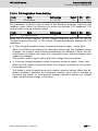
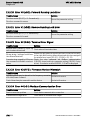
Table of Contents
Table of Contents
Page
1
1.1
1.2
1.3
1.3.1
1.3.2
1.3.3
1.4
1.4.1
1.4.2
1.4.5
1.4.6
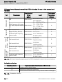
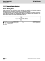
Safety Instructions for Electric Drives and Controls.............................. 1
Definitions of Terms.............................................................................. 1
Explanation of Signal Words and the Safety Alert Symbol.................... 3
General Information............................................................................... 4
Using the Safety Instructions and Passing Them on to Others.............. 4
Requirements for Safe Use.................................................................... 4
Hazards by Improper Use....................................................................... 6
Instructions with Regard to Specific Dangers....................................... 7
Protection Against Contact With Electrical Parts and Housings............ 7
Protective Extra-Low Voltage as Protection Against Electric
Shock .................................................................................................... 8
Protection Against Dangerous Movements............................................ 8
Protection Against Magnetic and Electromagnetic Fields During Operation and Mounting........................................................................... 10
Protection Against Contact with Hot Parts.......................................... 11
Protection During Handling and Mounting.......................................... 11
2
2.1
2.2
Important Directions for Use............................................................... 12
Appropriate Use................................................................................... 12
Inappropriate Use................................................................................ 12
3
3.1
3.2
Documentation Information................................................................. 13
About this Documentation................................................................... 13
Reference............................................................................................. 13
4
4.1
4.1.1
4.1.2
4.2
4.3
4.4
4.5
Delivery and Storage............................................................................
Product Identification..........................................................................
Packing Nameplate..............................................................................
Product Nameplate..............................................................................
Visual Inspection..................................................................................
Scope of Supply...................................................................................
Transport of the Components.............................................................
Storage of the Components.................................................................
5
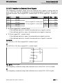
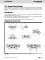
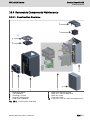
Drive System Overview........................................................................ 17
6
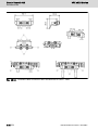
Frequency Converter Overview............................................................ 18
1.4.3
1.4.4
DOK-RCON04-VFC-x610***-IT01-EN-P
14
14
14
15
15
15
16
16
XVII
Bosch Rexroth AG
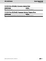
Table of Contents
VFC x610 Series
Page
6.1
6.1.1
6.1.2
6.1.3
6.1.4
6.1.5
6.1.6
6.1.7
6.1.8
6.1.9
6.2
6.2.1
6.2.2
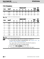
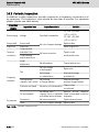
Product Features.................................................................................
Input....................................................................................................
Output.................................................................................................
V/f Control Performance......................................................................
SVC Control Performance....................................................................
Main Functions....................................................................................
Communication....................................................................................
Operating Panel...................................................................................
Protection............................................................................................
Conditions...........................................................................................
Technical Data.....................................................................................
Electric Data........................................................................................
Derating of Electric Data......................................................................
Derating and ambient temperature.....................................................
Derating and mains voltage.................................................................
Derating and carrier frequency............................................................
18
18
18
18
18
19
19
20
20
20
21
21
22
22
23
24
7
7.1
7.2
7.3
7.3.1
7.3.2
7.3.3
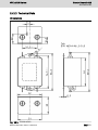
Frequency Converter Mounting...........................................................
Installation Conditions.........................................................................
Heat Dissipation..................................................................................
Figures and Dimensions.......................................................................
Figures.................................................................................................
Dimensions..........................................................................................
DIN Rail Mounting................................................................................
25
25
26
27
27
28
29
8
8.1
8.2
8.2.1
8.2.2
8.3
8.3.1
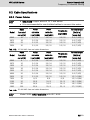
Frequency Converter Wiring................................................................
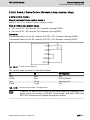
Wiring Diagram....................................................................................
Cable Specifications............................................................................
Power Cables.......................................................................................
Control Cables.....................................................................................
Terminals.............................................................................................
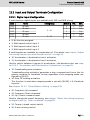
Power Terminals..................................................................................
Power Terminals Figure.......................................................................
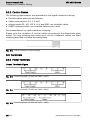
Power Terminals Description...............................................................
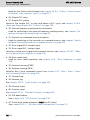
Control Terminals................................................................................
Control terminals figure.......................................................................
Control terminals description..............................................................
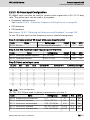
Digital input X1...X5 NPN / PNP wiring................................................
Digital output DO1a, DO1b load pull-up / pull-down wiring................
30
30
31
31
32
32
32
32
33
34
34
35
37
38
8.3.2
XVIII
DOK-RCON04-VFC-x610***-IT01-EN-P
VFC x610 Series
Bosch Rexroth AG
Table of Contents
Page
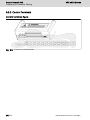
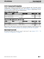
Analog input terminals (AI1, AI2, +10 V, +5 V, Earth and GND)........... 38
9
9.1
9.1.1
Electromagnetic Compatibility (EMC).................................................
EMC Requirements..............................................................................
General Information.............................................................................
The electromagnetic compatibility (EMC) or electromagnetic interference (EMI) includes the following requirements:............................
Noise Immunity in the Drive System....................................................
Basic structure for noise immunity......................................................
Minimum immunity requirements for PDSs intended for use in the
second environment............................................................................
Evaluation criterion..............................................................................
Noise Emission of the Drive System....................................................
Ensuring the EMC Requirements.........................................................
EMC Measures for Design and Installation..........................................
Rules for Design of Installations with Drive Controllers in Compliance with EMC.....................................................................................
EMC-optimal Installation in Facility and Control Cabinet....................
Control Cabinet Mounting according to Interference Areas – Exemplary Arrangements..............................................................................
Design and Installation in Area A – Interference-free Area of Control
Cabinet................................................................................................
Design and Installation in Area B – Interference-susceptible Area of
Control Cabinet...................................................................................
Design and Installation in Area C – Strongly Interference-susceptible
Area of Control Cabinet.......................................................................
Ground Connections............................................................................
Installing Signal Lines and Signal Cables.............................................
General Measures of Radio Interference Suppression for Relays,
Contactors, Switches, Chokes and Inductive Loads............................
39
39
39
10
10.1
10.2
10.3
10.4
10.5
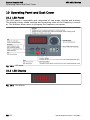
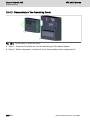
Operating Panel and Dust Cover.........................................................
LED Panel............................................................................................
LED Display..........................................................................................
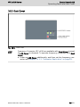
Dust Cover...........................................................................................
LED Indicator.......................................................................................
Operating Descriptions........................................................................
58
58
58
59
60
61
11
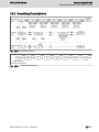
11.1
Quick Start........................................................................................... 62
Checklist before Quick Start............................................................... 62
9.1.2
9.1.3
9.2
9.3
9.3.1
9.3.2
9.3.3
9.3.4
9.3.5
9.3.6
9.3.7
9.3.8
9.3.9
DOK-RCON04-VFC-x610***-IT01-EN-P
39
39
39
40
40
41
45
47
47
49
50
51
53
54
55
56
57
XIX
Bosch Rexroth AG
Table of Contents
VFC x610 Series
Page
11.1.1
11.1.2
11.1.3
11.2
11.3
11.4
11.5
11.6
Step 1: Check application conditions..................................................
Step 2: Check mounting conditions.....................................................
Step 3: Check the wiring.....................................................................
Quick Start Parameters.......................................................................
Control the Motor................................................................................
Motor Parameters Auto-Tuning............................................................
Possible Errors during Quick Start and Respective Solutions.............
Restoring Parameters to Factory Defaults...........................................
62
62
62
63
64
65
66
66
12
12.1
12.1.1
12.1.2
12.1.3
12.1.4
12.2
12.2.1
12.2.2
12.2.3
12.2.4
12.2.5
12.3
12.3.1
12.3.2
12.3.3
12.3.4
12.4
12.4.1
12.4.2
Functions and Parameters...................................................................
Basic Settings......................................................................................
Parameter Group Access Control........................................................
Parameter Initialization........................................................................
Parameter Replication.........................................................................
Password Protection...........................................................................
Input and Output Terminals Configuration..........................................
Digital Input Configuration..................................................................
X5 Pulse Input Configuration...............................................................
Analog Input Configuration..................................................................
Digital Output Configuration...............................................................
Analog Output Configuration...............................................................
Power Stage Configuration..................................................................
Set the Control Mode..........................................................................
Normal / Heavy Duty Setting................................................................
Carrier Frequency Setting....................................................................
Fan Maintenance Reminder.................................................................
Basic Frequency Setting Sources........................................................
Function Description...........................................................................
Select the Frequency Setting Source..................................................
General setting....................................................................................
Frequency setting source switching....................................................
Frequency setting sources combination..............................................
Adjust the setting frequency by panel potentiometer.........................
Adjust the setting frequency by panel button......................................
Adjust the setting frequency by analog input AI1, AI2.........................
Adjust the setting frequency by X5 pulse input...................................
Adjust the setting frequency by digital input Up / Down command....
Adjust the setting frequency by multi-speed function.........................
67
67
67
68
69
70
71
71
73
75
76
78
80
80
80
81
82
83
83
84
84
85
86
87
87
88
88
89
91
XX
DOK-RCON04-VFC-x610***-IT01-EN-P
VFC x610 Series
Bosch Rexroth AG
Table of Contents
Page
12.4.3 Acceleration and Deceleration Configuration...................................... 95
Acceleration and deceleration time configuration............................... 95
Acceleration and deceleration curve mode configuration................... 96
12.4.4 Output Frequency Limitation............................................................... 98
Direct output frequency limitation...................................................... 98
Behavior at low speed running............................................................ 98
12.4.5 Frequency Setting Saving.................................................................. 100
12.5
Run- / Stop- / Direction Command Source........................................ 101
12.5.1 Function Description......................................................................... 101
12.5.2 Run Command Source....................................................................... 102
First and second run command source configuration....................... 102
Switch between first and second run command source................... 102
Stop command via panel <Stop> button........................................... 102
12.5.3 Direction Control............................................................................... 103
Direction control via operation panel................................................ 103
Direction change dead time............................................................... 104
12.5.4 Start Behavior Setting....................................................................... 105
Start mode selection......................................................................... 105
Start directly...................................................................................... 105
DC-braking before start..................................................................... 106
Start with speed capture................................................................... 107
12.5.5 Stop Behavior Setting........................................................................ 108
Stop mode setting............................................................................. 108
DC-braking during deceleration to stop............................................. 109
Overexcitation braking....................................................................... 110
12.5.6 Resistor Braking................................................................................. 111
12.6
Special Running Behaviors................................................................ 113
12.6.1 Skip Frequency.................................................................................. 113
12.6.2 Jog Function...................................................................................... 115
12.6.3 2-wire / 3-wire Control (Forward / stop, reverse / stop)................... 117
2-wire control mode 1....................................................................... 117
2-wire control mode 2 (Forward / reverse, run / stop)..................... 118
3-wire control.................................................................................... 119
12.7
Special Functions.............................................................................. 121
12.7.1 Counter Function............................................................................... 121
12.7.2 Frequency Arrival............................................................................... 123
12.7.3 Frequency Level Detection................................................................ 124
12.7.4 High Resolution Current Display........................................................ 125
DOK-RCON04-VFC-x610***-IT01-EN-P
XXI
Bosch Rexroth AG
Table of Contents
VFC x610 Series
Page
12.8
Simple PLC........................................................................................
12.8.1 Function Description.........................................................................
12.8.2 Set the Simple PLC Mode..................................................................
12.8.3 Set Speed / Direction / Acceleration and Deceleration Time............
12.8.4 Stop and Pause Simple PLC Control.................................................
12.8.5 Indication of Simple PLC Status........................................................
12.9
PID Control........................................................................................
12.9.1 Function Description.........................................................................
12.9.2 Selecting the Reference and Feedback.............................................
12.9.3 Control Loop Configuration...............................................................
12.9.4 PID Regulation Mode Setting.............................................................
12.9.5 PID Deactivation by Digital Input.......................................................
12.9.6 PID Engineering Value Display...........................................................
12.9.7 PID Status Indication.........................................................................
12.9.8 Sleep / Wake Function.......................................................................
12.10 Protection Functions.........................................................................
12.10.1 Converter Protection.........................................................................
Overload pre-warning........................................................................
Stall overvoltage prevention..............................................................
Stall overcurrent prevention..............................................................
Phase loss protection........................................................................
12.10.2 Reaction to External Error Signals.....................................................
12.10.3 Motor Protection...............................................................................
Motor derating frequency at low speed.............................................
Motor thermal protection without temperature sensor.....................
Motor overload pre-warning..............................................................
Motor thermal protection with temperature sensor..........................
12.10.4 Resistor Braking Test.........................................................................
12.11 Motor Control....................................................................................
12.11.1 Motor Parameterization.....................................................................
Nameplate parameters configuration................................................
Motor slip frequency configuration....................................................
Motor parameter auto-tuning.............................................................
12.11.2 VFC 3610 - V/f Control.......................................................................
V/f curve selection.............................................................................
User-defined V/f curve configuration.................................................
Slip compensation factor configuration.............................................
Torque boost setting.........................................................................
XXII
126
126
127
128
129
130
132
132
133
134
135
136
136
137
138
140
140
140
141
142
144
145
146
146
147
147
148
150
151
151
151
152
153
155
155
156
158
159
DOK-RCON04-VFC-x610***-IT01-EN-P
VFC x610 Series
Bosch Rexroth AG
Table of Contents
Page
Optimization functions for V/f control...............................................
12.11.3 VFC 5610 - SVC Control.....................................................................
SVC control loop configuration..........................................................
Speed control mode..........................................................................
Torque control mode.........................................................................
162
164
164
164
165
13
Diagnosis...........................................................................................
13.1
Status Code.......................................................................................
13.2
Warning Code....................................................................................
13.3
Error Code.........................................................................................
13.3.1 Error 1 (OC-1): Overcurrent at Constant Speed................................
13.3.2 Error 2 (OC-2): Overcurrent during Acceleration...............................
13.3.3 Error 3 (OC-3): Overcurrent during Deceleration..............................
13.3.4 Error 4 (OE-1): Overvoltage at Constant Speed................................
13.3.5 Error 5 (OE-2): Overvoltage during Acceleration...............................
13.3.6 Error 6 (OE-3): Overvoltage during Deceleration...............................
13.3.7 Error 7 (OE-4): Overvoltage during Stop...........................................
13.3.8 Error 8 (UE-1): Undervoltage during Run...........................................
13.3.9 Error 9 (SC): Current Surge or Short Circuit.....................................
13.3.10 Error 10 (IPH.L): Input Phase Loss....................................................
13.3.11 Error 11 (OPH.L): Output Phase Loss...............................................
13.3.12 Error 12 (ESS-): Soft Start Error........................................................
13.3.13 Error 20 (OL-1): Converter Overload.................................................
13.3.14 Error 21 (OH): Converter over Temperature......................................
13.3.15 Error 22 (UH): Converter under Temperature....................................
13.3.16 Error 23 (FF): Fan Failure..................................................................
13.3.17 Error 30 (OL-2): Motor Overload.......................................................
13.3.18 Error 31 (Ot): Motor over Temperature.............................................
13.3.19 Error 32 (t-Er): Motor Parameter Tuning Error..................................
13.3.20 Error 40 (dir1): Forward Running Lock Error....................................
13.3.21 Error 41 (dir2): Reverse Running Lock Error.....................................
13.3.22 Error 42 (E-St): Terminal Error Signal................................................
13.3.23 Error 43 (FFE-): Firmware Version Mismatch.....................................
13.3.24 Error 44 (rS-): Modbus Communication Error...................................
13.3.25 Error 50 (idE-): Converter Internal Error............................................
13.3.26 Error 55 (PbrE): Parameter Backup / Restore Error..........................
13.4
Error Handling....................................................................................
13.4.1 Restarting after Power Loss..............................................................
169
169
169
170
170
170
171
171
171
172
172
172
172
173
173
173
174
174
174
174
175
175
175
176
176
176
176
176
177
177
178
178
DOK-RCON04-VFC-x610***-IT01-EN-P
XXIII
Bosch Rexroth AG
Table of Contents
VFC x610 Series
Page
13.4.2 Automatic Error Reset....................................................................... 179
13.4.3 Error Reset by X1…X5 Digital Input................................................... 180
14
14.1
14.2
14.2.1
14.2.2
14.2.3
14.2.4
14.2.5
14.3
14.3.1
14.3.2
14.3.3
14.3.4
14.3.5
14.3.6
14.3.7
15
15.1
15.2
15.2.1
15.2.2
XXIV
Communication..................................................................................
Brief Introduction..............................................................................
Basic Communication Settings..........................................................
Selection of the Communication Protocol.........................................
Setting the Data Transmission Rate..................................................
Setting the Data Format....................................................................
Setting the Local Address..................................................................
Communication Disruption and Response........................................
Modbus Protocol...............................................................................
Protocol Description..........................................................................
Brief introduction..............................................................................
Transmission......................................................................................
Modbus Interface...............................................................................
Modbus Function and Message Format.............................................
Supported functions..........................................................................
Function example..............................................................................
Function 0x06: Write one register word............................................
Function 0x08: Diagnostics................................................................
Function 0x10: Write N register words, range: 1...16........................
Function 0x17: Read/Write N register words, range: 1...16...............
Error code and exception code.........................................................
Communication Mapping Register Address Distribution...................
Frequency converter parameter registers..........................................
Communication control registers......................................................
Communication state feedback registers (0x7FA0)...........................
Modbus Communication Example.....................................................
Special Notes.....................................................................................
Communication Networking..............................................................
Networking........................................................................................
Recommendations on networking.....................................................
181
181
181
181
181
182
182
182
183
183
183
184
185
185
185
187
188
189
190
190
192
193
193
194
195
196
197
198
198
198
Accessories........................................................................................
Optional Accessories.........................................................................
External EMC Filter............................................................................
External EMC Filter Type...................................................................
Technical Data...................................................................................
199
199
200
200
201
DOK-RCON04-VFC-x610***-IT01-EN-P
VFC x610 Series
Bosch Rexroth AG
Table of Contents
Page
15.6
Dimensions........................................................................................
Electric data.......................................................................................
External Brake Resistor.....................................................................
Braking Ratio.....................................................................................
Brake Resistor Selection for Braking Ratio of 10 %...........................
Brake Resistor Selection for Braking Ratio of 20 %...........................
Shielded Cable Connector.................................................................
Panel Mounting Plate.........................................................................
Function Description.........................................................................
Recommended Opening Dimensions at Control Cabinet..................
Mounting the Plate and the Operating Panel.....................................
Step 1................................................................................................
Step 2................................................................................................
Step 3................................................................................................
Step 4................................................................................................
Communication Cable for Control Cabinet........................................
201
206
208
208
209
210
211
213
213
213
214
214
214
215
215
216
16
16.1
16.2
16.3
16.4
16.4.1
16.4.2
16.4.3
Maintenance......................................................................................
Safety Instructions.............................................................................
Daily Inspection.................................................................................
Periodic Inspection............................................................................
Removable Components Maintenance..............................................
Construction Overview......................................................................
Disassembly of the Operating Panel..................................................
Disassembly of Fans..........................................................................
217
217
217
218
219
219
220
221
17
Service and Support.......................................................................... 222
18
18.1
18.2
Environmental Protection and Disposal ............................................ 223
Environmental Protection.................................................................. 223
Disposal............................................................................................. 223
19
19.1
19.2
19.2.1
19.2.2
19.2.3
19.2.4
Appendix............................................................................................
Appendix I: Abbreviations..................................................................
Appendix II: Type Coding...................................................................
Frequency Converter Type Coding....................................................
Operating Panel Type Coding............................................................
External EMC Filter Type Coding.......................................................
Panel Mounting Plate Type Coding....................................................
15.3
15.3.1
15.3.2
15.3.3
15.4
15.5
15.5.1
15.5.2
15.5.3
DOK-RCON04-VFC-x610***-IT01-EN-P
225
225
226
226
227
228
229
XXV
Bosch Rexroth AG
Table of Contents
VFC x610 Series
Page
19.2.5
19.2.6
19.3
19.3.1
19.3.2
19.3.3
19.3.4
19.3.5
19.3.6
19.4
19.4.1
Communication Cable for Control Cabinet Type Coding...................
Engineering Software Type Coding....................................................
Appendix III: Parameter List..............................................................
Terminology and Abbreviation in Parameter List...............................
Group b: System Parameters.............................................................
b0: Basic system parameters.............................................................
Group C: Power Parameters..............................................................
C0: Power control parameters...........................................................
C1: Motor and system parameters....................................................
C2: V/f control parameters................................................................
C3: Vector control parameters..........................................................
Group E: Function Control Parameters..............................................
E0: Set point and control parameters................................................
E1: Input terminal parameters...........................................................
E2: Output terminal parameters........................................................
E3: Multi-speed and simple PLC parameters.....................................
E4: PID control parameters...............................................................
E5: Extended function parameters....................................................
E8: Standard communication parameters.........................................
E9: Protection and error parameters.................................................
Group U: Panel Parameters...............................................................
U0: General panel parameters...........................................................
U1: Seven-segment panel parameters...............................................
Group d0: Monitoring Parameters.....................................................
Appendix IV: Certification..................................................................
CE......................................................................................................
229
230
231
231
231
231
232
232
234
235
236
237
237
240
242
244
245
246
246
247
249
249
249
250
251
251
Index.................................................................................................. 253
XXVI
DOK-RCON04-VFC-x610***-IT01-EN-P
VFC x610 Series
Bosch Rexroth AG
Safety Instructions for Electric Drives and Controls
1 Safety Instructions for Electric Drives and Controls
1.1 Definitions of Terms
Documentation
A documentation comprises the entire documentation used to inform the user of
the product about the use and safety-relevant features for configuring, integrating, mounting, installing, commissioning, operating, maintaining, repairing and
decommissioning the product. The following terms are also used for this kind of
documentation: Operating Instructions, Instruction Manual, Commissioning
Manual, Application Description, Assembly Instructions, Project Planning Manual, Safety Notes, Product Insert, etc.
Component
A component is a combination of elements with a specified function, which are
part of a piece of equipment, device or system. Components of the electric drive
and control system are, for example, supply units, drive controllers, mains
choke, mains filter, motors, cables, etc.
Control System
A control system comprises several interconnected control components placed
on the market as a single functional unit.
Device
A device is a finished product with a defined function, intended for users and
placed on the market as an individual piece of merchandise.
Electrical Equipment
Electrical equipment encompasses all devices used to generate, convert, transmit, distribute or apply electrical energy, such as electric motors, transformers,
switching devices, cables, lines, power-consuming devices, circuit board assemblies, plug-in units, control cabinets, etc.
Electric Drive System
An electric drive system comprises all components from mains supply to motor
shaft; this includes, for example, electric motor(s), motor encoder(s), supply
units and drive controllers, as well as auxiliary and additional components, such
as mains filter, mains choke and the corresponding lines and cables.
Installation
An installation consists of several devices or systems interconnected for a defined purpose and on a defined site which, however, are not intended to be
placed on the market as a single functional unit.
Machine
A machine is the entirety of interconnected parts or units at least one of which
is movable. Thus, a machine consists of the appropriate machine drive eleDOK-RCON04-VFC-x610***-IT01-EN-P
1/259
Bosch Rexroth AG
Safety Instructions for Electric Drives and Controls
VFC x610 Series
ments, as well as control and power circuits, which have been assembled for a
specific application. A machine is, for example, intended for processing, treatment, movement or packaging of a material. The term "machine" also covers a
combination of machines which are arranged and controlled in such a way that
they function as a unified whole.
Manufacturer
The manufacturer is an individual or legal entity bearing responsibility for the
design and manufacture of a product which is placed on the market in the individual's or legal entity's name. The manufacturer can use finished products, finished parts or finished elements, or contract out work to subcontractors. However, the manufacturer must always have overall control and possess the required authority to take responsibility for the product.
Product
Examples of a product: Device, component, part, system, software, firmware,
among other things.
Qualified Persons
In terms of this application documentation, qualified persons are those persons
who are familiar with the installation, mounting, commissioning and operation of
the components of the electric drive and control system, as well as with the hazards this implies, and who possess the qualifications their work requires. To
comply with these qualifications, it is necessary, among other things,
1) to be trained, instructed or authorized to switch electric circuits and devices
safely on and off, to ground them and to mark them
2) to be trained or instructed to maintain and use adequate safety equipment
3) to attend a course of instruction in first aid
User
A user is a person installing, commissioning or using a product which has been
placed on the market.
2/259
DOK-RCON04-VFC-x610***-IT01-EN-P
VFC x610 Series
Bosch Rexroth AG
Safety Instructions for Electric Drives and Controls
1.2 Explanation of Signal Words and the Safety Alert Symbol
The Safety Instructions in the available application documentation contain specific signal words (DANGER, WARNING, CAUTION or NOTICE) and, where required, a safety alert symbol (in accordance with ANSI Z535.6-2011).
The signal word is meant to draw the reader's attention to the safety instruction
and identifies the hazard severity.
The safety alert symbol (a triangle with an exclamation point), which precedes
the signal words DANGER, WARNING and CAUTION, is used to alert the reader
to personal injury hazards.
DANGER
In case of non-compliance with this safety instruction, death or serious injury
will occur.
WARNING
In case of non-compliance with this safety instruction, death or serious injury
could occur.
CAUTION
In case of non-compliance with this safety instruction, minor or moderate injury
could occur.
NOTICE
In case of non-compliance with this safety instruction, property damage could
occur.
DOK-RCON04-VFC-x610***-IT01-EN-P
3/259
Bosch Rexroth AG
Safety Instructions for Electric Drives and Controls
VFC x610 Series
1.3 General Information
1.3.1 Using the Safety Instructions and Passing Them on to Others
Do not attempt to install and operate the components of the electric drive and
control system without first reading all documentation provided with the product. Read and understand these safety instructions and all user documentation
prior to working with these components. If you do not have the user documentation for the components, contact your responsible Bosch Rexroth sales partner.
Ask for these documents to be sent immediately to the person or persons responsible for the safe operation of the components.
If the component is resold, rented and/or passed on to others in any other form,
these safety instructions must be delivered with the component in the official
language of the user's country.
Improper use of these components, failure to follow the safety instructions in
this document or tampering with the product, including disabling of safety devices, could result in property damage, injury, electric shock or even death.
1.3.2 Requirements for Safe Use
Read the following instructions before initial commissioning of the components
of the electric drive and control system in order to eliminate the risk of injury
and/or property damage. You must follow these safety instructions.
●
Bosch Rexroth is not liable for damages resulting from failure to observe the
safety instructions.
●
Read the operating, maintenance and safety instructions in your language before commissioning. If you find that you cannot completely understand the
application documentation in the available language, please ask your supplier
to clarify.
●
Proper and correct transport, storage, mounting and installation, as well as
care in operation and maintenance, are prerequisites for optimal and safe operation of the component.
●
Only qualified persons may work with components of the electric drive and
control system or within its proximity.
●
Only use accessories and spare parts approved by Bosch Rexroth.
●
Follow the safety regulations and requirements of the country in which the
components of the electric drive and control system are operated.
●
Only use the components of the electric drive and control system in the manner that is defined as appropriate. See chapter "Appropriate Use".
●
The ambient and operating conditions given in the available application documentation must be observed.
●
Applications for functional safety are only allowed if clearly and explicitly
specified in the application documentation "Integrated Safety Technology". If
this is not the case, they are excluded. Functional safety is a safety concept in
4/259
DOK-RCON04-VFC-x610***-IT01-EN-P
VFC x610 Series
Bosch Rexroth AG
Safety Instructions for Electric Drives and Controls
which measures of risk reduction for personal safety depend on electrical,
electronic or programmable control systems.
●
The information given in the application documentation with regard to the
use of the delivered components contains only examples of applications and
suggestions.
The machine and installation manufacturers must
– make sure that the delivered components are suited for their individual application and check the information given in this application documentation with regard to the use of the components,
– make sure that their individual application complies with the applicable
safety regulations and standards and carry out the required measures,
modifications and complements.
●
Commissioning of the delivered components is only allowed once it is sure
that the machine or installation in which the components are installed complies with the national regulations, safety specifications and standards of the
application.
●
Operation is only allowed if the national EMC regulations for the application
are met.
●
The instructions for installation in accordance with EMC requirements can be
found in the section on EMC in the respective application documentation.
The machine or installation manufacturer is responsible for compliance with
the limit values as prescribed in the national regulations.
●
The technical data, connection and installation conditions of the components
are specified in the respective application documentations and must be followed at all times.
National regulations which the user must take into account
●
European countries: In accordance with European EN standards
●
United States of America (USA):
– National Electrical Code (NEC)
– National Electrical Manufacturers Association (NEMA), as well as local engineering regulations
– Regulations of the National Fire Protection Association (NFPA)
●
Canada: Canadian Standards Association (CSA)
●
Other countries:
– International Organization for Standardization (ISO)
– International Electrotechnical Commission (IEC)
DOK-RCON04-VFC-x610***-IT01-EN-P
5/259
Bosch Rexroth AG
Safety Instructions for Electric Drives and Controls
VFC x610 Series
1.3.3 Hazards by Improper Use
●
High electrical voltage and high working current! Danger to life or serious injury by electric shock!
●
High electrical voltage by incorrect connection! Danger to life or injury by
electric shock!
●
Dangerous movements! Danger to life, serious injury or property damage by
unintended motor movements!
●
Health hazard for persons with heart pacemakers, metal implants and hearing
aids in proximity to electric drive systems!
●
Risk of burns by hot housing surfaces!
●
Risk of injury by improper handling! Injury by crushing, shearing, cutting, hitting!
●
Risk of injury by improper handling of batteries!
●
Risk of injury by improper handling of pressurized lines!
6/259
DOK-RCON04-VFC-x610***-IT01-EN-P
VFC x610 Series
Bosch Rexroth AG
Safety Instructions for Electric Drives and Controls
1.4 Instructions with Regard to Specific Dangers
1.4.1 Protection Against Contact With Electrical Parts and Housings
This section concerns components of the electric drive and control
system with voltages higher than 50 volts.
Contact with parts conducting voltages above 50 volts can cause personal danger and electric shock. When operating components of the electric drive and
control system, it is unavoidable that some parts of these components conduct
dangerous voltage.
High electrical voltage! Danger to life, risk of injury by electric shock or serious
injury!
●
Only qualified persons are allowed to operate, maintain and/or repair the
components of the electric drive and control system.
●
Follow the general installation and safety regulations when working on power
installations.
●
Before switching on, the equipment grounding conductor must have been
permanently connected to all electric components in accordance with the
connection diagram.
●
Even for brief measurements or tests, operation is only allowed if the equipment grounding conductor has been permanently connected to the points of
the components provided for this purpose.
●
Before accessing electrical parts with voltage potentials higher than 50 V, you
must disconnect electric components from the mains or from the power supply unit. Secure the electric component from reconnection.
●
With electric components, observe the following aspects:
Always wait 5 minutes after switching off power to allow live capacitors to
discharge before accessing an electric component. Measure the electrical
voltage of live parts before beginning to work to make sure that the equipment is safe to touch.
●
Install the covers and guards provided for this purpose before switching on.
●
Never touch electrical connection points of the components while power is
turned on.
●
Do not remove or plug in connectors when the component has been powered.
●
Under specific conditions, electric drive systems can be operated at mains
protected by residual-current-operated circuit-breakers sensitive to universal
current (RCDs/RCMs).
●
Secure built-in devices from penetrating foreign objects and water, as well as
from direct contact, by providing an external housing, for example a control
cabinet.
DOK-RCON04-VFC-x610***-IT01-EN-P
7/259
Bosch Rexroth AG
Safety Instructions for Electric Drives and Controls
VFC x610 Series
High housing voltage and high leakage current! Danger to life, risk of injury by
electric shock!
●
Before switching on and before commissioning, ground or connect the components of the electric drive and control system to the equipment grounding
conductor at the grounding points.
●
Connect the equipment grounding conductor of the components of the electric drive and control system permanently to the main power supply at all
times. The leakage current is greater than 3.5 mA.
1.4.2 Protective Extra-Low Voltage as Protection Against Electric Shock
Protective extra-low voltage is used to allow connecting devices with basic insulation to extra-low voltage circuits.
On components of an electric drive and control system provided by Bosch
Rexroth, all connections and terminals with voltages between 5 and 50 volts are
PELV ("Protective Extra-Low Voltage") systems. It is allowed to connect devices
equipped with basic insulation (such as programming devices, PCs, notebooks,
display units) to these connections.
Danger to life, risk of injury by electric shock! High electrical voltage by incorrect connection!
If extra-low voltage circuits of devices containing voltages and circuits higher
than 50 volts (e.g., the mains connection) are connected to Bosch Rexroth products, the connected extra-low voltage circuits must comply with the requirements for PELV ("Protective Extra-Low Voltage").
1.4.3 Protection Against Dangerous Movements
Dangerous movements can be caused by faulty control of connected motors.
Some common examples are:
●
Improper or wrong wiring or cable connection
●
Operator errors
●
Wrong input of parameters before commissioning
●
Malfunction of sensors and encoders
●
Defective components
●
Software or firmware errors
These errors can occur immediately after equipment is switched on or even after an unspecified time of trouble-free operation.
The monitoring functions in the components of the electric drive and control
system will normally be sufficient to avoid malfunction in the connected drives.
Regarding personal safety, especially the danger of injury and/or property damage, this alone cannot be relied upon to ensure complete safety. Until the integrated monitoring functions become effective, it must be assumed in any case
8/259
DOK-RCON04-VFC-x610***-IT01-EN-P
VFC x610 Series
Bosch Rexroth AG
Safety Instructions for Electric Drives and Controls
that faulty drive movements will occur. The extent of faulty drive movements depends upon the type of control and the state of operation.
Dangerous movements! Danger to life, risk of injury, serious injury or property
damage!
A risk assessment must be prepared for the installation or machine, with its specific conditions, in which the components of the electric drive and control system are installed.
As a result of the risk assessment, the user must provide for monitoring functions and higher-level measures on the installation side for personal safety. The
safety regulations applicable to the installation or machine must be taken into
consideration. Unintended machine movements or other malfunctions are possible if safety devices are disabled, bypassed or not activated.
To avoid accidents, injury and/or property damage:
●
Keep free and clear of the machine’s range of motion and moving machine
parts. Prevent personnel from accidentally entering the machine’s range of
motion by using, for example:
– Safety fences
– Safety guards
– Protective coverings
– Light barriers
●
Make sure the safety fences and protective coverings are strong enough to resist maximum possible kinetic energy.
●
Mount emergency stopping switches in the immediate reach of the operator.
Before commissioning, verify that the emergency stopping equipment works.
Do not operate the machine if the emergency stopping switch is not working.
●
Prevent unintended start-up. Isolate the drive power connection by means of
OFF switches/OFF buttons or use a safe starting lockout.
●
Make sure that the drives are brought to safe standstill before accessing or
entering the danger zone.
●
Disconnect electrical power to the components of the electric drive and control system using the master switch and secure them from reconnection
("lock out") for:
– Maintenance and repair work
– Cleaning of equipment
– Long periods of discontinued equipment use
●
Prevent the operation of high-frequency, remote control and radio equipment
near components of the electric drive and control system and their supply
leads. If the use of these devices cannot be avoided, check the machine or installation, at initial commissioning of the electric drive and control system, for
possible malfunctions when operating such high-frequency, remote control
DOK-RCON04-VFC-x610***-IT01-EN-P
9/259
Bosch Rexroth AG
Safety Instructions for Electric Drives and Controls
VFC x610 Series
and radio equipment in its possible positions of normal use. It might possibly
be necessary to perform a special electromagnetic compatibility (EMC) test.
1.4.4 Protection Against Magnetic and Electromagnetic Fields During
Operation and Mounting
Magnetic and electromagnetic fields generated by current-carrying conductors
or permanent magnets of electric motors represent a serious danger to persons
with heart pacemakers, metal implants and hearing aids.
Health hazard for persons with heart pacemakers, metal implants and hearing
aids in proximity to electric components!
●
Persons with heart pacemakers and metal implants are not allowed to enter
the following areas:
– Areas in which components of the electric drive and control systems are
mounted, commissioned and operated.
– Areas in which parts of motors with permanent magnets are stored, repaired or mounted.
●
If it is necessary for somebody with a heart pacemaker to enter such an area,
a doctor must be consulted prior to doing so. The noise immunity of implanted heart pacemakers differs so greatly that no general rules can be given.
●
Those with metal implants or metal pieces, as well as with hearing aids, must
consult a doctor before they enter the areas described above.
10/259
DOK-RCON04-VFC-x610***-IT01-EN-P
VFC x610 Series
Bosch Rexroth AG
Safety Instructions for Electric Drives and Controls
1.4.5 Protection Against Contact with Hot Parts
Hot surfaces of components of the electric drive and control system. Risk of
burns!
●
Do not touch hot surfaces of, for example, braking resistors, heat sinks, supply units and drive controllers, motors, windings and laminated cores!
●
According to the operating conditions, temperatures of the surfaces can be
higher than 60 °C (140 °F) during or after operation.
●
Before touching motors after having switched them off, let them cool down
for a sufficient period of time. Cooling down can require up to 140 minutes!
The time required for cooling down is approximately five times the thermal
time constant specified in the technical data.
●
After switching chokes, supply units and drive controllers off, wait 15 minutes
to allow them to cool down before touching them.
●
Wear safety gloves or do not work at hot surfaces.
●
For certain applications, and in accordance with the respective safety regulations, the manufacturer of the machine or installation must take measures to
avoid injuries caused by burns in the final application. These measures can
be, for example: Warnings at the machine or installation, guards (shieldings
or barriers) or safety instructions in the application documentation.
1.4.6 Protection During Handling and Mounting
Risk of injury by improper handling! Injury by crushing, shearing, cutting, hitting!
●
Observe the relevant statutory regulations of accident prevention.
●
Use suitable equipment for mounting and transport.
●
Avoid jamming and crushing by appropriate measures.
●
Always use suitable tools. Use special tools if specified.
●
Use lifting equipment and tools in the correct manner.
●
Use suitable protective equipment (hard hat, safety goggles, safety shoes,
safety gloves, for example).
●
Do not stand under hanging loads.
●
Immediately clean up any spilled liquids from the floor due to the risk of falling!
DOK-RCON04-VFC-x610***-IT01-EN-P
11/259
Bosch Rexroth AG
Important Directions for Use
VFC x610 Series
2 Important Directions for Use
2.1 Appropriate Use
Bosch Rexroth products represent state-of-the-art developments and manufacturing. They are tested prior to delivery to ensure operating safety and reliability.
The products can only be used in the appropriate way. Otherwise, situations resulting in property damage and personal injury may occur.
Bosch Rexroth as manufacturer is not liable for any damages resulting from inappropriate use. In such cases, the guarantee and the
right to payment of damages resulting from inappropriate use are
forfeited. The user alone carries all responsibility of the risks.
Before using Bosch Rexroth products, make sure that all the pre-requisites for
appropriate use of the products are satisfied.
●
Personnel that in any way or form use our products must first read and understand the relevant safety instructions and be familiar with appropriate
use.
●
If the products take the form of hardware, they must remain in their original
state, in other words, no structural changes are permitted.
●
It is not permitted to decompile software products or alter source codes.
●
Do not mount damaged or faulty products or use them in operation.
●
Make sure that the products have been installed in the manner described in
the relevant documentation.
2.2 Inappropriate Use
Using the frequency converters outside of the operating conditions described in
this manual and outside of the indicated technical data and specifications is defined as "inappropriate use".
Frequency converters shall not be used under following conditions:
●
They are subject to operating conditions that do not meet the specified ambient conditions. These include, for example, operation under water, extreme
temperature fluctuations or extremely high temperatures.
●
Furthermore, the frequency converters shall not be used in applications
which have not been expressly authorized by Rexroth. Please carefully follow
the specifications outlined in the general Safety Instructions!
12/259
DOK-RCON04-VFC-x610***-IT01-EN-P
VFC x610 Series
Bosch Rexroth AG
Documentation Information
3 Documentation Information
3.1 About this Documentation
This Operating Instructions contains necessary data and information related to
the product, which is the basis for any of other types of documentation.
WARNING
Personal injury or property damage caused by incorrect operations of applications, machines and installations!
Do not attempt to install or put the product into operation until you have completely read and understood the descriptions in this documentation!
3.2 Reference
For documentation available in other type or language, please consult your local
Bosch Rexroth sales partner or check www.boschrexroth.com/vfcx610.
Documentation type
Operating Instructions
Quick Start Guide
Safety Instructions
Tab. 3-1:
Short text / Type code
Language
DOK-RCON04-VFC-x610***-ITRS-ZH-P
DOK-RCON04-VFC-x610***-ITRS-EN-P
DOK-RCON04-VFC-x610***-QURS-ZH-P
DOK-RCON04-VFC-x610***-QURS-EN-P
DOK-RCON**-SAFETY*****-SARS-BP-P
DOK-RCON**-SAFETY*****-SARS-DE-P
DOK-RCON**-SAFETY*****-SARS-EN-P
DOK-RCON**-SAFETY*****-SARS-ES-P
DOK-RCON**-SAFETY*****-SARS-FR-P
DOK-RCON**-SAFETY*****-SARS-IT-P
DOK-RCON**-SAFETY*****-SARS-RU-P
DOK-RCON**-SAFETY*****-SARS-ZH-P
Chinese
English
Chinese
English
Portuguese
German
English
Spanish
French
Italian
Russian
Chinese
Material number
R912005515
R912005516
R912005517
R912005518
R911339218
R911339363
R911339362
R911339216
R911339213
R911339215
R911339217
R912004727
Documentation overview
DOK-RCON04-VFC-x610***-IT01-EN-P
13/259
Bosch Rexroth AG
Delivery and Storage
VFC x610 Series
4 Delivery and Storage
4.1 Product Identification
4.1.1 Packing Nameplate
Check if the model information on the packing nameplate is the same as you ordered immediately after receipt. If the model is wrong, please contact Bosch
Rexroth distributor.
1
2
3
4
5
6
7
Product series
Short text / Type code
Volume
Net weight
Material number
Product version index
Mass weight
8
Production week: e.g., 14W20 means
week 20 in 2014
9
Bar code
10 Serial number
11 Manufacturer
12 2D code
Fig. 4-1: Packing nameplate
14/259
DOK-RCON04-VFC-x610***-IT01-EN-P
Bosch Rexroth AG
Delivery and Storage
VFC x610 Series
4.1.2 Product Nameplate
Check if the model information on product nameplate is the same as you ordered immediately after unpacking. If the model is wrong, please contact Bosch
Rexroth distributor.
1
2
3
4
5
Product series
Short text / Type code
Technical data
Material number
Product version index
6
7
8
9
Production week: e.g., 14W20 means
week 20 in 2014
Bar code
Serial number
Manufacturer
Fig. 4-2: Product nameplate
4.2 Visual Inspection
Check the product for transport damages, e.g. deformation or loose parts, immediately after unpacking. In case of damage, contact the forwarder at once and
arrange for a thorough review of the situation.
This is also applicable if the packaging is undamaged.
4.3 Scope of Supply
If any of the following standard supply items is missing, please contact Bosch
Rexroth distributor.
●
Frequency Converter VFC x610 (According to type code)
●
Safety Instructions (Multi-lingual)
●
Quick Start Guide
DOK-RCON04-VFC-x610***-IT01-EN-P
15/259
Bosch Rexroth AG
Delivery and Storage
VFC x610 Series
4.4 Transport of the Components
Description
Temperature range
Symbol
Unit
Value
Ta_tran
℃
-25…70
Relative humidity
–
%
5…95
Absolute humidity
–
1…60
Climate category (IEC 721)
Moisture condensation
Icing
–
–
–
g/m3
–
–
–
2K3
not allowed
not allowed
Tab. 4-1: Transport conditions
4.5 Storage of the Components
CAUTION
Damage to the components caused by long storage periods!
A frequency converter contains electrolytic capacitors which may deteriorate
during storage.
When storing these components for a long period of time, remember to operate
them once a year:
●
Run Frequency Converter VFC x610 under power ULN for at least 1 hour.
●
For more information of electrolytic capacitors, please contact service.
Description
Symbol
Unit
Value
Ta_store
℃
-20…60
Relative humidity
–
%
5…95
Absolute humidity
–
g/m3
1…29
Climate category (IEC 721)
Moisture condensation
Icing
–
–
–
–
–
–
1K3
not allowed
not allowed
Temperature range
Tab. 4-2: Storage conditions
16/259
DOK-RCON04-VFC-x610***-IT01-EN-P
VFC x610 Series
Bosch Rexroth AG
Drive System Overview
5 Drive System Overview
Fig. 5-1: Drive system overview
①: To select an appropriate fuse, see chapter 8.2.1 "Power Cables"
on page 31.
②: Excessively frequent starting and stopping will shorten the life
time of relay contacts and DC bus capacitors, and may destroy the
resistor for capacitor charging and current limitation.
③: Whether using an AC output choke or not depends on the factors
of: the length, shielding and distribution capacitance of the motor
cables, as well as the insulation of the motor.
DOK-RCON04-VFC-x610***-IT01-EN-P
17/259
Bosch Rexroth AG
Frequency Converter Overview
VFC x610 Series
6 Frequency Converter Overview
6.1 Product Features
6.1.1 Input
Power supply voltage
Power supply frequency
1P 200...240 VAC (-10 % / +10 %) (IT-Net, TN-Net)
3P 380...480 VAC (-15 % / +10 %) (IT-Net, TN-Net)
50 / 60 Hz (±5 %)
6.1.2 Output
Rated voltage
Rated power
Rated frequency
Default carrier frequency
Carrier frequency range
Efficiency
Overload capability
Corresponding to input voltage
0.4...2.2 kW (1P 200 VAC)
0.4...18.5 kW (3P 400 VAC)
0.00...400.00 Hz
4 kHz
1...15 kHz
> 95 %
HD: 150 % of rated current for 60 s
ND: 120 % of rated current for 60 s
6.1.3 V/f Control Performance
V/f curve
Speed regulation range
Start-up torque
Linear mode, square curve mode, user-defined multi-point curve mode
1:50
150 % of rated torque at 3.00 Hz
100 % of rated torque at 1.50 Hz
6.1.4 SVC Control Performance
Speed regulation range
Start-up torque
18/259
1:200
200 % of rated torque at 0.50 Hz
DOK-RCON04-VFC-x610***-IT01-EN-P
VFC x610 Series
Bosch Rexroth AG
Frequency Converter Overview
6.1.5 Main Functions
Frequency setting resolution
Frequency setting accuracy
Acceleration / deceleration
curve mode
Stop DC-braking
Jog function
Multi-speed control
Simple PLC control
PID control
Digital input
Analog input
Digital output
Analog output
Other functions
Analog setting: 1/1000 of maximum frequency
Digital setting: 0.01 Hz
Analog setting: ±0.1 % of maximum frequency (25 ℃ ± 10 ℃)
Digital setting: ±0.01 % of maximum frequency (-10...50 ℃)
Linear, S-curve
4 sets of acceleration / deceleration time: 0.1...6000.0 s
DC-braking initial frequency: 0.00...50.00 Hz
DC-braking time: 0.0...20.0 s
Stop DC-braking current: 0.0...150.0 %
Jog frequency range: 0.00 Hz…maximum output frequency
Jog acceleration / deceleration time: 0.1…6000.0 s
8 stages by digital input control
8 stages with pause / stop control
PID control with sleep / wake function
5 digital inputs support PNP and NPN wiring, X5 supports 50.0 kHz
pulse input
2 Analog inputs: 0 / 2…10 V or 0 / 4…20 mA
1 Open collector output, supports 32.0 kHz pulse output and pull-up
and pull-down wiring
1 Relay output
Analog output 0 / 2...10 V or 0 / 4...20 mA, to output setting frequency, output frequency, output current, output power, output voltage, analog input voltage and analog input current
Carrier frequency automatic adjustment, first and second frequency
setting source, slip compensation, torque boost, automatic voltage stabilization, power loss restart, 2-wire / 3-wire control, quick start parameters, parameter replication, output current limitation, etc.
6.1.6 Communication
Communication protocol
Communication interface
Modbus
RS485
DOK-RCON04-VFC-x610***-IT01-EN-P
19/259
Bosch Rexroth AG
Frequency Converter Overview
VFC x610 Series
6.1.7 Operating Panel
Display: Display parameters, settings, status codes, warning codes and error codes
LED panel
Buttons: Set parameters, switch display, reset warnings, execute run and stop command, increase or decrease parameter group / code / value
Potentiometer: Set frequency
Dust cover
Indicator: Run, FWD, REV
Indicating Run, FWD, REV and Power
6.1.8 Protection
Over current protection, over- / under- voltage protection, current surge / short circuit protection, input / output phase loss protection, converter over- / under- temperature protection, motor overload
protection, motor over temperature protection, direction lock protection, etc.
6.1.9 Conditions
Rated operating temperature
Derating / operating temperature
Rated storage temperature
Rated mounting height
Derating / mounting height
Relative humidity
Degrees of protection
Degrees of pollution
Shocking
Mounting mode
Cooling type
Certification
20/259
-10...40 ℃
1.5 % / 1 °C (40...50 °C)
-20...60 ℃
≤ 1000 m
1 % / 100 m (1000...4000 m)
≤ 90 % RH (No condensation)
IP 20 (Open type)
2 (EN 50178)
< 5.9 m/s2 (0.6 G)
Wall mounting, DIN rail mounting
Natural cooling (≤ 0K75)
Enforced air cooling (≥ 1K50)
CE (Currently applicable to 3P 400 VAC 5K50...15K0, other
models are in process of certification)
DOK-RCON04-VFC-x610***-IT01-EN-P
VFC x610 Series
Bosch Rexroth AG
Frequency Converter Overview
6.2 Technical Data
6.2.1 Electric Data
Model
0K40
0K75
1K50
2K20
Output power
Input current
Output current
Output capacity
[kW]
[A]
[A]
[kVA]
0.4
0.75
1.5
2.2
6.2
10.1
16.2
22.3
2.4
4.1
7.3
10.1
0.8
1.4
2.5
3.5
Tab. 6-1: 1P 200 VAC 0K40...2K20 electric data
Model
0K40
0K75
1K50
2K20
3K00
4K00
Output power
Input current
Output current
Output capacity
[kW]
[A]
[A]
[kVA]
0.4
0.75
1.5
2.2
3.0
4.0
1.5
2.6
4.8
6.8
9.1
11.9
1.3
2.3
4.0
5.6
7.4
9.7
0.9
1.5
2.7
3.7
4.9
6.4
Tab. 6-2: 3P 400 VAC 0K40...4K00 electric data
Model 3K00: ONLY available with VFC 3610.
Model
Output
Input
Output
Output
power
current
current
capacity
[kW]
5K50
7K50
11K0
15K0
18K5
HD
5.5
7.5
11.0
15.0
18.5
[A]
ND
7.5
11.0
15.0
18.5
22.0
HD
15.7
21.0
28.0
37.8
45.8
[A]
ND
21.0
28.0
37.8
45.8
52.7
HD
12.7
16.8
24.3
32.4
39.2
[kVA]
ND
16.8
24.3
32.4
39.2
45.0
HD
8.3
11.1
16.0
21.3
25.8
ND
11.1
16.0
21.3
25.8
29.7
Tab. 6-3: 3P 400 VAC 5K50...18K5 electric data
DOK-RCON04-VFC-x610***-IT01-EN-P
21/259
Bosch Rexroth AG
Frequency Converter Overview
VFC x610 Series
6.2.2 Derating of Electric Data
Derating and ambient temperature
The ambient temperature for Frequency Converter VFC x610 is -10...50 ℃. Out
of this range, there will be no possibility to install and run the frequency converter, even the performance data have been additionally reduced.
●
If the ambient temperature is -10...40 ℃, there will be no need for derating.
●
If the ambient temperature is 40...50 ℃, derating must be performed as indicated in the figure below.
fTa
Ta_work
Load factor
Ambient temperature range for
operation with rated data
Ta_work_red Ambient temperature range for
operation with reduced rated
data
Fig. 6-1: Derating and ambient temperature (℃)
22/259
DOK-RCON04-VFC-x610***-IT01-EN-P
VFC x610 Series
Bosch Rexroth AG
Frequency Converter Overview
Derating and mains voltage
Reduce overcurrent based on mains voltage.
Frequency Converter VFC x610 is thermally dimensioned for the rated current.
This rated current is available with the specified rated voltage. With deviating
voltages in the permissible range, please pay attention to the following:
●
Umains < Urated:
With mains voltage below the rated voltage, no higher current may be withdrawn to ensure that the dissipated power remains.
●
Umains > Urated:
With mains voltage above the rated voltage, a reduction of the permissible
output permanent current takes place to compensate for the increased
switching losses.
Fig. 6-2: Derating and mains voltage
●
3P 400 VAC: 1 % power derating every 4 V lower than 380 V.
●
1P 200 VAC: 1 % power derating every 2 V lower than 200 V.
DOK-RCON04-VFC-x610***-IT01-EN-P
23/259
Bosch Rexroth AG
Frequency Converter Overview
VFC x610 Series
Derating and carrier frequency
In case of higher carrier frequency, the output current is reduced so that the
power dissipation in power section remains more or less constant. The figure
below shows the current reduction based on the carrier frequency for the frequency converters:
I / Irated % Percentage of rated output current
fPWM
PWM or carrier frequency
Fig. 6-3: Derating and carrier frequency
24/259
DOK-RCON04-VFC-x610***-IT01-EN-P
VFC x610 Series
Bosch Rexroth AG
Frequency Converter Mounting
7 Frequency Converter Mounting
7.1 Installation Conditions
The frequency converter must be vertically installed.
If one frequency converter is arranged above another, make sure the upper limit
of air temperature into the inlet is not exceeded (see chapter 6.1.9 "Conditions" on page 20). An air guide is recommended between the frequency converters to prevent the rising hot air being drawn into the upper frequency converter if the upper limit of air temperature is exceeded.
Fig. 7-1: Mounting distance and arrangement
dhor: Distance horizontal = 0 mm (allows side-by-side mounting)
dtop: Distance top = 125 mm
dbot: Distance bottom = 125 mm
1: Air inlet at frequency converter
2: Air inlet at control cabinet
3: Frequency converter
4: Air outlet at frequency converter
5: Heated air conveying direction
6: Air guide in control cabinet
7: Fan in control cabinet
8: Discharge of heated air
DOK-RCON04-VFC-x610***-IT01-EN-P
25/259
Bosch Rexroth AG
Frequency Converter Mounting
VFC x610 Series
7.2 Heat Dissipation
1P 200 VAC
Frame
Model
Rated output current [A]
B
C
D
D
0K40
0K75
1K50
2K20
2.4
4.1
7.3
10.1
[W]
40
70
120
165
Heat dissipation
[BTU/h]
136
256
409
563
Tab. 7-1: 1P 200 VAC heat dissipation
3P 400 VAC
Frame
Model
Rated output current [A]
B
C
D
D
D
D
E
E
F
F
G
0K40
0K75
1K50
2K20
3K00
4K00
5K50
7K50
11K0
15K0
18K5
1.3
2.3
4.0
5.6
7.4
9.7
12.7
16.8
24.3
32.4
39.2
Heat dissipation
[W]
[BTU/h]
20
37
75
99
135
180
247
338
462
570
703
68
126
256
338
461
614
843
1,153
1,576
1,945
2,399
Tab. 7-2: 3P 400 VAC heat dissipation
Model 3K00: ONLY available with VFC 3610.
26/259
DOK-RCON04-VFC-x610***-IT01-EN-P
VFC x610 Series
Bosch Rexroth AG
Frequency Converter Mounting
7.3 Figures and Dimensions
7.3.1 Figures
Fig. 7-2: VFC x610 0K40...4K00 dimensions figure
Fig. 7-3: VFC x610 5K50...18K5 dimensions figure
DOK-RCON04-VFC-x610***-IT01-EN-P
27/259
Bosch Rexroth AG
Frequency Converter Mounting
VFC x610 Series
7.3.2 Dimensions
Dimensions [mm]
Frame
Model①
B
B
C
D
0K40
0K75
1K50
2K20
Screw
Net
W
H
D
w
h
d
Ø
size②
weight
[kg]
95
95
95
120
166
166
206
231
167
167
170
175
66
66
66
80
156
156
196
221
159
159
162
167
4.5
4.5
4.5
4.5
M4
M4
M4
M4
1.5
1.5
1.8
2.5
Tab. 7-3: VFC x610 1P 200 VAC dimensions
Dimensions [mm]
Frame
model①
B
B
C
C
D
D
E
E
F
F
G
0K40
0K75
1K50
2K20
3K00
4K00
5K50
7K50
11K0
15K0
18K5
Screw
Net
W
H
D
w
h
d
Ø
size②
weight
[kg]
95
95
95
95
120
120
130
130
150
150
165
166
166
206
206
231
231
243
243
283
283
313
167
167
170
170
175
175
233
233
233
233
243
66
66
66
66
80
80
106
106
125
125
140
156
156
196
196
221
221
228
228
265
265
295
159
159
162
162
167
167
225
225
225
225
255
4.5
4.5
4.5
4.5
4.5
4.5
6.5
6.5
6.5
6.5
6.5
M4
M4
M4
M4
M4
M4
M6
M6
M6
M6
M6
1.4
1.5
1.8
1.8
2.5
2.5
3.6
3.8
6.2
7.0
9.5
Tab. 7-4: VFC x610 3P 400 VAC dimensions
● ①:
The complete type code for frequency converter is:
VFCx610-xKxx-xPx-MNA-xx-NNNNN-NNNN, see chapter 19.2 "Appendix II: Type Coding" on page 226.
E.g., type code for VFC 5610 5K50 (3P 400 VAC model) is:
VFC5610-5K50-3P4-MNA-7P-NNNNN-NNNN.
●
Model 3K00: ONLY available with VFC 3610.
● ②:
28/259
4 screws are needed for wall mounting of VFC x610.
DOK-RCON04-VFC-x610***-IT01-EN-P
VFC x610 Series
Bosch Rexroth AG
Frequency Converter Mounting
7.3.3 DIN Rail Mounting
Except wall mounting with screws, Frequency Converter VFC x610 also provides
DIN rail mounting for models 0K40...7K50.
Fig. 7-4: DIN rail mounting and disassembly
Mounting steps:
1: Hold sides of the frequency converter with an appropriate angle and hang it
on the DIN rail.
2: Push the lower part of the front cover to the direction as the arrow indicates.
3: A buckle sound indicates the frequency converter has been mounted.
Disassembly steps:
4: Pull down the plastic handle of the DIN rail mounting device till a buckle
sound occurs.
5: Hold sides of the frequency converter and rotate it to an appropriate angle as
the arrow indicates.
6: Lift the frequency converter upwards.
DOK-RCON04-VFC-x610***-IT01-EN-P
29/259
Bosch Rexroth AG
Frequency Converter Wiring
VFC x610 Series
8 Frequency Converter Wiring
8.1 Wiring Diagram
Fig. 8-1: Wiring diagram
30/259
●
For cable size, fuse, screw torque, see chapter 8.2 "Cable Specifications" on page 31.
●
For terminals, see chapter 8.3 "Terminals" on page 32.
●
①: NPN modes, see fig. 8-9 "Digital input X1...X5 NPN / PNP wiring" on page 37.
●
Pulse input can ONLY be set via 'Multi-function digital input X5'.
DOK-RCON04-VFC-x610***-IT01-EN-P
VFC x610 Series
Bosch Rexroth AG
Frequency Converter Wiring
8.2 Cable Specifications
8.2.1 Power Cables
Model
0K40
0K75
1K50
2K20
●
ONLY USE copper wires of 75 ℃ and above.
●
It is recommended to use shielded cables to connect the motor.
Mains
Mains
Motor
fuse rated
cable size
cable size
current [A]
[mm2/AWG]
[mm2/AWG]
10
16
25
30
2.0 / 14
2.0 / 14
3.5 / 12
5.5 / 10
2.0 / 14
2.0 / 14
3.5 / 12
5.5 / 10
PE cable size
[mm2/AWG]
3.5 / 12
3.5 / 12
3.5 / 12
5.5 / 10
Terminal torque
[Nm/Ib-in]
(screw size)
0.8 / 7 (M3)
0.8 / 7 (M3)
0.8 / 7 (M3)
0.8 / 7 (M3)
Tab. 8-1: 1P 200 VAC fuse and cable dimensions
Mains
Model
0K40
0K75
1K50
2K20
3K00
4K00
5K50
7K50
11K0
15K0
18K5
Mains
Motor
fuse rated
cable size
cable size
current [A]
[mm2/AWG]
[mm2/AWG]
6
10
10
16
20
20
30
35
50
80
100
2.0 / 14
2.0 / 14
2.0 / 14
2.0 / 14
2.0 / 14
2.0 / 14
5.5 / 10
8/8
10 / 8
14 / 6
25 / 4
2.0 / 14
2.0 / 14
2.0 / 14
2.0 / 14
2.0 / 14
2.0 / 14
5.5 / 10
8/8
10 / 8
14 / 6
25 / 4
PE cable size
[mm2/AWG]
3.5 / 12
3.5 / 12
3.5 / 12
3.5 / 12
3.5 / 12
3.5 / 12
5.5 / 10
8/8
10 / 8
14 / 6
25 / 4
Terminal torque
[Nm/Ib-in]
(screw size)
0.8 / 7 (M3)
0.8 / 7 (M3)
0.8 / 7 (M3)
0.8 / 7 (M3)
0.8 / 7 (M3)
0.8 / 7 (M3)
1.2 / 10 (M4)
1.2 / 10 (M4)
1.8 / 13 (M4)
1.8 / 13 (M4)
3.7 / 32 (M5)
Tab. 8-2: 3P 400 VAC fuse and cable dimensions
Model 3K00: ONLY available with VFC 3610.
DOK-RCON04-VFC-x610***-IT01-EN-P
31/259
Bosch Rexroth AG
Frequency Converter Wiring
VFC x610 Series
8.2.2 Control Cables
The following requirements are applicable to the signal connection wiring:
●
Flexible cables with wire end sleeves
●
Cable cross-section: 0.2...1.3 mm2
●
Analog inputs AI1, AI2, +10 V, +5 V and GND: use shielded cables
●
RS485 communication: use shielded twisted pair cables
Recommendations on cable insulation stripping:
Please strip the insulation of control cables according to the dimensions given
below. Too long stripping may cause short circuit of adjacent cables; too short
stripping may lead to cables becoming loose.
Fig. 8-2: Cable insulation stripping length
8.3 Terminals
8.3.1 Power Terminals
Power Terminals Figure
Fig. 8-3: Power terminals (1P 200 VAC 0K40...2K20)
Fig. 8-4: Power terminals (3P 400 VAC 0K40...4K00)
Fig. 8-5: Power terminals (3P 400 VAC 5K50...18K5)
32/259
DOK-RCON04-VFC-x610***-IT01-EN-P
VFC x610 Series
Bosch Rexroth AG
Frequency Converter Wiring
Power Terminals Description
Terminal
Description
L1, L2
U, V, W
B
(+) ①
Mains supply input terminals
Converter output terminals
External brake resistor terminal
DC positive bus terminal
Tab. 8-3: 1P 200 VAC power terminals description
Terminal
Description
L1, L2, L3
U, V, W
B
(-) ①
(+) ①
Mains supply input terminals
Converter output terminals
External brake resistor terminal
DC negative bus terminal (only available with 5K50...18K5 models)
DC positive bus terminal
Tab. 8-4: 3P 400 VAC power terminals description
Fig. 8-6: Grounding and PE terminals
1: Grounding terminal for mains cables
2: Reserved for PE / shielding adapter (Order additionally)
3: Reserved for PE / shielding adapter (Order additionally)
4: Grounding terminal for motor cables
Fig. 8-7: Connection screw for internal EMC filter
Internal EMC filter must be disconnected in IT-Net power. Otherwise, the system will be grounded via the capacitor of the EMC filter, which may lead to danger or damage to the frequency converter. The connection screw for the internal
EMC filter as shown in the figure above is located at the side of the frequency
converter.
With the internal EMC filter disconnected, the specified EMC performance of the frequency converter cannot be reached.
DOK-RCON04-VFC-x610***-IT01-EN-P
33/259
Bosch Rexroth AG
Frequency Converter Wiring
VFC x610 Series
8.3.2 Control Terminals
Control terminals figure
Fig. 8-8: Control circuit terminals
34/259
DOK-RCON04-VFC-x610***-IT01-EN-P
VFC x610 Series
Bosch Rexroth AG
Frequency Converter Wiring
Control terminals description
Digital inputs
Terminal
X1...X5
X5
(multiplex)
Signal function
Description
Multi-function
digital inputs
Inputs via opto-electric couplers:
See Group E1
Pulse input
+24 V
Power supply for
COM
digital inputs
Isolated from GND
Shared connection
24 VDC, 8 mA / 12 VDC, 4 mA
Pulse input: Max. 50.0 kHz
Shared connection for isolation optocouplers
COM is reference
SC
Signal requirement
–
Max. output current: 100 mA
Analog inputs
Terminal
+10 V
+5 V
AI1
AI2
GND
Signal function
Description
Signal requirement
Power supply for
Max. output current: 30 mA
GND is reference
Max. output current: 10 mA
AI1, AI2
Analog voltage input 1/ Analog voltage / current inVoltage input range: 0/2...10 V
Analog current input 1 puts are used as external fre- Input impedance: 40 kΩ
quency setting channels
Resolution: 1/1000
To switch between voltage
Analog voltage input 2/
Current input range: 0/4...20 mA
and current or to set the input
Analog current input 2 related functions, see Group Input impedance: 499 Ω
E1
Resolution: 1/1000
Shared connection
Isolated from COM
–
Connected with grounding
Shielding connection terminals on heatsink inter- –
nally
DOK-RCON04-VFC-x610***-IT01-EN-P
35/259
Bosch Rexroth AG
Frequency Converter Wiring
VFC x610 Series
Digital outputs
Terminal
Signal function
Description
DO1a
DO1b
Ta
Tc
Tb
Signal requirement
Open collector output:
Open collector output or
pulse output
Relay changeover contacts
See Group E2
Max. 30 VDC, 50 mA
COM is reference
Pulse output Max. frequency: 32.0
kHz
See Group E2
Relay shared contact
Rated capacity:
250 VAC, 3 A; 30 VDC, 3 A
Analog outputs
Terminal
AO1
GND
Signal function
Analog multiple
function output
Shared connection
Description
Signal requirement
Voltage output: 0/2...10 V
See Group E2
Current output: 0/4...20 mA
Isolated from COM
Output impedance 138 Ω
–
Modbus communication
Terminal
485+
485-
Signal function
Description
Positive differential signal
GND is reference
Negative differential signal
Signal requirement
–
External power supply
Terminal
DC_IN
GND
36/259
Signal function
Auxiliary power supply
for control board
Shared connection
Description
Signal requirement
Rated capacity:
External +24 V supply input for con24 V (-10...+15 %)
trol and panel boards
200 mA
Isolated from COM
–
DOK-RCON04-VFC-x610***-IT01-EN-P
VFC x610 Series
Bosch Rexroth AG
Frequency Converter Wiring
Digital input X1...X5 NPN / PNP wiring
Fig. 8-9: Digital input X1...X5 NPN / PNP wiring
DOK-RCON04-VFC-x610***-IT01-EN-P
37/259
Bosch Rexroth AG
Frequency Converter Wiring
VFC x610 Series
Digital output DO1a, DO1b load pull-up / pull-down wiring
Fig. 8-10: Digital output DO1a, DO1b load pull-up / pull-down wiring
Vcc supply can be provided externally or internally.
For internal supply, ONLY USE +24 V and NEVER USE +10 V or +5 V!
Analog input terminals (AI1, AI2, +10 V, +5 V, Earth and GND)
Fig. 8-11: Analog input terminals
38/259
●
The figures for AI2 and +5 V are similar as the above figure.
●
Incorrect operation may occur due to interference on the analog
signal. In such cases, connect a capacitor and ferrite magnetic
ring at the output side of the analog signal, as shown above.
DOK-RCON04-VFC-x610***-IT01-EN-P
VFC x610 Series
Bosch Rexroth AG
Electromagnetic Compatibility (EMC)
9 Electromagnetic Compatibility (EMC)
9.1 EMC Requirements
9.1.1 General Information
The electromagnetic compatibility (EMC) or electromagnetic interference (EMI)
includes the following requirements:
●
Sufficient noise immunity of an electric installation or an electric device
against external electric, magnetic or electromagnetic interference via lines or
through air.
●
Sufficiently low noise emission of electric, magnetic or electromagnetic noise
of an electric installation or an electric device to other surrounding devices
via lines or through air.
9.1.2 Noise Immunity in the Drive System
Basic structure for noise immunity
The figure below illustrates the interference for definition of noise immunity requirements in the drive system.
Fig. 9-1: Noise immunity in the drive system
DOK-RCON04-VFC-x610***-IT01-EN-P
39/259
Bosch Rexroth AG
Electromagnetic Compatibility (EMC)
VFC x610 Series
Minimum immunity requirements for PDSs intended for use in the second environment
Basic standard
Port
Phenomenon
Performance
for test
Level
Ports of process
measurement
control lines
Signal
interfaces
Power
Power ports
interfaces
Enclosure port
method
ESD
IEC 61000-4-2
(acceptance
criterion)
4 kV CD or 8 kV AD
if CD impossible
80...1000 MHz 10 V/m
B
Radio-frequency electromag1.4....0 GHz 3 V/m
netic field, amplitude modula- IEC 61000-4-3
2.0...2.7 GHz 1 V/m
ted
80 % AM (1 kHz)
Fast transient-burst
IEC 61000-4-4 2 kV/5 kHz
B
Surge 1.2/50 μs, 8/20 μs
B
IEC 61000-4-5
Conducted radio-frequency
common mode
IEC 61000-4-6
Fast transient-burst
IEC 61000-4-4
Fast transient-burst
IEC 61000-4-4
Conducted radio-frequency
common mode
IEC 61000-4-6
Fast transient-burst
IEC 61000-4-4
Conducted radio-frequency
common mode
IEC 61000-4-6
1 kV a, 2 kV b
0.15...80 MHz 10 V
80 % AM (1 kHz)
2 kV/5 kHz
Capacitive clamp
1 kV/5 kHz
Capacitive clamp
0.15...80 MHz 10 V
80 % AM (1 kHz)
2 kV/5 kHz
Capacitive clamp
0.15...80 MHz 10 V
80 % AM (1 kHz)
A
A
B
B
A
B
A
Tab. 9-1: Minimum immunity requirements for PDSs intended for use in the second environment
Evaluation criterion
Explanation (abbreviated form from EN 61800-3)
Evaluation criterion
A
B
C
Deviations within allowed range
Automatic recovery after interference
Switched off without automatic recovery. Device remains undamaged
Tab. 9-2: Evaluation criterion
40/259
DOK-RCON04-VFC-x610***-IT01-EN-P
VFC x610 Series
Bosch Rexroth AG
Electromagnetic Compatibility (EMC)
9.1.3 Noise Emission of the Drive System
Causes of noise emission
Controlled variable-speed drives contain converters containing snappy
semiconductors. The advantage of modifying the speed with high precision is
achieved by means of pulse width modulation of the converter voltage. This can
generate sinusoidal current with variable amplitude and frequency in the motor.
The steeper voltage rises, the higher clock rate and the resulting harmonics
cause unwanted but physically unavoidable emission of interference voltage and
interference fields (wide band interference). The interference mainly is
asymmetric interference against ground.
The propagation of this interference strongly depends on:
●
configuration of the connected drives
●
number of the connected drives
●
conditions of mounting
●
site of installation
●
radiation conditions
●
wiring and installation
If the interference gets from the device to the connected lines in unfiltered
form, these lines can radiate the interference into the air (antenna effect). This
applies to power lines, too.
Limit values for line-based disturbances
According to IEC EN 61800-3 or CISPR 11 (corresponds to EN 55011), the limit
values in the table below are distinguished. For this documentation both
standards are combined in the limit value classes A2.1 to B1.
DOK-RCON04-VFC-x610***-IT01-EN-P
41/259
VFC x610 Series
Bosch Rexroth AG
Electromagnetic Compatibility (EMC)
IEC / EN
61800-3
CISPR 11
Explanation
In this
document
Curves of limit
value
characteristic
None
–
One of the following 3 requirements
must have been fulfilled:
●
Category C4
2nd environment
None
●
Mains connection current > 400 A,
IT mains or required dynamic drive
behavior not reached by means of
EMC filter.
Adjust limit values to use and
operation on site.
User has to carry out and provide
evidence of EMC planning.
Limit value in industrial areas to be
complied with for applications
operated at supply mains with
nominal current > 100 A
Limit value in industrial areas to be
complied with for applications
operated at supply mains with
nominal current ≤ 100 A
Limit value in residential area or at
facilities at low-voltage mains
supplying buildings in residential
areas to be complied with
●
Category C3
2nd environment
Category C3
Class A;
group 2,
I>100 A
Class A;
2nd environment
group 2,
I≤100 A
Category C2
Class A;
1st environment
group 1
Category C1
Class B;
1st environment
group 1
Limit value in residential areas to be
complied with
A2.1
A2.2
A1
B1
1.1
1.2
2.1
2.2
3.1
3.2
4.1
4.2
Tab. 9-3: Limit values for line-based disturbances
42/259
DOK-RCON04-VFC-x610***-IT01-EN-P
VFC x610 Series
1.1 C3 2nd environment, QP, I > 100 A (class
A, group 2, I > 100 A)
1.2 C3 2nd environment, AV, I > 100 A (class
A, group 2, I > 100 A)
2.1 C3 2nd environment, QP, I ≤ 100 A (class
A, group 2, I ≤ 100 A)
2.2 C3 2nd environment, AV, I ≤ 100 A (class
A, group 2, I ≤ 100 A)
3.1 C2 1st environment, QP (1st environment,
even if source of interference in 2nd
environment) (class A, group 1)
Bosch Rexroth AG
Electromagnetic Compatibility (EMC)
3.2 C2 1st environment, AV (1st environment,
even if source of interference in 2nd
environment) (class A, group 1)
4.1 C1 1st environment, QP (1st environment,
even if source of interference in 2nd
environment) (class B, group 1)
4.2 C1 1st environment, AV (1st environment,
even if source of interference in 2nd
environment) (class B, group 1)
Fig. 9-2: Limit values for line-based disturbances (IEC 61800-3); limit characteristic through
frequency range
●
Limit value for 1st environment is also relevant, if source of
interference of 2nd environment affects 1st environment
●
Designations “class” and “group” according to CISPR 11
●
QP: measuring method quasi peak measurement
●
AV: measuring method arithmetic averaging
DOK-RCON04-VFC-x610***-IT01-EN-P
43/259
Bosch Rexroth AG
Electromagnetic Compatibility (EMC)
VFC x610 Series
Second Environment, Industrial Area
Facilities not directly connected to a low-voltage mains to supply buildings in
residential areas.
If the limit values in an industrial area separated from public supply by a
transformer station only have to be complied with at the property boundary or
in the neighboring low-voltage mains, the filter might not be necessary. In the
vicinity such as measuring sensors, measuring lines or measuring devices, it is
normally required to use the interference suppression filter.
Increasing the noise immunity of a sensitive device can often be the
economically better solution compared to measures of interference suppression
at the drive system of installation.
First Environment
Environment containing residential areas and facilities directly connected,
without interstage transformer, to a low-voltage mains supplying buildings in
residential areas.
Medium-sized manufacturing plants and industrial establishments can be
connected to the public low-voltage mains together with residential buildings. In
this case there is a high risk for radio and television reception if there are not
any measures for radio interference suppression taken. Therefore, the indicated
measures are generally recommended.
Nominal Current of Supply Mains
The nominal current of the supply mains (> 100 A or ≤ 100 A) is specified by the
local power supply company at the connection point of the mains. For industrial
companies, for example, such connection points are the interconnecting
stations from the power supply company.
Since it is impossible to obtain the lower limit values for residential areas with
all applications by means of usual measures (like in the case of large and
electrically not closed installations, longer motor cables or a large number of
drives), the following note included in EN 61800-3 has to be observed.
According to EN 61800-3, components of VFC x610 drive system are
products of category C3: with external EMC filter.
VFC x610 frequency converter with external EMC filter is applicable
to industrial environment (category C3).
See the following chapters for the limit classes (as per categories C1, C2, C3,
C4 according to EN 61800-3) which can be reached for Bosch Rexroth
Frequency Converter VFC x610.
44/259
DOK-RCON04-VFC-x610***-IT01-EN-P
VFC x610 Series
Bosch Rexroth AG
Electromagnetic Compatibility (EMC)
9.2 Ensuring the EMC Requirements
Standards and Laws
On the European level there are the EU Directives. In the EU states these Directives are transformed into laws valid on a national level. The relevant directive
for EMC is EU Directive 2004/108/EC which was transformed on the national
level in Germany into the law EMVG (“Law concerning electromagnetic compatibility of devices”) of 2008-02-26.
EMC Properties of Components
Drive and control components by Rexroth are designed and built, in accordance
with the present state-of-the-art of standardization, according to legal regulations of the EU Directive EMC 2004/108/EC and the German law.
The compliance with EMC standards was tested by means of a typical arrangement with a test setup conforming to standard with the indicated external EMC
filter.
●
Category C3 requirements according to product standard EN 61800-3 have
been complied with for VFC x610 with an external EMC filter.
●
Minimum immunity requirements in the second environment according to
product standard EN 61800-3 have been complied with for VFC x610 with an
external EMC filter.
Applicability for End Product
Measurements of the drive system with an arrangement typical for the system
are not in all cases applicable to the status in a machine or installation. Noise
immunity and noise emission strongly depend on:
●
configuration of the connected drives
●
number of the connected drives
●
conditions of mounting
●
site of installation
●
radiation conditions
●
wiring and installation
In addition, the required measures depend on the requirements of electric safety technology and economic efficiency in the application.
In order to prevent interference as far as possible, please read through and follow the detailed descriptions regarding on mounting and installation in this documentation.
Cases to Distinguish for Declaration of EMC Conformity
For validity of the harmonized standards, we distinguish the following cases:
●
Case 1: Delivery of the drive system.
According to the regulations, VFC x610 drive system is complied with product
standard EN 61800-3 C3 (with external EMC filters). The drive system is lis-
DOK-RCON04-VFC-x610***-IT01-EN-P
45/259
Bosch Rexroth AG
Electromagnetic Compatibility (EMC)
VFC x610 Series
ted in the declaration of EMC conformity. This fulfills the legal requirements
according to EMC directive.
●
Case 2: Acceptance test of a machine or installation with the installed drive
systems.
The product standard for the respective type of machine/installation, if existing, applies to the acceptance test of the machine or installation. In the last
years, some new product standards were created at present.
These new product standards contain references to the product standard
EN 61800-3 for drives or specify higher-level requirements demanding increased
filter and installation efforts. When the machine manufacturer wants to put the
machine/installation into circulation, the product standard relevant to his machine/ installation has to be complied with for his end product “machine/installation”. The authorities and test laboratories responsible for EMC normally refer
to this product standard.
This documentation specifies the EMC properties which can be achieved, in a
machine or installation, with a drive system consisting of the standard components.
It also specifies the conditions under which the indicated EMC properties can
be achieved.
46/259
DOK-RCON04-VFC-x610***-IT01-EN-P
VFC x610 Series
Bosch Rexroth AG
Electromagnetic Compatibility (EMC)
9.3 EMC Measures for Design and Installation
9.3.1 Rules for Design of Installations with Drive Controllers in Compliance with EMC
The following rules are the basics for designing and installing drives in compliance with EMC:
Mains Filter
Correctly use a mains filter recommended by Rexroth for radio interference suppression in the mains supply of the drive system.
Control Cabinet Grounding
Connect all metal parts of the cabinet with one another over the largest possible surface area to establish a good electric connection. This, too applies to the
mounting of the external mains filter. If required, use serrated washers which
cut through the paint surface. Connect the cabinet door to the control cabinet
using the shortest possible grounding straps.
Line Routing
Avoid coupling routes between lines with high potential of noise and noise-free
lines; therefore, signal, mains and motor lines and power cables have to be routed separately from another. Minimum distance: 10 cm. Provide separating
sheets between power and signal lines. Ground separating sheets several times.
The lines with high potential of noise include:
●
Lines at the mains connection (incl. synchronization connection)
●
Lines at the motor connection
●
Lines at the DC-bus connection
Generally, interference injections are reduced by routing cables close to grounded sheet steel plates. For this reason, cables and wires should not be routed
freely in the cabinet, but close to the cabinet housing or mounting panels. Separate the incoming and outgoing cables of the radio interference suppression filter.
Interference Suppression Elements
Provide the following components in the control cabinet with interference suppression combinations:
●
Contactors
●
Relays
●
Solenoid valves
●
Electromechanical operating hours counters
Connect these combinations directly at each coil.
DOK-RCON04-VFC-x610***-IT01-EN-P
47/259
Bosch Rexroth AG
Electromagnetic Compatibility (EMC)
VFC x610 Series
Twisted Wires
Twist unshielded wires belonging to the same circuit (feeder and return cable)
or keep the surface between feeder and return cable as small as possible. Wires
that are not used have to be grounded at both ends.
Lines of Measuring Systems
Lines of measuring systems must be shielded. Connect the shield to ground at
both ends and over the largest possible surface area. The shield may not be interrupted, e.g. using intermediate terminals.
Digital Signal Lines
Ground the shields of digital signal lines at both ends (transmitter and receiver)
over the largest possible surface area and with low impedance. This avoids low
frequency interference current (in the mains frequency range) on the shield.
Ground the shields of analog signal lines at one end (transmitter or receiver)
over the largest possible surface area and with lower impedance. This avoids
low frequency interference current (in the mains frequency range) on the shield.
Connection of Mains Choke
Keep connection lines of the mains choke at the drive controller as short as possible and twist them.
Installation of Motor Power Cable
●
Use shielded motor power cable or run motor power cables in a shielded
duct
●
Use the shortest possible motor power cable
●
Ground shield of motor power cable at both ends over the largest possible
surface area to establish a good electric connection
●
It is recommended to run motor lines in shielded form inside the control cabinet
●
Do not use any steel-shielded lines
●
The shield of the motor power cable must not be interrupted by mounted
components, such as output chokes, sine filter or motor filters
48/259
DOK-RCON04-VFC-x610***-IT01-EN-P
VFC x610 Series
Bosch Rexroth AG
Electromagnetic Compatibility (EMC)
9.3.2 EMC-optimal Installation in Facility and Control Cabinet
General Information
For EMC-optimal installation, a special separation of the interference-free area
(mains connection) and the interference-susceptible area (drive components) is
recommended, as shown in the figures below.
●
For EMC-optimal installation in the control cabinet, use a separate control cabinet panel for the drive components.
●
Frequency converters need to be mounted in metal cabinet and
connected to power supply with grounding.
●
For frequency converters with external filter, 50 m shielded cable
was used between motor and frequency converter in EMC test.
●
For the end application system with frequency converters, the
conformity of EMC directions needs to be confirmed.
Division into Areas (zones)
Exemplary arrangements in the control cabinet: See chapter 9.3.3 "Control Cabinet Mounting according to Interference Areas – Exemplary Arrangements" on
page 50.
We distinguish three areas:
1. Interference-free area of control cabinet (area A):
●
Supply feeder, input terminals, fuse, main switch, mains side of mains
filter for drives and corresponding connecting lines
●
All components that are not electrically connected with the drive system
2. Interference-susceptible area (area B):
●
Mains connections between drive system and mains filter for drives,
mains contactor
●
Interface lines of drive controller
3. Strongly interference-susceptible area (area C):
●
Motor power cables including single cores
Never run lines of one of these areas in parallel with lines of another area so
that there is not any unwanted interference injection from one area to the other
and that the filter is jumped with regard to high frequency. Use the shortest
possible connecting lines.
Recommendation for complex systems: Install drive components in one cabinet
and the control units in a second, separate cabinet.
Badly grounded control cabinet doors act as antennas. Therefore, connect the
control cabinet doors to the cabinet on top, in the middle and on the bottom via
short equipment grounding conductors with a cross section of at least 6 mm2
or, even better, via grounding straps with the same cross section. Make sure
connection points have good contact.
DOK-RCON04-VFC-x610***-IT01-EN-P
49/259
Bosch Rexroth AG
Electromagnetic Compatibility (EMC)
VFC x610 Series
9.3.3 Control Cabinet Mounting according to Interference Areas – Exemplary Arrangements
Fig. 9-3: Control cabinet mounting according to interference areas – exemplary arrangements
50/259
DOK-RCON04-VFC-x610***-IT01-EN-P
VFC x610 Series
Bosch Rexroth AG
Electromagnetic Compatibility (EMC)
9.3.4 Design and Installation in Area A – Interference-free Area of Control Cabinet
Arrangement of the Components in the Control Cabinet
Comply with a distance of at least 200 mm (distance d1 in the figure):
●
Between components and electric elements (switches, pushbuttons, fuses,
terminal connectors) in the interference-free area A and the components in
the two other areas B and C
Comply with a distance of at least 400 mm (distance d4 in the figure):
●
Between magnetic components (such as transformers, mains chokes and DCbus chokes that are directly connected to the power connections of the drive
system) and the interference-free components and lines between mains and
filter including the mains filter in area A
If these distances are not kept, the magnetic leakage fields are injected to the
interference-free components and lines connected to the mains and the limit
values at the mains connection are exceeded in spite of the installed filter.
Cable Routing of the Interference-free Lines to the Mains Connection
Comply with a distance of at least 200 mm (distance d1 and d3 in the figure):
●
Between supply feeder or lines between filter and exit point from the control
cabinet in area A and the lines in area B and C
If this is impossible, there are two alternatives:
1. Install lines in shielded form and connect the shield at several points (at
least at the beginning and at the end of the line) to the mounting plate or
the control cabinet housing over a large surface area.
2. Separate lines from the other interference-susceptible lines in areas B and
C by means of a grounded distance plate vertically attached to the mounting plate.
Install the shortest possible lines within the control cabinet and install them directly on the grounded metal surface of the mounting plate or of the control
cabinet housing.
Mains supply lines from areas B and C must not be connected to the mains without a filter.
In case you do not observe the information on cable routing given in
this section, the effect of the mains filter is totally or partly neutralized. This will cause the noise level of the interference emission to
be higher within the range of 150 kHz to 40 MHz and the limit values
at the connection points of the machine or installation will thereby
be exceeded.
DOK-RCON04-VFC-x610***-IT01-EN-P
51/259
Bosch Rexroth AG
Electromagnetic Compatibility (EMC)
VFC x610 Series
Routing and Connecting a Neutral Conductor (N)
If a neutral conductor is used together with a three-phase connection, it must
not be installed unfiltered in areas B and C, in order to keep interference off the
mains.
Motor Blower at Mains Filter
Single-phase or three-phase supply lines of motor blowers, that are usually routed in parallel with motor power cables or interference-susceptible lines, must
be filtered:
●
In frequency converter with only infeeding supply units, via the available three
phase filter of the frequency converter
When switching power off, make sure the blower is not switched off.
Loads at Mains Filter of frequency converter
●
Only operate allowed loads at the mains filter of the frequency converter!
Shielding Mains Supply Lines in Control Cabinet
If there is a high degree of interference injection to the mains supply line within
the control cabinet, although you have observed the above instructions (to be
found out by EMC measurement according to standard), proceed as follows:
●
Only use shielded lines in area A
●
Connect shields to the mounting plate at the beginning and the end of the
line by means of clips
The same procedure may be required for long cables of more than 2 m between
the point of power supply connection of the control cabinet and the filter within
the control cabinet.
Mains Filters for AC Drives
Ideally, mount the external mains filter on the parting line between area A and
B. Make sure the ground connection between filter housing and housing of the
drive controllers has good electrically conductive properties.
If single-phase loads are connected on the load side of the external filter, their
current may be a maximum of 10 % of the three-phase operating current. A highly imbalanced load of the external filter would deteriorate its interference suppression capacity.
If the mains voltage is higher than 480 V, connect the external filter to the output side of the transformer instead of the supply side of the transformer.
Grounding
In the case of bad ground connections in the installation, the distance between
the lines to the grounding points E1, E2 in area A and the other grounding
points of the frequency converter should be at least d4 = 400 mm, in order to
minimize interference injection from ground and ground cables to the power input lines.
52/259
DOK-RCON04-VFC-x610***-IT01-EN-P
VFC x610 Series
Bosch Rexroth AG
Electromagnetic Compatibility (EMC)
See also "Division into Areas (zones)" on page 0
.
Point of Connection for Environment Grounding Conductor at Machine, Installation, Control Cabinet
The equipment grounding conductor of the power cable of the machine, installation or control cabinet has to be permanently connected at point PE and have a
cross section of at least 10 mm2 or to be complemented by a second equipment
grounding conductor via separate terminal connectors (according to
EN 61800-5-1: 2007, section 4.3.5.4). If the cross section of the outer conductor
is bigger, the cross section of the equipment grounding conductor must be accordingly bigger.
9.3.5 Design and Installation in Area B – Interference-susceptible Area
of Control Cabinet
Arranging Components and Lines
Modules, components and lines in area B should be placed at a distance of at
least d1 = 200 mm from modules and lines in area A.
Alternative: Shield modules, components and lines in area B by distance plates
mounted vertically on the mounting plate from modules and lines in area A or
use shield lines.
Only connect control voltage connections in the frequency converter to the
mains via a mains filter. See "Division into Areas (zones)" on page 0 .
Install the shortest possible lines between drive controller and filter.
Control Voltage or Auxiliary Voltage Connection
Only in exceptional cases should you connect power supply unit and fusing for
the control voltage connection to phase and neutral conductor. In this case,
mount and install these components in area A far away from area B and C of the
frequency converter.
Run the connection between control voltage connection of the frequency converter and power supply unit used through area B over the shortest distance.
Line Routing
Run the lines along grounded metal surfaces, in order to minimize radiation of
interference fields to area A (transmitting antenna effect).
DOK-RCON04-VFC-x610***-IT01-EN-P
53/259
VFC x610 Series
Bosch Rexroth AG
Electromagnetic Compatibility (EMC)
9.3.6 Design and Installation in Area C – Strongly Interference-susceptible Area of Control Cabinet
Area C mainly concerns the motor power cables, especially at the connection
point of the drive controller.
Influence of the Motor Power Cable
The longer the motor cable, the greater its leakage capacitors. To comply with a
certain EMC limit value, the allowed leakage capacitance of he mains filter is
limited.
●
Run the shortest possible motor power cables.
Routing the Motor Power Cables and Motor Encoder Cables
Route the motor power cables and motor encoder cables along grounded metal
surfaces, both inside the control cabinet and outside of it, in order to minimize
radiation of interference fields. If possible, route the motor power cables and
motor encoder cables in metal-grounded cable ducts.
Route the motor power cables and motor encoder cables
●
with a distance of at least d5 = 100 mm to inference-free lines, as well as to
signal cables and signal lines
(alternatively separated by a grounded distance plate)
●
in separate cable ducts, if possible
Routing the Motor Power Cables and Mains Connection Lines
For frequency converters (drive controllers with individual mains connection),
route motor power cables and (unfiltered) mains connection lines in parallel for
a maximum distance of 300 mm. After that distance, route motor power cables
and power supply cables in opposite directions and preferably in separate cable
ducts.
Ideally, the outlet of the motor power cables at the control cabinet should be
provided in a distance of at least d3 = 200 mm from the (filtered) power supply
cable.
54/259
DOK-RCON04-VFC-x610***-IT01-EN-P
VFC x610 Series
Bosch Rexroth AG
Electromagnetic Compatibility (EMC)
9.3.7 Ground Connections
Housing and Mounting Plate
By means of appropriate ground connections, it is possible to avoid the emission of interference, because interference is discharged to ground on the shortest possible way.
Ground connections of the metal housings of EMC-critical components (such as
filters, devices of the frequency converter, connection points of the cable
shields, devices with microprocessor and switching power supply units) have to
be well contacted over a large surface area. This also applies to all screw connections between mounting plate and control cabinet wall and to the mounting
of a ground bus to the mounting plate. The best solution is to use a zinc-coated
mounting plate. Compared to a lacquered plate, the connections in this area
have a good long-time stability.
Connection Elements
For lacquered mounting plates, always use screw connections with tooth lock
washers and zinc-coated, tinned screws as connection elements. At the connection points, remove the lacquer so that there is safe electric contact over a large
surface area. You achieve contact over a large surface area by means of bare
connection surfaces or several connection screws. For screw connections, you
can establish the contact to lacquered surfaces by using tooth lock washers.
Metal Surfaces
Always use connection elements (screws, nuts, plain washers) with good electroconductive surface.
Bare zinc-coated or tinned metal surfaces have good electroconductive properties.
Anodized, yellow chromatized, black gunmetal finish or lacquered metal surfaces have bad electroconductive properties.
Ground Wires and Shield Connections
For connecting ground wires and shield connections, it is not the cross section
but the size of contact surface that is important, as the high-frequency interference current mainly flow on the surface of the conductor.
DOK-RCON04-VFC-x610***-IT01-EN-P
55/259
Bosch Rexroth AG
Electromagnetic Compatibility (EMC)
VFC x610 Series
9.3.8 Installing Signal Lines and Signal Cables
Line Routing
The following measures are recommend:
●
Route signal and control lines separately from the power cables with a minimum distance of d5 = 100 mm (see "Division into Areas (zones)" on page
0 ) or with a grounded separating sheet. The optimum way is to route them
in separate cable ducts. If possible, lead signal lines into the control cabinet
at one point only.
●
If signal lines are crossing power cables, route them in an angle of 90° in order to avoid interference injection.
●
Ground spare cables, that are not used and have been connected, at least at
both ends so that they do not have any antenna effect.
●
Avoid unnecessary line lengths.
●
Run cables as close as possible to grounded metal surfaces (reference potential). The ideal solution are closed, grounded cable ducts or metal pipes
which, however, is only obligatory for high requirements (sensitive instrument
leads).
●
Avoid suspended lines or lines routed along synthetic carries, because they
are functioning like reception antennas (noise immunity) and like transmitting
antennas (emission of interference). Exceptional cases are flexible cable
tracks over short distances of a maximum of 5 m.
Shielding
Connect the cable shield immediately at the devices in the shortest and most direct possible way and over the largest possible surface area.
Connect the shield of analog signal lines at one end over a large surface area,
normally in the control cabinet at the analog device. Make sure the connection
to ground/housing is short and over a large surface area.
Connect the shield of digital signal lines at both ends over a large surface area
and in short form. In the case of potential differences between beginning and
end of the line, run an additional bonding conductor in parallel. This prevents
compensating current from flowing via the shield. The guide value for the cross
section is 10 mm2.
You absolutely have to equip separate connections with connectors with grounded metal housing.
In the case of non-shielded lines belongs to the same circuit, twist feeder and
return cable.
56/259
DOK-RCON04-VFC-x610***-IT01-EN-P
VFC x610 Series
Bosch Rexroth AG
Electromagnetic Compatibility (EMC)
9.3.9 General Measures of Radio Interference Suppression for Relays,
Contactors, Switches, Chokes and Inductive Loads
If, in conjunction with electronic devices and components, inductive loads, such
as chokes, contactors, relays are switched by contacts or semiconductors, appropriate interference suppression has to be provided for them:
●
By arranging free-wheeling diodes in the case of d.c. operation
●
In the case of a.c. operation, by arranging usual RC interference suppression
elements depending on the contactor type, immediately at the inductance
Only the interference suppression element arranged immediately at the inductance does serve this purpose. Otherwise, the emitted noise level is too high
which can affect the function of the electronic system and of the drive.
If possible, mechanical switches and contacts should only be realized as snap
contacts. Contact pressure and contact material must be suited for the corresponding switching current.
Slow-action contacts should be replaced by snap switches or by solid-state
switches, because slow-action contacts strongly bounce and are in an undefined
switching status for a long time which emits electromagnetic waves in the case
of inductive loads. These waves are an especially critical aspect in the case of
manometric or temperature switches.
DOK-RCON04-VFC-x610***-IT01-EN-P
57/259
Bosch Rexroth AG
Operating Panel and Dust Cover
VFC x610 Series
10 Operating Panel and Dust Cover
10.1 LED Panel
The LED panel is removable and composed of two areas: display and buttons.
The display shows mode settings and operating state of the frequency converter. The buttons allow users to program the frequency converter.
Fig. 10-1: LED panel
10.2 LED Display
Fig. 10-2: LED display
58/259
DOK-RCON04-VFC-x610***-IT01-EN-P
VFC x610 Series
Bosch Rexroth AG
Operating Panel and Dust Cover
10.3 Dust Cover
Fig. 10-3: Dust cover
Frequency Converter VFC x610 are available with Dust Cover instead
of LED Panel on demand. To operate frequency converters with Dust
Cover,
●
Order an LED Panel additionally, and then set the frequency converter with chapter 12.1.3 "Parameter Replication" on page 69.
DOK-RCON04-VFC-x610***-IT01-EN-P
59/259
Bosch Rexroth AG
Operating Panel and Dust Cover
VFC x610 Series
10.4 LED Indicator
Mode
Run
FWD
REV
Power①
Power off
Ready
Run (FWD)
Run (REV)
Run pending
DC-braking at start
Off
Off
Green
Green
Blinks in green
Off
Green / Off
Green
Off
Off
Off / Green
Off
Green
Off
Red
Red
Red
(Short green
Green / Off
Off / Green
Red
Direction change dead time
long dark)
Blinks in green
Green / Off
Off / Green
Red
Deceleration stop phase
DC-braking at stop
(Short dark
long green)
Blinks in red
Warning with FWD
Green
Green
Off
(Short dark
long red)
Blinks in red
Warning with REV
Green
Off
Green
(Short dark
long red)
Blinks in red
Warning at stop
Off
Green / Off
Off / Green
(Short dark
long red)
Blinks in red
Error
Off
Green / Off
Off / Green
(Short red
long dark)
Tab. 10-1: LED indicator status
● ①:
Available on dust cover or when neither the LED panel nor the
dust cover is installed.
●
60/259
The frequency converter stops if FWD and REV commands are active at the same time.
DOK-RCON04-VFC-x610***-IT01-EN-P
VFC x610 Series
Bosch Rexroth AG
Operating Panel and Dust Cover
10.5 Operating Descriptions
Fig. 10-4: Operating mode
Fig. 10-5: Operating example
DOK-RCON04-VFC-x610***-IT01-EN-P
61/259
Bosch Rexroth AG
Quick Start
VFC x610 Series
11 Quick Start
11.1 Checklist before Quick Start
11.1.1 Step 1: Check application conditions
Rated operating temperature
Derating / operating temperature
Rated storage temperature
Rated mounting height
Derating / mounting height
Mounting mode (Wall mounting)
-10...40 ℃
1.5 % / 1 °C (40...50 °C)
-20...60 ℃
≤ 1000 m
1 % / 100 m (1000...4000 m)
Wall mounting, DIN rail mounting
Tab. 11-1: Application conditions checklist
See also in chapter 6.1.9 "Conditions" on page 20.
11.1.2 Step 2: Check mounting conditions
Converter mounting direction
Minimum top space
Vertical
dtop = 125 mm
Minimum bottom space
One converter is arranged above another
Mounting screws
dbot = 125 mm
Air guide available is required in between
4 x M6, no loose screws
Tab. 11-2: Mounting conditions checklist
See also in chapter 7.1 "Installation Conditions" on page 25.
11.1.3 Step 3: Check the wiring
Mains connection
Motor connection
Grounding
Shielding
Power cables
Control terminals connection
Control cables
EMC
Switches
Load
Connect L1, L2, (L3) of converter to mains accordingly
Connect U, V, W of converter to motor accordingly
Must be securely connected
Must be securely connected
Must observe chapter 8.2.1 "Power Cables" on page 31
Must be securely connected
Must observe chapter 8.2.2 "Control Cables" on page 32
Must observe chapter 9 "Electromagnetic Compatibility
(EMC)" on page 39
Must be switched off
Must be disconnected
Tab. 11-3: Wiring checklist
62/259
DOK-RCON04-VFC-x610***-IT01-EN-P
Bosch Rexroth AG
Quick Start
VFC x610 Series
11.2 Quick Start Parameters
For terminologies and abbreviations, see chapter 19.3 "Appendix III: Parameter
List" on page 231.
Code
Name
Setting range
Default
Min.
Attri.
C0.05
C1.05
C1.06
C1.07
C1.08
C1.09
Carrier frequency
Motor rated power
Motor rated voltage
Motor rated current
Motor rated frequency
Motor rated speed
1...15 kHz
0.1...1,000.0 kW
0...480 V
0.01...655.00 A
5.00...400.00 Hz
1...30,000 rpm
0: Linear mode
4
DOM
DOM
DOM
50.00
DOM
1
0.1
1
0.01
0.01
1
Run
Stop
Stop
Stop
Stop
Stop
C2.00 V/f curve mode
1: Square curve
0
–
Stop
E0.00
E0.01
E0.07
E0.08
E0.09
E0.10
2: User-defined curve
0...21
0...2
0.00...[E0.09] Hz
50.00...400.00 Hz
[E0.10]...[E0.08] Hz
0.00...[E0.09] Hz
0: Forward / Reverse
0
0
50.00
50.00
50.00
0.00
–
–
0.01
0.01
0.01
0.01
Stop
Stop
Run
Stop
Run
Run
0
–
Stop
0
–
Stop
5.0
5.0
0.1
0.1
Run
Run
0
–
Stop
0
2: Freewheeling with stop
command, decelerating with
direction change
–
Stop
First frequency setting source
First run command source
Digital setting frequency
Maximum output frequency
Output frequency high limit
Output frequency low limit
E0.17 Direction control
Acceleration / deceleration
E0.25
curve mode
1: Forward only
2: Reverse only
3: Swap default direction
0: Linear mode
E0.26 Acceleration time
E0.27 Deceleration time
1: S-curve
0.1...6,000.0 s
0.1...6,000.0 s
0: Start directly
E0.35 Start mode
1: DC-braking before start
2: Start with speed capture
0: Decelerating stop
E0.50 Stop mode
1: Freewheeling stop
Tab. 11-4: Quick start parameters
DOK-RCON04-VFC-x610***-IT01-EN-P
63/259
Bosch Rexroth AG
Quick Start
VFC x610 Series
11.3 Control the Motor
WARNING
Ensure the enclosure is in place before the device is powered on. Wait for at
least 5 minutes after powering off to allow the DC capacitor being discharged,
and do not remove the cover during this period!
Step
Operation
Rotate the potentiometer counterclockwise
(leftwards) to the greatest extent
Press <Run> button
Rotate the potentiometer clockwise (rightwards) slowly till 5.00 is displayed
Observe the running status:
1
2
3
If the motor runs in the correct direction
If the motor runs steadily
If there is any abnormal noise or problem
4
5
6
7
8
Rotate the potentiometer clockwise
Rotate the potentiometer counterclockwise
Press <Stop> button
Check parameters without load
Check parameters with load
Description
Output frequency setting is 0.00
Control command active, 0.00 is displayed
The motor starts to run
Recommended operation:
Stop the motor immediately by switching off
the power if any abnormality occurs
Restart commissioning only after error causes have been removed
The motor accelerates
The motor decelerates
Stop command activated, the motor stops
Settings according to actual applications
Settings according to actual applications
Tab. 11-5: Motor controlling procedure
●
After powered on, VFC x610 will generate output if pressing down the <Run>
button (or 'Control by terminals' is activated).
●
By default, VFC x610 is set as:
– The frequency converter is started or stopped by the operating panel.
– The output frequency is set by the potentiometer on the operating panel.
●
After powering on, please confirm:
– The setting frequency is displayed (no error display).
– The monitoring parameter is consistent with the actual situations.
●
By default, Output frequency in run status and Setting frequency in stop status are displayed as the monitoring parameters, which can be changed to other parameters with parameters U1.00 and U1.10. The default settings are
based on standard applications with standard motors.
For a frequency converter with dust cover, it is recommended to install an LED panel to perform the above operations.
64/259
DOK-RCON04-VFC-x610***-IT01-EN-P
VFC x610 Series
Bosch Rexroth AG
Quick Start
11.4 Motor Parameters Auto-Tuning
For SVC control and applications with higher requirement to control accuracy in
V/f control, motor parameter auto-tuning is necessary. Two modes of auto-tuning are available, static auto-tuning and rotational auto-tuning. The former mode
is mainly used for V/f control and the latter is used ONLY for SVC control.
Check and make sure the following points before auto-tuning:
●
The motor is in standstill and not at high temperature.
●
The power rating of the frequency converter is close to that of the motor.
●
Set C1.05...C1.10 based on motor nameplate data. If the power factor data is
unavailable on the nameplate, keep the default setting of C1.10.
Disconnect the load from the motor shaft for rotational auto-tuning.
Set auto-tuning mode and start motor parameter auto-tuning:
Set the following parameter according to the control mode of the frequency
converter and the application situation.
Code
Name
Setting range
Default
Min.
Attri.
C1.01
Motor parameter tuning
0...2
0
–
Stop
●
0: Inactive. The auto-tuning function is by default inactive.
●
1: Static auto-tuning
This mode can be used for both V/f control and SVC control.
●
2: Rotational auto-tuning. This mode can be used ONLY for SVC control.
Press the <Run> button on the operating panel to start auto-tuning. In the process of auto-tuning, a status code 'tUnE' will be displayed on the operating panel.
When the auto-tuning process is complete, the status code disappears and the
settings of the following parameters will be obtained automatically:
V/f control
√
√
√
√
√
√
–
–
–
–
SVC control Static auto-tuning
√
√
√
√
√
√
√
√
√
√
Rotational
Parameters obtained by auto-tuning
auto-tuning
√
√
√
√
√
√
√
√
–
–
√
√
√
√
√
√
√
√
√
√
C1.12: Motor rated slip frequency
C1.20: Motor no-load current
C1.21: Stator resistance
C1.22: Rotor resistance
C1.23: Leakage inductance
C1.24: Mutual inductance
C3.05: Current loop proportional gain
C3.06: Current loop integral time
C3.00: Speed loop proportional gain
C3.01: Speed loop integral time
Tab. 11-6: Parameters obtained by auto-tuning
DOK-RCON04-VFC-x610***-IT01-EN-P
65/259
Bosch Rexroth AG
Quick Start
VFC x610 Series
11.5 Possible Errors during Quick Start and Respective Solutions
Errors
Over current (SC, OC-1 or OC-2)
occurs during acceleration
Over voltage (OE-3)
occurs during deceleration
Over current (SC, OC-1 or OC-2)
occurs immediately after pressing
the <Run> button
The motor runs in the direction
opposite to expected
The motor vibrates and runs in
uncertain directions after each starting
Solutions
Increase the acceleration time
Increase the deceleration time
Incorrect wiring. Check if U, V, W outputs of the main circuit
are shorted or grounded
Change the sequence of any two phases of U, V and W
One phase of U, V and W is disconnected (output phase loss)
Tab. 11-7: Solutions for simple errors during commissioning
11.6 Restoring Parameters to Factory Defaults
If the frequency converter fails to run the motor due to incorrect parameter settings, a simple solution is to initialize the parameters to factory defaults. Setting
[b0.10] = 1 will start initialization.
Please be sure that the parameter settings match with the motor and the field
applications after factory defaults restore. Adjust the parameter settings after
factory defaults restore if necessary.
Output frequency
Acceleration / deceleration time
Protection mode in case of
motor overload or overheat
Operating panel operation
V/f curve mode
Set by the potentiometer (E0.00)
Linear, Acc. for 5 s / Dec. for 5 s (E0.26, E0.27)
Motor rated current (C1.07), Motor thermal protection time
constant (C1.74), low speed derating frequency (C1.75),
and zero speed load (C1.76)
<Run>, <Stop> buttons as command sources, potentiometer as frequency setting source
Linear
Tab. 11-8: Parameter settings by factory defaults
66/259
DOK-RCON04-VFC-x610***-IT01-EN-P
VFC x610 Series
Bosch Rexroth AG
Functions and Parameters
12 Functions and Parameters
12.1 Basic Settings
12.1.1 Parameter Group Access Control
This function is used to set parameters or read parameter settings fast. Four access modes are available with parameter b0.00.
Code
Name
Setting range
Default
Min.
Attri.
b0.00
Access authority setting
0...3
0
–
Run
For terminologies and abbreviations, see chapter 19.3.1 "Terminology and Abbreviation in Parameter List" on page 231.
●
0: Basic parameters
ONLY parameters in group b0, d0, C0, E0, U0, U1 are visible.
●
1: Standard parameters
Parameters in group C1, C2, C3, E5, E8 are ADDITIONALLY visible.
●
2: Advanced parameters
Parameters in group E1, E2, E3, E4, E9 are ADDITIONALLY visible.
●
3: Start-up parameters
Parameters in group b0, d0 and chapter 11.2 "Quick Start Parameters" on
page 63 are visible.
chapter 19.3.6 "Group d0: Monitoring Parameters" on page 250 are
always visible.
DOK-RCON04-VFC-x610***-IT01-EN-P
67/259
Bosch Rexroth AG
Functions and Parameters
VFC x610 Series
12.1.2 Parameter Initialization
This function is used to restore parameter settings to factory defaults when a
frequency converter fails to drive the motor due to wrong parameter settings.
Be sure that the parameter settings match with the motor data and the actual
applications after factory defaults restore. Adjust the parameter default settings
if necessary.
Code
Name
Setting range
Default
Min.
Attri.
b0.10
Parameter initialization
0...2
0
–
Stop
●
0: Inactive
This parameter will be reset to '0: Inactive' automatically after parameter initialization.
●
1: Restore to default settings
All parameters are restored to factory default settings except for:
– C0.51, C0.52 (Fan maintenance parameters)
– C1.00…C1.24 (Motor parameters)
– E9.05…E9.07, E9.10…E9.15 (Error records)
– d0.23 (Power stage running time)
●
2: Clear error record
Parameter E9.05… E9.07, E9.10…E9.15 (Error records) will be cleared.
68/259
DOK-RCON04-VFC-x610***-IT01-EN-P
VFC x610 Series
Bosch Rexroth AG
Functions and Parameters
12.1.3 Parameter Replication
This function is used for setting multiple frequency converters with the same
settings via the operating panel.
With this function, users only need set parameters of one frequency converter
(source converter), and then replicate its settings for all the other frequency
converters (target converters).
Code
Name
Setting range
Default
Min.
Attri.
b0.11
Parameter replication
0...2
0
–
Stop
●
0: Inactive
This parameter will be reset to '0: Inactive' automatically after parameter replication.
●
1: Backup parameters to panel (from source converter to panel)
All parameter settings are copied from the source frequency converter to the
operating panel EXCEPT that of
– Read-only parameters
– C0.51, C0.52 (Fan maintenance parameters)
– C1.00…C1.24 (Motor parameters)
– E9.05…E9.07, E9.10…E9.15 (Error records)
– d0.23 (Power stage running time)
●
2: Restore parameters from panel (from panel to target converters)
All parameter settings are replicated from the operating panel to the target
frequency converters EXCEPT that of
– Read-only parameters
– C0.51, C0.52 (Fan maintenance parameters)
– C1.00…C1.24 (Motor parameters)
– E9.05…E9.07, E9.10…E9.15 (Error records)
– d0.23 (Power stage running time)
●
Read-only parameters are marked with Read in parameter list, see
chapter 19.3.1 "Terminology and Abbreviation in Parameter List"
on page 231
●
Any of other operations is inactive in parameter replication
DOK-RCON04-VFC-x610***-IT01-EN-P
69/259
Bosch Rexroth AG
Functions and Parameters
VFC x610 Series
12.1.4 Password Protection
Two types of passwords are available, user password and manufacturer password:
●
User password: used to protect parameter settings from unauthorized or unintended changes.
●
Manufacturer password: for service ONLY.
Code
Name
b0.20 User password
b0.21 Manufacturer password
Setting range
Default
Min.
Attri.
0...65,535
0...65,535
0
0
1
1
Run
Stop
Possible operations with passwords are as below:
●
Set user password
The default setting of user password is '0' (inactive). Enter any integer number between 1 and 65,535.
●
Change user password
Enter the existing user password first, and then modify the value with entering another integer number between 1 and 65,535.
●
Clear user password
Enter the existing user password without entering and saving any number.
70/259
●
Without entering or entering a wrong password, all parameters
except for b0.00 'Access authority setting', can only be read,
while parameter modification or replication is impossible.
●
Contact with service if you forget the user password.
●
User password protection does not affect frequency adjustment
with <▲> and <▼> buttons in running status or frequency saving.
DOK-RCON04-VFC-x610***-IT01-EN-P
Bosch Rexroth AG
Functions and Parameters
VFC x610 Series
12.2 Input and Output Terminals Configuration
12.2.1 Digital Input Configuration
5 multi-function digital inputs are available with PNP and NPN wiring.
Code
Name
E1.00
E1.01
E1.02
E1.03
E1.04
X1 input
X2 input
X3 input
X4 input
X5 input
●
Setting range
0...41
0...47
Default
Min.
Attri.
0
0
0
0
0
1
1
1
1
1
Stop
Stop
Stop
Stop
Stop
0: No function assigned
●
1: Multi-speed control input 1
●
2: Multi-speed control input 2
●
3: Multi-speed control input 3
8 multi-speeds are available by combination of 3 terminals, see chapter "Adjust
the setting frequency by multi-speed function" on page 91.
●
10: Acceleration / deceleration time 1 activation
●
11: Acceleration / deceleration time 2 activation
Used to switch between 4 groups of acceleration / deceleration time, see chapter 12.4.3 "Acceleration and Deceleration Configuration" on page 95.
●
15: Freewheeling stop activation
'Freewheeling stop activation' generates a stop command and forces the frequency converter to freewheel to stop regardless of the stopping mode configured by [E0.50].
●
16: Stop DC-braking activation
This function is used when stopping mode is set with [E0.50] = '0: Decelerating stop'.
See chapter 12.5.5 "Stop Behavior Setting" on page 108
●
20: Frequency Up command
●
21: Frequency Down command
●
22: Up / Down command reset
Used to change the output frequency, see chapter "Adjust the setting frequency
by digital input Up / Down command" on page 89.
●
23: Torque / speed control switch
●
25: 3-wire running control
DOK-RCON04-VFC-x610***-IT01-EN-P
71/259
VFC x610 Series
Bosch Rexroth AG
Functions and Parameters
Used for the 3-wire control mode, see chapter 12.6.3 "2-wire / 3-wire Control
(Forward / stop, reverse / stop)" on page 117.
●
26: Simple PLC stop
●
27: Simple PLC pause
Used for the simple PLC to stop and pause a PLC cycle, see chapter 12.8.4
"Stop and Pause Simple PLC Control" on page 129.
●
30: Second frequency setting source activation
Used for switching to the second frequency setting source, see chapter "Frequency setting source switching" on page 85.
●
31: Second run command source activation
Used for switching to the second run command source, see chapter "Switch
between first and second run command source" on page 102.
●
32: Error signal N.O. contact input
●
33: Error signal N.C. contact input
Used for receive error signal from external sources, see chapter 12.10.2 "Reaction to External Error Signals" on page 145.
●
34: Error reset input
Used for error reset operation, see chapter 13.4 "Error Handling" on page
178.
●
35: Forward running (FWD)
●
36: Reverse running (REV)
Used for Run / Stop command control, see chapter 12.5 "Run- / Stop- / Direction Command Source" on page 101.
●
37: Forward jog
●
38: Reverse jog
See chapter 12.6.2 "Jog Function" on page 115.
●
39: Counter input
●
40: Counter reset
See chapter 12.7.1 "Counter Function" on page 121.
●
41: PID deactivation
See chapter 12.9 "PID Control" on page 132.
●
47: Pulse input mode activation (ONLY for X5 input)
See chapter 12.2.2 " X5 Pulse Input Configuration" on page 73.
72/259
DOK-RCON04-VFC-x610***-IT01-EN-P
VFC x610 Series
Bosch Rexroth AG
Functions and Parameters
12.2.2 X5 Pulse Input Configuration
X5 digital input can also be used to receive pulse signal with a 30...70 % duty
ratio. This pulse input can be used in 3 purposes:
●
Frequency setting source
See chapter 12.4.2 "Select the Frequency Setting Source" on page 84.
●
PID reference
●
PID feedback
See chapter 12.9.2 "Selecting the Reference and Feedback" on page 133.
To use 'X5 pulse input' as the frequency source, take following steps:
Step 1: Activate terminal 'X5 input' with pulse input function
Code
Name
E1.04 X5 input
Setting range
Default
Min.
Attri.
47: Pulse input mode activation
0
1
Stop
Default
Min.
Attri.
50.0
0.100
0.1
0.001
Run
Run
Step 2: Set the maximum input frequency and filter time
Code
Name
Setting range
E1.25 Pulse input maximum frequency
E1.26 Pulse input filter time
0.0...50.0 kHz
0.000...2.000 s
Step 3: Select pulse input curve
[E1.68]
bit 2
bit 1
bit 0
Curve for AI1
Curve for AI2
Curve for pulse input
0
1
2
3
4
5
6
7
0
0
0
0
1
1
1
1
0
0
1
1
0
0
1
1
0
1
0
1
0
1
0
1
1
2
1
2
1
2
1
2
1
1
2
2
1
1
2
2
1
1
1
1
2
2
2
2
Tab. 12-1: Curve configuration
[E1.70]...[E1.73] are used to define characteristics of curve 1:
Code
E1.68
E1.70
E1.71
E1.72
E1.73
Name
Analog setting curve selection
Input curve 1 minimum
Input curve 1 minimum value
Input curve 1 maximum
Input curve 1 maximum value
DOK-RCON04-VFC-x610***-IT01-EN-P
Setting range
0...7
0.0 %...[E1.72]
0.00...[E0.09] Hz
[E1.70]...100.0 %
0.00...[E0.09] Hz
Default
Min.
Attri.
0
0.0
0.00
100.0
50.00
–
0.1
0.01
0.1
0.01
Run
Run
Run
Run
Run
73/259
Bosch Rexroth AG
Functions and Parameters
VFC x610 Series
Fig. 12-1: Curve 1
[E1.75]...[E1.78] are used to define characteristics of curve 2:
Code
E1.68
E1.75
E1.76
E1.77
E1.78
Name
Analog setting curve selection
Input curve 2 minimum
Input curve 2 minimum value
Input curve 2 maximum
Input curve 2 maximum value
Setting range
0...7
0.0 %...[E1.77]
0.00...[E0.09] Hz
[E1.75]...100.0 %
0.00...[E0.09] Hz
Default
Min.
Attri.
0
0.0
0.00
100.0
50.00
–
0.1
0.01
0.1
0.01
Run
Run
Run
Run
Run
Fig. 12-2: Curve 2
74/259
DOK-RCON04-VFC-x610***-IT01-EN-P
Bosch Rexroth AG
Functions and Parameters
VFC x610 Series
12.2.3 Analog Input Configuration
Please read through the information on 'Wiring diagram' and 'Terminals' before
configuration of 'Analog inputs AI1, AI2', see chapter 8 "Frequency Converter
Wiring" on page 30 and chapter "Analog inputs" on page 35 respectively. To configure these two inputs, take the following steps:
Step 1: Select the input mode
Code
Name
E1.35 AI1 input mode
E1.40 AI2 input mode
Setting range
0: 0...20 mA
1: 4...20 mA
2: 0...10 V
Default
Min.
Attri.
2
–
Run
1
–
Run
Default
Min.
Attri.
1.00
1.00
0.100
0.01
0.01
0.001
Run
Run
Run
Step 2: Set the channel gain and filter time
Code
Name
E1.38 AI1 gain
E1.43 AI2 gain
E1.69 Analog channel filter time
Setting range
0.00...10.00
0.00...10.00
0.000...2.000 s
When AI1 or AI2 input is used as the reference frequency input channel, see
chapter "Adjust the setting frequency by analog input AI1, AI2" on page 88.
Step 3: Select input curve
AI1 and AI2 inputs can use both curve 1 and curve 2, see chapter 12.2.2 " X5
Pulse Input Configuration" on page 73.
DOK-RCON04-VFC-x610***-IT01-EN-P
75/259
VFC x610 Series
Bosch Rexroth AG
Functions and Parameters
12.2.4 Digital Output Configuration
Please read through the information on 'Wiring diagram' and 'Terminals' before
configuration of 'Digital output', see chapter 8 "Frequency Converter Wiring" on
page 30 and chapter "Digital outputs" on page 36 respectively. To configure this
output DO1, take the following steps:
Step 1: Select the output signal
Code
Name
E2.01 DO1 output selection
E2.15 Relay1 output selection
●
Setting range
Default
Min.
Attri.
0...20
0...20
0
1
–
–
Stop
Stop
0: Converter ready
After powering on, if no error occurs and there is no run command or output
active indication, the frequency converter is ready for running.
●
1: Converter running
The output is active when the frequency converter is running and has frequency output (including 0.00 Hz).
●
2: Converter DC-braking
The output is active when the frequency converter is in Start- or Stop- DC
braking, see chapter "DC-braking before start" on page 106 and chapter "DCbraking during deceleration to stop" on page 109.
●
3: Converter running at zero speed
The output is active when the frequency converter is running at zero speed.
There is no output for this selection during dead zone time of rotation direction change.
●
4: Speed arrival
See chapter 12.7.2 "Frequency Arrival" on page 123.
●
5: Frequency level detection signal (FDT1)
6: Frequency level detection signal (FDT2)
See chapter 12.7.3 "Frequency Level Detection" on page 124.
●
7: Simple PLC stage complete
8: Simple PLC cycle complete
See chapter 12.8.4 "Stop and Pause Simple PLC Control" on page 129.
●
10: Converter undervoltage
The output is active when DC-bus voltage is lower than 230 VDC (1P 200 VAC
models) / 430 VDC (3P 400 VAC models). The output will be inactive when
DC-bus voltage resumes and becomes stable.
76/259
DOK-RCON04-VFC-x610***-IT01-EN-P
VFC x610 Series
Bosch Rexroth AG
Functions and Parameters
In addition, this digital output will be activated by any soft start error.
●
11: Converter overload pre-warning
See chapter "Overload pre-warning" on page 140.
●
12: Motor overload pre-warning
See chapter "Motor overload pre-warning" on page 147.
●
13: Converter stop by external error
See chapter 12.10.2 "Reaction to External Error Signals" on page 145.
●
14: Converter error
The output is active when an error occurs, inactive when the error is reset,
see chapter 13.3 "Error Code" on page 170.
●
16: Target counter value arrival
17: Middle counter value arrival
Used for the counter function, see chapter 12.7.1
page 121.
●
"Counter Function" on
18: PID reference engineering value arrival
Used for PID function, see chapter 12.9 "PID Control" on page 132.
●
19: Pulse output mode (only available with DO1 output selection)
●
20: Torque control mode
See 'Step 2: Use DO1 in pulse output mode'.
See chapter "Torque control mode" on page 165.
Step 2: Use DO1 in pulse output mode
Setting range
Default
Min.
Attri.
E2.01 DO1 output selection
19: Pulse output mode
0: Converter output frequency
0
–
Stop
E2.02 DO1 pulse output selection
1: Converter output voltage
0
–
Stop
32.0
0.1
Run
Code
Name
2: Converter output current
E2.03 Pulse output maximum frequency 0.0...32.0 kHz
DOK-RCON04-VFC-x610***-IT01-EN-P
77/259
Bosch Rexroth AG
Functions and Parameters
VFC x610 Series
12.2.5 Analog Output Configuration
Step 1: Set AO1 output mode
Code
Name
Setting range
E2.25 AO1 output mode
0: 0...10 V
1: 0...20 mA
Default
Min.
Attri.
0
–
Run
Default
Min.
Attri.
0
220
–
Run
1
Stop
Step 2: Select AO1 output signal
Code
Name
Setting range
E2.26 AO1 output selection
0...11
1P
200 VAC: 200...240 V
Converter rated voltage
E2.40
for analog output
3P 400 VAC: 380...480 V
●
380
0: Running frequency
Represents the actual output frequency between 0.00…[E0.08] Hz.
●
1: Setting frequency
Represents the setting frequency between 0.00…[E0.08] Hz.
●
2: Output current
Represents the 0…2 x [rated current].
●
4: Output voltage
Represents 0...1.2 x [rated voltage], which is defined by parameter E2.40.
●
5: Output power, represents 0…1.2 x [rated power]
●
6: Analog input voltage, represents AI1 input value
●
7: Analog input current, represents AI2 input value
●
11: Motor temperature sensor power
Provide current source for motor temperature sensor, see chapter "Motor
thermal protection with temperature sensor" on page 148.
Step 3: Set AO1 filter time and output curve
Code
E2.27
E2.50
E2.51
E2.52
E2.53
78/259
Name
AO1 gain setting
Output curve 1 minimum
Output curve 1 minimum value
Output curve 1 maximum
Output curve 1 maximum value
Setting range
Default
Min.
Attri.
0.0...10.00
0.0 %...[E2.52]
0.00...100.00 %
[E2.50]...100.0 %
0.00...100.00 %
1.00
0.0
0.00
100.0
100.00
0.01
0.1
0.01
0.1
0.01
Run
Run
Run
Run
Run
DOK-RCON04-VFC-x610***-IT01-EN-P
VFC x610 Series
Bosch Rexroth AG
Functions and Parameters
AO1OUT AO1 output
Ref.
Reference
Fig. 12-3: AO1 output curve
DOK-RCON04-VFC-x610***-IT01-EN-P
79/259
Bosch Rexroth AG
Functions and Parameters
VFC x610 Series
12.3 Power Stage Configuration
12.3.1 Set the Control Mode
This function is ONLY available with Frequency Converter VFC 5610. For Frequency Converter VFC 3610, ONLY 'V/f control' is available.
Code
Name
Setting range
Default
Min.
Attri.
C0.00
Control mode (VFC 5610 only)
0, 1
0
–
Stop
●
0: V/f control. This mode is active by default.
●
1: Sensorless vector control (SVC control)
Once this mode is active, parameters concerning Motor parameterization and
SVC control also need to be set properly. See chapter 12.11.1 "Motor Parameterization" on page 151 and chapter 12.11.3 "VFC 5610 - SVC Control" on
page 164 respectively.
12.3.2 Normal / Heavy Duty Setting
This function is used for switching the duty mode of a frequency converter according to the load type of the actual application. This function is ONLY available with Frequency Converter VFC 3610. For Frequency Converter VFC 5610,
ONLY 'HD' is available.
Code
C0.01
●
Name
Normal / Heavy duty setting
(VFC 3610 only)
Setting range
Default
Min.
Attri.
0, 1
1
–
Stop
0: ND (Normal duty)
Change the duty mode to 'Normal duty' by modifying the parameter setting
from '1' to '0' according to the actual application.
Example:
A motor of 7.5 kW is used to drive a light load, e.g. a fan:
– Select a Frequency Converter VFC 3610 of 5.5 kW (5K50).
– Modify the duty mode of the frequency converter from 'Heavy duty' to 'Normal duty'.
●
1: HD (Heavy duty). This mode is set by default.
Example:
A motor of 7.5 kW is used to drive a heavy load, e.g. a compressor:
– Select a Frequency Converter VFC 3610 of 7.5 kW (7K50).
For overload capability and output current in ND and HD modes, see
chapter 6.1.2 "Output" on page 18.
80/259
DOK-RCON04-VFC-x610***-IT01-EN-P
Bosch Rexroth AG
Functions and Parameters
VFC x610 Series
12.3.3 Carrier Frequency Setting
Code
Name
Setting range
C0.05 Carrier frequency
C0.06 Carrier frequency automatic adjustment
1...15 kHz
0: Inactive
1: Active
Default
Min.
Attri.
4
1
Run
0
–
Stop
The carrier frequency is 4 kHz by default. With setting parameter C0.05, the carrier frequency can be modified to an integer value of 1...15 kHz. The relationship
between the carrier frequency, heat dissipation, noise level, and leakage current
and interference is shown as below:
Heat dissipation
Noise
Leakage current and interference
Higher
Lower
Lower
Higher
Higher
Lower
Higher carrier frequency
Lower carrier frequency
Tab. 12-2: Influence of carrier frequency
For derating figures related to carrier frequency, see chapter 6.2.2 "Derating of
Electric Data" on page 22.
To achieve optimized performance, the carrier frequency setting
should follow the equation: [C0.05] ≥ 10 x [E0.08].
With setting [C0.06] = 1, the carrier frequency can also be changed automatically to keep the power module temperature within the normal range.
DOK-RCON04-VFC-x610***-IT01-EN-P
81/259
VFC x610 Series
Bosch Rexroth AG
Functions and Parameters
12.3.4 Fan Maintenance Reminder
This function is used to remind users maintaining the cooling fan in time. The
maintenance time can be set according to the actual application conditions.
Code
Name
C0.51 Fan total running time
C0.52 Fan maintenance time
C0.53 Fan total running time reset
Setting range
0...65,535 h
0...65,535 h
0: Inactive
1: Active
Default
Min.
Attri.
0
0
1
1
Read
Stop
0
–
Run
To use this function, take the following steps:
Step 1: Set the maintenance time of the fan properly
Set parameter C0.52 'Fan maintenance time' according to the actual application
conditions after 'Quick Start' of the frequency converter.
Step 2: Observe the fan lifetime status at warning
When a warning code 'FLE' (Fan maintenance period expired) is displayed on
the operating panel, [C0.51] 'Fan total running time' is higher than [C0.52] 'Fan
maintenance time'.
●
Pause the display of the warning code 'FLE' by pressing the <Func> button.
●
Perform fan maintenance or replacement.
Step 3: Reset the fan lifetime counter after fan maintenance or replacement
●
Set parameter C0.53 'Fan total running time reset' to '1: Active'
After the execution, [C0.53] and [C0.51] will be reset to '0' automatically. By
now, the warning code 'FLE' is cleared completely.
●
Adjust the value of C0.52 'Fan maintenance time' if necessary
82/259
DOK-RCON04-VFC-x610***-IT01-EN-P
VFC x610 Series
Bosch Rexroth AG
Functions and Parameters
12.4 Basic Frequency Setting Sources
12.4.1 Function Description
Four means of frequency setting sources are available with priority (0, 1, 2, 3) as
shown in the figure below.
Only frequency setting source of the fourth priority '3: Basic frequency setting
sources' is introduced in this chapter. Other frequency setting sources of '0: PID
control', '1: Simple PLC' and '2: Jog function' will be introduced later in separate
chapters.
fSRC1
fSRC2
0
1
First frequency setting source
Second frequency setting source
First priority (PID control)
Second priority (Simple PLC)
2
3
fSet
Third priority (Jog function)
Fourth priority (Basic frequency setting
sources)
Setting frequency
Fig. 12-4: Frequency setting sources
The frequency setting source switching and combination cannot be
active at the same time.
DOK-RCON04-VFC-x610***-IT01-EN-P
83/259
VFC x610 Series
Bosch Rexroth AG
Functions and Parameters
12.4.2 Select the Frequency Setting Source
General setting
Different frequency setting sources can be selected by setting parameter E0.00
'First frequency setting source' or E0.02 'Second frequency setting source'.
Code
Name
Setting range
Default
Min.
Attri.
0...21
0...21
0
2
–
–
Stop
Stop
E0.00 First frequency setting source
E0.02 Second frequency setting source
●
0: Panel potentiometer
The setting frequency is set by adjusting the potentiometer on the operating
panel.
●
1: Panel button setting
The setting frequency is set by parameter E0.07 'Digital setting frequency'.
Pressing <▼> and <▲> buttons on the operating panel will decrease and increase the output frequency respectively when the frequency converter is
running.
●
2: AI1 analog input
●
3: AI2 analog input
The setting frequency is set by AI1 input.
The setting frequency is set by AI2 input.
●
10: X5 pulse input
●
11: Digital input Up / Down command
The setting frequency is set by pulse input via X5 input.
The setting frequency is set by command of Up / Down / Reset via X1…X5 inputs.
●
20: Communication
The setting frequency is set by engineering software, PLC or other external
device via Modbus protocol.
●
21: Multi-speed settings
The setting frequency is set by multi-speed settings.
84/259
DOK-RCON04-VFC-x610***-IT01-EN-P
Bosch Rexroth AG
Functions and Parameters
VFC x610 Series
Frequency setting source switching
When [E0.04] = 0, 'Frequency setting source combination' is inactive. The setting frequency can be switched between the first and second frequency setting
source by X1…X5 digital input.
If status of the selected digital input is changed when frequency converter is
running, the frequency setting source will be switched instantly and the frequency converter will accelerate / decelerate according to the actual setting frequency of respective frequency setting source.
The active / inactive of the selected digital input is triggered by voltage level, instead of the edge.
Code
Name
E1.00
E1.01
E1.02
E1.03
E1.04
X1 input
X2 input
X3 input
X4 input
X5 input
Setting range
Default
Min.
Attri.
30: Second frequency setting source activation
0
0
0
0
0
1
1
1
1
1
Stop
Stop
Stop
Stop
Stop
To use the frequency setting source switching function, take the following steps:
Step 1: Check and be sure that [E0.04] = '0: No combination'
Step 2: Select the second frequency setting source by setting parameter E0.02
Step 3: Configure the setting frequency for the selected frequency setting
source
Step 4: Select a digital input terminal from X1…X5, and set its function to '30:
Second frequency setting source activation'
Example:
[E0.00] = '0: Panel potentiometer', the setting frequency of the first frequency
setting source is 30.00 Hz.
[E0.02] = '3: AI2 analog input', the setting frequency of the second frequency
setting source is 50.00 Hz.
Set [E1.00] = 30, X1 is used to switch the setting frequency between the first
and the second frequency sources.
●
When X1 input is inactive, the actual setting frequency is 30.00 Hz set by panel potentiometer.
●
When X1 input is active, the actual setting frequency is 50.00 Hz ste by AI2
analog input and the converter accelerates from 30.00 Hz to 50.00 Hz.
DOK-RCON04-VFC-x610***-IT01-EN-P
85/259
VFC x610 Series
Bosch Rexroth AG
Functions and Parameters
Frequency setting sources combination
It is possible to combine the two frequency setting sources for complicated applications.
fSRC1 First frequency setting source
fSRC2 Second frequency setting source
fSet
Setting frequency
Fig. 12-5: Combination of frequency sources
Code
Name
Setting range
Default
Min.
Attri.
E0.04
Frequency setting source combination
0...2
0
–
Stop
●
0: No combination
By default, actual setting frequency is set by 'First frequency setting source'.
'Second frequency setting source' can be activated by one of X1…X5 digital
inputs, see chapter "Frequency setting source switching" on page 85.
●
1: First frequency setting + Second frequency setting
The actual setting frequency is the result of the addition operation of the first
and second frequency setting sources.
●
2: First frequency setting - Second frequency setting
The actual setting frequency is the result of the subtraction operation of the
first and second frequency setting sources.
86/259
DOK-RCON04-VFC-x610***-IT01-EN-P
VFC x610 Series
Bosch Rexroth AG
Functions and Parameters
To use the frequency setting source combination function, take the following
steps:
Step 1: Be sure that [E1.00] ≠ '30: Second frequency setting source activation'
to deactivate the frequency setting source switching function
Step 2: Set parameter E0.00 and E0.02 to select the first and second frequency
setting sources
Step 3: Set parameter [E0.04] = 1 or 2 according to the actual application
The result of the combination is always limited within the range of
0.00…[E0.09] Hz.
Adjust the setting frequency by panel potentiometer
By default, the first frequency setting source is from the potentiometer on the
operating panel. To adjust the output frequency, follow the instructions below:
●
Rotate the potentiometer counterclockwise (leftwards)
The output frequency decreases, and the motor decelerates.
●
Rotate the potentiometer clockwise (rightwards)
The output frequency increases, and the motor accelerates.
Adjust the setting frequency by panel button
The setting frequency of the first and second frequency setting sources can be
adjusted by pressing the <▲> / <▼> button on the operating panel.
Code
Name
E0.00 First frequency setting source
E0.02 Second frequency setting source
E0.07 Digital setting frequency
DOK-RCON04-VFC-x610***-IT01-EN-P
Setting range
1: Panel button setting
0.00...[E0.09] Hz
Default
Min.
Attri.
0
2
50.00
–
–
0.01
Stop
Stop
Run
87/259
Bosch Rexroth AG
Functions and Parameters
VFC x610 Series
Adjust the setting frequency by analog input AI1, AI2
When analog input AI1, AI2 is used as the frequency setting source, the relationship between AI1, AI2 and the setting frequency is shown as the figure below:
Fig. 12-6: AI1, AI2 and setting frequency
To set analog input AI1, AI2 properly, see chapter 12.2.3 "Analog Input Configuration" on page 75.
Adjust the setting frequency by X5 pulse input
When X5 pulse input is used as the frequency setting source, the setting frequency can be changed by changing the pulse frequency.
By default, 'Pulse input maximum frequency' [E1.25] = 50.0 kHz, which can be
adjusted according to the actual application.
Fig. 12-7: X5 pulse input and setting frequency
To set X5 pulse input properly, see chapter 12.2.2 " X5 Pulse Input
Configuration" on page 73.
88/259
DOK-RCON04-VFC-x610***-IT01-EN-P
Bosch Rexroth AG
Functions and Parameters
VFC x610 Series
Adjust the setting frequency by digital input Up / Down command
The setting frequency can also be adjusted with command of Up / Down / Reset,
by setting the status of digital inputs X1…X5.
The setting frequency will increase with Up command active, decrease with
Down command active, reset to '0' with Reset command active.
To use this function, take the following steps:
Step 1: Set the frequency setting source
Set either the first or the second frequency setting source to '11: Digital input
Up / Down command'.
Code
Name
E0.00 First frequency setting source
E0.02 Second frequency setting source
Setting range
Default
Min.
Attri.
11: Digital input Up / Down
command
0
2
–
–
Stop
Stop
Default
Min.
Attri.
0
0
0
0
0
1
1
1
1
1
Stop
Stop
Stop
Stop
Stop
Step 2: Select any 3 digital inputs and define functions accordingly
Code
E1.00
E1.01
E1.02
E1.03
E1.04
Name
X1 input
X2 input
X3 input
X4 input
X5 input
Setting range
20: Frequency Up command
21: Frequency Down command
22: Up / Down command reset
Step 3: Set the change rate and initial frequency for Up / Down operation
Code
Name
Setting range
E1.16 Up / Down terminal change rate
0.10...100.00 Hz/s
E1.17 Up / Down terminal initial frequency 0.00...[E0.09] Hz
Default
Min.
Attri.
1.00
0.00
0.01
0.01
Run
Run
Example: [E1.00] = 20, [E1.01] = 21, [E1.02] = 22
Fig. 12-8: External control terminals
Connect switch K1 to X1, and set [E1.00] = '20: Frequency Up command'.
DOK-RCON04-VFC-x610***-IT01-EN-P
89/259
Bosch Rexroth AG
Functions and Parameters
VFC x610 Series
Connect switch K2 to X2, and set [E1.01] = '21: Frequency Down command'.
Connect switch K3 to X3, and set [E1.02] = '22: Up / Down command reset'.
K1
K2
K3
Response of setting frequency
Closed / Open
Closed / Open
Closed
Closed
Open
Open
Open
Closed
Open
Open
Closed
Open
Closed
Open
Open
Is reset to 0.00 Hz
Increases from [E1.17] with the
change rate defined by [E1.16]
Decreases from [E1.17] with the
change rate defined by [E1.16]
No change
No change
Tab. 12-3: K1, K2, K3 settings
Up / Down / Reset command is only active when the frequency converter is running. Whether the setting frequency modified by Up /
Down terminals will be saved or not after power off depends on
[E0.06], see chapter 12.4.5 "Frequency Setting Saving" on page
100.
90/259
DOK-RCON04-VFC-x610***-IT01-EN-P
VFC x610 Series
Bosch Rexroth AG
Functions and Parameters
Adjust the setting frequency by multi-speed function
Multi-speed function offers flexible, switchable 8 independent stages of setting
frequency. The rotation direction of each stage depends on both the 'Stage action' and the 'Run command source', see the table below:
Frequency source Run command source Rotation direction
Operating panel
Multi-speed
External terminals
Communication
Acc. / Dec. time
[E3.60], [E3.62], [E3.64], [E3.66] [E3.60], [E3.62]
[E3.68], [E3.70], [E3.72], [E3.74] [E3.64], [E3.66]
[E3.68], [E3.70]
2-wire / 3-wire control mode
[E3.72], [E3.74]
Set by communication
Tab. 12-4: Setting frequency and multi-speed settings
To configure the multi-speed settings, take the following steps:
Step 1: Activate multi-speed function
Code
Name
Setting range
Default
Min.
Attri.
0
2
–
–
Stop
Stop
E0.00 First frequency setting source
21: Multi-speed settings
E0.02 Second frequency setting source
Step 2: Select any 3 digital inputs and define functions accordingly
Assign functions to X1...X5 input properly when 'Acceleration / deceleration time
activation' and '2-wire / 3-wire running control' are also necessary defined via
digital inputs.
Name
Code
E1.00
E1.01
E1.02
E1.03
E1.04
X1 input
X2 input
X3 input
X4 input
X5 input
Setting range
Default
0
1: Multi-speed control input 1
2: Multi-speed control input 2
3: Multi-speed control input 3
Min.
Attri.
1
1
1
1
Stop
Stop
Stop
Stop
Stop
1
0
0
0
0
Step 3: Configure the setting frequency for each stage
If the setting frequency of next stage is lower than that of the current stage, it
will decelerate to the next stage with the deceleration time of the current stage;
if the setting frequency of next stage is higher than that of the current stage, it
will accelerate to the next stage with the acceleration time of next stage.
Code
E0.07
E3.40
E3.41
E3.42
Name
Digital setting frequency
Multi-speed frequency 1
Multi-speed frequency 2
Multi-speed frequency 3
DOK-RCON04-VFC-x610***-IT01-EN-P
Setting range
0.00...[E0.09] Hz
0.00...[E0.09] Hz
0.00...[E0.09] Hz
0.00...[E0.09] Hz
Default
Min.
Attri.
50.00
0.00
0.00
0.00
0.01
0.01
0.01
0.01
Run
Run
Run
Run
91/259
VFC x610 Series
Bosch Rexroth AG
Functions and Parameters
Code
E3.43
E3.44
E3.45
E3.46
Name
Multi-speed frequency 4
Multi-speed frequency 5
Multi-speed frequency 6
Multi-speed frequency 7
Setting range
0.00...[E0.09] Hz
0.00...[E0.09] Hz
0.00...[E0.09] Hz
0.00...[E0.09] Hz
Default
0.00
0.00
0.00
0.00
Min.
0.01
0.01
0.01
0.01
Attri.
Run
Run
Run
Run
Step 4: Set the acceleration time / deceleration time, rotation direction for each
stage
Code
Name
E3.60
E3.62
E3.64
E3.66
E3.68
E3.70
E3.72
E3.74
E0.26
E0.27
E3.10
E3.11
E3.12
E3.13
E3.14
E3.15
Stage 0 action
Stage 1 action
Stage 2 action
Stage 3 action
Stage 4 action
Stage 5 action
Stage 6 action
Stage 7 action
Acceleration time
Deceleration time
Acceleration time 2
Deceleration time 2
Acceleration time 3
Deceleration time 3
Acceleration time 4
Deceleration time 4
Setting range
011, 012, 013, 014, 021,
022, 023, 024, 031, 032,
033, 034, 041, 042, 043,
044, 111, 112, 113, 114,
121, 122, 123, 124, 131,
132, 133, 134, 141, 142,
143, 144
0.1...6000.0 s
0.1...6000.0 s
0.1...6000.0 s
0.1...6000.0 s
0.1...6000.0 s
0.1...6000.0 s
0.1...6000.0 s
0.1...6000.0 s
Default
Min.
Attri.
011
011
011
011
011
011
011
011
5.0
5.0
10.0
10.0
10.0
10.0
10.0
10.0
–
–
–
–
–
–
–
–
0.1
0.1
0.1
0.1
0.1
0.1
0.1
0.1
Stop
Stop
Stop
Stop
Stop
Stop
Stop
Stop
Run
Run
Run
Run
Run
Run
Run
Run
The digit definition for each stage action is as the figure below:
92/259
DOK-RCON04-VFC-x610***-IT01-EN-P
VFC x610 Series
Bosch Rexroth AG
Functions and Parameters
Fig. 12-9: Bit definition of rotation direction, acceleration and deceleration time
Fig. 12-10: Multi-speed control via digital inputs
Connect switch K1 to X1, and set [E1.00] = '1: Multi-speed control input 1'.
Connect switch K2 to X2, and set [E1.01] = '2: Multi-speed control input 2'.
Connect switch K3 to X3, and set [E1.02] = '3: Multi-speed control input 3'.
K3
K2
K1
Open
Open
Open
Open
Closed
Closed
Open
Open
Closed
Closed
Open
Open
Open
Closed
Open
Closed
Open
Closed
DOK-RCON04-VFC-x610***-IT01-EN-P
Setting frequency
Acceleration / deceleration time
[E0.07]
[E3.40]
[E3.41]
[E3.42]
[E3.43]
[E3.44]
[E3.60]
[E3.62]
[E3.64]
[E3.66]
[E3.68]
[E3.70]
93/259
Bosch Rexroth AG
Functions and Parameters
K3
Closed
Closed
K2
Closed
Closed
K1
Open
Closed
VFC x610 Series
Setting frequency
[E3.45]
[E3.46]
Acceleration / deceleration time
[E3.72]
[E3.74]
Tab. 12-5: Multi-speed settings
Fig. 12-11: Multi-speed stage transition
94/259
DOK-RCON04-VFC-x610***-IT01-EN-P
VFC x610 Series
Bosch Rexroth AG
Functions and Parameters
12.4.3 Acceleration and Deceleration Configuration
Acceleration and deceleration time configuration
Acceleration / deceleration time setting is the time for frequency increase from
0.00 Hz to [E0.08] 'Maximum output frequency' / the time for frequency decrease from [E0.08] to 0.00 Hz respectively.
Fig. 12-12: Acceleration and deceleration time
4 groups of acceleration / deceleration time are available, which can be selected
by setting X1...X5 digital inputs.
Code
E0.26
E0.27
E3.10
E3.11
E3.12
E3.13
E3.14
E3.15
E1.00
E1.01
E1.02
E1.03
E1.04
Name
Acceleration time
Deceleration time
Acceleration time 2
Deceleration time 2
Acceleration time 3
Deceleration time 3
Acceleration time 4
Deceleration time 4
X1 input
X2 input
X3 input
X4 input
X5 input
DOK-RCON04-VFC-x610***-IT01-EN-P
Setting range
0.1...6,000.0 s
0.1...6,000.0 s
0.1...6,000.0 s
0.1...6,000.0 s
0.1...6,000.0 s
0.1...6,000.0 s
0.1...6,000.0 s
0.1...6,000.0 s
10: Acceleration / deceleration time 1
activation
11: Acceleration / deceleration time 2
activation
Default
Min.
Attri.
5.0
5.0
10.0
10.0
10.0
10.0
10.0
10.0
0
0
0
0
0
0.1
0.1
0.1
0.1
0.1
0.1
0.1
0.1
1
1
1
1
1
Run
Run
Run
Run
Run
Run
Run
Run
Stop
Stop
Stop
Stop
Stop
95/259
Bosch Rexroth AG
Functions and Parameters
VFC x610 Series
Example:
●
Set [E1.00] 'X1 input' = '10: Acceleration / deceleration time 1 activation'.
●
Set [E1.01] 'X2 input' = '11: Acceleration / deceleration time 2 activation'.
The 'Acceleration / Deceleration time' configuration is shown as below:
X1: [E1.00] = 10
X2: [E1.01] = 11
Inactive
Active
Inactive
Active
Inactive
Inactive
Active
Active
Acceleration time
Deceleration time
[E0.26] Acceleration time
[E0.27] Deceleration time
[E3.10] Acceleration time 2 [E3.11] Deceleration time 2
[E3.12] Acceleration time 3 [E3.13] Deceleration time 3
[E3.14] Acceleration time 4 [E3.15] Deceleration time 4
Tab. 12-6: Acceleration / deceleration time configuration
Acceleration and deceleration curve mode configuration
Two curve modes are available for acceleration / deceleration: 'linear curve' and
'S-curve'. The S-curve mode is used to achieve a smooth starting or stopping.
Code
E0.25
Name
Acceleration / deceleration
curve mode
E0.28 S-curve starting phase factor
E0.29 S-curve stopping phase factor
●
Setting range
0: Linear mode
1: S-curve
0.0...40.0 %
0.0...40.0 %
Default
Min.
Attri.
0
–
Stop
20.0
20.0
0.1
0.1
Stop
Stop
[E0.25] = 0: Linear mode
Fig. 12-13: Linear mode acceleration and deceleration
96/259
DOK-RCON04-VFC-x610***-IT01-EN-P
VFC x610 Series
●
①
③
Bosch Rexroth AG
Functions and Parameters
[E0.25] = 1: S-curve
[E0.28] Acceleration starting phase
[E0.29] Acceleration stopping phase
④
⑥
[E0.28] Deceleration starting phase
[E0.29] Deceleration stopping phase
Fig. 12-14: S-curve acceleration and deceleration
●
Stage ①, ③ are defined with a percentage of setting acceleration
time.
●
Stage ④, ⑥ are defined with a percentage of setting deceleration
time.
DOK-RCON04-VFC-x610***-IT01-EN-P
97/259
Bosch Rexroth AG
Functions and Parameters
VFC x610 Series
12.4.4 Output Frequency Limitation
Direct output frequency limitation
Code
Name
E0.08 Maximum output frequency
E0.09 Output frequency high limit
E0.10 Output frequency low limit
●
Setting range
Default
Min.
Attri.
50.00...400.00 Hz
[E0.10]...[E0.08] Hz
0.00...[E0.09] Hz
50.00
50.00
0.00
0.01
0.01
0.01
Stop
Run
Run
Maximum output frequency
The allowed maximum output frequency of the frequency converter.
●
Output frequency high limit
The allowed maximum output frequency according to the requirements in actual applications.
●
Output frequency low limit
The allowed minimum output frequency according to the requirements in actual applications.
Behavior at low speed running
Code
Name
Setting range
Default
Min.
Attri.
0
1
Stop
0.00
0.01
Stop
0: Running at 0 Hz
E0.15 Low speed running mode
E0.16 Low speed frequency hysteresis
1: Running at low limit frequency
0.00...[E0.10] Hz
By default, the frequency converter runs at 0.00 Hz when the output frequency
is lower than [E0.10] 'Output frequency low limit'.
●
[E0.15] = 0: Running at 0.00 Hz
Fig. 12-15: Running at 0.00 Hz
98/259
DOK-RCON04-VFC-x610***-IT01-EN-P
VFC x610 Series
Bosch Rexroth AG
Functions and Parameters
For applications, in which the running frequency cannot be too low, define the
low limit frequency running mode when the output frequency is lower than
[E0.10] 'Output frequency low limit'.
●
[E0.15] = 1: Running at low limit frequency
Fig. 12-16: Run with low limit frequency
A hysteresis band is set by [E0.16]. If actual setting frequency is higher than
[E0.10] + [E0.16] again, the output frequency will accelerate from [E0.10] to the
setting frequency according to the actual acceleration time.
●
When [E0.10] > 1.00, E0.16 will be set to 1.00 automatically.
●
When [E0.10] < 1.00, E0.16 will be set to [E0.10] automatically.
DOK-RCON04-VFC-x610***-IT01-EN-P
99/259
Bosch Rexroth AG
Functions and Parameters
VFC x610 Series
12.4.5 Frequency Setting Saving
With the 'Frequency setting saving' function, unexpected data loss of commissioning or actual application engineering process can be avoided. This function
is ONLY active when 'Digital input Up / Down command ' is set as the frequency
setting source.
●
Code
Name
Setting range
Default
Min.
Attri.
E0.06
Digital setting frequency saving mode
0...3
0
1
Stop
0: Not saved when powered off or stopped
By default, the setting frequency configured by <▲> / <▼> or X1...X5 digital inputs will not be saved either at power off or frequency converter stop during
fine tuning of the setting frequency in the actual application engineering process.
To avoid unexpected data loss of commissioning or actual application engineering process, one of the following three options may be set according to
the actual application conditions:
●
1: Not saved when powered off; saved when stopped
●
2: Saved when powered off; not saved when stopped
●
3: Saved when powered off or stopped
100/259
DOK-RCON04-VFC-x610***-IT01-EN-P
VFC x610 Series
Bosch Rexroth AG
Functions and Parameters
12.5 Run- / Stop- / Direction Command Source
12.5.1 Function Description
The Run- / Stop- / Direction Command can be configured by the following
means:
●
First priority: PID control
●
Second priority: Simple PLC
●
Third priority: Jog function
●
Fourth priority: Basic command sources
– 0: Operating panel
– 1: X1...X5 digital inputs
– 2: Communication
The basic Run- / Stop- / Direction command sources are shown in the figure below:
Fig. 12-17: Run command sources
DOK-RCON04-VFC-x610***-IT01-EN-P
101/259
Bosch Rexroth AG
Functions and Parameters
VFC x610 Series
12.5.2 Run Command Source
First and second run command source configuration
Code
Name
Setting range
E0.01 First run command source
E0.03 Second run command source
●
0...2
0...2
Default
Min.
Attri.
0
1
1
1
Stop
Stop
0 : Operating panel
Control the frequency converter for run and stop with <Run>, <Stop> buttons
on the operating panel.
Control the running direction by setting parameters U0.00 'Panel control direction' and E0.17 'Direction control'.
●
1: Multi-function digital input
Control the frequency converter for run, stop and running direction by setting
X1…X5 digital inputs.
●
2: Communication
Control the frequency converter for run, stop and running direction with Modbus communication protocol.
Switch between first and second run command source
Code
E1.00
E1.01
E1.02
E1.03
E1.04
Name
X1 input
X2 input
X3 input
X4 input
X5 input
Setting range
Default
Min.
Attri.
0
0
0
1
1
1
Stop
Stop
Stop
Stop
Stop
31: Second run command source activation
0
1
0
1
●
If status of the selected terminal is changed when converter is running, the
run command source will be switched and the converter will freewheel to
stop.
●
The active / inactive of X1...X5 digital input is triggered by voltage level.
Stop command via panel <Stop> button
After the run command source configuration, set U0.01 'Stop button mode' to
define the function of <Stop> button on the operating panel.
Code
Name
U0.01 Stop button mode
102/259
Setting range
0: Active only for operating panel control
1: Active for all control methods
Default
Min.
Attri.
1
1
Run
DOK-RCON04-VFC-x610***-IT01-EN-P
VFC x610 Series
Bosch Rexroth AG
Functions and Parameters
12.5.3 Direction Control
Direction control via operation panel
The actual direction is controlled by the configuration of parameter [U0.00] 'Panel control direction' and [E0.17] 'Direction control'.
Code
Name
U0.00 Panel control direction
E0.17 Direction control
Setting range
0: Forward
1: Reverse
0: Forward / Reverse
1: Forward only
2: Reverse only
Default
Min.
Attri.
0
1
Run
0
1
Stop
3: Swap default direction
[E0.17] setting
0
Forward / Reverse
1
Forward only
2
Reverse only
3
Swap default direction
[U0.00] setting
Forward
Reverse
Forward
Reverse
Forward
Reverse
Forward
Reverse
Actual direction
Forward
Reverse
Forward
Converter stop and show error code 'dir1'
Converter stop and show error code 'dir2'
Reverse
Reverse
Forward
Tab. 12-7: Direction configuration
For error codes 'dir1', 'dir2' concerning direction control, see chapter 13.3 "Error Code" on page 170.
DOK-RCON04-VFC-x610***-IT01-EN-P
103/259
Bosch Rexroth AG
Functions and Parameters
VFC x610 Series
Direction change dead time
A dead time exists if the direction is changed from forward / reverse to reverse /
forward, which can be defined according to actual application.
Code
Name
Setting range
Default
Min.
Attri.
E0.18
Direction change dead time
0.0...60.0 s
1.0
0.1
Stop
Fig. 12-18: Direction change dead time
104/259
DOK-RCON04-VFC-x610***-IT01-EN-P
VFC x610 Series
Bosch Rexroth AG
Functions and Parameters
12.5.4 Start Behavior Setting
Start mode selection
Code
Name
Setting range
Default
Min.
Attri.
0
–
Stop
0: Start directly
E0.35 Start mode
1: DC-braking before start
2: Start with speed capture
Start directly
This mode is used in applications with high static friction torque and low load
inertia. The frequency converter runs at [E0.36] 'Start frequency', for [E0.37]
'Start frequency holding time', and then accelerates to setting frequency with
defined acceleration time.
Code
Name
Setting range
E0.36 Start frequency
0.00...50.00 Hz
E0.37 Start frequency holding time 0.0...20.0 s
Default
Min.
Attri.
0.05
0.1
0.01
0.1
Stop
Stop
Fig. 12-19: Start directly
Set parameter E0.37 'Start frequency holding time' to a non-zero value when the motor needs to be started with certain start frequency.
DOK-RCON04-VFC-x610***-IT01-EN-P
105/259
VFC x610 Series
Bosch Rexroth AG
Functions and Parameters
DC-braking before start
DC-braking is used in applications, in which regular deceleration to
stop or a quick stop is required. The larger DC-braking current, the
larger braking force. However, the withstanding capability of the motor has to be considered before use the DC-braking function.
'DC-braking before start' is used in applications where the load may encounter
forward / reverse rotation when the frequency converter is in stop mode.
Code
Name
E0.38 Start DC-braking time
E0.39 Start DC-braking current
Setting range
0.0...20.0 s
0.0...150.0 %
Default
Min.
Attri.
0.0
0.0
0.1
0.1
Stop
Stop
Fig. 12-20: DC-braking before start
When [E0.38] ≠ 0, DC-braking will be executed before the frequency converter
starting to accelerate to [E0.36] 'Start frequency'.
106/259
DOK-RCON04-VFC-x610***-IT01-EN-P
VFC x610 Series
Bosch Rexroth AG
Functions and Parameters
Start with speed capture
This mode is used after transient power fault in applications with a large inertia
load. The frequency converter firstly identifies the rotation speed and direction
of the motor, and then starts with the current frequency of the motor to realize
smooth starting without shock to the rotating motor.
Fig. 12-21: Start with speed capture
When the frequency converter is starting and accelerating, if 'Setting
frequency' is lower than [E0.36] 'Start frequency', the frequency
converter firstly starts at 'Start frequency' and runs for [E0.37] 'Start
frequency holding time', and then decelerates to 'Setting frequency'.
DOK-RCON04-VFC-x610***-IT01-EN-P
107/259
Bosch Rexroth AG
Functions and Parameters
VFC x610 Series
12.5.5 Stop Behavior Setting
Stop mode setting
Code
E0.50
E1.00
E1.01
E1.02
E1.03
E1.04
●
Name
Stop mode
X1 input
X2 input
X3 input
X4 input
X5 input
Setting range
0...2
15: Freewheeling stop activation
Default
Min.
Attri.
0
0
0
0
0
0
1
1
1
1
1
1
Stop
Stop
Stop
Stop
Stop
Stop
[E0.50] = 0: Deceleration stop
The motor decelerates to stop according to the defined deceleration time.
If 'Output frequency' is lower than [E0.52] 'Stop DC-braking initial frequency'
and 'Stop DC-braking time' [E0.53] ≠ 0, and then DC-braking is activated. The
'Stop DC-braking current' is decided by [E0.54].
●
[E0.50] = 1: Freewheeling stop
Once the stopping command is activated, the converter stops output and the
motor mechanically freewheels to stop.
'Freewheeling stop' can also be activated by X1…X5 digital inputs. When the
digital input signal is active, the frequency converter freewheels to stop. If
the digital input signal is inactive and a run command is active, the frequency
converter resumes the previous running status.
●
[E0.50] = 2: Freewheeling with stop command, decelerating with direction
change
– When stopping command is active, the motor freewheels to stop as
[E0.50] = 1.
– When direction command is changed during running, the motor decelerates to stop according to the defined deceleration time as [E0.50] = 0.
If an error occurs due to too fast deceleration, increase the deceleration time or calculate if additional resistor braking is necessary.
108/259
DOK-RCON04-VFC-x610***-IT01-EN-P
Bosch Rexroth AG
Functions and Parameters
VFC x610 Series
DC-braking during deceleration to stop
Code
Name
E0.50 Stop mode
Stop DC-braking frequency
E0.52
threshold
E0.53 Stop DC-braking time
E0.54 Stop DC-braking current
E1.00 X1 input
E1.01 X2 input
E1.02 X3 input
E1.03 X4 input
E1.04 X5 input
Setting range
0: Decelerating stop
Default
Min.
Attri.
0
1
0.00
0.01
0.1
0.1
1
1
1
1
1
Stop
0.00...50.00 Hz
0.00
0.0...20.0 s (0.0: Inactive)
0.0...150.0 %
0.0
0.0
0
0
0
0
0
16: Stop DC-braking activation
Stop
Stop
Stop
Stop
Stop
Stop
Stop
Stop
'DC-braking to stop' can be activated in two ways:
●
by parameter settings
– [E0.50] = 0
– [E0.53] > 0
– [E0.54] > 0
– [Output frequency] ≤ [E0.52]
●
by X1…X5 digital inputs
– Any one of X1…X5 digital inputs is set to '16: Stop DC-braking activation'
– [E0.50] = 0
DC-braking starts when the defined digital input signal is active, and stops
when it is inactive. There is no time limitation.
DOK-RCON04-VFC-x610***-IT01-EN-P
109/259
VFC x610 Series
Bosch Rexroth AG
Functions and Parameters
Fig. 12-22: Stop DC-braking
Overexcitation braking
This function is used to obtain an optimized braking performance of the frequency converter in V/f control mode. To realize this function, increase 'Converter output voltage' by fine tuning of parameter E0.55 'Overexcitation braking factor' during deceleration process.
Code
Name
E0.55 Overexcitation braking factor
Setting range
Default
Min.
Attri.
1.00...1.40
1.10
0.01
Run
●
When [E0.55] = 1.00, 'Overexcitation braking' is inactive.
●
A higher factor brings a higher braking force.
However, an excessive high factor may trigger errors of overcurrent (OC-1,
OC-2, OC-3), converter overload (OL-1), or motor overload (OL-2). Reduce
the setting of the factor in such cases.
110/259
DOK-RCON04-VFC-x610***-IT01-EN-P
VFC x610 Series
Bosch Rexroth AG
Functions and Parameters
12.5.6 Resistor Braking
This function is used to obtain an optimized braking performance of the frequency converter in either V/f control mode or SVC control mode.
By default, the resistor braking is disabled. This function can NOT be activated
when the converter is in stop status.
Code
Name
C0.25 Overvoltage prevention mode
C0.15 Braking start point
C0.16 Braking duty cycle
Setting range
Default
Min.
Attri.
0
1
Stop
1
Stop
1
Stop
2: Stall overvoltage protection
disabled, resistor braking enabled
1P 200 VAC: 300...390 V
390
3P 400 VAC: 600...785 V
1...100 %
770
100
To use this function, take the following steps:
Step 1: Activate the resistor braking function
Set [C0.25] = '2: Stall overvoltage protection disabled, resistor braking enabled'.
Step 2: Set the braking point based on model
The default 'Braking start point' is different for 3P 400 VAC and 1P 200 VAC
models, which needs to be adjusted by setting parameter C0.15 'Braking start
point' according to the actual situations.
Step 3: Set the duty cycle
Set parameter C0.16 'Braking duty cycle' according to the actual situations:
●
When the DC-bus voltage is higher than [C0.15] 'Braking start point', the
brake chopper switches On / Off according to the duty [C0.16] 'Braking duty
cycle' with an internal hysteresis.
●
Excessive low setting of parameter C0.16 'Braking duty cycle' may bring overvoltage error during braking.
Fig. 12-23: Braking duty cycle
DOK-RCON04-VFC-x610***-IT01-EN-P
111/259
Bosch Rexroth AG
Functions and Parameters
VFC x610 Series
t1 = t2 x [C0.16] / 100 %; t2 = 1 / 100 Hz = 10 ms
Fig. 12-24: Hysteresis
The hysteresis for different models is as listed below:
●
1P 200 VAC: 24 V
●
3P 400 VAC: 10 V
112/259
DOK-RCON04-VFC-x610***-IT01-EN-P
VFC x610 Series
Bosch Rexroth AG
Functions and Parameters
12.6 Special Running Behaviors
12.6.1 Skip Frequency
This function is used to avoid the mechanical resonance of the motor by definition of skip frequencies.
Code
E0.70
E0.71
E0.72
E0.73
E0.74
Name
Skip frequency 1
Skip frequency 2
Skip frequency 3
Skip frequency range
Skip window acceleration factor
Setting range
0.00...[E0.09] Hz
0.00...[E0.09] Hz
0.00...[E0.09] Hz
0.00...30.00 Hz
1...100
Default
Min.
Attri.
0.00
0.00
0.00
0.00
1
0.01
0.01
0.01
0.01
1
Stop
Stop
Stop
Stop
Stop
The setting ranges of the three skip frequencies are shown in the figure below:
Fig. 12-25: Skip frequency
Skip frequency points are defined by parameters E0.70...E0.72. Skip frequency
range or boundaries are defined by parameter E0.73 as listed below:
●
[Upper boundary frequency] = [Skip frequency] + [E0.73]/2
●
[Lower boundary frequency] = [Skip frequency] - [E0.73]/2
If the current 'Output frequency' is higher than the 'Upper boundary frequency',
and the target 'Setting frequency' is within the 'Skip frequency range', the actual
output frequency will be limit to 'Lower boundary frequency'.
If the current 'Output frequency' is lower than the 'Lower boundary frequency',
and the target 'Setting frequency' is within the 'Skip frequency range', the actual
output frequency will be limit to 'Upper boundary frequency'.
●
If [E0.73] = 0.00, 'Skip frequency' function is inactive.
●
Do NOT set [E0.70], [E0.71], and [E0.72] overlapping or nesting
in each other.
DOK-RCON04-VFC-x610***-IT01-EN-P
113/259
Bosch Rexroth AG
Functions and Parameters
VFC x610 Series
Parameter E0.74 is used to control the acceleration / deceleration speed inside
the skip-window, the range for this factor is 1 (normal speed) to 100 (100 times
speed of the normal speed).
The actual acceleration / deceleration time for skip frequency is
shorter than the setting value when the factor is higher than 1.
114/259
DOK-RCON04-VFC-x610***-IT01-EN-P
Bosch Rexroth AG
Functions and Parameters
VFC x610 Series
12.6.2 Jog Function
The 'Jog command' has a higher priority than and is independent of the 'Run /
Stop command'. This function can ONLY be set by X1…X5 input or communication. To use this function, take the following steps:
Step 1: Select any 2 X1…X5 digital inputs
Code
E1.00
E1.01
E1.02
E1.03
E1.04
Name
X1 input
X2 input
X3 input
X4 input
X5 input
Setting range
37: Forward jog
38: Reverse jog
Default
Min.
Attri.
0
0
0
0
0
1
1
1
1
1
Stop
Stop
Stop
Stop
Stop
Default
Min.
Attri.
5.00
5.0
5.0
0.01
0.1
0.1
Run
Run
Run
Step 2: Set respective parameters
Code
Name
E0.60 Jog frequency
E0.61 Jog acceleration time
E0.62 Jog deceleration time
Setting range
0.00...[E0.08] Hz
0.1...6000.0 s
0.1...6000.0 s
Once the 'Jog command' is active, the frequency converter runs immediately to
[E0.60] 'Jog frequency' with acceleration / deceleration time defined by 'Jog acceleration time' [E0.61] / 'Jog deceleration time' [E0.62] no matter the converter is running or not. When 'Jog command' is inactive, the motor resumes the
previous status.
●
Converter is at stop
– 'Jog command' active: Accelerate to [E0.60] 'Jog frequency' according to
[E0.61] 'Jog acceleration time'.
– 'Jog command' inactive: Deceleration time is according to [E0.27] 'Deceleration time'.
●
Converter is running
– 'Output frequency' is higher than 'Jog frequency'
– 'Jog command' active: Decelerate to [E0.60] 'Jog frequency' according
to [E0.62] 'Jog deceleration time'.
– 'Jog command' inactive: Accelerate to previous 'Setting frequency' according to [E0.26] 'Acceleration time'.
– 'Output frequency' is lower than 'Jog frequency'
– 'Jog command' active: Accelerate to [E0.60] 'Jog frequency' according to
[E0.61] 'Jog acceleration time'.
– 'Jog command' inactive: Decelerate to prior 'Setting frequency' according to [E0.27] 'Deceleration time'.
DOK-RCON04-VFC-x610***-IT01-EN-P
115/259
Bosch Rexroth AG
Functions and Parameters
VFC x610 Series
Fig. 12-26: Jog acceleration / deceleration time
Forward jog
Reverse jog
Running status
Active
Active
Inactive
Active
Inactive
Active
Stop
Jog forward
Jog reverse
Tab. 12-8: Jog configuration
If the jog command direction does not match the current jog running
direction, the converter will stop according to [E0.50] 'Stopping
mode'.
116/259
DOK-RCON04-VFC-x610***-IT01-EN-P
VFC x610 Series
Bosch Rexroth AG
Functions and Parameters
12.6.3 2-wire / 3-wire Control (Forward / stop, reverse / stop)
2-wire control mode 1
Step 1: Activate 2-wire control mode 1
Set [E1.15] = '0: Forward / stop, reverse / stop'.
Step 2: Define two digital inputs
●
Set one of X1...X5 input as '35: Forward running (FWD)'
●
Set one of X1...X5 input as '36: Reverse running (REV)'
Example:
Connected switch K1 to X1, and set [E1.00] = '35: Forward running (FWD)'.
Connected switch K2 to X2, and set [E1.01] = '36: Reverse running (REV)'.
Fig. 12-27: 2-wire control mode 1
The control logic is shown in the table below:
K1
K2
Running status
Open
Closed
Open
Closed
Open
Open
Closed
Closed
Stop
Running forward
Running reverse
Stop
Tab. 12-9: 2-wire control mode 1 configuration
If switch K1 and K2 are closed at the same time, the frequency converter stops according to [E0.50] 'Stop mode' and both FWD and
REV LED indicators are lighted during stop status.
DOK-RCON04-VFC-x610***-IT01-EN-P
117/259
Bosch Rexroth AG
Functions and Parameters
VFC x610 Series
2-wire control mode 2 (Forward / reverse, run / stop)
Step 1: Activate 2-wire control mode 2
Set [E1.15] = '1: Forward / reverse, run / stop'.
Step 2: Define two digital inputs
●
Set one of X1...X5 input as '35: Forward running (FWD)'
●
Set one of X1...X5 input as '36: Reverse running (REV)'
Example:
Connected switch K1 to X1, and set [E1.00] = '35: Forward running (FWD)'.
Connected switch K2 to X2, and set [E1.01] = '36: Reverse running (REV)'.
Fig. 12-28: 2-wire control mode 2
The control logic is shown in the table below:
K1
K2
Running status
Open
Closed
Open
Closed
Open
Open
Closed
Closed
Stop
Running forward
Stop
Running reverse
Tab. 12-10: 2-wire control mode 2 configuration
118/259
DOK-RCON04-VFC-x610***-IT01-EN-P
VFC x610 Series
Bosch Rexroth AG
Functions and Parameters
3-wire control
Step 1: Define 3 digital inputs
To use 3-wire function, define the digital inputs first, and then activate the control mode. Otherwise, warning code 'PrSE' will be displayed on the operating
panel.
To deactivate the 3-wire function, deactivate the control mode first, and then
deactivate the function assignment of '25: 3-wire running control'. Otherwise,
warning code 'PrSE' will be displayed.
●
Set one X1...X5 input as '35: Forward running (FWD)'
●
Set one X1...X5 input as '36: Reverse running (REV)'
●
Set one X1...X5 input as '25: 3-wire running control'
Step 2: Activate 3-wire control
Set [E1.15] = '2: 3-wire control'.
Example:
Connected switch K1 to X1, and set [E1.00] = '35: Forward running (FWD)',
edge-sensitive.
Connected switch K2 to X2, and set [E1.01] = '36: Reverse running (REV)', levelsensitive.
Connected switch K3 to X3, and set [E1.02] = '25: 3-wire running control', levelsensitive.
Fig. 12-29: 3-wire control
The control logic is shown in the table below:
K3
K1
K2
Running status
Open
Open
Closed
Closed
Open / Closed
Open / Closed
Edge
Open / Closed
Open / Closed
Open / Closed
Open
Closed
Stop
Stop
Running forward
Running reverse
Tab. 12-11: 3-wire control configuration
DOK-RCON04-VFC-x610***-IT01-EN-P
119/259
Bosch Rexroth AG
Functions and Parameters
VFC x610 Series
In 2-wire / 3-wire running control, check and ensure that the direction setting meets the requirement in the actual application. If the
direction command is changed when the frequency converter is running, [E0.18] 'direction change dead time' is active.
120/259
DOK-RCON04-VFC-x610***-IT01-EN-P
Bosch Rexroth AG
Functions and Parameters
VFC x610 Series
12.7 Special Functions
12.7.1 Counter Function
The internal counter counts the input pulses received from 'X1...X5 input' and
compares it with the setting value of 'Counter middle value' or 'Counter target
value'.
The 'Middle counter value arrival' or 'Target counter value arrival' output signal
will be indicated via DO1 or Relay1 output when the counter value equals to
that of setting value.
The counter is cleared and the DO1 or Relay1 output signal is reset by a valid
edge signal of another digital input defined as 'Counter reset'.
Code
E1.00
E1.01
E1.02
E1.03
E1.04
E2.80
E2.81
E2.01
Name
X1 input
X2 input
X3 input
X4 input
X5 input
Counter middle value
Counter target value
DO1 output selection
E2.15 Relay1 output selection
Setting range
Default
Min.
Attri.
0...[E2.81]
[E2.80]...9,999
16: Target counter value arrival
0
0
0
0
0
0
0
1
1
1
1
1
1
1
1
1
Stop
Stop
Stop
Stop
Stop
Run
Run
Stop
17: Middle counter value arrival
1
1
Stop
39: Counter input
40: Counter reset
Example:
X1 input is defined as '39: Counter input'.
X2 input is defined as '40: Counter reset'.
The wiring is shown as the figure below:
Fig. 12-30: Digital input configuration
Connected K1 to X1, and set [E1.00] = '39: Counter input'.
Connected K2 to X2, and set [E1.01] = '40: Counter reset'.
DOK-RCON04-VFC-x610***-IT01-EN-P
121/259
Bosch Rexroth AG
Functions and Parameters
VFC x610 Series
K1
K2
Running status
Status
Open
Open
Edge
Open
–
Counter value
–
Internal counter value stays at [E2.80] / [E2.81]
= [E2.80] / [E2.81]
Closed
Edge
Digital output is active
Internal counter value is reset to ‘0’
Counter is reset
Digital output is inactive
Tab. 12-12: Counter function
'DO1 output' or 'Relay1 output' signal and status are as below:
●
[E2.01] / [E2.15] = '16: Target counter value arrival'
When the internal counter receives from 'X1 input' the number of input pulse,
which equals to [E2.81] 'Counter target value'.
●
[E2.01] / [E2.15] = '17: Middle counter value arrival'
When the internal counter receives from 'X1 input' the number of input pulse,
which equals to [E2.80] 'Counter middle value'.
The signal is reset by the next valid edge signal of 'X2 input' which is defined as
'40: Counter reset'.
Example:
[E2.80] = 5, [E2.81] = 8
The output behavior is described as below:
Fig. 12-31: Output behavior
122/259
●
If the setting of any parameter [E2.80], [E2.81] and / or the status of the defined digital inputs is changed, the counter value will
be reset and the digital outputs will be inactive immediately.
●
The allowed maximum digital input frequency is 50 Hz and the allowed minimum pulse width (both active and inactive) is higher
than 8 ms.
DOK-RCON04-VFC-x610***-IT01-EN-P
VFC x610 Series
Bosch Rexroth AG
Functions and Parameters
12.7.2 Frequency Arrival
This function is used to detect the difference between the output frequency and
the setting frequency. When the difference is within the frequency detection
width, an indication signal will be generated for further engineering in the application.
Code
Name
E2.01 DO1 output selection
E2.15 Relay1 output selection
E2.70 Frequency detection width
Setting range
4: Speed arrival
0.00...400.00 Hz
Default
Min.
Attri.
1
1
2.50
–
–
0.01
Stop
Stop
Run
The 'Speed arrival' signal is active on 'DO1 output' or 'Relay1 output' when the
difference between the 'Output frequency' and the 'Setting frequency' is within
the range set by parameter E2.70 'Frequency detection width':
Fig. 12-32: Frequency arrival
DOK-RCON04-VFC-x610***-IT01-EN-P
123/259
Bosch Rexroth AG
Functions and Parameters
VFC x610 Series
12.7.3 Frequency Level Detection
This function is used to detect the difference between the output frequency and
the setting frequency. An indication signal will be generated ONLY when the output frequency is HIGHER than the lower limit of the frequency detection level.
The indication signal can be used for further engineering in the application.
Code
E2.01
E2.15
E2.71
E2.72
E2.73
E2.74
Name
DO1 output selection
Relay1 output selection
Frequency detection level FDT1
Frequency detection level FDT1 width
Frequency detection level FDT2
Frequency detection level FDT2 width
Setting range
5, 6
0.00...400.00 Hz
0.00...[E2.71] Hz
0.00...400.00 Hz
0.00...[E2.73] Hz
Default
Min.
Attri.
1
1
50.00
1.00
25.00
1.00
–
–
0.01
0.01
0.01
0.01
Stop
Stop
Run
Run
Run
Run
'DO1 output' or 'Relay1 output' signal and status are as below:
●
[E2.01] / [E2.15] = 5: Frequency level detection signal (FDT1)
– Active when 'Output frequency' is higher than [E2.71]
– Inactive when 'Output frequency' is lower than [E2.71] - [E2.72]
●
[E2.01] / [E2.15] = 6: Frequency level detection signal (FDT2)
– Active when 'Output frequency' is higher than [E2.73]
– Inactive when 'Output frequency' is lower than [E2.73] - [E2.74]
Fig. 12-33: Frequency level detection
124/259
DOK-RCON04-VFC-x610***-IT01-EN-P
VFC x610 Series
Bosch Rexroth AG
Functions and Parameters
12.7.4 High Resolution Current Display
Code
Name
E5.01 High resolution output current filter time
d0.98 High resolution output current
Setting range
5...500 ms
–
Default
Min.
Attri.
40
–
1
0.01
Run
Read
E5.01 is used to set the time constant of dynamic output current in applications
where a high resolution value with two decimals are required for monitoring or
control.
DOK-RCON04-VFC-x610***-IT01-EN-P
125/259
Bosch Rexroth AG
Functions and Parameters
VFC x610 Series
12.8 Simple PLC
12.8.1 Function Description
Simple PLC is an automatic running mode based on the current acceleration /
deceleration time, setting frequency, duration and rotation direction.
Simple PLC consists of 8 stages, each of which has its own settings of acceleration time, deceleration time, setting frequency, rotation direction and duration.
An example of simple PLC control is shown in the figure below:
fout Output frequency
t
Time
TAcc Acceleration time
TRun Stage running time
TDec Deceleration time
Fig. 12-34: Example of simple PLC control
Frequency source Run command source
Simple PLC
Operating panel
Multi-function digital input
Communication
Rotation direction and Acc. / Dec. time
[E3.60], [E3.62], [E3.64], [E3.66]
[E3.68], [E3.70], [E3.72], [E3.74]
Tab. 12-13: Simple PLC configuration
126/259
DOK-RCON04-VFC-x610***-IT01-EN-P
VFC x610 Series
Bosch Rexroth AG
Functions and Parameters
12.8.2 Set the Simple PLC Mode
Code
Name
Setting range
Default
Min.
Attri.
E3.00
E3.01
Simple PLC running mode
Simple PLC time multiplier
0...3
1...60
0
1
–
1
Stop
Stop
●
[E3.00] = 0: Inactive
●
[E3.00] = 1: Stop after one cycle
In this mode, the frequency converter decelerates to 0.00 Hz after the last
stage of simple PLC, and then stops according to the configured stopping
mode.
●
[E3.00] = 2: Continuously cycling
In this mode, the frequency converter decelerates to 0.00 Hz after the last
stage of simple PLC, and then starts a new cycle automatically.
●
[E3.00] = 3: Run with last stage after one cycle
In this mode, the frequency converter keeps running at the setting frequency
of the last stage of simple PLC.
The actual duration for each stage is defined by following equation (Take stage
0 as an example):
TRun = [E3.61] x [E3.01]
Based on the equation above, the maximum duration of one cycle is:
8 x 6,000.0 s x 60 = 800 hours.
DOK-RCON04-VFC-x610***-IT01-EN-P
127/259
VFC x610 Series
Bosch Rexroth AG
Functions and Parameters
12.8.3 Set Speed / Direction / Acceleration and Deceleration Time
Code
E0.07
E3.40
E3.41
E3.42
E3.43
E3.44
E3.45
E3.46
E3.60
E3.62
E3.64
E3.66
E3.68
E3.70
E3.72
E3.74
E3.61
E3.63
E3.65
E3.67
E3.69
E3.71
E3.73
E3.75
E0.26
E0.27
E3.10
E3.11
E3.12
E3.13
E3.14
E3.15
Name
Digital setting frequency
Multi-speed frequency 1
Multi-speed frequency 2
Multi-speed frequency 3
Multi-speed frequency 4
Multi-speed frequency 5
Multi-speed frequency 6
Multi-speed frequency 7
Stage 0 action
Stage 1 action
Stage 2 action
Stage 3 action
Stage 4 action
Stage 5 action
Stage 6 action
Stage 7 action
Stage 0 running time
Stage 1 running time
Stage 2 running time
Stage 3 running time
Stage 4 running time
Stage 5 running time
Stage 6 running time
Stage 7 running time
Acceleration time
Deceleration time
Acceleration time 2
Deceleration time 2
Acceleration time 3
Deceleration time 3
Acceleration time 4
Deceleration time 4
Setting range
0.00...[E0.09] Hz
0.00...[E0.09] Hz
0.00...[E0.09] Hz
0.00...[E0.09] Hz
0.00...[E0.09] Hz
0.00...[E0.09] Hz
0.00...[E0.09] Hz
0.00...[E0.09] Hz
011, 012, 013, 014, 021, 022, 023,
024, 031, 032, 033, 034, 041, 042,
043, 044, 111, 112, 113, 114, 121,
122, 123, 124, 131, 132, 133, 134,
141, 142, 143, 144
0.0...6,000.0 s
0.0...6,000.0 s
0.0...6,000.0 s
0.0...6,000.0 s
0.0...6,000.0 s
0.0...6,000.0 s
0.0...6,000.0 s
0.0...6,000.0 s
0.1...6000.0 s
0.1...6000.0 s
0.1...6,000.0 s
0.1...6,000.0 s
0.1...6,000.0 s
0.1...6,000.0 s
0.1...6,000.0 s
0.1...6,000.0 s
Default
Min.
Attri.
50.00
0.00
0.00
0.00
0.00
0.00
0.00
0.00
011
011
011
011
011
011
011
011
20.0
20.0
20.0
20.0
20.0
20.0
20.0
20.0
5.0
5.0
10.0
10.0
10.0
10.0
10.0
10.0
0.01
0.01
0.01
0.01
0.01
0.01
0.01
0.01
–
–
–
–
–
–
–
–
0.1
0.1
0.1
0.1
0.1
0.1
0.1
0.1
0.1
0.1
0.1
0.1
0.1
0.1
0.1
0.1
Run
Run
Run
Run
Run
Run
Run
Run
Stop
Stop
Stop
Stop
Stop
Stop
Stop
Stop
Stop
Stop
Stop
Stop
Stop
Stop
Stop
Stop
Run
Run
Run
Run
Run
Run
Run
Run
For the stage definition, see chapter "Adjust the setting frequency by multispeed function" on page 91.
128/259
DOK-RCON04-VFC-x610***-IT01-EN-P
VFC x610 Series
Bosch Rexroth AG
Functions and Parameters
●
If a stage running time is set to 0, simple PLC skips that stage.
●
'PID control' has a higher priority than 'Simple PLC control'. To
use 'Simple PLC control', deactivate 'PID control' first.
12.8.4 Stop and Pause Simple PLC Control
Active 'Simple PLC control' can be stopped or paused by configuration of
X1...X5 input with functions of 'Simple PLC stop' or 'Simple PLC pause'.
Code
E1.00
E1.01
E1.02
E1.03
E1.04
●
Name
X1 input
X2 input
X3 input
X4 input
X5 input
Setting range
26: Simple PLC stop
27: Simple PLC pause
Default
Min.
Attri.
0
0
0
0
0
1
1
1
1
1
Stop
Stop
Stop
Stop
Stop
26: Simple PLC stop
The frequency converter stops output till next 'Run command' is active, and
the motor freewheels to stop.
●
27: Simple PLC pause
'PLC control' is paused and the frequency converter decelerates to run at
0.00 Hz till the pause signal is inactive.
A typical simple PLC pause process is as listed in the table below:
Step
Simple PLC
pause
Run command
Converter status
Run
1
Inactive
Active
2
Active
Active
3
Inactive
Active
Decelerating to 0 Hz
(No stop DC-braking)
Accelerate to
previous stage
4
Inactive
Inactive
Stop
5
Inactive
Active
Run
Description
Simple PLC cycles with
each stage
Dec. time is according
to current simple PLC
stage setting
Acc. Time is according to
previous simple PLC stage
setting before pause
Stop according to [E0.50]
Restart from 1st
simple PLC stage
Tab. 12-14: Typical simple PLC pause process
DOK-RCON04-VFC-x610***-IT01-EN-P
129/259
VFC x610 Series
Bosch Rexroth AG
Functions and Parameters
12.8.5 Indication of Simple PLC Status
An indication signal is active via 'DO1 output' or 'Relay1 output' when a simple
PLC cycle or stage is complete.
Define the output with respective indication signals as below:
Code
Name
E2.01 DO1 output selection
E2.15 Relay1 output selection
●
Default
Min.
Attri.
7: Simple PLC stage complete
Setting range
1
–
Stop
8: Simple PLC cycle complete
1
–
Stop
7: Simple PLC stage complete
fout Output frequency
dout Digital output
t
Time
Fig. 12-35: Simple PLC stage complete
When a stage is complete, a pulse signal is active for the duration of 0.5 s.
Any stage with running time of 0.0 s will be skipped without pulse output.
– If the running time of one stage is so short that it finishes before the 'Simple PLC stage complete' signal of the previous stage is deactivated, the signal remains active and the pulse duration calculation is restarted.
– If the setting frequency of next stage is lower than that of the current
stage, the frequency converter decelerates to the next stage with the deceleration time of current stage.
If the set frequency of next stage is higher than that of the current stage,
the frequency converter accelerates to the next stage with the acceleration
time of next stage.
●
8: Simple PLC cycle complete
130/259
DOK-RCON04-VFC-x610***-IT01-EN-P
VFC x610 Series
fout Output frequency
dout Digital out
Bosch Rexroth AG
Functions and Parameters
t
Time
Fig. 12-36: Simple PLC cycle complete
When a cycle is complete, a pulse signal is active for the duration of 0.5 s.
DOK-RCON04-VFC-x610***-IT01-EN-P
131/259
VFC x610 Series
Bosch Rexroth AG
Functions and Parameters
12.9 PID Control
12.9.1 Function Description
PID control is used in process controls such as flow control, pressure control,
temperature control, and in control of other engineering values. In PID control, a
negative feedback system is formed with proportional, integral and derivative
operations based on the differences between reference values and their feedback. In this way, the difference between the actual output and the reference is
reduced.
The basic control principle is shown as the figure below:
Fig. 12-37: PID control principle
132/259
DOK-RCON04-VFC-x610***-IT01-EN-P
Bosch Rexroth AG
Functions and Parameters
VFC x610 Series
12.9.2 Selecting the Reference and Feedback
Before using PID control function make sure [E4.00] ≠ '0: No PID control'.
Take the following steps to configure the PID reference:
Step 1: Select the PID reference channel
Code
Name
E4.00 PID reference channel
E4.03 PID engineering analog reference
E4.04 PID engineering speed reference
●
Setting range
0...9
0.00...10.00
0...30,000 rpm
Default
Min.
Attri.
0
0.00
0
1
0.01
1
Stop
Run
Run
[E4.00] = 0: No PID control
The PID control function is inactive.
●
[E4.00] = 1: Panel potentiometer
The reference value is set by adjusting the potentiometer on the operating
panel.
●
[E4.00] = 2: Panel button setting
The reference value is set by [E0.07] 'Digital setting frequency', which can be
decreased or increased by pressing the <▼> or <▲> buttons on the operating
panel respectively when the frequency converter is running.
●
[E4.00] = 3: AI1 analog input
The reference value is set by AI1 analog input.
●
[E4.00] = 4: AI2 analog input
The reference value is set by AI2 analog input.
●
[E4.00] = 5: X5 pulse input
The reference value is set by pulse signal via X5 input.
●
[E4.00] = 7: Communication
The reference value is set by engineering software, PLC or other external devices via Modbus or other communication.
●
[E4.00] = 8: PID engineering analog reference [E4.03]
The reference value is set by parameter E4.03.
●
[E4.00] = 9: PID engineering speed reference [E4.04]
The reference value is set by parameter E4.04.
Step 2: Select the PID feedback channel
Code
Name
E4.01 PID feedback channel
●
Setting range
0...2
Default
Min.
Attri.
0
–
Stop
0: AI1 analog input
Feedback value is set by AI1 analog input.
DOK-RCON04-VFC-x610***-IT01-EN-P
133/259
VFC x610 Series
Bosch Rexroth AG
Functions and Parameters
●
1: AI2 analog input
●
2: X5 pulse input
Feedback value is set by AI2 analog input.
Feedback value is set by X5 pulse input.
Any of AI1, AI2 analog inputs and X5 pulse input can ONLY be assigned with one function.
12.9.3 Control Loop Configuration
Code
Name
E4.15 Proportional gain - P
E4.16 Integral time - Ti
E4.17 Derivative time - Td
E4.18 Sampling period - T
●
Setting range
0.000...10.000
0.00...100.00 s
(0.00: no integral)
0.00...100.00 s
(0.00: no derivative)
0.01...100.00 s
Default
Min.
Attri.
1.500
0.001
Run
0.00
0.01
Run
0.00
0.01
Run
0.50
0.01
Run
Proportional gain - P: Decides the gain of deviation
– Larger P means larger scale and faster response, but excessively large P
leads to oscillation.
– P cannot eliminate deviation completely.
●
Integral time - Ti: Used to eliminate the deviation
– Smaller Ti means faster response of the frequency converter to deviation
changes, but excessively small Ti leads to oscillation.
– If Ti = 0, integration is deactivated during PID control
– Integration stops but the integral value is kept.
– Integration continues if Ti ≠ 0.
●
Derivative time - Td: Used to respond fast to changes of deviation between
reference and feedback.
– Larger Td means faster response, but excessively large Td leads to oscillation.
– If Td = 0, derivative is deactivated during PID control.
Derivative stops and its value is reset to '0'.
●
Sampling period - T: Sampling time in PID control
The value should match with the selected time constant Ti or Td, normally
shorter than 1/5 of the time constant.
134/259
DOK-RCON04-VFC-x610***-IT01-EN-P
Bosch Rexroth AG
Functions and Parameters
VFC x610 Series
12.9.4 PID Regulation Mode Setting
Code
Name
Setting range
Default
Min.
Attri.
E4.30
PID deadband
0.0...20.0 %
2.0
0.1
Run
This parameter is used to set the limit of the deviation between reference and
feedback value. When the difference is within the defined 'PID deadband', PID
control stops to bring a stable output.
Code
Name
Setting range
Default
Min.
Attri.
E4.31
PID regulation mode
0, 1
0
–
Run
When the PID output reaches [E0.09] 'Output frequency high limit' or [E0.10]
'Output frequency low limit' in PID control, following modes are available for PID
regulation:
●
0: Stop integral regulation when frequency arrives at upper / lower limit
When the difference between the reference values and the feedback values
changes, the integral value follows immediately the difference. When the setting frequency reaches the limits, the integration stops, and the integral value
remains unchanged.
This mode is used in applications with fast change reference values.
●
1: Continue integral regulation when frequency arrives at upper / lower limit
When the PID output reaches the limits, the integral continues up to its possible numerical limit.
This mode is used in applications with stable reference values. When the difference between reference and feedback changes, more time is needed to
eliminate the impact of accumulated integral regulation before the integral
value can follow the change in the trend.
DOK-RCON04-VFC-x610***-IT01-EN-P
135/259
VFC x610 Series
Bosch Rexroth AG
Functions and Parameters
12.9.5 PID Deactivation by Digital Input
Fig. 12-38: PID deactivation by digital input
The PID control is deactivated in the following ways:
●
'PID reference channel' [E4.00] = '0: No PID control' or
●
'X1...X5 input' [E1.00]...[E1.04] = '41: PID deactivation' and respective multifunction digital input terminal is active.
12.9.6 PID Engineering Value Display
This function is used to display an engineering value which is convenient for the
application engineering with scaling the output value, follow the equations below:
●
User-defined setting speed:
[d0.04] = [d0.02] x [E5.02]
●
User-defined output speed:
[d0.05] = [d0.00] x [E5.02]
Code
E5.02
d0.01
d0.03
d0.04
d0.05
d0.70
d0.71
Name
User-defined speed scaling factor
Actual speed
Setting speed
User-defined setting speed
User-defined output speed
PID reference engineering value
PID feedback engineering value
Setting range
0.01...100.00
–
–
–
–
–
–
Default
Min.
Attri.
1.00
–
–
–
–
–
–
0.01
1 rpm
1 rpm
0.1
0.1
0.1
0.1
Run
Read
Read
Read
Read
Read
Read
[d0.70] = [E4.02] x [PID reference]
[d0.71] = [E4.02] x [PID feedback]
136/259
DOK-RCON04-VFC-x610***-IT01-EN-P
VFC x610 Series
Bosch Rexroth AG
Functions and Parameters
12.9.7 PID Status Indication
Code
Name
E4.32 PID engineering value detection width
E2.01 DO1 output selection
E2.15 Relay1 output selection
Setting range
0.01...100.00
18: PID reference engineering value arrival
Default
Min.
Attri.
1.00
1
1
0.01
–
–
Run
Stop
Stop
[E4.32] 'PID engineering value detection width' is used to set the tolerance window between [d0.70] 'PID reference engineering value' and [d0.71] 'PID feedback engineering value'. When the difference between reference and feedback is
within the detection width, the value arrival signal will be active via DO1 output.
Set [E4.32] = │[d0.70] - [d0.71]│/[d0.70] x 100 %
Fig. 12-39: PID engineering value detection width
DOK-RCON04-VFC-x610***-IT01-EN-P
137/259
VFC x610 Series
Bosch Rexroth AG
Functions and Parameters
12.9.8 Sleep / Wake Function
This function is used to achieve the maximum extent of energy-saving according
to type of loads in actual applications.
Code
E5.15
E5.16
E5.17
E5.18
E5.19
E5.20
Name
Sleep level
Sleep delay
Sleep boost time
Sleep boost amplitude
Wake up level
Wake up delay
Setting range
0.00...[E0.09] Hz
0.0...3,600.0 s
0.0...3,600.0 s
0.0...100.0 %
0.0...100.0 %
0.2...60.0 s
Default
Min.
Attri.
0.00
60.0
0.0
0.0
0.0
0.5
0.01
0.1
0.1
0.1
0.1
0.1
Run
Run
Run
Run
Run
Run
The frequency converter may go into the sleep mode when all the conditions below are met:
●
[PID feedback] > [E5.19] 'Wake up level'
●
[PID output] < [E5.15] 'Sleep level'
●
[Duration] t ≥ [E5.16] 'Sleep delay'
Fig. 12-40: Sleep and wake up process
After [E5.16] 'Sleep delay', the PID controller boosts up with [E5.18] 'Sleep
boost amplitude' within [E5.17] 'Sleep boost time', and then enters to sleep
mode. In sleep mode, the frequency converter stops output with 'PSLP' displayed on the operating panel.
138/259
DOK-RCON04-VFC-x610***-IT01-EN-P
VFC x610 Series
Bosch Rexroth AG
Functions and Parameters
[Sleep boost] = [E5.18] x [PID reference]
During sleeping, the frequency converter monitors the actual PID feedback and
wakes up when the following two conditions are met:
●
[PID feedback] < [E5.19] 'Wake up level'
●
[Duration] t ≥ [E5.20] 'Wake up delay'
The frequency converter resumes to its previous running status after waking up.
DOK-RCON04-VFC-x610***-IT01-EN-P
139/259
Bosch Rexroth AG
Functions and Parameters
VFC x610 Series
12.10 Protection Functions
12.10.1 Converter Protection
Overload pre-warning
When the frequency converter output current is higher than [C0.29] 'Converter
overload pre-warning level' and lasts for longer than [C0.30] 'Converter overload
pre-warning delay', the 'Converter overload pre-warning' signal will be active on
DO1 output or Relay1 output. The signal will be immediately inactive when the
output current is lower than[C0.29].
The actual overload pre-warning level will be reduced by the output current derating by the equation:
[Actual overload pre-warning level] = [C0.29] x [Derating percentage]
Example: When [C0.29] = 50 %, the derating percentage of the output current at
15 kHz is 51 %, as shown in chapter "Derating and carrier frequency" on page
24.
●
When the carrier frequency is 4 kHz, the output current is 100 % of the rated
current, the actual overload pre-warning level is 50 %, which equals to the
[C0.29].
●
When the carrier frequency is 15 kHz, the output current is derated to 51 %
of the rated current, the actual overload pre-warning level is 50 % x 51 %.
Code
C0.29
C0.30
E2.01
E2.15
140/259
Name
Converter overload pre-warning level
Converter overload pre-warning delay
DO1 output selection
Relay1 output selection
Setting range
20.0...200.0 %
0.0...20.0 s
11: Converter overload
pre-warning
Default
Min.
Attri.
110.0
2.0
1
1
0.1
0.1
–
–
Stop
Stop
Stop
Stop
DOK-RCON04-VFC-x610***-IT01-EN-P
VFC x610 Series
Bosch Rexroth AG
Functions and Parameters
Stall overvoltage prevention
This function is used to prevent the frequency converter from overvoltage during
deceleration when the load is excessively heavy or the deceleration time is excessively short.
Code
Name
Setting range
1: Stall overvoltage protection enabled, resistor braking disabled
Stall overvoltage prevention 1P 200 VAC: 300...390 V
C0.26
level
3P 400 VAC: 600...785 V
C0.25 Overvoltage prevention mode
Default
Min.
Attri.
0
–
Stop
0
Stop
390
770
With stall overvoltage prevention, the frequency converter detects the DC-bus
voltage and compares it with [C0.26] 'Stall overvoltage prevention level' during
deceleration:
●
[DC-bus voltage] > [C0.26]: The output frequency stops deceasing
●
[DC-bus voltage] < [C0.26]: The output frequency resumes decreasing
The typical behavior of stall overvoltage prevention is shown as the figure below:
Fig. 12-41: Stall overvoltage prevention during deceleration
If [C0.26] is too low, the deceleration process may fail.
DOK-RCON04-VFC-x610***-IT01-EN-P
141/259
VFC x610 Series
Bosch Rexroth AG
Functions and Parameters
Stall overcurrent prevention
This function is used to prevent the frequency converter from overcurrent when
the load is excessively heavy or the acceleration time is excessively short. This
function is always active during acceleration or at constant speed.
Code
Name
C0.27 Stall overcurrent prevention level
Setting range
Default
Min.
Attri.
20.0 %…[C2.42]
200.0
0.1
Stop
The typical behavior of stall overcurrent during acceleration is shown as the figure below:
Fig. 12-42: Stall overcurrent during acceleration
●
[Output current] > [C0.27]
The output frequency stops increasing.
●
[Output current] < [C0.27]
The output frequency resumes increasing to the setting frequency with defined acceleration time.
The typical behavior of stall overcurrent at constant speed is shown as the figure below:
142/259
DOK-RCON04-VFC-x610***-IT01-EN-P
VFC x610 Series
Bosch Rexroth AG
Functions and Parameters
Fig. 12-43: Stall overcurrent at constant speed
●
[Output current] > [C0.27]
The output frequency decreases till the output current is lower than [C0.27]
with defined deceleration time.
●
[Output current] < [C0.27]
The output frequency increases to the setting frequency with defined acceleration time.
DOK-RCON04-VFC-x610***-IT01-EN-P
143/259
VFC x610 Series
Bosch Rexroth AG
Functions and Parameters
Phase loss protection
Error code 'IPH.L' is displayed on the operating panel in case of input phase loss
error occurs; error code 'OPH.L' is displayed on the operating panel in case of
output phase loss error occurs.
Code
Name
Setting range
Default
Min.
Attri.
C0.28
Phase loss protection mode
0...3
3
–
Run
●
0: Both input and output phase loss protection active
●
1: Only input phase loss protection active
●
2: Only output phase loss protection active
●
3: Both input and output phase loss protection inactive
An input phase loss can also be triggered by line voltage imbalance or deterioration of DC-bus capacitors. The input phase loss cannot be detected in the following conditions:
●
No run command
●
The output current is lower than 30 % of converter rated current
●
During motor deceleration
The output phase loss has a dead zone in the following cases:
●
The output frequency is lower than 1.00 Hz
●
During DC-braking
●
During restarting with speed capture
●
During motor parameters auto-tuning
●
Wrong settings of parameter C1.07 'Motor rated current'
144/259
DOK-RCON04-VFC-x610***-IT01-EN-P
Bosch Rexroth AG
Functions and Parameters
VFC x610 Series
12.10.2 Reaction to External Error Signals
The frequency converter stops once an external error signal is active and the
error code 'E-St' will be displayed on the operating panel if one X1...X4 input is
defined as either 'Error signal N.O. contact input' or 'Error signal N.C. contact input'.
Code
Name
E1.00
E1.01
E1.02
E1.03
E1.04
X1 input
X2 input
X3 input
X4 input
X5 input
●
Setting range
32: Error signal N.O. contact input
33: Error signal N.C. contact input
Default
Min.
Attri.
0
0
0
0
0
1
1
1
1
1
Stop
Stop
Stop
Stop
Stop
32: Error signal N.O. contact input
– If the defined switch is closed, the external error signal is active.
– If the defined switch is open, the external error signal is inactive.
●
33: Error signal N.C. contact input
– If the defined switch is open, the external error signal is active.
– If the defined switch is closed, the external error signal is inactive.
Example:
Set [E1.00] = '32: Error signal N.O. contact input'
or
Set [E1.01] = '33: Error signal N.C. contact input'
Fig. 12-44: Error signal
The frequency converter stops and indicates error code 'E-St' if K1 is closed.
or
The frequency converter stops and indicates error code 'E-St' if K2 is open.
DOK-RCON04-VFC-x610***-IT01-EN-P
145/259
Bosch Rexroth AG
Functions and Parameters
VFC x610 Series
12.10.3 Motor Protection
Motor derating frequency at low speed
This function is used to reduce the overload and thermal risks as motors have
worse cooling performance at low speed, compared at rated speed.
Code
Name
C1.75 Low speed derating frequency
C1.76 Zero speed load
Setting range
0.10...300.00
25.0...100.0 %
Default
Min.
Attri.
25.00
25.0
0.01
0.1
Run
Run
Fig. 12-45: Derating at low speed
●
Low speed derating frequency
When the output frequency is higher than [C1.75] 'Low speed derating frequency', the allowed continuous current is [C1.07] 'Motor rated current'.
When the output frequency is lower than [C1.75], the allowed continuous
current is reduced according to the above curve, with the lowest value to
[C1.76] 'Zero speed load' at standstill.
●
Zero speed load
Zero speed load is the allowed continuous current (percentage of rated current) at standstill.
For a motor with external cooling, [C1.76] 'Zero speed load' is set to
100 %, and the low speed derating function is inactive.
146/259
DOK-RCON04-VFC-x610***-IT01-EN-P
Bosch Rexroth AG
Functions and Parameters
VFC x610 Series
Motor thermal protection without temperature sensor
This function is to realize the motor thermal protection based on the thermal
model of motor.
Code
Name
C1.74 Motor thermal protection time constant
Setting range
0.0...400.0 min
Default
Min.
Attri.
DOM
0.1
Stop
Increase the value of [C1.74] 'Motor thermal protection time constant' appropriately if motor overload protection error code 'OL-2' occurs frequently.
Ensure that the converter output current does not exceed 110 % of the [C1.07]
'Motor rated current'.
Motor overload pre-warning
Code
C1.70
C1.71
E2.01
E2.15
Name
Setting range
Motor overload pre-warning
100.0...250.0 %
level
Motor overload pre-warning
0.0...20.0
delay
DO1 output selection
12: Motor overload pre-warning
Relay1 output selection
Default
Min.
Attri.
100.0
0.1
Run
2.0
0.1
Run
1
1
–
–
Stop
Stop
When the output current exceeds the threshold defined by [C1.70] 'Motor overload pre-warning level' for [C1.71] 'Motor overload pre-warning delay', the prewarning signal is active on DO1 or Relay1 output. Users may use the indication
of this pre-warning signal according to actual application situations. The signal
is immediately deactivated when the output current is lower than the threshold.
DOK-RCON04-VFC-x610***-IT01-EN-P
147/259
Bosch Rexroth AG
Functions and Parameters
VFC x610 Series
Motor thermal protection with temperature sensor
For a temperature sensor with voltage supply, use terminals +10 V, AI1 / AI2 and
GND on the frequency converter.
Fig. 12-46: Temperature sensor with voltage supply
For a temperature sensor with current supply, use terminals AO1, AI1 / AI2 and
GND on the frequency converter.
Fig. 12-47: Temperature sensor with current supply
Code
Name
E1.60 Motor temperature sensor channel
C1.72 Motor sensor type
E1.35 AI1 input mode
E1.40 AI2 input mode
E2.25 AO1 output mode
E2.26 AO1 output selection
C1.73 Motor protection level
148/259
Setting range
0...2 (0: Inactive)
0, 1
0: 0…20 mA
1: 4...20 mA
2: 0…10 V
0: 0…10 V
1: 0…20 mA
11: Motor temperature
sensor power
0.0...10.0
Default
Min.
Attri.
0
0
2
–
–
–
Stop
Stop
Run
1
–
Run
0
–
Run
0
–
Run
2.0
0.1
Stop
DOK-RCON04-VFC-x610***-IT01-EN-P
VFC x610 Series
Code
Name
Setting range
C1.74 Motor thermal protection time constant 0.0...400.0 min
E1.69 Analog channel filter time
0.000...2.000 s
Bosch Rexroth AG
Functions and Parameters
Default
DOM
0.100
Min.
0.1
0.001
Attri.
Stop
Run
Activate the function of temperature monitoring with temperature sensor:
●
Set [E1.60] = '1: AI1 analog input' or
●
Set [E1.60] = '2: AI2 analog input'
AI1 / AI2 will be automatically set as voltage input mode when
[E1.60] = 1 or 2.
Select the sensor type:
●
[C1.72] = 0: PTC
For PTC sensors, the value of resistor R in the figure should be close to the
sensor resistance when the motor is at high temperature.
●
[C1.72] = 1: PT100
For a good resolution of temperature with PT100 sensors, the value of resistor R in the figure should be close to the sensor resistance at the motor temperature limit.
Supply source to the temperature sensor:
●
If [E2.26] = '11: Motor temperature sensor power', AO1 is shifted with current supply mode regardless of the setting of [E2.25]. In this case, AO1 output current is:
– [C1.72] = 0, AO1 output = 1.6 mA, or
– [C1.72] = 1, AO1 output = 9.1 mA
●
If [E2.26] ≠ 11, AI1 output mode is resumed to [E2.25] 'AO1 output mode' automatically.
Set the motor protection level
Set [C1.73] 'motor protection level' according to the characteristic of the temperature sensor. The setting value corresponds to the voltage value detected by
of AI1 / AI2 input.
Example: If [C1.73] = 2, it represents 2 V, and the frequency converter stops
with error code 'Ot' displayed on the operating panel when the voltage level on
AI1 / AI2 is higher than 2 V.
If AI1 and AI2 analog inputs have been defined with other functions,
the [E1.60] cannot be set to 1 or 2.
DOK-RCON04-VFC-x610***-IT01-EN-P
149/259
Bosch Rexroth AG
Functions and Parameters
VFC x610 Series
12.10.4 Resistor Braking Test
This function is used to test the status of the brake chopper and brake resistor
when the frequency converter is in stop state.
Code
Name
Setting range
Default
Min.
Attri.
C0.17
Braking testing
0: Inactive; 1: Active
0
–
Stop
●
0: Inactive
This parameter is inactive by default and automatically reset to be inactive after the brake testing process.
●
1: Active
Following pre-conditions need to be met for this function:
– The frequency converter is in stop state.
– The soft start relay must be closed for a successful soft start. Otherwise,
the setting will be reset directly to be inactive.
– The DC-bus voltage must be higher than the undervoltage threshold. If the
DC-bus voltage drops below the threshold, the braking test will be stopped
immediately and [C0.17] will be reset to inactive.
DC-bus undervoltage threshold [V]
Hysteresis voltage [V]
1P 200 VAC
3P 400 VAC
230
24
420
10
A typical braking testing process is as shown in the figure below:
Braking testing time 10 ms
Braking duty cycle 1 ms
Fig. 12-48: Braking test process
150/259
DOK-RCON04-VFC-x610***-IT01-EN-P
VFC x610 Series
Bosch Rexroth AG
Functions and Parameters
12.11 Motor Control
12.11.1 Motor Parameterization
Nameplate parameters configuration
Most of motor data are available on the motor nameplate, based on which the
following parameters of the frequency converter need to be set accordingly.
Code
C1.05
C1.06
C1.07
C1.08
C1.09
Name
Motor rated power
Motor rated voltage
Motor rated current
Motor rated frequency
Motor rated speed
C1.10 Motor rated power factor
Setting range
0.1...1000.0 kW
0...480 V
0.01...655.00 A
5.00...400.00 Hz
1...30,000
0.00: Automatically identified
0.01...0.99: Power factor setting
Default
Min.
Attri.
DOM
DOM
DOM
50.00
DOM
0.1
1
0.01
0.01
1
Stop
Stop
Stop
Stop
Stop
0.00
0.00
Stop
If the data for 'Motor rated power factor' C1.10 is not available on the motor
nameplate, keep its default setting '0.00: Automatically identified'. However, the
rotational auto-tuning performance may be affected.
DOK-RCON04-VFC-x610***-IT01-EN-P
151/259
VFC x610 Series
Bosch Rexroth AG
Functions and Parameters
Motor slip frequency configuration
This function is available in both V/f control and SVC control, used to compensate the deviation between the motor speed and the synchronous speed caused
by the load. In addition, the mechanical performance of the motor can be improved with this function.
Slip compensation does not work in acceleration, deceleration, DC-braking processes or regenerative mode.
Fig. 12-49: Slip frequency compensation
If the slip frequency compensation is excessively large, the motor
speed may exceed the synchronous speed.
Code
Name
Setting range
Default
Min.
Attri.
C1.12
Motor rated slip frequency
0.00...20.00 Hz
DOM
0.01
Run
By default, this parameter will be set automatically according to the basic motor
parameters. The value can be adjusted with the following equations:
ns = fn x 60 / p
s = (ns - nn) / ns
fs = s x fn
ns: synchronous speed
fn: rated frequency
p: numbers of pole pairs
s: rated slip
nn: rated speed
fs: rated slip frequency
152/259
DOK-RCON04-VFC-x610***-IT01-EN-P
VFC x610 Series
Bosch Rexroth AG
Functions and Parameters
Motor parameter auto-tuning
Function description
With the configuration of motor nameplate parameters and motor rated slip frequency, the frequency converter can run in V/f control. In addition, the following
parameters are calculated automatically based on the motor nameplate parameters:
Code
C1.20
C1.21
C1.22
C1.23
C1.24
Name
Motor no-load current
Stator resistance
Rotor resistance
Leakage inductance
Mutual inductance
Setting range
0.00...[C1.07] A
0.00...50.00 Ω
0.00...50.00 Ω
0.00...200.00 mH
0.0...3,000.0 mH
Default
Min.
Attri.
DOM
DOM
DOM
DOM
DOM
0.01
0.01
0.01
0.01
0.1
Stop
Stop
Stop
Stop
Stop
For SVC control and applications with higher performance requirement in V/f
control, motor parameter auto-tuning is necessary. Two modes of auto-tuning
are available, static auto-tuning and rotational auto-tuning. The former mode is
mainly used for V/f control and the latter is used ONLY for SVC control.
DOK-RCON04-VFC-x610***-IT01-EN-P
153/259
Bosch Rexroth AG
Functions and Parameters
VFC x610 Series
Check and make sure the following points before auto-tuning:
●
The motor is in standstill and not at high temperature.
●
The power rating of the frequency converter is close to that of the motor.
●
Set C1.05...C1.10 based on motor nameplate data. If the power factor data is
unavailable on the nameplate, keep the default setting of C1.10.
Disconnect the load from the motor shaft for rotational auto-tuning.
Set auto-tuning mode and start motor parameter auto-tuning
Set the following parameter according to the control mode of the frequency
converter and the application situation:
Code
Name
Setting range
Default
Min.
Attri.
C1.01
Motor parameter tuning
0...2
0
–
Stop
●
0: Inactive
●
1: Static auto-tuning
The auto-tuning function is by default inactive.
This mode can be used for both V/f control and SVC control.
●
2: Rotational auto-tuning
This mode can be used ONLY for SVC control.
Press the <Run> button on the operating panel to start auto-tuning. In the process of auto-tuning, a status code 'tUnE' will be displayed on the operating panel.
When the auto-tuning process is complete, the status code disappears and the
settings of the following parameters will be obtained automatically:
V/f control
√
√
√
√
√
√
–
–
–
–
SVC control Static auto-tuning
√
√
√
√
√
√
√
√
√
√
√
√
√
√
√
√
√
√
–
–
Rotational
auto-tuning
√
√
√
√
√
√
√
√
√
√
Parameters obtained by auto-tuning
C1.12: Motor rated slip frequency
C1.20: Motor no-load current
C1.21: Stator resistance
C1.22: Rotor resistance
C1.23: Leakage inductance
C1.24: Mutual inductance
C3.05: Current loop proportional gain
C3.06: Current loop integral time
C3.00: Speed loop proportional gain
C3.01: Speed loop integral time
Tab. 12-15: Parameters obtained by auto-tuning
154/259
DOK-RCON04-VFC-x610***-IT01-EN-P
Bosch Rexroth AG
Functions and Parameters
VFC x610 Series
12.11.2 VFC 3610 - V/f Control
V/f curve selection
Code
Name
Setting range
Default
Min.
Attri.
C2.00
V/f curve mode
0...2
0
–
Stop
The frequency converter provides three curve modes:
●
0: Linear mode
This mode refers to linear voltage / frequency control, which is used for normal constant torque loads.
Fig. 12-50: Linear V/f curve
●
1: Square curve
This mode refers to square voltage / frequency control, which is used for variable torque loads of fans, pumps, etc.
Fig. 12-51: Square V/f curve
●
2: User-defined curve
DOK-RCON04-VFC-x610***-IT01-EN-P
155/259
VFC x610 Series
Bosch Rexroth AG
Functions and Parameters
This mode refers to voltage / frequency control with curve defined according
to actual application, which is used for special loads of dewatering machines,
centrifuges, etc.
Fig. 12-52: User-defined V/f curve
WARNING
Excessively high voltage at low-frequency may cause the motor overheat or damage, and the frequency converter stall overcurrent or overcurrent protection.
User-defined V/f curve configuration
Code
C2.01
C2.02
C2.03
C2.04
C2.05
C2.06
Name
V/f frequency 1
V/f voltage 1
V/f frequency 2
V/f voltage 2
V/f frequency 3
V/f voltage 3
Setting range
0.00...[C2.03] Hz
0.0...120.0 %
[C2.01]...[C2.05] Hz
0.0...120.0 %
[C2.03]...[E0.08] Hz
0.0...120.0 %
Default
Min.
Attri.
0.00
0.0
0.00
0.0
0.00
0.0
0.01
0.1
0.01
0.1
0.01
0.1
Stop
Stop
Stop
Stop
Stop
Stop
Each of the three V/f frequency points is limited by the neighboring V/f frequency points, each V/f frequency point must be set according to following sequence: 0 ≤ [C2.01] ≤ [C2.03] ≤ [C2.05] ≤ [C1.08]
There are two modes of user-defined V/f curve:
●
User-defined V/f curve when [C2.05] ≤ [C1.08]
156/259
DOK-RCON04-VFC-x610***-IT01-EN-P
VFC x610 Series
Bosch Rexroth AG
Functions and Parameters
In this mode, the output voltage is limited to 100 % even if [C2.06] 'V/f voltage 3' is higher than 100 %.
Fig. 12-53: User-defined V/f curve when [C2.05] ≤ [C1.08]
●
User-defined V/f curve when [C2.05] ≥ [C1.08]
In field weakening range, output voltage needs to be higher than the rated
voltage. In this case,
– The maximum value of [C2.05] 'V/f frequency 3' can be higher than [C1.08]
'Motor rated frequency'.
– The maximum value of [C2.06] 'V/f voltage 3' can be higher than 100 %.
Fig. 12-54: User-defined V/f curve when [C2.05] ≥ [C1.08]
DOK-RCON04-VFC-x610***-IT01-EN-P
157/259
Bosch Rexroth AG
Functions and Parameters
VFC x610 Series
Slip compensation factor configuration
This function is used to compensate [C1.12] 'Motor rated slip compensation' according to the actual applications in V/f control.
Code
Name
Setting range
Default
Min.
Attri.
C2.07
Slip compensation factor
0…200 %
0
1
Run
●
0 %: No slip compensation
The slip compensation function is deactivated.
●
1...100 %: Full slip compensation
Example: [C1.12] = 2.50 Hz, [C2.07] = 100 %
The actual slip compensation is 2.50 Hz x 100 % = 2.50 Hz.
●
101...200 %: Over slip compensation
Example: [C1.12] = 2.50 Hz, [C2.07] = 200 %
The actual slip compensation is 2.50 Hz x 200 % = 5.00 Hz.
158/259
DOK-RCON04-VFC-x610***-IT01-EN-P
Bosch Rexroth AG
Functions and Parameters
VFC x610 Series
Torque boost setting
The torque boost function is used to obtain higher output torque and better stabilization by boosting the output voltage, especially at low speed.
Code
Name
C2.21 Torque boost setting
Setting range
C2.22 Torque boost factor
0.1... 20.0 %: Manual boost
0...320 %
0: Linear mode
C2.00 V/f curve mode
1: Square curve
C1.08 Motor rated frequency
2: User-defined curve
5.00...400.00 Hz
●
Default
Min.
Attri.
0.0
0.1
Run
50
1
Run
0
–
Stop
50.00
0.01
Stop
0.0 %: Automatic boost
Manual torque boost with linear or user-defined V/f curve
In this V/f curve, the output voltage starts to be boosted when the output frequency is lower than half of [C1.08].
Example: If [C1.08] = 50.00 Hz, then torque boost function is active when
output frequency is lower than 25.00 Hz.
Fig. 12-55: Manual torque boost with linear or user-defined V/f curve
[C2.21] is the voltage boost value at 0.00 Hz. The actual voltage boost values for
other frequency points decreases in linear along with output frequency increase.
●
Manual torque boost with square curve
In this square V/f curve, the output voltage starts to be boosted when the
output frequency is lower than [C1.08].
Example: If [C1.08] = 50.00 Hz, then torque boost function is active when the
output frequency is lower than 50.00 Hz.
DOK-RCON04-VFC-x610***-IT01-EN-P
159/259
Bosch Rexroth AG
Functions and Parameters
VFC x610 Series
Fig. 12-56: Manual torque boost with square curve
In automatic boost mode, the output voltage boost percentage is determined
automatically by the output frequency and the load current. The linear and
square V/f curves for automatic torque boost are shown as figures below.
●
Automatic torque boost with linear V/f curve
Fig. 12-57: Automatic torque boost with linear V/f curve
●
Automatic torque boot with square V/f curve
160/259
DOK-RCON04-VFC-x610***-IT01-EN-P
VFC x610 Series
Bosch Rexroth AG
Functions and Parameters
Fig. 12-58: Automatic torque boot with square V/f curve
For further adjustment of the voltage boost, set parameter C2.22 'Torque boost
factor'. Its default value 100 % means no adjustment. The calculation equation is
shown as below:
[Voltage boost] = √3 x 0.5 x I1 x R1 x [C2.22]
R1: stator resistance
I1: stator current
Thus R1 should be preset or calculated or tuned, and then input to [C1.21].
DOK-RCON04-VFC-x610***-IT01-EN-P
161/259
VFC x610 Series
Bosch Rexroth AG
Functions and Parameters
Optimization functions for V/f control
Heavy load voltage stabilization
This function is used to suppress the output voltage and current oscillation
caused by large impact to DC-bus voltage in case of heavy load.
Code
Name
C2.23 Heavy load stabilization
Setting range
Default
Min.
Attri.
1
–
Run
0: Inactive
1: Active
Light load oscillation damping
This function is used to suppress the motor oscillation in the case of light load
or no load.
Code
Name
C2.24 Light load oscillation damping factor
C2.25 Light load oscillation damping filter factor
Setting range
Default
Min.
Attri.
0
100
1
1
Run
Run
0...5,000 %
10...2,000 %
●
[C2.24] = 0 %: Oscillation suppression is inactive.
●
Increasing [C2.24] brings a better effect of oscillation suppression, but excessive increase leads to unstable running of the motor.
●
[C2.25] = 100 %: This setting can suppress oscillation in most situations.
●
Adjustment of [C2.25] is helpful in the following conditions:
– Increase [C2.25] if the oscillation damping performance is not obvious, but
excessive increase leads to slow suppression.
– Decrease [C2.25] if the oscillation occurs at low speed.
162/259
DOK-RCON04-VFC-x610***-IT01-EN-P
Bosch Rexroth AG
Functions and Parameters
VFC x610 Series
Output current limitation
This function is used to avoid the tripping caused by over current when the load
has large inertia or sudden changes.
Code
Name
C2.40 Current limitation mode
●
Setting range
0...2
Default
Min.
Attri.
0
–
Stop
0: Always inactive
Current limitation control function is inactive.
●
1: Inactive at constant speed
Current limitation control is active during acceleration and deceleration, but
inactive at constant speed.
●
2: Active at constant speed
Current limitation control is active during acceleration, deceleration and at
constant speed.
The current regulator is a PI regulator with configurable P factor and I factor.
●
The higher value of [C2.43] 'Proportional gain', the faster the current suppression.
●
The higher value of [C2.44] 'Integral time', the more accurate of current suppression.
Code
Name
C2.42 Current limitation level
C2.43 Current limitation proportional gain
C2.44 Current limitation integral time
Setting range
20...250 %
0.000...10.000
0.000...1.000
Default
Min.
Attri.
200
DOM
DOM
1
0.001
0.001
Stop
Stop
Stop
The default settings of [C2.43] and [C2.44] can meet requirements in most applications. If slight adjustment is necessary, increase [C2.43] first with no oscillation, and then decrease [C2.44] to achieve fast response without overshooting.
[C0.27] 'Stall overcurrent prevention level' should be smaller than [C2.42] 'Automatic current limitation level', otherwise a warning code 'PrSE' will be displayed
on the operating panel and parameter setting can not be saved.
DOK-RCON04-VFC-x610***-IT01-EN-P
163/259
VFC x610 Series
Bosch Rexroth AG
Functions and Parameters
12.11.3 VFC 5610 - SVC Control
SVC control loop configuration
Code
Name
C3.00
C3.01
C3.05
C3.06
C3.20
Speed loop proportional gain
Speed loop integral time
Current loop proportional gain
Current loop integral time
Low speed torque limitation factor
Setting range
0.00...655.35
0.00...655.35
0.1...1,000.0
0.01...655.35
1…100
Default
Min.
Attri.
DOM
DOM
DOM
DOM
100
0.01
0.01
0.1
0.01
1
Run
Run
Run
Run
Stop
Speed control mode
The frequency converter is by default running in speed control mode. In this
mode, the frequency converter follows the frequency reference change, and the
output torque changes with the load.
Code
Name
C3.44 Torque positive limit
C3.45 Torque negative limit
Setting range
0.0…200.0 %
0.0…200.0 %
Default
Min.
Attri.
150.0
150.0
0.1
0.1
Run
Run
C3.44 'Torque positive limit' and C3.45 'Torque negative limit' are used to limit
the output torque in speed control mode. The former parameter is used when
the frequency converter is in forward running, while the latter parameter is used
when it is in reverse running.
164/259
DOK-RCON04-VFC-x610***-IT01-EN-P
Bosch Rexroth AG
Functions and Parameters
VFC x610 Series
Torque control mode
When torque control mode is active, the frequency converter follows the torque
reference change. In torque control mode:
●
The motor speed is limited by [E0.09] 'Output frequency high limit'.
●
The torque reference is set by the selected channel with defined curve characteristic.
●
The direction of the torque reference is set by the selected run command
source.
To use the torque control mode, take the following steps:
Step 1: Set the activation mode of torque control
Code
Name
C3.40 Torque control mode
E1.00
E1.01
E1.02
E1.03
E1.04
●
X1 input
X2 input
X3 input
X4 input
X5 input
Setting range
0: Activated by X1…X5
1: Always active
23: Torque / speed control switch
Default
Min.
Attri.
0
0
Stop
0
0
0
0
0
1
1
1
1
1
Stop
Stop
Stop
Stop
Stop
[C3.40] = '0: Activate torque control by X1…X5'
In this mode, the corresponding parameter [E1.00]...[E1.04] of the selected
X1...X5 input needs to be set as '23: Torque / speed control switch'.
●
[C3.40] = '1: Always active'
Step 2: Set the torque reference
Code
Name
Setting range
Default
Min.
Attri.
0
1
Stop
0.0
150.0
0.1
0.1
Run
Run
0: AI1
C3.41 Torque control reference
1: AI2
C3.42 Torque reference minimum value
C3.43 Torque reference maximum value
2: Panel potentiometer
0.0 %…[C3.43]
[C3.42]…200.0 %
Define the voltage / current mode for AI1 and AI2 analog inputs before setting
the torque reference.
●
Parameter C3.41 'Torque control reference' is used to set torque reference
channel.
●
Parameters C3.42 'Torque reference minimum value' and C3.43 'Torque reference maximum value' are used to define the curve characteristic for the torque reference.
DOK-RCON04-VFC-x610***-IT01-EN-P
165/259
VFC x610 Series
Bosch Rexroth AG
Functions and Parameters
Fig. 12-59: Torque reference characteristic curve
Step 3: Set the direction of torque reference
Code
Name
Setting range
Default
Min.
Attri.
0
1
Stop
0: Operating panel
E0.01 First run command source
1: Multi-function digital input
2: Communication
Example 1:
[E0.01] = '0: Operating panel'
[C3.41] = '0: AI1
[C3.42] = 0.0 %
[C3.43] = 100 %
166/259
DOK-RCON04-VFC-x610***-IT01-EN-P
Bosch Rexroth AG
Functions and Parameters
VFC x610 Series
TOUT
Trated
t
FWD
Output torque
Rated torque
Time
Forward
REV Reverse
Run Run command
Stop Stop command
Fig. 12-60: Set the direction of torque reference by operating panel
Example 2:
[E0.01] = '1: Multi-function digital input'
[E1.15] = '0: 2-wire forward / stop, reverse / stop'
[E1.00] = '35: Forward running (FWD)', [E1.01] = '36: Reverse running (REV)'
DOK-RCON04-VFC-x610***-IT01-EN-P
167/259
VFC x610 Series
Bosch Rexroth AG
Functions and Parameters
[C3.41] = '0: AI1', [C3.42] = 0.0 %, [C3.43] = 150 %
TOUT
Trated
t
FWD
Output torque
Rated torque
Time
Forward
REV Reverse
X1 X1 input
X2 X2 input
Fig. 12-61: Set the direction of torque reference by digital input
For run command setting source information, see chapter 12.5 "Run- / Stop- /
Direction Command Source" on page 101.
168/259
DOK-RCON04-VFC-x610***-IT01-EN-P
VFC x610 Series
Bosch Rexroth AG
Diagnosis
13 Diagnosis
13.1 Status Code
Code
Description
8.8.8.8.8.
'-' '--' '---' '----' '-----'
tUnE
PSLP
Displayed at power on, detecting the operating panel
During parameter backup…
Motor parameter tunning
PID sleeping
13.2 Warning Code
Code
Description
P.oFF
S.Err
Displayed only at power down / drop in stop state
Parameter change blocked
Displayed if 'Communication error detection time' exceeds the defined value
when 'Communication error protection mode' is set to '1: Keep running'
Parameter setting contradiction
Fan maintenance period expired
C-dr
PrSE
FLE
DOK-RCON04-VFC-x610***-IT01-EN-P
169/259
Bosch Rexroth AG
Diagnosis
VFC x610 Series
13.3 Error Code
13.3.1 Error 1 (OC-1): Overcurrent at Constant Speed
Possible reason
Solution
Sudden load change in run mode
Low mains voltage
Motor power and frequency converter power do not match
Excessive inertia or load
Reduce occurrence and scale of sudden change
Check input power supply
The motor cable is too long
Excessive torque compensation
Motor power has to match with frequency converter power
Check power of motor and frequency converter, check load
● Decrease the carrier frequency (C0.05)
● Use a frequency converter with larger power
Reduce torque compensation setting (C2.22) till the current
decreases
13.3.2 Error 2 (OC-2): Overcurrent during Acceleration
Possible reason
Solution
Excessively short acceleration time
Excessive start-up frequency
Excessive load rotation inertia or impact
Running command active while motor is coasting
Wrong setting of V/f curve related
parameters
Motor power and frequency converter power do not match
Increase acceleration time (E0.26)
Reduce start frequency (E0.36)
Excessive torque compensation
Wrong motor parameters setting
170/259
Increase acceleration time (E0.26), reduce sudden load change
Restart after motor stop or start with speed capture (E0.35)
Adjust setting of V/f curve related parameters
Motor power has to match with frequency converter power
Reduce torque compensation setting (C2.22) till the current
decreases
Correct motor parameters setting
DOK-RCON04-VFC-x610***-IT01-EN-P
VFC x610 Series
Bosch Rexroth AG
Diagnosis
13.3.3 Error 3 (OC-3): Overcurrent during Deceleration
Possible reason
Solution
Excessively short deceleration time
Excessive load rotation inertia
Motor power and frequency converter
power do not match
Excessive overexcitation braking factor
Wrong motor parameter setting
Increase deceleration time (E0.27)
Use suitable brake components
Motor power has to match with frequency converter power
Reduce [E0.55]
Correct motor parameters setting
13.3.4 Error 4 (OE-1): Overvoltage at Constant Speed
Possible reason
Solution
Surge voltage from power supply
Motor to earth short circuit causes
DC-bus capacitors overcharged
Excessive load rotation inertia
Noise interference
Check input power supply
Check motor connection
Use suitable brake components
Check wiring of control circuit, main circuit and grounding
13.3.5 Error 5 (OE-2): Overvoltage during Acceleration
Possible reason
Solution
Surge voltage from power supply
Check input power supply
Motor to earth short circuit causes
Check motor connection
DC-bus capacitors overcharged
Direct start during motor running
Restart after motor stop or start with speed capture (E0.35)
Increase acceleration time (E0.26) or use S-curve (E0.25,
Excessively short acceleration time
E0.28, E0.29)
DOK-RCON04-VFC-x610***-IT01-EN-P
171/259
Bosch Rexroth AG
Diagnosis
VFC x610 Series
13.3.6 Error 6 (OE-3): Overvoltage during Deceleration
Possible reason
Solution
Surge voltage from power supply
Motor to earth short circuit causes
Check input power supply
DC-bus capacitors overcharged
Excessive load rotation inertia
Excessively short deceleration time
Wrong wiring of brake resistor
The brake chopper is damaged
Check motor connection
Use suitable brake components
● Increase deceleration time (E0.27)
● Use a brake resistor or a brake resistor unit
● Enable stall overvoltage prevention during deceleration (C0.25)
Check the wiring of brake resistor
Contact with service
13.3.7 Error 7 (OE-4): Overvoltage during Stop
Possible reason
Excessive inertia on the load
Surge voltage from the power supply
Solution
● Increase deceleration time (E0.27)
● Use suitable brake components
Check input power supply
13.3.8 Error 8 (UE-1): Undervoltage during Run
Possible reason
Solution
Power failure during running
Main circuit capacitor deterioration
Check input power supply
Contact with service
13.3.9 Error 9 (SC): Current Surge or Short Circuit
Possible reason
Solution
External phase-phase short circuit of motor
Earth surge
Internal error of power module
Check motor wiring
Remove the short circuit and check motor
Contact with service
Increase the acceleration time (E0.26), reduce the
overexcitation braking factor (E0.55)
Current surge
172/259
DOK-RCON04-VFC-x610***-IT01-EN-P
VFC x610 Series
Bosch Rexroth AG
Diagnosis
13.3.10 Error 10 (IPH.L): Input Phase Loss
Possible reason
Solution
Abnormal, omitted or broken connections
Check power supply connections, remove omitted
or broken connections
of frequency converter power supply
Broken fuse
Imbalance in the three phases of input
power supply
Main circuit capacitor deterioration
Check fuse
Check if the imbalance situation exceeds converter withstand capability
Contact with service
13.3.11 Error 11 (OPH.L): Output Phase Loss
Possible reason
Solution
Abnormal, omitted or broken connections
Check the connections of frequency converter
outputs, remove omitted or broken connections
of frequency converter outputs
Imbalance in the three phases of outputs
Check motor
13.3.12 Error 12 (ESS-): Soft Start Error
Possible reason
Solution
Soft start resistor value has been changed
Contact with service
due to over temperature
Power failure
Check the input power supply
Input phase loss occurs during start-up (3 phase) Remove the input phase loss
Main circuit capacitor deterioration
Contact with service
DOK-RCON04-VFC-x610***-IT01-EN-P
173/259
Bosch Rexroth AG
Diagnosis
VFC x610 Series
13.3.13 Error 20 (OL-1): Converter Overload
Possible reason
Solution
Long time overload
Reduce overload time, reduce load
Wrong settings of V/f curve related paramAdjust settings of V/f curve related parameters
eters
Motor power and frequency converter
Motor power has to match with frequency converter power
power do not match
● Reduce load at lower speed
Overload happens at lower speed
● Reduce the carrier frequency (C0.05)
● Use a frequency converter with larger power
Excessive load, excessive short Acc. / ● Adjust load, acceleration/deceleration time or cycle
Dec. time or cycle
● Use a frequency converter with larger power
Low mains voltage
Check input power supply
Reduce torque compensation setting (C2.22) till the curExcessive torque compensation
rent decreases
13.3.14 Error 21 (OH): Converter over Temperature
Possible reason
Solution
● Reduce ambient temperature, improve ventilation and
Frequency converter (heat sink) tempera- heat dissipation; clear dust, cotton wadding in air ducts;
ture is higher than max. allowable temper- check fan and its power supply connection (if available)
ature 85 °C
● Reduce load if necessary
Temperature detection circuit error
● Reduce carrier frequency (C0.05)
Contact with service
13.3.15 Error 22 (UH): Converter under Temperature
Possible reason
Ambient temperature is lower than -10 °C
Temperature sensor defect
Solution
Provide a reasonable ambient temperature that frequency
converter requires
Contact with service
13.3.16 Error 23 (FF): Fan Failure
Possible reason
Solution
Fan defect
Contact with service
174/259
DOK-RCON04-VFC-x610***-IT01-EN-P
VFC x610 Series
Bosch Rexroth AG
Diagnosis
13.3.17 Error 30 (OL-2): Motor Overload
Possible reason
Solution
Motor locked
Prevent motor lock
● Increase frequency converter output frequency
● Reduce load
Normal motor runs long time with large ● Use variable frequency motor or set zero speed load
load at low speed
(C1.76) to a higher value
Low mains voltage
Wrong settings of V/f curve related parameters
Excessive sudden load change
Wrong input of rated motor current
Multiple motors are driven by one frequency converter
Excessive overexcitation braking factor
Wrong motor protection parameter settings
● Set correct motor thermal protection time constant
(C1.74)
Check input power supply
Adjust settings of V/f curve related parameters
Check load
Correct rated motor current in (C1.07)
Connect only one motor to the frequency converter
Reduce [E0.55]
Adjust settings of C1.74, C1.75 and C1.76 according to actual motor situations
13.3.18 Error 31 (Ot): Motor over Temperature
Possible reason
Excessive load or bad cooling
Solution
● Check load
● Provide a better cooling condition
Temperature sensor defect
Check the motor temperature sensor feedback signal
Different motor with different maximum temperature, set
Wrong motor protection parameter setmotor protection parameters according to actual protection
tings
circuits (C1.72, C1.73, C1.74)
13.3.19 Error 32 (t-Er): Motor Parameter Tuning Error
Possible reason
Solution
Motor power and frequency converter
Motor power has to match with frequency converter power
power do not match
Correct motor parameters setting according to motor nameWrong setting of motor parameters
plate
No connection of converter and motor Check motor cable connections
DOK-RCON04-VFC-x610***-IT01-EN-P
175/259
Bosch Rexroth AG
Diagnosis
VFC x610 Series
13.3.20 Error 40 (dir1): Forward Running Lock Error
Possible reason
Solution
Direction control [E0.17] = '1: Forward only'
Direction command is reverse
Correct the parameter setting
13.3.21 Error 41 (dir2): Reverse Running Lock Error
Possible reason
Solution
Direction control [E0.17] = '2: Reverse only'
Direction command is forward
Correct the parameter setting
13.3.22 Error 42 (E-St): Terminal Error Signal
Possible reason
Solution
External error caused by input sigCheck external terminals status
nals via external terminals
Ensure the right external signals have been connected correctly
Wrong wiring / setting of multi-functo the right multi-function external terminals which are assigned
tion external terminals
for external error input ([E1.00]...[E1.04] = 32, 33)
Converter stop caused by E-Stop ac- Check the stop command via Modbus communication
tive command via Modbus communi- (0X0088: stop according to parameter setting; 0X0090: E-stop
cation
active). If converter receives 0X0090 , E-St will be displayed
13.3.23 Error 43 (FFE-): Firmware Version Mismatch
Possible reason
Solution
Operating panel may be placed to the frequency converter
Contact with service
with older/newer firmware
Control board may be removed to another device
Contact with service
13.3.24 Error 44 (rS-): Modbus Communication Error
Possible reason
Solution
Device connection problem
Communication target error
Check device communication connection
Check status of communication target
176/259
DOK-RCON04-VFC-x610***-IT01-EN-P
VFC x610 Series
Bosch Rexroth AG
Diagnosis
13.3.25 Error 50 (idE-): Converter Internal Error
Possible reason
Solution
Internal error occurs
Contact with service
13.3.26 Error 55 (PbrE): Parameter Backup / Restore Error
Possible reason
Solution
Error occurs during parameter backup/restore process Contact with service
DOK-RCON04-VFC-x610***-IT01-EN-P
177/259
Bosch Rexroth AG
Diagnosis
VFC x610 Series
13.4 Error Handling
13.4.1 Restarting after Power Loss
Code
Name
E0.45 Power loss restart
E0.46 Power loss restart delay
Setting range
0: Inactive
1: Active
0.0...10.0
Default
Min.
Attri.
0
–
Stop
1.0
0.1
Stop
[E0.45] decides the restart behavior after power loss:
●
Run command source is from panel
– [E0.45] = 0
The frequency converter only starts after pressing <Run> button.
– [E0.45] = 1
The frequency converter will automatically start after [E0.46] 'Power loss
restart delay' without pressing the<Run> button after power on.
●
Run command source is not from panel
– [E0.45] = 0
The frequency converter remains static even if a running command exists
after power on. To start the frequency converter, deactivate and then reactivate the running command.
– [E0.45] = 1
The frequency converter will automatically start after [E0.46] 'Power loss
restart delay' only if a running command is active after power on.
178/259
●
If the frequency converter was running in 3-wire mode before
power loss, the restart of the frequency converter is decided by
the status of this 3-wire terminal after power on.
●
If the power loss was caused by power supply interference, an
error code 'UE-1' will be displayed on the operating panel in undervoltage situation, and the frequency converter will not restart
automatically after power on even setting [E0.45] = 1.
●
If the run command is from communication, the frequency converter ONLY restarts after sending a stop command first and then
sending a run command by communication.
DOK-RCON04-VFC-x610***-IT01-EN-P
VFC x610 Series
Bosch Rexroth AG
Diagnosis
13.4.2 Automatic Error Reset
Automatic error reset function is used to ensure continuous running without human intervention in the case of occasional errors, such as overcurrent or overvoltage at start or in the run mode. This function can be activated by setting
[E9.00] ≠ 0.
When an error occurs, the frequency converter stops the output and the related
error code is displayed at the same time. The system remains in idle mode for
delay time [E9.01]. Then the error will automatically be reset and a run command will be generated to restart the frequency converter. This sequence will
be performed [E9.00] times. If the error still exists, the frequency converter remains in idle mode and no longer performs automatic restart attempts. In this
case, a manual error reset is required to resume the operation.
Automatic error reset is valid for the following errors: OC-1, OC-2, OC-3, OE-1,
OE-2, OE-3, OE-4, OL-1, OL-2, UE-1, E-St, OH and UH.
Code
Name
E9.00 Automatic error reset attempts
E9.01 Automatic error reset interval
DOK-RCON04-VFC-x610***-IT01-EN-P
Setting range
0...3 (0: Inactive)
2...60 s
Default
Min.
Attri.
0
10
–
1
Stop
Stop
179/259
Bosch Rexroth AG
Diagnosis
VFC x610 Series
13.4.3 Error Reset by X1…X5 Digital Input
The error reset input can be defined with one X1…X5 digital input. This function
works in the same manner as the panel error reset function does, which allows
remote error reset. 'Error reset signal' is edge sensitive.
Code
Name
E1.00
E1.01
E1.02
E1.03
E1.04
X1 input
X2 input
X3 input
X4 input
X5 input
Setting range
Default
Min.
Attri.
34: Error reset signal
0
0
0
0
0
1
1
1
1
1
Stop
Stop
Stop
Stop
Stop
Set the respective parameter of any X1…X5 input as '34: Error reset signal':
Fig. 13-1: Error reset via digital input
180/259
DOK-RCON04-VFC-x610***-IT01-EN-P
VFC x610 Series
Bosch Rexroth AG
Communication
14 Communication
14.1 Brief Introduction
VFC x610 frequency converters provide standard RS485 communication interface to realize the communication between the master and slaves via Modbus
protocol. With the help of a PC, a PLC or an external computer a 'single master /
multiple slaves' network control can be realized (setting of frequency control
command and running frequency, modification of parameters, monitoring of frequency converter running status and error messages) to address the specific requirements of applications.
14.2 Basic Communication Settings
14.2.1 Selection of the Communication Protocol
The standard product only supports Modbus communication protocol. To use
other communication protocols, optional communication cards need to be ordered additionally and parameter E8.00 and other related parameters need to
be set accordingly.
Code
Name
E8.00 Communication protocol
Setting range
0: Modbus
Default
Min.
Attri.
0
–
Stop
14.2.2 Setting the Data Transmission Rate
Data transmission rate refers to the transmission rate of data between the external computer and the frequency converter.
Code
Name
Setting range
Default
Min.
Attri.
3
–
Stop
0: 1,200 bps
1: 2,400 bps
E8.10 Modbus baud rate
2: 4,800 bps
3: 9,600 bps
4: 19,200 bps
5: 38,400 bps
DOK-RCON04-VFC-x610***-IT01-EN-P
181/259
VFC x610 Series
Bosch Rexroth AG
Communication
14.2.3 Setting the Data Format
Code
Name
E8.11 Modbus data format
Setting range
0...3
●
0: 1 start bit, 8 data bits, 1 stop bit, no parity
●
1: 1 start bit, 8 data bits, 1 stop bit, even parity
●
2: 1 start bit, 8 data bits, 1 stop bit, odd parity
●
3: 1 start bit, 8 data bits, 2 stop bits, no parity
Default
Min.
Attri.
0
–
Stop
The data format of the converter must be the same as that of the
master station. Otherwise, normal communication is impossible.
14.2.4 Setting the Local Address
In Modbus communication, the maximum number of frequency converters in the
network is 247. Each frequency converter must have a unique local address.
Code
Name
E8.12 Modbus local address
Setting range
Default
Min.
Attri.
1
1
Stop
Setting range
Default
Min.
Attri.
0.0...60.0 s (0.0: Inactive)
0.0
0.1
Stop
1
–
Stop
1...247
14.2.5 Communication Disruption and Response
Code
E8.01
E8.02
Name
Communication error
detection time
Communication error
protection mode
0, 1
●
When [E8.01] = 0.0 s, the disruption detection function is inactive.
●
If the interval between the current and next communication commands exceeds the time defined in [E8.01] 'Communication error detection time', the
frequency converter will reports a communication error code and act as defined in [E8.02] 'Communication error protection mode':
– [E8.02] = 0: Freewheeling to stop
The motor freewheels to stop after the communication timeout no matter
the settings of parameter E0.50 'Stop mode'.
– [E8.02] = 1: Keep running
The motor continues running at the setting frequency, and warning code
'C-dr' will be displayed on the operating panel.
182/259
DOK-RCON04-VFC-x610***-IT01-EN-P
VFC x610 Series
Bosch Rexroth AG
Communication
14.3 Modbus Protocol
14.3.1 Protocol Description
Brief introduction
●
Modbus is a master / slave protocol. Only one device may send commands in
the network at a particular time.
●
The master station manages message exchange by polling the slave stations.
Unless being approved by the master station, no slave station may send message. In case of an error during data exchange, if no response is received, the
master station will query the slave stations absent from the polling.
●
If a slave station is unable to recognize a message from the master station, an
exception response will be sent to the master station.
●
Slave stations cannot communicate with each other but through the master’s
software which reads data from one slave station and sends them to another.
There are two types of dialogs between the master station and the slave stations:
– The master station sends a request to a slave station and waits for its response.
– The master station sends a request to all slave stations and does not wait
for their response (broadcasting).
DOK-RCON04-VFC-x610***-IT01-EN-P
183/259
VFC x610 Series
Bosch Rexroth AG
Communication
Transmission
The transmission is of RTU (Remote Terminal Unit) mode with frames containing
no message header or end mark. A typical RTU frame format is shown below:
Slave address
Function code
Data
CRC
1 byte
1 byte
0...252 byte(s)
CRC low|CRC high
Tab. 14-1: Typical RTU frame format
●
Data are transmitted in binary codes.
●
CRC: Cyclic redundancy code.
●
The address 0 is reserved as broadcast address.
●
All slave nodes must recognize the broadcast address for writing function (no
need of reply).
●
The master node has no specific address, only the slave nodes must have addresses (1...247).
For RTU transmission mode, four types of character format are shown below:
●
1 start bit, 8 data bits, 1 stop bit, no parity
●
1 start bit, 8 data bits, 1 stop bit, even parity
●
1 start bit, 8 data bits, 1 stop bit, odd parity
●
1 start bit, 8 data bits, 2 stop bits, no parity
The character or byte is sent in the following sequence (from left to right):
Most significant bit (MSB)->
<-Least significant bit (LSB)
Start
Start
Start
Start
Start
1
2
3
4
5
6
7
8
Stop
–
1
2
3
4
5
6
7
8
Even
Stop
1
1
2
2
3
3
4
4
5
5
6
6
7
7
8
8
Odd
Stop
Stop
Stop
Tab. 14-2: RTU transmission mode
Message frames are separated by a silent interval of at least 3.5 characters'
time. The entire frame must be transmitted as a continuous stream of bytes. If
the interval of two separated frames is less than 3.5 characters' time, then the
slave address of second frame will be treated as the part of first frame by mistake, due to the confusion of the frames, the CRC check will fail and lead to
communication fault. If a silent interval of more than 1.5 characters' time occurs
between two bytes, the message frame is regarded incomplete and discarded
by the receiver.
184/259
DOK-RCON04-VFC-x610***-IT01-EN-P
VFC x610 Series
Bosch Rexroth AG
Communication
14.3.2 Modbus Interface
The Modbus communication is via RS485 interface, see descriptions on RS485+
and RS485- in chapter 8.1 "Wiring Diagram" on page 30 and chapter 8.3.2
"Control Terminals" on page 34.
14.3.3 Modbus Function and Message Format
Supported functions
The main function of Modbus is to read and to write parameters. Different function codes decide different operation requests. Modbus functions managed by
VFC x610 and their limits are shown in the table below:
Code
Function name
3 = 0x03
6 = 0x06
8 = 0x08
16 = 0x10
23 = 0x17
Read N register words
Write one register word
Diagnosis
Write N register words
Read/write N register words
Broadcast
Max. value of N
NO
YES
NO
YES
NO
16
–
–
16
16
Tab. 14-3: VFC x610 Modbus functions and limits
'Read' and 'Write' are considered from the prospect of the master
station.
Modbus message formats are different according to the function codes shown
below.
Slave
No.
0x03
Address of 1st word
Hi | Lo
Number of words
CRC16
Hi | Lo
Lo | Hi
Tab. 14-4: Function 3_Request from the master
Slave
No.
Number of bytes
0x03
Depends on
master request
1st word value
–
Last word value
CRC16
Hi | Lo
–
Hi | Lo
Lo | Hi
Tab. 14-5: Function 3_Response from the slave
Slave
No.
0x06
Address of word
Value of word
CRC16
Hi | Lo
Hi | Lo
Lo | Hi
Tab. 14-6: Function 6_Master request and slave response (in same format)
DOK-RCON04-VFC-x610***-IT01-EN-P
185/259
Bosch Rexroth AG
Communication
Slave
VFC x610 Series
0x08
No.
Test word 1
Test word 2
CRC16
Hi | Lo
Hi | Lo
Lo | Hi
Tab. 14-7: Function 8_Master request and slave response (in same format)
Slave
0x10
No.
Address of
Number
Number
1st word
1st word
Hi | Lo
of words
of bytes
value
Hi | Lo
Hi | Lo
Last word
–
value
–
Hi | Lo
CRC16
Lo | Hi
Tab. 14-8: Function 16_Request from the master
Slave
0x10
No.
Address of 1st word
Hi | Lo
Number of words
CRC16
Hi | Lo
Lo | Hi
Tab. 14-9: Function 16_Response from the slave
Slave
0x17
No.
Address of 1st
Number of
Address of 1st
word to be read
Hi | Lo
words to be read
word to be written
Hi | Lo
Number of words Number of bytes
to be written
to be written
Hi | Lo
Hi | Lo
Value of 1st word
to be written
Hi | Lo
–
–
Value of last word
to be written
Hi | Lo
CRC16
Lo | Hi
Tab. 14-10: Function 23_Request from the master
Slave
No.
0x17
Number of bytes
1st word
value read
Hi | Lo
–
–
Last word
value read
Hi | Lo
CRC16
Lo | Hi
Tab. 14-11: Function 23_Response from the slave
186/259
DOK-RCON04-VFC-x610***-IT01-EN-P
VFC x610 Series
Bosch Rexroth AG
Communication
Function example
Function 0x03: Read N register words, range: 1...16
Example: It is necessary to read 2 continuous words starting from communication register 3000H of the slave frequency converter addressed at 01H. The
frame structure is described in the tables below.
Message start
Slave address
Modbus function code
Higher byte of start address
Lower byte of start address
Higher byte of data
Lower byte of data
CRC lower byte
CRC higher byte
Message end
Transmission time for 3.5 bytes
01H
03H
30H
00H
00H
02H
CBH
0BH
Transmission time for 3.5 bytes
Tab. 14-12: Function 0x03_Request from RTU master
Message start
Slave address
Modbus function code
Bytes of data
Higher byte of data in register 0100H
Lower byte of data in register 0100H
Higher byte of data in register 0101H
Lower byte of data in register 0101H
CRC lower byte
CRC higher byte
Message end
Transmission time for 3.5 bytes
01H
03H
04H
00H
14H
00H
02H
3BH
F6H
Transmission time for 3.5 bytes
Tab. 14-13: Function 0x03_Response from RTU slave
DOK-RCON04-VFC-x610***-IT01-EN-P
187/259
Bosch Rexroth AG
Communication
VFC x610 Series
Function 0x06: Write one register word
CAUTION
Frequent writing may damage the internal registers!
●
When data is written into the internal registers, there is a limit on the writing
times. The register address may be damaged once the writing times is beyond
the writing limit. So please avoid frequent writing!
●
For details of user writing permission, please see chapter 19.3.1 "Terminology and Abbreviation in Parameter List" on page 231.
Example: Write 0000H to communication register address 3002H of the slave
frequency converter with address 01H. The frame structure is described in the
tables below:
Message start
Slave address
Modbus function code
Higher byte of write register address
Lower byte of write register address
Higher byte of write data
Lower byte of write data
CRC lower byte
CRC higher byte
Message end
Transmission time for 3.5 bytes
01H
06H
30H
02H
00H
00H
27H
0AH
Transmission time for 3.5 bytes
Tab. 14-14: Function 0x06_Request from RTU master
Message start
Slave address
Modbus function code
Higher byte of write register address
Lower byte of write register address
Higher byte of write data
Lower byte of write data
CRC lower byte
CRC higher byte
Message end
Transmission time for 3.5 bytes
01H
06H
30H
02H
00H
00H
27H
0AH
Transmission time for 3.5 bytes
Tab. 14-15: Function 0x06_Response from RTU slave
188/259
DOK-RCON04-VFC-x610***-IT01-EN-P
VFC x610 Series
Bosch Rexroth AG
Communication
Function 0x08: Diagnostics
Example: To test the communication loop of 2 continuous words 1234H and
5678H with frequency converter slave address 01H, the frame structure is described in the tables below:
Message start
Slave address
Modbus function code
Higher byte of sub-function
Lower byte of sub-function
Higher byte of test word 1
Lower byte of test word 1
Higher byte of test word 2
Lower byte of test word 2
CRC lower byte
CRC higher byte
Message end
Transmission time for 3.5 bytes
01H
08H
00H
00H
12H
34H
56H
78H
73H
33H
Transmission time for 3.5 bytes
Tab. 14-16: Function 0x08_Request from RTU master
Message start
Slave address
Modbus function code
Higher byte of sub-function
Lower byte of sub-function
Higher byte of test word 1
Lower byte of test word 1
Higher byte of test word 2
Lower byte of test word 2
CRC lower byte
CRC higher byte
Message end
Transmission time for 3.5 bytes
01H
08H
00H
00H
12H
34H
56H
78H
73H
33H
Transmission time for 3.5 bytes
Tab. 14-17: Function 0x08_Response from RTU slave
DOK-RCON04-VFC-x610***-IT01-EN-P
189/259
VFC x610 Series
Bosch Rexroth AG
Communication
Function 0x10: Write N register words, range: 1...16
Example: To modify 2 continuous registers start from 4000H with words 0001H
and 0000H with slave frequency converter address 01H. The frame structure is
described in the tables below:
Message start
Slave address
Modbus function code
Higher byte of write register start address
Lower byte of write register start address
Higher byte of register number
Lower byte of register number
Bytes of data
Higher byte of data in register 0109H
Lower byte of data in register 0109H
Higher byte of data in register 010AH
Lower byte of data in register 010AH
CRC lower byte
CRC higher byte
Message end
Transmission time for 3.5 bytes
01H
10H
40H
00H
00H
02H
04H
00H
01H
00H
00H
93H
ACH
Transmission time for 3.5 bytes
Tab. 14-18: Function 0x10_Request from RTU master
Message start
Slave address
Modbus function code
Higher byte of write register start address
Lower byte of write register start address
Higher byte of register number
Lower byte of register number
CRC lower byte
CRC higher byte
Message end
Transmission time for 3.5 bytes
01H
10H
40H
00H
00H
02H
54H
08H
Transmission time for 3.5 bytes
Tab. 14-19: Function 0x10_Response from RTU slave
Function 0x17: Read/Write N register words, range: 1...16
Example: To read data in 2 continuous registers starting from address 3000H,
write 0001H and 0000H to 2 continuous registers starting from address 4000H.
The frame structure is described in the tables below:
190/259
DOK-RCON04-VFC-x610***-IT01-EN-P
VFC x610 Series
Message start
Slave address
Modbus function code
Higher byte of read register start address
Lower byte of read register start address
Higher byte of read register number
Lower byte of read register number
Higher byte of write register start address
Lower byte of write register start address
Higher byte of write register number
Lower byte of write register number
Bytes of data for writing
Higher byte of data in register 0109H
Lower byte of data in register 0109H
Higher byte of data in register 010AH
Lower byte of data in register 010AH
CRC lower byte
CRC higher byte
Message end
Bosch Rexroth AG
Communication
Transmission time for 3.5 bytes
01H
17H
30H
00H
00H
02H
40H
00H
00H
02H
04H
00H
01H
00H
00H
E6H
B3H
Transmission time for 3.5 bytes
Tab. 14-20: Function 0x17_Request from RTU master
Message start
Slave address
Modbus function code
Bytes of read register
Higher byte of read register 0100H
Lower byte of read register 0100H
Higher byte of read register 0101H
Lower byte of read register 0101H
CRC lower byte
CRC higher byte
Message end
Transmission time for 3.5 bytes
01H
17H
04H
00H
14H
00H
02H
38H
E2H
Transmission time for 3.5 bytes
Tab. 14-21: Function 0x17_Response from RTU slave
DOK-RCON04-VFC-x610***-IT01-EN-P
191/259
Bosch Rexroth AG
Communication
VFC x610 Series
Error code and exception code
If a slave receives the request without a communication error, but cannot handle it, the slave will return an exception response which includes error code and
exception code informing the master of the nature of the error. The error code
is formed by setting the MSB of the function code to 1 (i.e. function code plus
with 0x80, like 0x83, 0x86, 0x90, 0x97), then the exception response has a format shown below.
Slave No.
Error code
Exception code
CRC16
Lo | Hi
Exception codes for VFC x610 frequency converters:
●
1 = Parameter cannot be modify owing to user password locked
●
2 = The function requested is not recognized by the slave, i.e. not equal to 3,
6, 8, 16 or 23
●
3 = The word address indicated in the request do not exist in the slave
●
4 = The word values indicated in the request are not permissible in the slave
●
5 = Parameters cannot be modify in run mode
●
6 = Parameters are read-only that cannot be modified
●
7 = Invalid operation which is decided by the function of frequency converter(*)
●
9 = EEPROM read/write error
●
B = Function code 3, read range exceeds 16
192/259
(*)
includes situations listed below:
●
Write operations on b0.11 'Parameter replication', U1.00 'Running
monitoring display', U1.10 'Stop monitoring display' and C1.01
'Motor parameter tuning', are prohibited.
●
Write operations on b0.20 'User password', b0.21 'Manufacture
password' and b0.10 'Parameter initialization' only support function 6.
●
Multi-function digital input terminals (E1.00...E1.04) writing operation do not permit repeated non-zero value.
DOK-RCON04-VFC-x610***-IT01-EN-P
Bosch Rexroth AG
Communication
VFC x610 Series
14.3.4 Communication Mapping Register Address Distribution
Frequency converter parameter registers
Group
0x10
0x41
0x40
0x39
0x38
0x35
0x34
0x33
0x32
0x31
0x30
0x22
0x21
0x20
Address high byte
0x00
Frequency converter parameter registers correspond to the function codes oneto-one. Reading and writing of related function codes can be achieved through
reading and writing of the contents in frequency converter parameter registers
via Modbus communication. The characteristics and scope of reading and writing function codes are in compliance with the frequency converter function code
description. The address of a frequency converter parameter register is composed of a higher byte representing the function code group and a lower byte
representing the index in the group. The groups are mapped as follows:
b0 C0 C1 C2 E0 E1 E2 E3 E4 E5 E8 E9 U0 U1 d0
Tab. 14-22: Frequency converter parameter registers
Parameters of the monitoring group (Group d0) are always writeprotected.
Examples:
To read out the module temperature (d0.20) of VFC x610 frequency converter,
use register address 0x1014 (0x10 = Group d0, index 0x14 = 20).
To set V/f curve mode (C2.00) of VFC x610 frequency converter, use register address 0x2200 (0x22 = Group C2, index 0).
Access to a non-existing function code will be acknowledged with exception
code 3 (see chapter 14.3.3 "Modbus Function and Message Format" on page
185).
DOK-RCON04-VFC-x610***-IT01-EN-P
193/259
VFC x610 Series
Bosch Rexroth AG
Communication
Communication control registers
The address of command word register for communication control is 0x7F00.
This register is write-only. The frequency converter is controlled through writing
data into the address. The definition of each bit is shown in table below:
bit
Value
15...8
–
1
0
1
0
1
0
1
0
1
0
1
0
1
0
1
0
7
6
5
4
3
2
1
0
Description
Reserved
Control word active
Inactive
Stop Acc. / Dec. active (stop the internal Acc. / Dec. ramp generator)
Inactive
Fault reset active
Inactive
E-stop active
Inactive
Stop according to parameter setting
Inactive
Reverse
Forward
Jog active (jogging direction determined by bit 2)
Inactive
Run command active
Inactive
Tab. 14-23: Communication control registers
The address of frequency setting register for communication control is 0x7F01.
This register is for read and write. When 'First frequency setting source' [E0.00]
= '20: Communication', the frequency converter can be set with writing data to
this address.
If the communication frame check is successful (CRC valid), the frequency converter always accepts the content of the control word. All conflicts (e.g. run
command and stop command active at the same time) are resolved by the application functionality (Run / Stop generator, jog control...). This assures that the
frequency converter will always react in the same manner, independent of the
run command source.
194/259
DOK-RCON04-VFC-x610***-IT01-EN-P
VFC x610 Series
Bosch Rexroth AG
Communication
Communication state feedback registers (0x7FA0)
The frequency converter state can be monitored by reading the register. This
register is read-only. The definition of each bit is shown in the table below:
bit
Value
15 ... 8
–
1
0
1
0
1
0
1
0
1
0
1
0
1
0
1
0
7
6
5
4
3
2
1
0
Description
Error code (equals to [E9.05])
Error
No error
Stall over current
Normal
Stall over voltage
Normal
Decelerating
Not in deceleration
Accelerating
Not in acceleration
Jogging
Not in jog
Running
Stop
Reverse
Forward
Tab. 14-24: Communication state feedback registers (0x7FA0)
DOK-RCON04-VFC-x610***-IT01-EN-P
195/259
Bosch Rexroth AG
Communication
VFC x610 Series
14.3.5 Modbus Communication Example
One slave address is 01H. The frequency setting of the frequency converter has
been set to 'Given by communication' and the RUN command source is set to
'Inputting commands by communication'. It is required for the motor connected
to the frequency converter to run with 50 Hz (forward rotation). The operation
can be achieved with function 0x10 (function 16) of the Modbus protocol. The
messages of the requests from the master and responses from the slave are
shown in table below:
●
Example 1: Start 01# frequency converter for forward rotation at frequency of
50.00 Hz (represented by 5000 internally)
Slave
●
Function
code
Start
Number of
Bytes
Data
address
address
address
of data
content
Request
0x01
0x10
0xE000
0x0002
0x04
Response
0x01
0x10
0xE000
0x0002
N/A
0x1388
N/A
0x6715
0x7608
Example 2: Read the output frequency of 01# frequency converter and output
velocity
Slave
●
0x0081
CRC code
Function
code
Start
Number of
Bytes
Data
address
address
address
of data
content
Request
0x01
0x03
0x1000
0x0002
N/A
Response
0x01
0x03
N/A
N/A
0x04
N/A
0x1388
0x05DC
CRC code
C0CB
0x7C54
Example 3: Stop 01# frequency converter according to the stopping mode
with the function code
Slave
Request
Response
196/259
Function
code
Start
Number of
Bytes
Data
address
address
address
of data
content
0x01
0x01
0x06
0x06
0xE000
0xE000
N/A
N/A
N/A
N/A
0x0088
0x0088
CRC code
0xBE6C
0xBE6C
DOK-RCON04-VFC-x610***-IT01-EN-P
VFC x610 Series
Bosch Rexroth AG
Communication
14.3.6 Special Notes
1. The external computer can not write to function codes b0.11 'Parameter
replication', U1.00 'running monitoring display' and U1.10 'Stop monitoring
display'.
2. b0.20 'User password' and b0.10 'Parameter initialization' do not support
multiple write including single write in multiple write; Motor nameplate parameters and motor physical data should not be modified simultaneously;
Multi-function digital input terminals (E1.00...E0.04) writing operation do
not permit repeated non-zero value.
3. If the communication protocol is changed, baud rate, data frame and local
address will be restored to factory default.
4. The read response of user password and manufacture password is '0000'
in case of external computer reading.
5. The external computer can set, modify or cancel user password, the specific operation is same to the situation when 'Running command source' is
from the operating panel.
6. The access to control registers and state registers is not limited by user
password.
DOK-RCON04-VFC-x610***-IT01-EN-P
197/259
VFC x610 Series
Bosch Rexroth AG
Communication
14.3.7 Communication Networking
Networking
The communication network is shown in figure below, with a PC, a PLC or an
external computer as the master and all frequency converters as slaves, which
are connected by shielded twisted pair cables. The slave at the end of the network needs a termination resistor with recommended value of 120 Ω, 0.25 W.
Fig. 14-1: Communication networking
WARNING
Cables may only be connected when the frequency converters are switched off!
Recommendations on networking
●
Use shielded twisted pair cable to connect RS485 links.
●
Modbus cable should be adequately away from power cables (minimum 30
cm).
●
Avoid crossing of Modbus cables and power cables and use orthogonal crossing if crossing must be used.
●
The shielding layer of cables should be connected to protected ground or to
equipment ground if the equipment ground has already been connected to
protected ground. Do not directly ground any point of the RS485 network.
●
In no circumstance should ground cables constitute a loop.
198/259
DOK-RCON04-VFC-x610***-IT01-EN-P
VFC x610 Series
Bosch Rexroth AG
Accessories
15 Accessories
15.1 Optional Accessories
Optional accessories
LED panel
Dust cover
External EMC filter
Panel mounting plate
Communication cable for cabinet control
VFC 3610
VFC 5610
√
√
√
√
√
√
√
√
√
√
Tab. 15-1: Optional accessories
DOK-RCON04-VFC-x610***-IT01-EN-P
199/259
Bosch Rexroth AG
Accessories
VFC x610 Series
15.2 External EMC Filter
15.2.1 External EMC Filter Type
VFC x610 model
External EMC filter type
0K40-1P2
0K75-1P2
1K50-1P2
2K20-1P2
0K40-3P4
0K75-3P4
1K50-3P4
2K20-3P4
3K00-3P4
4K00-3P4
5K50-3P4
7K50-3P4
11K0-3P4
15K0-3P4
18K5-3P4
E0006-A-240
E0010-A-240
E0020-A-240
E0025-A-240
E0008-A-480
E0020-A-480
E0036-A-480
E0050-A-480
E0066-A-480
Tab. 15-2: External EMC filter type
200/259
●
For definition of model or type, see chapter 19.2 "Appendix II:
Type Coding" on page 226.
●
The EMC filters listed above are recommended based on tests
with 50 m motor cables. If longer motor cables are needed,
please use appropriate EMC filters.
●
Only mount the EMC filter FENF vertically. Keep at least 80 mm
above the top and below the bottom of the EMC filter free from
mounted parts.
DOK-RCON04-VFC-x610***-IT01-EN-P
VFC x610 Series
Bosch Rexroth AG
Accessories
15.2.2 Technical Data
Dimensions
Fig. 15-1: E0006-A-240
DOK-RCON04-VFC-x610***-IT01-EN-P
201/259
Bosch Rexroth AG
Accessories
VFC x610 Series
Fig. 15-2: E0010-A-240
202/259
DOK-RCON04-VFC-x610***-IT01-EN-P
VFC x610 Series
Bosch Rexroth AG
Accessories
Fig. 15-3: E0020-A-240_E0025-A-240
DOK-RCON04-VFC-x610***-IT01-EN-P
203/259
Bosch Rexroth AG
Accessories
VFC x610 Series
Fig. 15-4: E0008-A-480
Fig. 15-5: E0020-A-480
204/259
DOK-RCON04-VFC-x610***-IT01-EN-P
VFC x610 Series
Bosch Rexroth AG
Accessories
Fig. 15-6: E0036-A-480, E0050-A-480
Fig. 15-7: E0066-A-480
DOK-RCON04-VFC-x610***-IT01-EN-P
205/259
VFC x610 Series
Bosch Rexroth AG
Accessories
Electric data
Electric data of EMC filter for 1P 200 VAC models
When using EMC filters in mains grounded via outer conductor, use
an isolating transformer between mains and EMC filter.
Description
Degree of protection according
to IEC 60529
Listing according to UL standard (UL)
Listing according to CSA standard (UL)
Mass (weight)
Mains voltage at TN-S, TN-C, TT
mains
Mains voltage at Corner- grounded-Delta mains
Mains voltage at IT mains
E0006A-240
E0010A-240
E0020A-240
Symbol
Unit
–
–
IP 20
–
–
UL 1283
–
–
C22.2 No.8
m
kg
ULN
V
200...240
ULN
V
Not allowed
ULN
V
Not allowed
0.26
0.42
0.86
Tolerance ULN (UL)
–
–
-10...+10 %
Input frequency (UL)
fLN
Hz
50...60
E0025A-240
0.87
IL_cont
A
6
10
20
25
Calculation of leakage current
Ileak
mA
< 0.5
< 0.5
< 3.5
< 3.5
Required wire size according to
IEC 60364-5-52; at IL_cont
ALN
mm2
2
2
3.5
5.3
Required wire size according to
UL 508 A (internal wiring); at
IL_cont (UL)
ALN
AWG
14
14
12
10
Nominal current
Tab. 15-3: 1P 200 VAC electric data
206/259
DOK-RCON04-VFC-x610***-IT01-EN-P
Bosch Rexroth AG
Accessories
VFC x610 Series
Electric data of EMC filter for 3P 400 VAC models
Description
Degree of protection according to IEC 60529
Listing according to UL
standard (UL)
Listing according to CSA
standard (UL)
Mass (weight)
Mains voltage three-phase
at TN-S, TN-C, TT mains
Mains voltage three-phase
at Corner- grounded-Delta
mains
Mains voltage three-phase
at IT mains
Tolerance ULN (UL)
Input frequency (UL)
Nominal current
Calculation of leakage current
Required wire size according to IEC 60364-5-52; at
IL_cont
Required wire size according to UL 508 A (internal
wiring); at IL_cont (UL)
E0008
E0020
E0036
E0050
E0066
-A-480
-A-480
-A-480
-A-480
-A-480
1.75
2.70
Symbol
Unit
–
–
IP 20
–
–
UL 1283
–
–
C22.2 No.8
m
kg
ULN
V
380…480
ULN
V
Not allowed
ULN
V
Not allowed
–
–
-15...+10 %
0.58
0.75
1.75
fLN
Hz
IL_cont
A
8
20
36
50
66
Ileak
mA
13
3.1
15
15
16
ALN
mm2
4
5
10
10
16
ALN
AWG
10
10
6
6
6 (2)
50...60
Tab. 15-4: 3P 400 VAC electric data
DOK-RCON04-VFC-x610***-IT01-EN-P
207/259
Bosch Rexroth AG
Accessories
VFC x610 Series
15.3 External Brake Resistor
15.3.1 Braking Ratio
Brake resistors with different power ratings are available to dissipate braking
energy when the frequency converter is in generator mode.
The tables below list the optimal combination of frequency converter, brake resistor and the number of components required to operate one frequency converter with respect to a given moderating ratio OT.
OT (On Time percentage) Braking ratio
Tb
Braking time
Tc
Engineering cycle
time in application
Fig. 15-8: Braking ratio
208/259
DOK-RCON04-VFC-x610***-IT01-EN-P
VFC x610 Series
Bosch Rexroth AG
Accessories
15.3.2 Brake Resistor Selection for Braking Ratio of 10 %
1P 200 VAC
Converter model
0K40
0K75
1K50
2K20
Brake resistor
Specification
Number
400 Ω / 60 W
190 Ω / 100 W
95 Ω / 200 W
65 Ω / 300 W
1
1
1
1
Tab. 15-5: 1P 200 VAC with braking ratio of 10 %
3P 400 VAC
Converter model
0K40
0K75
1K50
2K20
3K00
4K00
5K50
7K50
11K0
15K0
18K5
Brake resistor
Specification
750 Ω / 80 W
750 Ω / 80 W
400 Ω / 260 W
250 Ω / 260 W
150 Ω / 390 W
150 Ω / 390 W
75 Ω / 780 W
75 Ω / 780 W
40 Ω / 1,560 W
40 Ω / 1,560 W
32 Ω / 4,800 W
Number
1
1
1
1
1
1
1
1
1
1
1
Tab. 15-6: 3P 400 VAC with braking ratio of 10 %
DOK-RCON04-VFC-x610***-IT01-EN-P
209/259
Bosch Rexroth AG
Accessories
VFC x610 Series
15.3.3 Brake Resistor Selection for Braking Ratio of 20 %
1P 200 VAC
Converter model
0K40
0K75
1K50
2K20
Brake resistor
Specification
Number
400 Ω / 100 W
190 Ω / 200 W
95 Ω / 400 W
65 Ω / 500 W
1
1
1
1
Tab. 15-7: 1P 200 VAC with braking ratio of 20 %
3P 400 VAC
Converter model
0K40
0K75
1K50
2K20
3K00
4K00
5K50
7K50
11K0
15K0
18K5
Brake resistor
Specification
750 Ω / 150 W
750 Ω / 150 W
350 Ω / 520 W
230 Ω / 520 W
140 Ω / 780 W
140 Ω / 780 W
70 Ω / 1,560 W
70 Ω / 1,560 W
47 Ω / 2,000 W
34 Ω / 3,000 W
28 Ω / 10,000 W
Number
1
1
1
1
1
1
1
1
1
1
1
Tab. 15-8: 3P 400 VAC with braking ratio of 20 %
210/259
DOK-RCON04-VFC-x610***-IT01-EN-P
VFC x610 Series
Bosch Rexroth AG
Accessories
15.4 Shielded Cable Connector
The shielding layer of shielded cables must be reliably connected to the shielding terminals of the frequency converter. Accessories (a connector and two
screws) for shielded cable connection are available for the connection convenience.
Connection steps
Step 1: Place component ① of the connector on the two screw holes inside of
and tighten the screws.
symbols
Step 2: Insert the shielded cables through component ② of the connector with
the shielding layer reliable contact with the metal.
Step 3: Tighten two screws of the accessories (component ③).
Dimensions and connection figure
Fig. 15-9: Shielded cable connection with accessories for 0K40...4K00
DOK-RCON04-VFC-x610***-IT01-EN-P
211/259
VFC x610 Series
Bosch Rexroth AG
Accessories
Fig. 15-10: Shielded cable connection with accessories for 5K50...18K5
212/259
DOK-RCON04-VFC-x610***-IT01-EN-P
VFC x610 Series
Bosch Rexroth AG
Accessories
15.5 Panel Mounting Plate
15.5.1 Function Description
With the operating panel mounted at the control cabinet, the user can operate
and control the frequency converter from the outside of the control cabinet conveniently. To realize this function, the user needs order the panel mounting
plate and its accessories additionally.
15.5.2 Recommended Opening Dimensions at Control Cabinet
Fig. 15-11: Recommended opening dimensions at control cabinet
DOK-RCON04-VFC-x610***-IT01-EN-P
213/259
Bosch Rexroth AG
Accessories
VFC x610 Series
15.5.3 Mounting the Plate and the Operating Panel
Step 1
Push the mounting plate into the opening at the control cabinet:
Fig. 15-12: Push the mounting plate into the opening (back view)
Step 2
Fix the mounting plate with a metal bar and 2 M4x8 screws:
Fig. 15-13: Fix the mounting plate (back view)
214/259
DOK-RCON04-VFC-x610***-IT01-EN-P
VFC x610 Series
Bosch Rexroth AG
Accessories
Step 3
Push the operating panel in the direction perpendicular to the mounting plate:
Fig. 15-14: Mount the operating panel (front view)
Step 4
Connect the operating panel to the frequency converter with the connection cable and fix the cable connector on the mounting plate with 2 M3x10 screws:
Fig. 15-15: Connect and fix the cable (back view)
DOK-RCON04-VFC-x610***-IT01-EN-P
215/259
Bosch Rexroth AG
Accessories
VFC x610 Series
15.6 Communication Cable for Control Cabinet
The cable FRKS0001/003,0, which is 3 m long, can be also used for the connection of the operating panel.
216/259
DOK-RCON04-VFC-x610***-IT01-EN-P
VFC x610 Series
Bosch Rexroth AG
Maintenance
16 Maintenance
16.1 Safety Instructions
WARNING
High electric voltage! Risk of death or severe
bodily injury by electric shock!
●
Only those trained and qualified to work with or on electric equipment are
permitted to operate, maintain and repair this equipment.
●
Do not operate electric equipment at any time, even for brief measurements
or tests, if the equipment grounding conductor is not permanently connected
to the mounting points of the components provided for this purpose.
●
Before working with electric parts with voltage potentials higher than 50 V,
the device must be disconnected from the mains voltage. Ensure that the
mains voltage is not reconnected.
●
In the frequency converters, capacitors are used in the DC-bus as energy
stores. Energy stores maintain their energy even when the supply voltage has
been cut off. Frequency converters have been dimensioned in such a way that
after the supply voltage was cut off, the voltage value falls below 50 V within
a discharging time of a maximum of 5 minutes.
16.2 Daily Inspection
Please conduct daily inspection as indicated in the table below in order to prolong the life cycle of frequency converters.
Inspection
category
Ambient
conditions
Converter
Motor
Inspection item
Inspection criteria
Temperature
Relative humidity
Dust, water
-10...50 ℃ (no frost or condensation)
≤ 90 % (no condensation)
No heavy dust or sign of leakage
and leakage
Gas
Sound
Panel display
Fan
Sound
(visual inspection)
No strange smell
No strange sound
No error code
No blockage or contamination
No strange sound
Inspection
result
Tab. 16-1: Daily inspection list
DOK-RCON04-VFC-x610***-IT01-EN-P
217/259
VFC x610 Series
Bosch Rexroth AG
Maintenance
16.3 Periodic Inspection
In addition to daily inspection, periodic inspection of frequency converters is also necessary. The inspection cycle should be less than 6 months. For operation
details, please see table below:
Inspection
Inspection item
category
Inspection criteria
Solution
1P: 200...240 VAC
Power supply
Voltage
Power cable
Signal line
Power cable
Signal line
Crimp terminal
Terminal
and cable / line
Crimp terminal
connection
and terminal block
Visual
appearance
(-10 % / +10 %)
Specified in nameplate
3P: 380...480 VAC
No color change or damage
Tighten crimp
No loose connection
and terminal screw
No deformation
Contact with service
No color change
Fan
Frequency
converter
Cooling system
Replace fan
or deformation
No blockage
Eliminate blockage
or contamination
No blockage
and clean fan
Eliminate blockage
(radiator, inlet, outlet) or foreign matters
Printed circuit board
No dust or oil contamination
No leakage, color
DC-bus capacitor
Accessories
Connection
Cable
(-15 % / +10 %)
Replace cable
Replace signal line
change, crack or expansion
with safety valve shut down
No loose connection
No color change or damage
and clear foreign matters
Clean printed
circuit board
Replace DC-bus capacitor
(must be operated by service
engineers)
Tighten terminal screw
Replace cable
Tab. 16-2: Periodic inspection list
218/259
DOK-RCON04-VFC-x610***-IT01-EN-P
Bosch Rexroth AG
Maintenance
VFC x610 Series
16.4 Removable Components Maintenance
16.4.1 Construction Overview
1
2
3
4
5
Operating panel
I/O interface
Housing / Frame
Internal components
Heat sink / Radiator
6
7
8
9
10
Heat sink mounting plate
Back fan / Fan for heat sink
Back fan cover
Front fan cover
Front fan / Fan for internal components
Fig. 16-1: Construction overview
DOK-RCON04-VFC-x610***-IT01-EN-P
219/259
Bosch Rexroth AG
Maintenance
VFC x610 Series
16.4.2 Disassembly of the Operating Panel
Fig. 16-2: Disassembly of operating panel
●
Step 1: Press two buckles as circles indicating in the above figure.
●
Step 2: Hold component 1 and pull it out horizontally from component 2.
220/259
DOK-RCON04-VFC-x610***-IT01-EN-P
VFC x610 Series
Bosch Rexroth AG
Maintenance
16.4.3 Disassembly of Fans
Fig. 16-3: Disassembly of fan
●
Step 1: Press the buckle(s) on component 8 or 9 in the above figure.
●
Step 2: Hold component 8 or 9 and lift it up.
●
Step 3: Pull out component 7 or 10 slowly.
●
Step 4: Disconnect the cable connector of component 7 or 10.
DOK-RCON04-VFC-x610***-IT01-EN-P
221/259
Bosch Rexroth AG
Service and Support
VFC x610 Series
17 Service and Support
Our worldwide service network provides an optimized and efficient support.
Our experts offer you advice and assistance should you have any queries. You
can contact us 24/7.
Service Germany
Our technology-oriented Competence Center in Lohr, Germany, is responsible
for all your service-related queries for electric drive and controls.
Contact the Service Helpdesk & Hotline under:
Phone:
Fax:
E-mail:
Internet:
+49 9352 40 5060
+49 9352 18 4941
[email protected]
http://www.boschrexroth.com
Additional information on service, repair (e.g. delivery addresses) and training
can be found on our internet sites.
Service worldwide
Outside Germany, please contact your local service office first. For hotline numbers, refer to the sales office addresses on the internet.
Preparing information
To be able to help you more quickly and efficiently, please have the following information ready:
●
Detailed description of malfunction and circumstances resulting in the malfunction
●
Type plate name of the affected products, in particular type codes and serial
numbers
●
Your contact data (phone and fax number as well as your email address)
222/259
DOK-RCON04-VFC-x610***-IT01-EN-P
VFC x610 Series
Bosch Rexroth AG
Environmental Protection and Disposal
18 Environmental Protection and Disposal
18.1 Environmental Protection
Production Processes
The products are made with energy- and resource-optimized production processes which allow re-using and recycling the resulting waste. We regularly try
to replace pollutant-loaded raw materials and supplies by more environmentfriendly alternatives.
No Release of Hazardous Substances
Our products do not contain any hazardous substances which may be released
in the case of appropriate use. Normally, our products will not have any negativ
influences on the environment.
Significant Components
Basically, our products contain the following components:
Electronic devices
∙ steel
∙ aluminum
∙ copper
∙ synthetic materials
∙ electronic components and modules
Motors
∙ steel
∙ aluminum
∙ copper
∙ brass
∙ magnetic materials
∙ electronic components and modules
18.2 Disposal
Return of Products
Our products can be returned to our premises free of charge for disposal. It is a
precondition, however, that the products are free of oil, grease or other dirt.
Furthermore, the products returned for disposal must not contain any undue
foreign material or foreign components.
Send the products ”free domicile” to the following address:
Bosch Rexroth AG
Electric Drives and Controls
Buergermeister-Dr.-Nebel-Strasse 2
97816 Lohr am Main, Germany
Packaging
The packaging materials consist of cardboard, wood and polystyrene. These materials can be recycled anywhere without any problem.
For ecological reasons, please refrain from returning the empty packages to us.
DOK-RCON04-VFC-x610***-IT01-EN-P
223/259
Bosch Rexroth AG
Environmental Protection and Disposal
VFC x610 Series
Batteries and Accumulators
Batteries and accumulators can be labeled with this symbol.
The symbol indicating "separate collection" for all batteries and accumulators is the crossed-out wheeled bin.
The end user within the EU is legally obligated to return used batteries. Outside
the validity of the EU Directive 2006/66/EC keep the stipulated directives.
Used batteries can contain hazardous substances, which can harm the environment or the people´s health when they are improper stored or disposed of.
After use, the batteries or accumulators contained in Rexroth products have to
be properly disposed of according to the country-specific collection.
Recycling
Most of the products can be recycled due to their high content of metal. In order to recycle the metal in the best possible way, the products must be disassembled into individual modules.
Metals contained in electric and electronic modules can also be recycled by
means of special separation processes.
Products made of plastics can contain flame retardants. These plastic parts are
labeled according to EN ISO 1043. They have to be recycled separately or disposed of according to the valid legal requirements.
224/259
DOK-RCON04-VFC-x610***-IT01-EN-P
VFC x610 Series
Bosch Rexroth AG
Appendix
19 Appendix
19.1 Appendix I: Abbreviations
●
VFC x610: Frequency Converter VFC 3610 or VFC 5610
●
FPCC: Operating panel
●
FENF: External EMC filter
●
FSAM: Panel mounting plate
●
FRKS: Communication cable for control cabinet
●
FSWA: Engineering software
DOK-RCON04-VFC-x610***-IT01-EN-P
225/259
Bosch Rexroth AG
Appendix
VFC x610 Series
19.2 Appendix II: Type Coding
19.2.1 Frequency Converter Type Coding
Fig. 19-1: Frequency converter type coding
226/259
DOK-RCON04-VFC-x610***-IT01-EN-P
VFC x610 Series
Bosch Rexroth AG
Appendix
19.2.2 Operating Panel Type Coding
Fig. 19-2: Operating panel type coding
DOK-RCON04-VFC-x610***-IT01-EN-P
227/259
Bosch Rexroth AG
Appendix
VFC x610 Series
19.2.3 External EMC Filter Type Coding
Fig. 19-3: External EMC filter type coding
228/259
DOK-RCON04-VFC-x610***-IT01-EN-P
VFC x610 Series
Bosch Rexroth AG
Appendix
19.2.4 Panel Mounting Plate Type Coding
Fig. 19-4: Panel mounting plate type coding
19.2.5 Communication Cable for Control Cabinet Type Coding
Fig. 19-5: Communication cable for control cabinet type coding
DOK-RCON04-VFC-x610***-IT01-EN-P
229/259
Bosch Rexroth AG
Appendix
VFC x610 Series
19.2.6 Engineering Software Type Coding
Fig. 19-6: Engineering software type coding
230/259
DOK-RCON04-VFC-x610***-IT01-EN-P
VFC x610 Series
Bosch Rexroth AG
Appendix
19.3 Appendix III: Parameter List
19.3.1 Terminology and Abbreviation in Parameter List
●
Code: Function / parameter code, written in bx.xx, Cx.xx, Ex.xx, Ux.xx, dx.xx...
●
Name: Parameter name
●
Default: Factory default
●
Min.: Minimum setting step
●
Attri.: Parameter attribute
– Run: Parameter setting can be modified when the converter is in run or
stop status.
– Stop: Parameter setting can only be modified when the converter is in stop
status.
– Read: Parameter setting is read-only and cannot be modified.
●
DOM: Depends on model
●
[bx.xx], [Cx.xx], [Ex.xx], [Ux.xx], [dx.xx]...: Function / parameter values
19.3.2 Group b: System Parameters
b0: Basic system parameters
Code
Name
Setting range
Default
Min.
Attri.
0
–
Run
0
–
Stop
0: Basic parameters
b0.00 Access authority setting
1: Standard parameters
2: Advanced parameters
3: Start-up parameters
0: Inactive
b0.10 Parameter initialization
1: Restore to default settings
2: Clear error record
0: Inactive
b0.11 Parameter replication
1: Backup parameters to panel
0
–
Stop
b0.20 User password
b0.21 Manufacturer password
2: Restore parameters from panel
0...65,535
0...65,535
0
0
1
1
Run
Stop
DOK-RCON04-VFC-x610***-IT01-EN-P
231/259
VFC x610 Series
Bosch Rexroth AG
Appendix
19.3.3 Group C: Power Parameters
C0: Power control parameters
Code
C0.00
C0.01
Name
Setting range
Control mode
0: V/f control
(VFC 5610 only)
Normal / Heavy duty setting
1: Sensorless vector control
0: ND (Normal duty)
(VFC 3610 only)
C0.05 Carrier frequency
Carrier frequency
C0.06
automatic adjustment
C0.15 Braking start point
C0.16 Braking duty cycle
C0.17 Braking testing
C0.25 Overvoltage prevention mode
Stall overvoltage
C0.26
prevention level
Stall overcurrent
C0.27
prevention level
C0.28 Phase loss protection mode
Converter overload
C0.29
pre-warning level
Converter overload
C0.30
pre-warning delay
C0.51 Fan total running time
C0.52 Fan maintenance time
C0.53 Fan total running time reset
1: HD (Heavy duty)
1...15 kHz
0: Inactive
1: Active
1P 200 VAC: 300...390 V
3P 400 VAC: 600...785 V
1...100 %
0: Inactive
Default
Min.
Attri.
0
–
Stop
1
–
Stop
4
1
Run
0
–
Stop
1
Stop
1
Stop
390
770
100
1: Active
0...2
1P 200 VAC: 300...390 V
0
–
Stop
0
390
–
Stop
3P 400 VAC: 600...785 V
770
1
Stop
200.0
0.1
Stop
3
–
Run
110.0
0.1
Stop
0.0...20.0 s
2.0
0.1
Stop
0...65,535 h
0...65,535 h
0
1
Read
0
1
Stop
0
–
Run
20.0 %...[C2.42]
0...3
20.0...200.0 %
(0: Inactive)
0: Inactive; 1: Active
Resets to '0' after action is
executed
Setting range of C0.25:
0: Both disabled
1: Stall overvoltage protection enabled, resistor braking disabled
2: Stall overvoltage protection disabled, resistor braking enabled
232/259
DOK-RCON04-VFC-x610***-IT01-EN-P
VFC x610 Series
Bosch Rexroth AG
Appendix
Setting range of C0.28:
0: Both input and output phase loss protection active
1: Only input phase loss protection active
2: Only output phase loss protection active
3: Both input and output phase loss protection inactive
DOK-RCON04-VFC-x610***-IT01-EN-P
233/259
Bosch Rexroth AG
Appendix
VFC x610 Series
C1: Motor and system parameters
Code
Name
Setting range
Default
Min.
Attri.
0
–
Stop
DOM
DOM
DOM
50.00
DOM
0.1
1
0.01
0.01
1
Stop
Stop
Stop
Stop
Stop
0.00
0.01
Stop
DOM
DOM
DOM
DOM
DOM
DOM
100.0
2.0
0
2.0
0.01
0.01
0.01
0.01
0.01
0.1
0.1
0.1
–
0.1
Run
Stop
Stop
Stop
Stop
Stop
Run
Run
Stop
Stop
DOM
0.1
Stop
25.00
25.0
0.01
0.1
Run
Run
0: Inactive
C1.01 Motor parameter tuning
C1.05
C1.06
C1.07
C1.08
C1.09
Motor rated power
Motor rated voltage
Motor rated current
Motor rated frequency
Motor rated speed
C1.10 Motor rated power factor
C1.12
C1.20
C1.21
C1.22
C1.23
C1.24
C1.70
C1.71
C1.72
C1.73
C1.74
C1.75
C1.76
1: Static auto-tuning
2: Rotational auto-tuning①
0.1...1,000.0 kW
0...480 V
0.01...655.00 A
5.00...400.00 Hz
1...30,000 rpm
0.00: Automatically identified
0.01...0.99: Power factor
setting
Motor rated slip frequency
0.00...20.00 Hz
Motor no-load current
0.00...[C1.07] A
Stator resistance
0.00...50.00 Ω
Rotor resistance
0.00...50.00 Ω
Leakage inductance
0.00...200.00 mH
Mutual inductance
0.0...3,000.0 mH
Motor overload pre-warning level 100.0...250.0 %
Motor overload pre-warning delay 0.0...20.0 s
Motor sensor type
0: PTC; 1: PT100
Motor protection level
0.0...10.0
Motor thermal protection
0.0...400.0 min
time constant
Low speed derating frequency
0.10...300.00 Hz
Zero speed load
25.0...100.0 %
①:
ONLY for VFC 5610, and motor load must be decoupled before rotational auto-tuning.
234/259
DOK-RCON04-VFC-x610***-IT01-EN-P
VFC x610 Series
Bosch Rexroth AG
Appendix
C2: V/f control parameters
Code
Name
Setting range
Default
Min.
Attri.
0
–
Stop
0.00
0.0
0.00
0.0
0.00
0.0
0
0.01
0.1
0.01
0.1
0.01
0.1
1
Stop
Stop
Stop
Stop
Stop
Stop
Run
0.0
0.1
Run
50
1
Run
1
–
Run
0
1
Run
100
1
Run
0
–
Stop
2: Active at constant speed
[C0.27]...250 %
200
1
Stop
0.000...10.000
DOM
0.001
Stop
0.001...10.000
DOM
0.001
Stop
0: Linear mode
C2.00 V/f curve mode
1: Square curve
C2.01
C2.02
C2.03
C2.04
C2.05
C2.06
C2.07
2: User-defined curve
0.00...[C2.03] Hz
0.0...120.0 %
[C2.01]...[C2.05] Hz
0.0...120.0 %
[C2.03]...[E0.08] Hz
0.0...120.0 %
0…200 %
0.0 %: Automatic boost
V/f frequency 1
V/f voltage 1
V/f frequency 2
V/f voltage 2
V/f frequency 3
V/f voltage 3
Slip compensation factor
C2.21 Torque boost mode
0.1...20.0 %: Manual boost
0...320 %
0: Inactive
C2.22 Torque boost factor
Heavy load stabilization
C2.23
setting
1: Active
Light load oscillation damping
C2.24
0...5,000 %
factor
Light load oscillation damping
C2.25
10...2,000 %
filter factor
0: Always inactive
C2.40 Current limitation mode
C2.42 Current limitation level
Current limitation
C2.43
proportional factor
Current limitation
C2.44
integral time
DOK-RCON04-VFC-x610***-IT01-EN-P
1: Inactive at constant speed
235/259
Bosch Rexroth AG
Appendix
VFC x610 Series
C3: Vector control parameters
Code
Name
Setting range
Default
Min.
Attri.
C3.00
C3.01
C3.05
C3.06
C3.20
Speed loop proportional gain
Speed loop integral time
Current loop proportional gain
Current loop integral time
Low speed torque limitation factor
0.00...655.35
0.00...655.35
0.1...1,000.0
0.01...655.35
1…100
0: Activated by X1…X5 input
DOM
DOM
DOM
DOM
100
0.01
0.01
0.1
0.01
1
Run
Run
Run
Run
Stop
0
1
Stop
0
1
Stop
0.0
150.0
150.0
150.0
0.1
0.1
0.1
0.1
Run
Run
Run
Run
C3.40 Torque control mode
1: Always active
0: AI1
C3.41 Torque control reference
1: AI2
C3.42
C3.43
C3.44
C3.45
2: Panel potentiometer
0.0 %…[C3.43]
[C3.42]…200.0 %
0.0…200.0 %
0.0…200.0 %
Torque reference minimum value
Torque reference maximum value
Torque positive limit
Torque negative limit
All parameters in Group C3 are ONLY for VFC 5610.
236/259
DOK-RCON04-VFC-x610***-IT01-EN-P
VFC x610 Series
Bosch Rexroth AG
Appendix
19.3.4 Group E: Function Control Parameters
E0: Set point and control parameters
Code
Name
E0.00
E0.01
E0.02
E0.03
First frequency setting source
First run command source
Second frequency setting source
Second run command source
Frequency setting source
E0.04
E0.06
E0.07
E0.08
E0.09
E0.10
combination
Digital setting frequency
saving mode
Digital setting frequency
Maximum output frequency
Output frequency high limit
Output frequency low limit
E0.15 Low speed running mode
E0.16 Low speed frequency hysteresis
E0.17 Direction control
E0.18 Direction change dead time
Acceleration / deceleration
E0.25
curve mode
E0.26 Acceleration time
E0.27 Deceleration time
E0.28 S-curve starting phase factor
E0.29 S-curve stopping phase factor
Default
Min.
Attri.
0...21
0...2
0...21
0...2
Setting range
0
0
2
1
–
–
–
–
Stop
Stop
Stop
Stop
0...2
0
–
Stop
0...3
0
–
Stop
50.00
50.00
50.00
0.00
0.01
0.01
0.01
0.01
Run
Stop
Run
Run
0
–
Stop
0.00
0.01
Stop
0
–
Stop
3: Swap default direction
0.0...60.0 s
0: Linear mode
1.0
0.1
Stop
1: S-curve
0.1...6,000.0 s
0.1...6,000.0 s
0.0...40.0 %
0.0...40.0 %
0: Start directly
0
–
Stop
5.0
5.0
20.0
20.0
0.1
0.1
0.1
0.1
Run
Run
Stop
Stop
0.00...[E0.09] Hz
50.00...400.00 Hz
[E0.10]...[E0.08] Hz
0.00...[E0.09] Hz
0: Run with 0 Hz
1: Run with low limit frequency
0.00...[E0.10] Hz
0: Forward / Reverse
1: Forward only
2: Reverse only
E0.35 Start mode
1: DC-braking before start
0
–
Stop
E0.36 Start frequency
E0.37 Start frequency holding time
2: Start with speed capture
0.00...50.00 Hz
0.0...20.0 s
0.05
0.1
0.01
0.1
Stop
Stop
DOK-RCON04-VFC-x610***-IT01-EN-P
237/259
VFC x610 Series
Bosch Rexroth AG
Appendix
Code
Name
E0.38 Start DC-braking time
E0.39 Start DC-braking current
E0.45 Power loss restart
E0.46 Power loss restart delay
E0.50 Stop mode
E0.52
Stop DC-braking initial
frequency
E0.53 Stop DC-braking time
E0.54
E0.55
E0.60
E0.61
E0.62
E0.70
E0.71
E0.72
E0.73
E0.74
Stop DC-braking current
Overexcitation braking factor
Jog frequency
Jog acceleration time
Jog deceleration time
Skip frequency 1
Skip frequency 2
Skip frequency 3
Skip frequency range
Skip window acceleration
factor
Setting range
0.0...20.0 s
(0.0: Inactive)
0.0...150.0 %
0: Inactive
1: Active
0.0...10.0 s
0: Decelerating stop
1: Freewheeling stop
2: Freewheeling with stop
command, decelerating with
direction change
0.00...50.00 Hz
0.0...20.0 s
(0.0: Inactive)
0.0...150.0 %
1.00...1.40
0.00...[E0.08] Hz
0.1...6,000.0 s
0.1...6,000.0 s
0.00...[E0.09] Hz
0.00...[E0.09] Hz
0.00...[E0.09] Hz
0.00...30.00 Hz
1...100
Default
Min.
Attri.
0.0
0.1
Stop
0.0
0.1
Stop
0
–
Stop
1.0
0.1
Stop
0
–
Stop
0.00
0.01
Stop
0.0
0.1
Stop
0.0
1.10
5.00
5.0
5.0
0.00
0.00
0.00
0.00
0.1
0.01
0.01
0.1
0.1
0.01
0.01
0.01
0.01
Stop
Run
Run
Run
Run
Stop
Stop
Stop
Stop
1
1
Stop
Setting range of E0.00, E0.02:
0: Panel potentiometer
1: Panel button setting
2: AI1 analog input
3: AI2 analog input
10: X5 pulse input
11: Digital input Up / Down command
20: Communication
21: Multi-speed settings
238/259
DOK-RCON04-VFC-x610***-IT01-EN-P
VFC x610 Series
Bosch Rexroth AG
Appendix
Setting range of E0.01, E0.03:
0: Panel
1: Multi-function digital input
2: Communication
Setting range of E0.04:
0: No combination
1: First frequency setting + second frequency setting
2: First frequency setting - second frequency setting
Setting range of E0.06:
0: Not saved when powered off or stopped
1: Not saved when powered off; saved when stopped
2: Saved when powered off; not saved when stopped
3: Saved when powered off or stopped
DOK-RCON04-VFC-x610***-IT01-EN-P
239/259
VFC x610 Series
Bosch Rexroth AG
Appendix
E1: Input terminal parameters
Code
E1.00
E1.01
E1.02
E1.03
E1.04
E1.15
E1.16
E1.17
E1.25
E1.26
E1.35
Name
X1 input
X2 input
X3 input
X4 input
X5 input
2-wire / 3-wire running control
Up / Down terminal change rate
Up / Down terminal initial frequency
Pulse input maximum frequency
Pulse input filter time
AI1 input mode
E1.40 AI2 input mode
Setting range
0...41
0...41
0...41
0...41
0...47
0...2
0.10...100.00 Hz/s
0.00...[E0.09] Hz
0.0...50.0 Hz
0.000...2.000 s
0: 0...20 mA
1: 4...20 mA
Default
Min.
Attri.
0
0
0
0
0
0
1.00
0.00
50.0
0.100
2
–
–
–
–
–
–
0.01
0.01
0.1
0.001
–
Stop
Stop
Stop
Stop
Stop
Stop
Run
Run
Run
Run
Run
1
–
Run
1.00
1.00
0.01
0.01
Run
Run
E1.38 AI1 gain
E1.43 AI2 gain
2: 0...10 V
0.00...10.00
0.00...10.00
0: Disabled
E1.60 Motor temperature sensor channel
1: AI1 analog input
0
–
Stop
E1.68
E1.69
E1.70
E1.71
E1.72
E1.73
E1.75
E1.76
E1.77
E1.78
2: AI2 analog input
0...7
0.000...2.000 s
0.0 %...[E1.72]
0.00...[E0.09] Hz
[E1.70]...100.0 %
0.00...[E0.09] Hz
0.0 %...[E1.77]
0.00...[E0.09] Hz
[E1.75]...100.0 %
0.00...[E0.09] Hz
0
0.100
0.0
0.00
100.0
50.00
0.0
0.00
100.0
50.00
–
0.001
0.1
0.01
0.1
0.01
0.1
0.01
0.1
0.01
Run
Run
Run
Run
Run
Run
Run
Run
Run
Run
Analog setting curve selection
Analog channel filter time
Input curve 1 minimum
Input curve 1 minimum value
Input curve 1 maximum
Input curve 1 maximum value
Input curve 2 minimum
Input curve 2 minimum value
Input curve 2 maximum
Input curve 2 maximum value
Setting range of E1.00...E1.03 (0...41), E1.04 (0...47):
0: No function assigned
1: Multi-speed control input 1
2: Multi-speed control input 2
3: Multi-speed control input 3
10: Acceleration / deceleration time 1 activation
240/259
DOK-RCON04-VFC-x610***-IT01-EN-P
VFC x610 Series
Bosch Rexroth AG
Appendix
11: Acceleration / deceleration time 2 activation
15: Freewheeling stop activation
16: Stop DC-braking activation
20: Frequency Up command
21: Frequency Down command
22: Up / Down command reset
23: Torque / speed control switch
25: 3-wire running control
26: Simple PLC stop
27: Simple PLC pause
30: Second frequency setting source activation
31: Second run command source activation
32: Error signal N.O. contact input
33: Error signal N.C. contact input
34: Error reset signal
35: Forward running (FWD)
36: Reverse running (REV)
37: Forward jog
38: Reverse jog
39: Counter input
40: Counter reset
41: PID deactivation
47: Pulse input mode activation
Setting range of E1.15:
0: 2-wire forward / stop, reverse / stop
1: 2-wire forward / reverse, run / stop
2: 3-wire control
Setting range of E1.68:
0: Curve1 for AI1, curve1 for AI2, curve1 for pulse input
1: Curve2 for AI1, curve1 for AI2, curve1 for pulse input
2: Curve1 for AI1, curve2 for AI2, curve1 for pulse input
3: Curve2 for AI1, curve2 for AI2, curve1 for pulse input
4: Curve1 for AI1, curve1 for AI2, curve2 for pulse input
5: Curve2 for AI1, curve1 for AI2, curve2 for pulse input
6: Curve1 for AI1, curve2 for AI2, curve2 for pulse input
7: Curve2 for AI1, curve2 for AI2, curve2 for pulse input
DOK-RCON04-VFC-x610***-IT01-EN-P
241/259
Bosch Rexroth AG
Appendix
VFC x610 Series
E2: Output terminal parameters
Default
Min.
Attri.
E2.01 DO1 output selection
Code
Name
0...20
0: Converter output frequency
Setting range
1
–
Stop
E2.02 DO1 pulse output selection
1: Converter output voltage
0
–
Stop
32.0
0.1
Run
1
–
Stop
0
–
Run
0
–
Run
11: Motor temperature sensor
power supply
0.00...10.00
1P 200...240 VAC
1.00
220
0.01
Run
3P 380...480 VAC
380
1
Stop
0.0 %...[E2.52]
0.00...100.00%
[E2.50]...100.0 %
0.00...100.00 %
0.00...400.00 Hz
0.00...400.00 Hz
0.0
0.00
100.0
100.00
2.50
50.00
0.1
0.01
0.1
0.01
0.01
0.01
Run
Run
Run
Run
Run
Run
0.00...[E2.71] Hz
1.00
0.01
Run
0.00...400.00 Hz
25.00
0.01
Run
0.00...[E2.73] Hz
1.00
0.01
Run
0
0
1
1
Run
Run
2: Converter output current
E2.03
Pulse output maximum
frequency
E2.15 Relay1 output selection
E2.25 AO1 output mode
0.0...32.0 kHz
0...20
0: 0...10 V
1: 0...20 mA
0: Running frequency
1: Setting frequency
2: Output current
4: Output voltage
E2.26 AO1 output selection
5: Output power
6: Analog input voltage
7: Analog input current
E2.27 AO1 gain setting
Converter rated voltage for
E2.40
analog output
E2.50 Output curve 1 minimum
E2.51 Output curve 1 minimum value
E2.52 Output curve 1 maximum
E2.53 Output curve 1 maximum value
E2.70 Frequency detection width
E2.71 Frequency detection level FDT1
Frequency detection level
E2.72
FDT1 width
E2.73 Frequency detection level FDT2
Frequency detection level
E2.74
FDT2 width
E2.80 Counter middle value
E2.81 Counter target value
242/259
0...[E2.81]
[E2.80]...9,999
DOK-RCON04-VFC-x610***-IT01-EN-P
VFC x610 Series
Bosch Rexroth AG
Appendix
Setting range of E2.01 (0...19) and E2.15 (0...18):
0: Converter ready
1: Converter running
2: Converter DC-braking
3: Converter running at zero speed
4: Speed arrival
5: Frequency level detection signal (FDT1)
6: Frequency level detection signal (FDT2)
7: Simple PLC stage complete
8: Simple PLC cycle complete
10: Converter undervoltage
11: Converter overload pre-warning
12: Motor overload pre-warning
13: Converter stop by external error
14: Converter error
16: Target counter value arrival
17: Middle counter value arrival
18: PID reference engineering value arrival
19: Pulse output mode (only available with DO1 output selection)
20: Torque control mode
DOK-RCON04-VFC-x610***-IT01-EN-P
243/259
Bosch Rexroth AG
Appendix
VFC x610 Series
E3: Multi-speed and simple PLC parameters
Code
Name
Setting range
Default
Min.
Attri.
0
–
Stop
1
10.0
10.0
10.0
10.0
10.0
10.0
0.00
0.00
0.00
0.00
0.00
0.00
0.00
011
011
011
011
011
011
011
011
20.0
20.0
20.0
20.0
20.0
20.0
20.0
20.0
1
0.1
0.1
0.1
0.1
0.1
0.1
0.01
0.01
0.01
0.01
0.01
0.01
0.01
–
–
–
–
–
–
–
–
0.1
0.1
0.1
0.1
0.1
0.1
0.1
0.1
Stop
Run
Run
Run
Run
Run
Run
Run
Run
Run
Run
Run
Run
Run
Stop
Stop
Stop
Stop
Stop
Stop
Stop
Stop
Stop
Stop
Stop
Stop
Stop
Stop
Stop
Stop
0: Inactive
E3.00 Simple PLC running mode
E3.01
E3.10
E3.11
E3.12
E3.13
E3.14
E3.15
E3.40
E3.41
E3.42
E3.43
E3.44
E3.45
E3.46
E3.60
E3.62
E3.64
E3.66
E3.68
E3.70
E3.72
E3.74
E3.61
E3.63
E3.65
E3.67
E3.69
E3.71
E3.73
E3.75
244/259
Simple PLC time multiplier
Acceleration time 2
Deceleration time 2
Acceleration time 3
Deceleration time 3
Acceleration time 4
Deceleration time 4
Multi-speed frequency 1
Multi-speed frequency 2
Multi-speed frequency 3
Multi-speed frequency 4
Multi-speed frequency 5
Multi-speed frequency 6
Multi-speed frequency 7
Stage 0 action
Stage 1 action
Stage 2 action
Stage 3 action
Stage 4 action
Stage 5 action
Stage 6 action
Stage 7 action
Stage 0 running time
Stage 1 running time
Stage 2 running time
Stage 3 running time
Stage 4 running time
Stage 5 running time
Stage 6 running time
Stage 7 running time
1: Stop after one cycle
2: Continuously cycling
3: Run with last stage after one cycle
1...60
0.1...6,000.0 s
0.1...6,000.0 s
0.1...6,000.0 s
0.1...6,000.0 s
0.1...6,000.0 s
0.1...6,000.0 s
0.00...[E0.09] Hz
0.00...[E0.09] Hz
0.00...[E0.09] Hz
0.00...[E0.09] Hz
0.00...[E0.09] Hz
0.00...[E0.09] Hz
0.00...[E0.09] Hz
011, 012, 013, 014, 021, 022, 023,
024, 031, 032, 033, 034, 041, 042,
043, 044, 111, 112, 113, 114, 121,
122, 123, 124, 131, 132, 133, 134,
141, 142, 143, 144
0.0...6,000.0 s
0.0...6,000.0 s
0.0...6,000.0 s
0.0...6,000.0 s
0.0...6,000.0 s
0.0...6,000.0 s
0.0...6,000.0 s
0.0...6,000.0 s
DOK-RCON04-VFC-x610***-IT01-EN-P
Bosch Rexroth AG
Appendix
VFC x610 Series
E4: PID control parameters
Name
Setting range
Default
Min.
Attri.
E4.00 PID reference channel
Code
0...9
0: AI1 analog input
0
–
Stop
E4.01 PID feedback channel
1: AI2 analog input
0
–
Stop
E4.02
E4.03
E4.04
E4.15
2: X5 pulse input
0.01...100.00
0.00...10.00
0...30,000 rpm
0.000...10.000
0.00...100.00 s
1.00
0.00
0
1.500
0.01
0.01
1
0.001
Run
Run
Run
Run
0.00
0.01
Run
0.00
0.01
Run
0.50
2.0
0
1.00
0.01
0.1
–
0.01
Run
Run
Run
Run
PID reference / feedback factor
PID engineering analog reference
PID engineering speed reference
Proportional gain - P
E4.16 Integral time - Ti
E4.17 Derivative time - Td
E4.18
E4.30
E4.31
E4.32
(0.00: no integral)
0.00...100.00 s
(0.00: no derivative)
Sampling period - T
0.01...100.00 s
PID deadband
0.0...20.0 %
PID regulation mode
0, 1
PID engineering value detection width 0.01...100.00
Setting range of E4.00:
0: No PID control
1: Panel potentiometer
2: Panel button setting
3: AI1 analog input
4: AI2 analog input
5: X5 pulse input
7: Communication
8: PID engineering analog reference [E4.03]
9: PID engineering speed reference [E4.04]
Setting range of E4.31:
0: Stop integral regulation when frequency arrives at upper / lower limit
1: Continue integral regulation when frequency arrives at upper / lower limit
DOK-RCON04-VFC-x610***-IT01-EN-P
245/259
VFC x610 Series
Bosch Rexroth AG
Appendix
E5: Extended function parameters
Code
Name
E5.00 High resolution output current
High resolution output current
E5.01
filter time
E5.02 User-defined speed scaling factor
E5.15 Sleep level
E5.16 Sleep delay
E5.17 Sleep boost time
E5.18 Sleep boost amplitude
E5.19 Wake up level
E5.20 Wake up delay
Default
Min.
Attri.
–
Setting range
–
0.01
Read
5...500 ms
40
1
Run
1.00
0.00
60.0
0.0
0.0
0.0
0.5
0.01
0.01
0.1
0.1
0.1
0.1
0.1
Run
Run
Run
Run
Run
Run
Run
Default
Min.
Attri.
0
–
Stop
0.0
0.1
Stop
1
–
Stop
3
–
Stop
0
1
–
1
Stop
Stop
0.01...100.00
0.00...[E0.09] Hz
0.0...3,600.0 s
0.0...3,600.0 s
0.0...100.0 %
0.0...100.0 %
0.2...60.0 s
E8: Standard communication parameters
Code
Name
E8.00 Communication protocol
Communication error
E8.01
detection time
Communication error
E8.02
protection mode
Setting range
0: Modbus
0.0...60.0 s (0.0: Inactive)
0: Freewheeling stop
1: Keep running
0: 1,200 bps
1: 2,400 bps
E8.10 Modbus baud rate
2: 4,800 bps
3: 9,600 bps
4: 19,200 bps
E8.11 Modbus data format
E8.12 Modbus local address
5: 38,400 bps
0...3
1...247
Setting range of E8.11:
0: N, 8, 1 (1 start bit, 8 data bits, 1 stop bit, no parity)
1: E, 8, 1 (1 start bit, 8 data bits, 1 stop bit, even parity)
2: O, 8, 1 (1 start bit, 8 data bits, 1 stop bit, odd parity)
3: N, 8, 2 (1 start bit, 8 data bits, 2 stop bits, no parity)
246/259
DOK-RCON04-VFC-x610***-IT01-EN-P
Bosch Rexroth AG
Appendix
VFC x610 Series
E9: Protection and error parameters
Code
E9.00
E9.01
E9.05
E9.06
E9.07
E9.10
E9.11
E9.12
E9.13
E9.14
E9.15
Name
Automatic error reset attempts
Automatic error reset interval
Last error type
Second last error type
Third last error type
Output frequency at last error
Setting frequency at last error
Output current at last error
Output voltage at last error
DC-bus voltage at last error
Power module temperature at last error
Setting range
0...3 (0: Inactive)
2...60 s
–
–
–
–
–
–
–
–
–
Default
Min.
Attri.
0
10
–
–
–
–
–
–
–
–
–
–
1
–
–
–
0.01
0.01
0.1
1
1
1
Stop
Stop
Read
Read
Read
Read
Read
Read
Read
Read
Read
Value range of E9.05...E9.07:
0: No error
1: OC-1, overcurrent at constant speed
2: OC-2, overcurrent during acceleration
3: OC-3, overcurrent during deceleration
4: OE-1, overvoltage at constant speed
5: OE-2, overvoltage during acceleration
6: OE-3, overvoltage during deceleration
7: OE-4, overvoltage during stop
8: UE-1, undervoltage during run
9: SC, current surge or short circuit
10: IPH.L, input phase loss
11: OPH.L, output phase loss
12: ESS-, soft start error
20: OL-1, converter overload
21: OH, converter over temperature
22: UH, converter under temperature
23: FF, fan failure
30: OL-2, motor overload
31: Ot, motor over temperature
32: t-Er, motor parameter tuning error
40: dir1, forward running lock error
DOK-RCON04-VFC-x610***-IT01-EN-P
247/259
Bosch Rexroth AG
Appendix
VFC x610 Series
41: dir2, reverse running lock error
42: E-St, terminal error signal
43: FFE-, firmware version mismatch
44: rS-, Modbus communication error
50: idE-, converter internal error
55: PbrE, parameter backup / restore error
248/259
DOK-RCON04-VFC-x610***-IT01-EN-P
Bosch Rexroth AG
Appendix
VFC x610 Series
19.3.5 Group U: Panel Parameters
U0: General panel parameters
Code
Name
U0.00 Panel control direction
U0.01 Stop button mode
Setting range
Default
Min.
Attri.
0
–
Run
1
–
Run
Setting range
Default
Min.
Attri.
0...99
0...99
0
2
–
–
Run
Run
0: Forward
1: Reverse
0: Active only for panel control
1: Valid for all control methods
U1: Seven-segment panel parameters
Code
Name
U1.00 Run monitoring display
U1.10 Stop monitoring display
0: Actual output frequency
1: Actual speed
2: Setting frequency
3: Setting speed
4: User-defined setting speed
5: User-defined output speed
10: Output voltage
11: Output current
12: Output power
13: DC-bus voltage
16: Output torque
20: Power module temperature
21: Actual carrier frequency
23: Power stage running time
30: AI1 input value
31: AI2 input value
40: Digital input status1
45: Digital output status1
50: Pulse input frequency
70: PID reference engineering value
71: PID feedback engineering value
99: Firmware version
DOK-RCON04-VFC-x610***-IT01-EN-P
249/259
Bosch Rexroth AG
Appendix
VFC x610 Series
19.3.6 Group d0: Monitoring Parameters
Code
Name
Minimum unit
d0.00
d0.01
d0.02
d0.03
d0.04
d0.05
d0.10
d0.11
d0.12
d0.13
d0.16
d0.20
d0.21
d0.23
d0.30
d0.31
d0.40
d0.45
d0.50
d0.70
d0.71
d0.98
d0.99
Actual output frequency
Actual speed
Setting frequency
Setting speed
User-defined setting speed
User-defined output speed
Output voltage
Output current
Output power
DC-bus voltage
Output torque
Power module temperature
Actual carrier frequency
Power stage running time
AI1 input value
AI2 input value
Digital input status1
Digital output status1
Pulse input frequency
PID reference engineering value
PID feedback engineering value
High resolution output current
Firmware version
0.01 Hz
1 rpm
0.01 Hz
1 rpm
0.1
0.1
1V
0.1 A
0.1 kW
1V
0.1 %
1 °C
1 kHz
1h
0.1 V / 0.1 mA
0.1 V / 0.1 mA
–
–
0.1 kHz
0.1
0.1
0.01
0.01
250/259
DOK-RCON04-VFC-x610***-IT01-EN-P
VFC x610 Series
Bosch Rexroth AG
Appendix
19.4 Appendix IV: Certification
19.4.1 CE
Declaration of conformity
For Frequency Converters VFC x610, there are declarations of conformity which
confirm that the devices comply with the applicable EN Standards and EC Directives. If required, you may ask our sales representative for the declarations of
conformity.
Currently applicable to 3P 400 VAC 5K50...15K0, other models are in
process of certification.
Conformity
CE conformity regarding Low-Voltage Directive
CE conformity regarding EMC product standard
Standard
EN 61800-5-1 (IEC 61800-5-1: 2007)
EN 61800-3 (IEC 61800-3: 2004)
Tab. 19-1: Conformity and standards
CE label
Fig. 19-7: CE label
High-voltage test
According to standard EN 61800-5-1, all VFC x610 components are tested with
high voltage.
DOK-RCON04-VFC-x610***-IT01-EN-P
251/259
Bosch Rexroth AG
252/259
VFC x610 Series
DOK-RCON04-VFC-x610***-IT01-EN-P
Bosch Rexroth AG
Index
VFC x610 Series
Index
0…9
2-wire
2-wire
2-wire
3-wire
/ 3-wire Control...............
control mode 1................
control mode 2................
control.............................
A
117
117
118
119
Abbreviations.............................. 225
About this Documentation............ 13
Acceleration and Deceleration
Configuration................................ 95
Acceleration and deceleration
curve mode configuration............. 96
Acceleration and deceleration
time configuration........................ 95
Accessories................................. 199
Accumulators.............................. 224
Adjust the setting frequency
by analog input AI1, AI2................ 88
Adjust the setting frequency
by digital input Up / Down
command...................................... 89
Adjust the setting frequency
by multi-speed function................ 91
Adjust the setting frequency
by panel button............................ 87
Adjust the setting frequency
by panel potentiometer................ 87
Adjust the setting frequency
by X5 pulse input.......................... 88
Analog Input Configuration........... 75
Analog Input Terminals Wiring...... 38
Analog Inputs................................ 35
Analog Output Configuration........ 78
Analog Outputs............................. 36
Analog Signal Lines....................... 48
Appendix..................................... 225
Appendix I: Abbreviations........... 225
Appendix II: Parameter List........ 231
Appendix IV: Certification........... 251
Applicability for End Product........ 45
Application Conditions................. 20
Appropriate Use............................ 12
Area A........................................... 49
Area B........................................... 49
Area C........................................... 49
DOK-RCON04-VFC-x610***-IT01-EN-P
Arrangement of the Components in the Control Cabinet........ 51
Auto-Tuning................................... 65
Automatic Error Reset................ 179
Auxiliary Power Supply................. 36
B
Basic Frequency Setting Sources. 83
Basic system parameters............ 231
Batteries..................................... 224
Behavior at low speed running..... 98
Block Diagram............................... 30
Brake Resistor............................ 208
Braking Ratio.............................. 208
C
Cable Routing of the Interference-free Lines to the Mains
Connection................................... 51
Cable Specifications..................... 31
Carrier Frequency Setting............ 81
Cases to Distinguish for Declaration of EMC Conformity.......... 45
Causes of Noise Emission............. 41
CE............................................... 251
CE Certification.......................... 251
CE Label..................................... 251
Certification................................ 251
Check application conditions....... 62
Check mounting conditions.......... 62
Check the wiring........................... 62
Checklist before Quick Start........ 62
Communication........................... 181
Communication Cable................ 216
Communication Control Registers........................................... 194
Communication Mapping Register Address Distribution........... 193
Communication Networking....... 198
Communication Protocol............ 181
Communication Settings............ 181
Communication State Feedback Registers............................ 195
Communication Terminals............ 36
Compliance................................. 251
Conditions.................................... 20
Construction Overview............... 219
253/259
VFC x610 Series
Bosch Rexroth AG
Index
Contained substances
see "Significant components" 223
Control Cabinet Grounding.......... 47
Control Cabinet Mounting according to Interference Areas
– Exemplary Arrangements........... 50
Control Cables.............................. 32
Control Circuit Cables.................. 32
Control Circuit Terminals............. 34
Control Circuit Terminals Description........................................ 35
Control Loop............................... 134
Control Mode................................ 80
Control Terminals......................... 34
Control Terminals Description...... 35
Control the Motor......................... 64
Converter Overload pre-warning 140
Converter Protection.................. 140
Counter Function........................ 121
D
Daily inspection.......................... 217
Data Format................................ 182
Data Transmission Rate.............. 181
DC-braking before start.............. 106
DC-braking during deceleration to stop................................. 109
Declaration of conformity........... 251
Derating........................................ 22
Derating and Ambient Temperature........................................ 22
Derating and Carrier Frequency. . . 24
Derating and Mains Voltage.......... 23
Derating of Electric Data.............. 22
Design and Installation in Area
A – Interference-free Area of
Control Cabinet............................ 51
Design and Installation in Area
B – Interference-susceptible
Area of Control Cabinet................ 53
Design and Installation in Area
C – Strongly Interference-susceptible Area of Control Cabinet. . 54
Diagnosis.................................... 169
Digital Input Configuration........... 71
Digital Inputs................................ 35
Digital Output Configuration........ 76
Digital Outputs............................. 36
Digital Signal Lines....................... 48
Dimensions................................... 28
254/259
DIN Rail......................................... 29
DIN Rail Mounting......................... 29
Direct output frequency limitation............................................ 98
Direction change dead time........ 104
Direction Control........................ 103
Direction control via operation panel.................................... 103
Disassembly of Fans................... 221
Disassembly of the Operating
Panel........................................... 220
Disassembly Steps........................ 29
Disposal...................................... 223
Disruption and Response........... 182
Division into Areas (zones)........... 49
Documentation............................. 13
Documentation Overview............. 13
Documentation Reference............ 13
Drive system................................... 1
Drive System................................. 17
Drive System Overview................. 17
Dust Cover.................................... 59
E
Electric Data................................. 21
Electric drive system...................... 1
Electrical Data.............................. 21
Electromagnetic Compatibility..... 39
EMC.............................................. 39
EMC Filter Dimensions............... 201
EMC Filter Electric Data............. 206
EMC Filter Technical Data.......... 201
EMC Measures for Design and
Installation.................................... 47
EMC Properties of Components... 45
EMC Requirements....................... 39
EMC Standards and Laws............. 45
EMC-optimal Installation in
Facility and Control Cabinet......... 49
Ensuring the EMC Requirements. . 45
Environmental protection........... 223
Error Code.................................. 170
Error Code and Exception Code. 192
Error Handling............................ 178
Error Reset by X1…X5 Digital
Input........................................... 180
Evaluation Criterion...................... 40
Extended Function Parameters. . 246
External EMC Filter Type............ 200
External Power Supply................. 36
DOK-RCON04-VFC-x610***-IT01-EN-P
Bosch Rexroth AG
Index
VFC x610 Series
F
Fan Maintenance Reminder.......... 82
Features........................................ 18
Figures.......................................... 27
Figures and Dimensions............... 27
First and second run command source configuration......... 102
First Environment......................... 44
Frequency Arrival........................ 123
Frequency Converter Output........ 18
Frequency Converter Overview.... 18
Frequency Converter Overview Introduction.......................... 18
Frequency Converter Wiring......... 30
Frequency Level Detection......... 124
Frequency Setting Saving........... 100
Frequency setting source
switching...................................... 85
Frequency setting sources
combination.................................. 86
Function Control Parameters..... 237
Functions...................................... 19
Functions and Parameters............ 67
Functions and Parameters
Basic Settings............................... 67
G
General Measures of Radio Interference Suppression for
Relays, Contactors, Switches,
Chokes and Inductive Loads......... 57
General Panel Parameters.......... 249
Ground Connections..................... 55
Grounding Terminals.................... 33
Group b: System Parameters...... 231
Group C: Power Parameters....... 232
Group d0: Monitoring Parameters............................................. 250
Group E: Function Control Parameters..................................... 237
Group U: Panel Parameters........ 249
H
Hazardous substances................ 223
Heat Dissipation........................... 26
Heavy load voltage stabilization.. 162
High Resolution Current Display. 125
High-voltage Test........................ 251
DOK-RCON04-VFC-x610***-IT01-EN-P
I
Important Directions for Use........ 12
Inappropriate Use......................... 12
Influence of the Motor Power
Cable............................................ 54
Input and Output Terminals
Configuration................................ 71
Input Supply................................. 18
Input Terminal Parameters......... 240
Installation Conditions.................. 25
Installation of Motor Power Cable 48
Installing Signal Lines and Signal Cables..................................... 56
Interference Suppression Elements............................................ 47
J
Jog Function............................... 115
L
LED Display................................... 58
LED Indicator................................ 60
LED Panel..................................... 58
Light load oscillation damping.... 162
Limit Values for Line-based
Disturbances................................. 41
Line Routing.................................. 47
Lines of Measuring Systems......... 48
Load Pull-up / Pull-down Wiring. . . 38
Loads at Mains Filter of frequency converter.......................... 52
Local Address............................. 182
M
Main Circuit Cables...................... 31
Main Circuit Terminals.................. 32
Main Circuit Terminals Description........................................ 33
Main Functions............................. 19
Mains Filter for Radio Interference Suppression......................... 47
Mains Filters for AC Drives........... 52
Mains Input................................... 18
Maintenance............................... 217
Menu Level................................... 61
Minimum Immunity Requirements for PDSs Intended for
Use in the Second Environment. . . 40
255/259
VFC x610 Series
Bosch Rexroth AG
Index
Modbus Communication............... 36
Modbus Communication Example.......................................... 196
Modbus Function and Message Format................................ 185
Modbus Function Example......... 187
Modbus Interface........................ 185
Modbus Protocol........................ 183
Monitoring Parameters............... 250
Motor Blower at Mains Filter........ 52
Motor Control............................. 151
Motor Derating Frequency at
Low Speed.................................. 146
Motor overload pre-warning....... 147
Motor parameter auto-tuning..... 153
Motor Parameterization.............. 151
Motor Parameters Auto-Tuning..... 65
Motor Protection........................ 146
Motor slip frequency configuration.......................................... 152
Motor thermal protection with
temperature sensor.................... 148
Motor thermal protection
without temperature sensor....... 147
Mounting....................................... 25
Mounting Conditions.................... 25
Mounting Plate........................... 213
Mounting Steps............................ 29
Multi-speed and Simple PLC
Parameters................................. 244
N
Nameplate parameters configuration........................................ 151
Noise Emission of the Drive
System.......................................... 41
Noise Immunity in the Drive
System.......................................... 39
Normal / Heavy Duty Setting......... 80
NPN / PNP wiring.......................... 37
O
Opening Dimensions................... 213
Operating Descriptions................. 61
Operating Panel............................ 58
Operating Panel Functions........... 20
Optimization functions for V/f
control........................................ 162
Optional Accessories.................. 199
256/259
Out................................................ 18
Output current limitation............ 163
Output Frequency Limitation........ 98
Output Terminal Parameters...... 242
Overexcitation braking................ 110
P
Packaging.................................... 223
Packing List.................................. 15
Packing Nameplate....................... 14
Panel Mounting Plate Type
Coding........................................ 229
Panel Parameters........................ 249
Parameter Group Access Control. 67
Parameter Initialization................. 68
Parameter List............................ 231
Parameter Registers................... 193
Parameter Replication.................. 69
Parameter Setting Example.......... 61
Parameter Setting Mode............... 61
Password Protection.................... 70
PE Terminals................................. 33
PELV............................................... 8
Periodic inspection..................... 218
Phase loss protection................. 144
PID Control................................. 132
PID Control Parameters.............. 245
PID Deactivation......................... 136
PID Engineering Value Display.... 136
PID Regulation Mode.................. 135
PID Status Indication.................. 137
Point of Connection for Environment Grounding Conductor at Machine, Installation,
Control Cabinet............................ 53
Possible Errors during Quick
Start and Respective Solutions.... 66
Power Cables................................ 31
Power Control Parameters......... 232
Power Parameters...................... 232
Power Stage Configuration........... 80
Power Terminals........................... 32
Power Terminals Description....... 33
Product Features.......................... 18
Product Identification................... 14
Product Nameplate....................... 15
Product Type................................ 14
Production processes................. 223
Protection and Error Parameters 247
Protection Functions............ 20, 140
DOK-RCON04-VFC-x610***-IT01-EN-P
Bosch Rexroth AG
Index
VFC x610 Series
Protective extra-low voltage........... 8
Q
Quick Start.................................... 62
Quick Start Parameters................ 63
R
Reaction to External Error Signals............................................. 145
Recommendations on Networking....................................... 198
Recycling..................................... 224
Reference...................................... 13
Reference and Feedback............ 133
Reference Documentation............ 13
Removable Components Maintenance....................................... 219
Resistor Braking......................... 111
Resistor Braking Test.................. 150
Restarting after Power Loss....... 178
Restoring Parameters to Factory Defaults During Quick
Start Process................................ 66
Return of products..................... 223
Routing and Connecting a
Neutral Conductor (N).................. 52
Routing the Motor Power Cables and Mains Connection Lines. 54
Routing the Motor Power Cables and Motor Encoder Cables. . . 54
Rules for Design of Installations with Drive Controllers in
Compliance with EMC.................. 47
Run Command Source................ 102
Run- / Stop- / Direction Command Source............................... 101
S
Safety instructions for electric
drives and controls......................... 1
Scope of Supply............................ 15
Second Environment, Industrial Area........................................... 44
Select the Frequency Setting
Source.......................................... 84
Set Point and Control Parameters............................................ 237
DOK-RCON04-VFC-x610***-IT01-EN-P
Seven-segment Panel Parameters............................................. 249
Shielded Cable Connector.......... 211
Shielding Mains Supply Lines
in Control Cabinet........................ 52
Signal Connection......................... 32
Significant components.............. 223
Simple PLC................................. 126
Simple PLC Mode....................... 127
Simple PLC Status Indication..... 130
Skip Frequency........................... 113
Sleep / Wake Function................ 138
Slip compensation factor configuration.................................... 158
Special Functions....................... 121
Special Notes on Communication............................................. 197
Special Running Behaviors......... 113
Speed / Direction / Acceleration and Deceleration Time........ 128
Speed control mode................... 164
Stall overcurrent prevention....... 142
Stall overvoltage prevention....... 141
Standard Communication Parameters..................................... 246
Start Behavior Setting................ 105
Start directly............................... 105
Start with speed capture............ 107
Status Code................................ 169
Stop and Pause Simple PLC
Control........................................ 129
Stop Behavior Setting................. 108
Stop command via panel
<Stop> button............................. 102
Stop mode setting...................... 108
Storage Conditions....................... 16
Supply List.................................... 15
Support
See service hotline................ 222
SVC control loop configuration. . 164
SVC Control Performance............. 18
Switch between first and second run command source........... 102
System Parameters..................... 231
T
Technical Data.............................. 21
Terminals...................................... 32
Terminology and Abbreviation
in Parameter List........................ 231
257/259
Bosch Rexroth AG
Index
VFC x610 Series
Torque boost setting.................. 159
Torque control mode.................. 165
Transmission............................... 184
Transport Conditions.................... 16
Twisted Wires............................... 48
Type code................................... 226
Type Coding................................ 226
Type Coding of Communication Cable for Control Cabinet. . . 229
Type Coding of Engineering
Software..................................... 230
Type Coding of External EMC
Filter........................................... 228
Type Coding of Frequency
Converter.................................... 226
Type Coding of Operating Panel. 227
Typecode.................................... 226
U
User-defined V/f curve configuration........................................ 156
V
V/f control parameters................ 235
V/f Control Performance............... 18
V/f curve selection...................... 155
Vector control parameters.......... 236
VFC 3610 - V/f Control................ 155
VFC 5610 - SVC Control.............. 164
Visual Checking............................. 15
Visual Inspection........................... 15
W
Warning Code............................. 169
Wiring........................................... 30
Wiring Diagram............................. 30
X
X5 Pulse Input Configuration........ 73
258/259
DOK-RCON04-VFC-x610***-IT01-EN-P
VFC x610 Series
Notes
Bosch Rexroth AG
Bosch Rexroth (Xi’an)
Electric Drives and Controls Co., Ltd.
No. 3999, Shangji Road,
Economic and Technological Development
Zone, 710021 Xi’an, P.R. China
Phone +49 9352 40 5060
Fax
+49 9352 18 4941
[email protected]
www.boschrexroth.com