1
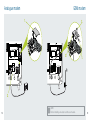
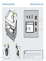
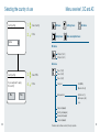
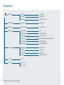
Image may differ 11 / 2013 Short Manual PIKO BA-Inverter with Energy Management EU Declaration of conformity The company KOSTAL Solar Electric GmbH Hanferstraße 6 79108 Freiburg i. Br. Germany hereby declares that the inverter PIKO BA to which this declaration refers, conforms to the following guidelines and standards. Directive 2004/108/EC Electromagnetic compatibility Directive 2006/95/EC Electrical Apparatus Low Voltage Directive Application of the CE marking in accordance with Appendix III, Section B:2013 KOSTAL Solar Electric GmbH – 2013-07-01 Werner Palm (Managing Director) Armin von Preetzmann (Development Manager) European Standards including relevant amendments EN 61000-3-2:2006 / A1:2009 / A2:2009 (Harmonic currents) EN 61000-3-3:2008 (Flicker) EN 61000-6-2:2005 / AC:2005 (Interference resistance for industrial environments) This declaration loses its validity if the device is modified or incorrectly connected. EN 61000-6-3:2007 / A1:2011 (Interference emission for domestic environments) This declaration certifies compliance with the mentioned regulations but does not ensure the properties. EN 62109-1: 2010 (safety of power converters Part 1) EN 62109-2: 2011 (safety of power converters Part 2) 2 This declaration applies to all identical copies of this product. The safety instructions in the product documentation provided must be observed! 3 Proper use The PIKO BA-Inverter converts DC current into AC current. Exclusion of liability The current can be used for the following: Any use that differs from or goes beyond the stated intended purpose is considered inappropriate. The manufacturer accepts no liability for any damage resulting from this. Modifications to the inverter are prohibited. The inverter may only be used if safe to operate and in technically perfect condition. Any instance of misuse will cause the termination of the warranty, guarantee and general liability of the manufacturer. nn for consumption nn to store the current in the battery of the system (PIKO BA-System) nn for feeds into the public mains grid The unit may only be used in grid-connected photovoltaic systems within the permissible power range and under the permissible environmental conditions. The device is not intended for mobile use. Inappropriate use can be hazardous and lead to injury or even death of the user or third parties. Material damage to the device and other equipment can also occur. The inverter may therefore only be used for its intended purpose. The PIKO BA-Inverter is equipped with an energy management system. This system controls based on technical and economic aspects of the use of electricity generated. 4 Only a qualified electrician may open the device. The inverter must be installed by an electrician who is responsible for observing the applicable standards and regulations. Work that could affect the electrical power system of the respective utility company at the site of the solar energy feed-in may only be carried out by qualified electricians expressly authorised (licensed) by the utility company. This includes changes to the factory preset parameters. The installer must always observe the regulations of the utility company. The utility company‘s specifications must always be observed when setting the parameters. 5 Type plate Scope of delivery Name and address of manufacturer Device type 3 Item number 4 MPP control range 5 Maximum input voltage DC 6 Maximum DC input current 7 Number of feed-in phases / Output voltage (nominal) 8 Maximum AC power 9 Maximum output current AC 10 Deviating output with country setting 11 Protective Class to IEC 62103 12 Protection type and ambient temperature range 13 Over voltage category 14 Requirements conforming to those of the built-in grid monitoring 15 Internal Item number 16 Serial number 17 Version of hardware 18 Version of parameter set 19 Version of firmware 20 Version of user interface 21 Date of the last update 22 Removable guarantee label 1 15 16 17 19 22 6 XXXXXABCXXXXX 18 20 21 ua 13 an 9 11 M VDE -AR-N 4105: 2011 -08 Art.-No.: NNNNNNNN Ser.-No.: XXXXXABCXXXXX HW: YYXXXX Par/ PIB: XX.XX FW: XX.XX UI: XX.XX Serviceupdate: XXXXXXXX 7 se r DIN V VDE V 0126 -1-1:A1:2012-02 6 U 14 5 te s 12 4 o 10 DCinput: UMPP = XXX...XXX V, UMAX = XXX V, IMAX = XXX A ACoutput: XXXXXXXXXX, XXXXX VA (cosΦ =1,adj.) max. XX.X A (XX:YYY YW (cosΦ =1)) Protective Class 1 IP 55, -20°C...60°C, OVC DC:II / AC:III N 8 XXXXXXXXXXXXX Art.-No.: XXXXXXXX ty 3 af e 2 Hanferstraße 6 – D-79108 Freiburg +49(0) 761-47744-100 www.kostal-solar-electric.com S 1 l 2 4x 1x L1 L2 L3 N PE 7 Selecting the installation side NOTE Observe the following instructions, or else warranty claims will be restricted. Protect from rain and water. Select stable installation location. No plasterboard or wooden walls. Protect from direct sunlight. Prevent access by children. 200 Select non-flammable installation location. Maintain safe distance from flammable materials or areas at risk of explosion. 100 NH3 Required cooling space is 200 mm vertical and 100 mm horizontal. Protect from dust, contamination and ammonia. Select vertical installation location. Ensure easy access and visible display. Ambient temperature must be between -20 °C and +60 °C. Air humidity must be between 4 % and 100 % (condensing). Ensure that people are not disturbed by operating noise. 90° °C/°F 8 % 9 To lift the inverter Installation Cooling space 100 1. 45 Lift here! max.10° Mounting spaces 200 20 45 100 Lift here! 74 2. 200 3. 10 PIKO BA-Inverter 11 Connecting AC and DC side LebensGEFAHR durch Stromschlag! Wechselrichter spannungsfrei schalten. Risk of death due to electrical shock! De-energise the inverter. Danger de mort par électrocution ! Mettre l’onduleur hors tension. ¡Peligro de muerte debido a electrocución! Desconectar el inversor de la tensión. Perigo de morte devido a choque elétrico! Desligar a tensão de corrente do inversor. Pericolo di morte per scossa elettrica! Eliminare la tensione dall‘inverter. Livsfare pga. elektrisk stød! Vekselstrømsomformeren skal kobles fra spændingen. Levensgevaar door elektrische schok! Schakel de omvormer spanningsvrij. Ohrožení života elektrickým proudem! Odpojte střídač od napětí. Pericol de electrocutare! Scoateţi ondulorul de sub tensiune. Smrtna nevarnost zaradi električnega udara! Razsmernik odklopite iz električne napetosti. Nebezpečenstvo ohrozenia života zásahom elektrického prúdu! Menič prepnite do beznapäťovej prevádzky. Elektrik çarpması nedeniyle hayati tehlike! İnvertörü gerilimsiz hale getirin. Κίνδυνος θανάτου από ηλεκτροπληξία! Αποσυνδέστε τον αντιστροφέα από το ρεύμα. 12 Опасност за живота поради токов удар. Изключвайте инвертора от напрежението. Livsfara på grund av elektrisk stöt! Koppla växelriktaren spänningsfri. Zagrożenie życia przez porażenie prądem! Odłączyć falownik od zasilania. Elektrilöögi oht! Lahutage vaheldi vooluvõrgust. Pavojus gyvybei dėl elektros srovės smūgio! Inverteriui nutraukite įtampos tiekimą. Elektriskās strāvas trieciena briesmas! Atslēgt invertoru no strāvas. Opasnost po život od strujnog udara! Isključiti izmjenjivač. Opasnost po život zbog strujnog udara! Isključiti izmjenjivač. Opasnost po život uslijed strujnog udara! Izmjenjivač isključite sa naponskog napajanja. Opasnost po život usled strujnog udara! Izmenjivač isključite sa naponskog napajanja. De-energising inverter: 1. OFF ON 2. 3. 4. Switch off DC side Switch off - AC side 1. At Inverter 2. At Batterysystem - S0/AL-out (when connected) - Battery (when connected) 5. 5 min OFF Safeguard Disconnect DC side Wait 5 minutes 13 Connecting AC, DC and battery side L1 L2 L3 N PE Country-specific installation L1.k Connecting battery - 1 + - L2.k L 2.l L3.k L3.l Connecting sensor Connecting AC Connecting main cable with sealing cap 2 + Sensor 14 L1.l Connecting DC side Battery DSL / CAN bus Backup Mode LAN Modem 3 Nm AC Second ground connection 15 Option: Connecting DC1 & DC2 in parallel DC1 DC2 Battery Data transfer Communicationboard II DSL or LAN and CAN bus DSL / LAN CAN bus Note 16 When using the parallel connection this feature must be acti vated under the menue Settings >> Hardware settings >> String connection >> Parallel connection. 17 Analogue modem GSM modem 1. 3. 2 oard B Kom 2 oard B Kom 2. 1. 2. Note 18 Before installing a modem, read the user manual. 19 Commissioning the inverter 1. Selecting the country of use 5 Nm Select Country setting Austria 2. 20 OFF ON 3. Enter ON Note Country setting „Germany VDE 0126“ may only be used with inverters installed in PV plants connected to the grid before 31.12.2011. (No displacement factor cosφ preset.) 21 Selecting the country of use Country setting Menu overview*, DC and AC 1. Select country DC menu Settings menu 2. H Enter Battery menu Own consumption menu AC menu Austria DC menu DC input 1 (U,I,P) DC input 2 (U,I,P) AC menu Country setting 3. Select YES Phase 1 (U,I,P) Phase 2 (U,I,P) Phase 3 (U,I,P) Do you really want to apply this country? 4. H Enter Total yield Yield (MWh) Operation time (h) Grid parameters Limitation on (%) Grid frequency (Hz) cos φ No Yes 22 Daily yield (diagram) Monthly yield (diagram) Annual yield (diagram) Total yield (diagram) Deviations due to software versions (UI level) is possible. * 23 Settings menu* 24 Basic settings Language Inverter name Date / time Select language Entering the name Set date / Set time of day Hardware settings String connection Paralell connection Battery settings Battery charge time Start time / End time Communication Network settings 1 Network settings 2 Router settings RS485 settings Portal configuration Event messages Auto IP IP address / Subnet mask External router / Router IP Bus termination / Bus bias voltage / RS485 address Portal code / Data export Immediately mailing On / Off Device information SW/HW version Serial number Country setting Certificate FW / HW / UI / PAR Serial number Country setting Certificate / Certificate index Function test Fan test Service menu Service code Factory settings Deviations due to software versions (UI level) is possible. * 25 Menu Battery* 26 Menu Consumption* Battery status 1 Charging status (%) Voltage (V) Charging (A) (Charge/Discharge) Battery status 2 Temperature (C°) Charge cycles Daily own consumption Own consumption (Wh) Own consumptions rate (%) Autonomy degree (%) Total own consumption Own consumption (Wh) Own consumptions rate (%) Autonomy degree (%) Current build. consump Battery (W) Solar generator (W) Grid (W) Phase-sel. Consumption Phase 1 (W) Phase 2 (W) Phase 3 (W) Deviations due to software versions (UI level) is possible. * 27 Technical data PIKO BA-Inverter PIKO BA-Inverter Unit Output side (AC) Input side (DC) Inverter type PIKO BA Max. PV power kWp 11 Recommended PV power kWp 4 - 11 MPP range with rated DC power V 440 - 850 Max. input voltage (Udcmax ) V 950 Rated output, cos j = 1 (Pac,r ) kW Max. output apparent power, cos φ, adj kVA 10 Rated output current A 14,5 Max. output current (Iacmax ) A 17,5 short circuit current (Peak / RMS) A 566 / 12,2 Min. input voltage (Udcmin ) V 180 Number of feed-in phases Rated input current A 11,5 Grid connection Max. input current (Idcmax ) A 12 Rated frequency (fr ) Max. input current with parallel connection A 24 Ext. current sensor Number of DC inputs 2 Number of independent MPP trackers 2 Battery input side (DC) 28 Unit 10 3 3/N/PE, AC, 400 V Hz 50 A 50 Dimensions (H x W x D) mm (inch) 90 x 105 x 54 (3.54 x 4.13 x 2.13) Max. cable diameter mm (inch) 13,5 (0.53) Rated current primary Precision method 1 Max. battery input voltage V 314 Min. battery input voltage V 211 Rated voltage battery input V 228 Max. charge current A 12 Efficiencies Max. discharge current A 12 Max. efficiency % 96,5 Max. European efficiency rate % 95,3 Mounting on top hat rail to DIN EN 60715 H 29 PIKO BA-Inverter Unit PIKO BA-Inverter System data System data Topology: without galvanic separation transformerless H Internal protection according to IEC 60529 IP 55 Electronic disconnection device integrated H Height mm (inch) 450 (17.72) Width mm (inch) 520 (20.47) Depth mm (inch) 230 (9.06) Weight kg (lb) 33 (72,75) Max. air throughput m³/h 188 Max. noise emission dBA 46 Ambient temperature °C (°F) -20...60 (-4...160) m above sea level 2000 % 4…100 Protection class according to IEC 62103 I Overvoltage category according to IEC 60664-1 Input side (PV-generator) II Overvoltage category according to IEC 60664-1 Output side (grid connection) III Degree of contamination 3 Enviromental category (outdoor installation) H Enviromental category (interior installation) H UV-resistance H Relative humidity (condensing) 2,5 Connection technology at input side – MC 4 H Connection technology at output side – spring-loaded terminal strip H Minimum cable cross-section of AC-connect-inline Minimum cable cross-section of DC-connect-inline mm² mm² Min. fusing on output side 4 B25, C25 Tightening torque of PE connection, outer Nm 3 Tightening torque of lid screws Nm 5 Operation protection 30 Unit RCCB Typ B nach EN62109-2 Max. installation altitude Various Warranty Years 5 Warranty extension optional Years 10 / 20 31 Service Hotline Germany and other countries 1 +49 761 47 74 42 22 France Belgium, Luxembourg +33 1 6138 4117 Greece +30 2310 477 555 Italy +39 011 97 82 420 Spain Portugal 2 +34 961 824 927 1 2 Language: German, English Language: Spanish, English 11 / 2013 edition, subject to technical changes and printing errors.