1
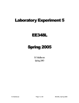
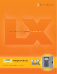
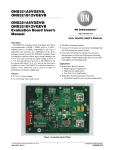
@ESPAN Alarm Technology ESPAN-01 Series Annunciator System Combination type User Manual (Rev. 1) ESP TECHNOLOGIES LIMITED www.esptechno.com @ESPAN Content Page Introduction 2 General Description 2 Overview - Annunciator System 3 Specifications 4 Master Alarming Module 6 Parameters Setting 7 Circuit Wiring Diagram 9 Power Supply Unit 10 Installation 11 Typical Wiring Diagram 14 Dimension 15 Procedure for factory repairing and returning 17 ESPAN01 Series – User Manual (Rev. 1) ‐ 1 ‐ www.esptechno.com @ESPAN Introduction The Annunciator system ESPAN-01 series incorporate the latest microprocessor technology to provide a versatile and flexible alarm system suitable for a wide range of applications. The basic system consists of a power supply unit, master alarm unit and window display units. The power supply unit is a universal AC or DC converter which can accept both AC and DC source with the wide range but the output shall be DC 24 V. The master alarm unit, normally have six ranges : 16 alarm point, 24 alarm point, 32 alarm point, 40 alarm point, 48 alarm point and 56 alarm module depended on demand selection. The layout of the window display module is flexible according to the requirement. The sizes of the window display units are as following: 30 x 30 and 30 x 60 mm. Lamp inside the window display unit can be LED or incandescent lamp upon request. The master alarm unit is a modern technology using microprocessor based and solid state designed. All setting parameters can be easily done via selector or dip-switch on the control card. General Description Optimizing an industrial installation requires automation of control and is usually accompanied by an alarm or supervisory system of certain parameters called “fault”. The aim is to attract the attention of the supervising personnel by an illuminated signal and alarm horn or buzzer, thus enabling proceeding to be taken. Rapid detection of any anomaly or excess of critical values will avoid unfortunate consequences, which could result from lack of interference. Alarm Sequence Fault Detector Item to be Horn/Buzzer Altered Definition of fault is expressed by the opening or closing of a contact. This information represents any modification of a physical or mechanical parameter converted into an electrical signal by the intermediary of a detector. ESPAN01 Series – User Manual (Rev. 1) ‐ 2 ‐ www.esptechno.com @ESPAN Overview - Annunciator System POWER SUPPLY MODULE ESPAN-01 COMBITYPE ESPAN ALARM TECHNOLOGY MASTER ALARM MODULE DISPLAYING MODULE LED LAMP OR INCANDESCENT ESPAN-02 SINGLE UNIT, LED TYPE (FLUSH MOUNT) ESPAN01 Series – User Manual (Rev. 1) ‐ 3 ‐ www.esptechno.com @ESPAN Specifications System Voltage Display Lamps : 24 Vdc + 10% Field contact voltage : (options) 24, 48, 110, 125 Vdc ± 10% Active alarm point : 16, 24, 32, 40, 48 & 56 (max) Temperature Range Storage : -10 to 70 °C Operating : -10 to 55 °C Humidity : up to 95% Power Source Input voltage : 110 - 350 Vdc or 90 - 250 Vac (50/60 Hz) Output voltage : 24 Vdc + 5% Output power : 30, 50, 75, 100, 150 & 300 Watt Output Lamp output : Flash light Audible alarm : Two channels output for audible alarm Repeat relay (option) : 24 Vdc Input coil, 1 output contact (rating: 10A 28 Vdc or 10A 120 Vac) Response time : 20 ms, nominal Display dimension Square window : 30 x 30 mm. (each - with one lamp supplied) Rectangular window : 30 x 60 mm. (each - with 2 lamps supplied) Power of display lamp : 2 watt/pc for incandescent lamp or 0.5 watt/pc for LED lamp ESPAN01 Series – User Manual (Rev. 1) ‐ 4 ‐ www.esptechno.com @ESPAN Sequence : Manual Reset Standard sequence : ANSI/ISA-S18.1-1981 (Annunciator sequences & specifications) STANDARD SIGNAL NORMAL ALERT RETURN TO NORMAL BEFORE ACKNOWLEDGEMENT ACK RESET RETURN TO NORMAL M-1-2-14 LAMP SOUND OFF SILENCE FLASH ALARM FLASH ALARM ON SILENCE OFF SILENCE OFF SILENCE Manual reset occurs after acknowledge when the process condition has turned to normal and the reset push button is pressed. Sequence : Automatic Reset Standard sequence : ANSI/ISA-S18.1-1981 (Annunciator sequences & specifications) STANDARD SIGNAL NORMAL ALERT RETURN TO NORMAL BEFORE ACKNOWLEDGEMENT ACKNOWLEDGEMENT BEFORE RETURN TO NORMAL RETURN TO NORMAL A-1-2-14 LAMP SOUND OFF SILENCE FLASH ALARM OFF SILENCE ON SILENCE OFF SILENCE Automatic reset occurs after acknowledge when the process condition has turned to normal. ESPAN01 Series – User Manual (Rev. 1) ‐ 5 ‐ www.esptechno.com @ESPAN Master Alarming Module Power consumption 1.8 Watt (at 24 Vdc) for 16 channel 2.0 Watt (at 24 Vdc) for 24 channel 2.2 Watt (at 24 Vdc) for 32 channel 2.4 Watt (at 24 Vdc) for 40 channel 2.6 Watt (at 24 Vdc) for 48 channel 2.8 Watt (at 24 Vdc) for 56 channel Alarming sequences Manual reset sequence (Lock-in type) In this mode, the momentary fault inputs will be latched until acknowledgement and reset to clear. Alarm device is silenced and stop flashing when acknowledged. Manual reset of acknowledge alarm can be done only after process conditions return to normal. Auto reset sequence (Non locking type) In this mode, the contacts return to normal on and acknowledge the alarm cause that alarm to reset. If alarm contact returns to normal before acknowledgement then the alarm will immediately reset on acknowledge. ESPAN01 Series – User Manual (Rev. 1) ‐ 6 ‐ www.esptechno.com @ESPAN Parameters Setting 1) Selecting Setup Menu 2) Flash Rate Setting 3) Operation Sequences Setting ESPAN01 Series – User Manual (Rev. 1) ‐ 7 ‐ www.esptechno.com @ESPAN 4) NO – NC Fault Contact Setting 5) Bell / Buzzer – Output Alarm Setting ESPAN01 Series – User Manual (Rev. 1) ‐ 8 ‐ www.esptechno.com @ESPAN 6) Circuit Wiring Diagram ESPAN01 Series – User Manual (Rev. 1) ‐ 9 ‐ www.esptechno.com @ESPAN Power Supply Unit This is an AC/DC converter regulated type, designed for surge protection and provides transient surge isolation between the station battery and the sensitive electronic components of the annunciator system. Fuse Protection is also protecting system from overload or short circuit on the output power supply. Model : PSU-30, 50, 75, 100, l50, 300 Output Power : 30, 50, 75, 100, 150 & 300 watt Efficiency : 85-95 % of full load Input Voltage (auto range) : 160 to 250 Vac : 110 to 350 Vdc Input Frequency : 47 to 440 Hz Temperature Range : 0 to 70 °C Output Voltage : 24 ± 5% Vdc Output Ripple Voltage : ± 150 mV p-p (max) at full load Hold up time : 10 ms (min) at 24 V Designed for World Wide Operation Reference EMI : Meets VDE B (VFG243B) CISPR22 Class B Safety requirements : IEC 950 / UL1950 Hardware Protection (on board) Primary safety current limit Output short circuit protection Thermal shutdown protects entire power supply ESPAN01 Series – User Manual (Rev. 1) ‐ 10 ‐ www.esptechno.com @ESPAN Installation Mounting Display Unit to panel Insert the unit from the front side. From the back, attach the mounting clamp (CA-1) ion. Hook to the square hole of the frame board and screw tightly. Place the mounting clamps evenly around the display unit. Fasten with the recommended torque 0.4 ~ 0.5 Nm. For wiring, secure the application terminal with a terminal screw in accordance with the polarity indication. Removing the window displaying unit The window displaying unit consists of a lens, legend plate, filter and lamp. To remove lens, insert the tip of a Philip screw driver into the side space of the case and gently rotate then the lens will come off. Use the fingers or tool to remove the lamp out. ESPAN01 Series – User Manual (Rev. 1) ‐ 11 ‐ www.esptechno.com @ESPAN When mounting Insert the nameplate, filters and front lens into the lens retains. To mount the window display, place the unit perpendicularly against the case with the two legs section in the left and right side and push in along the way. ESPAN01 Series – User Manual (Rev. 1) ‐ 12 ‐ www.esptechno.com @ESPAN How to connect system +24V / 0V PWR OPER RES / ACK / TEST / COM / 125COM24 BUZZER 1) +24V/ 0V BELL COM COM F01 ~ F16 ~ FX1~FX8 (MAX56) L01 ~ L16 ~ LX1 ~ LX8 (MAX56) : Input voltage must be DC 24 Vdc : Positive connects to +24 V and Negative connect to 0 V. 2) RES : must be connected to the reset push button switch (RES) which is N.O. contact and the opposite side of the push button switch must connect to COM. ACK : must be connected to the acknowledged (ACK) push button switch and do the same as RES, the purpose is to do horn stop. TEST : must be connected to the lamp test (LT) push button switch and do the same as RES. The purpose is for lamp checking. COM : must be connected to the push button switch RES, ACK and TEST. 3) 125 COM 24 (Notice) In case of Fault input signal is DC +125 V, -125 V must connect to 125 COM In case of Fault input signal is DC +24 V, -24 V must connect to COM 24 4) F01~F16~F32~F56 : must be connected to fault input signal or field contact. 5) BUZZER / BELL : can be selected and connected to Buzzer or Bell outside via primary power source. 6) COM / COM : must be connected to the DC 24 V (Negative pole) 7) L01~L16~L32~L56 : connect to the lamp of window display unit by point and the opposite side of these lamps are common and connect to the DC +24 V (Positive pole). ESPAN01 Series – User Manual (Rev. 1) ‐ 13 ‐ www.esptechno.com @ESPAN Typical Wiring Diagram ESPAN01 Series – User Manual (Rev. 1) ‐ 14 ‐ www.esptechno.com @ESPAN Dimension of Master Alarming Unit ESPAN01 Series – User Manual (Rev. 1) ‐ 15 ‐ www.esptechno.com @ESPAN Dimension of displaying unit 30 x 30 Dimension of displaying unit 30 x 60 ESPAN01 Series – User Manual (Rev. 1) ‐ 16 ‐ www.esptechno.com @ESPAN Procedure for factory repairing and returning A. Prepare a Return Material Authorization Form (available from ESPAN or its local representative) with the following information: Model and Serial Number of the equipment. Specify Failure Symptom Operating Environment (indoor, outdoor, temperature, vibration, etc.) Approximate date of installation or number of operating hours. Name and telephone number of contact person if questions arise. B. Enclose the information with the equipment and pack in a commercially accepted shipping container with sufficient packing material to ensure that no shipping damage will occur. Ship to the appropriate location as below Attention: Service Department ESP Technologies Ltd. 688/74, M.7, Laksi-square Building, Changwattana Road, Anusaowari-Bangkhen, Bangkhen, Bangkok 10220, Thailand Telephone: +66(0)25226245~7 Fax: +66(0)25226248 C. Your equipments will be tested, repaired and inspected at the factory and return within ten days (exclude shipping back period). D. In case of urgent service needs or repairing status enquiry, please contact the appropriate Service Department or your local ESPAN representative. WARRANTY: ESP Technologies Ltd. warrants equipment of its own manufacture to be free from defects in material and workmanship, under normal conditions of use and service. ESP Technologies Ltd. will replace any components found to be defective, upon its return, transportation charges prepaid, within one year of its original purchase. ESP Technologies Ltd. will extend the same warranty protection on accessories, which is extended or implied, beyond its obligation to replace any components involved. Such warranty is in lieu of all other warranties expressed or implied. ESPAN01 Series – User Manual (Rev. 1) ‐ 17 ‐ www.esptechno.com