1
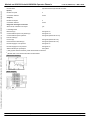
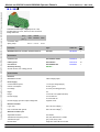
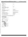
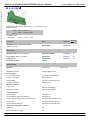
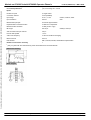
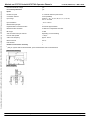
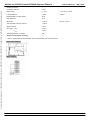
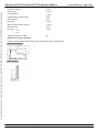
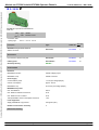
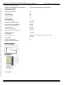
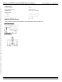
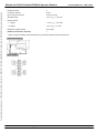
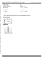
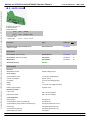
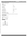
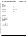
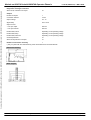
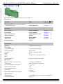
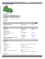
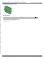
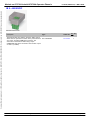
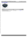
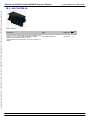
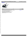
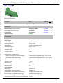
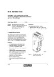
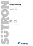
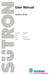
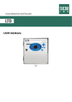
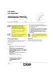
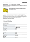
Module no:2836324 LabelId:2836324 Operator:Phoenix
13:51:19, Mittwoch, 1. März 2000
Courtesy of Steven Engineering, Inc. Ÿ 230 Ryan Way, South San Francisco, CA, 94080-6370 Ÿ Main Office: (650) 588-9200 Ÿ Outside Local Area: (800) 258-9200 Ÿ www.stevenengineering.com
IB IL INC Z
1 incremental encoder input, 4 digital inputs 24 V DC,
4 digital outputs 24 V DC, 500 mA, 3-wire connection
Design width 48.8
(IEC)
rigid
flexible
2
solid
stranded
AWG
0.2-1.5
0.2-1.5
24-16
[mm ]
Connection data
Spring clamp
Description
Type
Order No.
Pcs.
Pkt.
INTERBUS incremental encoder interface
terminal
IB IL INC
28 36 32 4
1
Connector set
IB IL SSI/INC-PLSET
27 32 47 3
1
Labeling field
IB IL FIELD 8
27 27 51 5
10
User manual
IB IL SSI/INC UM
27 32 56 7
1
Zack strip labeling,
several versions, see catalog part 3/4
ZBFM 6-...
each without connector set
Accessories
Technical data
Interfaces
INTERBUS local bus
Inline voltage jumper
Power supply
Communications power
7 V DC (via voltage jumper)
Current consumption
90 mA, typical
I/O voltage
24 V DC (via voltage jumper)
Ripple
5%
Range
19.2 to 30 V DC (ripple included)
Encoder supply
5 V DC/ 500 mA
24 V DC/ 500 mA
Encoder supply, input and output voltage from
segment circuit
Electrical isolation
Logic / I/Os
500 V AC test voltage )
I/Os / functional earth ground
500 V AC test voltage )
1
1
Incremental encoder input
Adjustable resolution
max 26 bits
Input frequencies
0 - 50 kHz (24V) or 0 - 500 kHz (5V)
Phoenix Contact Elektronischer Katalog
Page 1 / 2
Module no:2836324 LabelId:2836324 Operator:Phoenix
Courtesy of Steven Engineering, Inc. Ÿ 230 Ryan Way, South San Francisco, CA, 94080-6370 Ÿ Main Office: (650) 588-9200 Ÿ Outside Local Area: (800) 258-9200 Ÿ www.stevenengineering.com
Encoder data
13:51:19, Mittwoch, 1. März 2000
symmetrical and asymmetrical encoders
Inputs2)
Number of inputs
4
Connection method
3-wire
2
Outputs )
Number of outputs
4
Connection method
3-wire
Diagnostic messages via the bus
Short-circuit, overload of an output
yes
Local diagnostics
Bus active (D)
LED green on
Communications power not present (D)
LED green out
Communications power present/
bus not active (D)
LED green (flashes at 0.5 Hz)
I/O error (D)
LED green (flashes at 2 Hz)
Previous device defective (D)
LED green (flashes at 4 Hz)
Encoder supply 5 V DC present
LED green on
Encoder supply 24 V DC present
LED green on
Status indicator per input/output
LED yellow
1
) Only system with bus terminal, power terminal and I/O termnial
2
) Please refer to user manual for further technical data
Dimensional drawing
Block diagram
Phoenix Contact Elektronischer Katalog
Page 2 / 2
Module no:2836340 LabelId:2836340 Operator:Phoenix
13:51:30, Mittwoch, 1. März 2000
Courtesy of Steven Engineering, Inc. Ÿ 230 Ryan Way, South San Francisco, CA, 94080-6370 Ÿ Main Office: (650) 588-9200 Ÿ Outside Local Area: (800) 258-9200 Ÿ www.stevenengineering.com
IB IL SSI Z
1 absolute encoder input, 4 digital inputs 24 V DC,
4 digital outputs 24 V DC, 500 mA, 3-wire connection
Design width 48.8
(IEC)
rigid
flexible
2
solid
stranded
AWG
0.2-1.5
0.2-1.5
24-16
[mm ]
Connection data
Spring clamp
Description
Type
Order No.
Pcs.
Pkt.
INTERBUS absolute encoder interface terminal
IB IL SSI
28 36 34 0
1
Connector set
IB IL SSI/INC-PLSET
27 32 47 3
1
Labeling field
IB IL FIELD 8
27 27 51 5
10
User manual
IB IL SSI/INC UM
27 32 56 7
1
Zack strip labeling,
several versions, see catalog part 3/4
ZBFM 6-...
Accessories
Technical data
Interfaces
INTERBUS local bus
Inline voltage jumper
Power supply
Communications power
7 V DC (via voltage jumper)
Current consumption
40 mA, typical
I/O voltage
24 V DC (via voltage jumper)
Ripple
5%
Range
19.2 to 30 V DC (ripple included)
Encoder supply
5 V DC/ 500 mA
24 V DC/ 500 mA
Encoder supply, input and output voltage from
segment circuit
Electrical isolation
Logic / I/Os
500 V AC test voltage )
I/Os / functional earth ground
500 V AC test voltage )
1
1
Absolute encoder input
Adjustable resolution
max 26 bits
Transmission frequency (clock)
200, 400, 800 kHz and 1.5 Mhz
Transmission type
gray code, binary code
Encoder data
single-turn and multi-turn encoder
Phoenix Contact Elektronischer Katalog
Page 1 / 2
Module no:2836340 LabelId:2836340 Operator:Phoenix
Encoder data
13:51:30, Mittwoch, 1. März 2000
single-turn and multi-turn encoder
Courtesy of Steven Engineering, Inc. Ÿ 230 Ryan Way, South San Francisco, CA, 94080-6370 Ÿ Main Office: (650) 588-9200 Ÿ Outside Local Area: (800) 258-9200 Ÿ www.stevenengineering.com
Inputs2)
Number of inputs
4
Connection method
3-wire
2
Outputs )
Number of outputs
4
Connection method
3-wire
Diagnostic messages via the bus
Short-circuit, overload of an output
yes
Local diagnostics
Bus active (D)
LED green on
Communications power not present (D)
LED green out
Communications power present/
bus not active (D)
LED green (flashes at 0.5 Hz)
I/O error (D)
LED green (flashes at 2 Hz)
Previous device defective (D)
LED green (flashes at 4 Hz)
Encoder supply 5 V DC present
LED green on
Encoder supply 24 V DC present
LED green on
Status indicator per input/output
LED yellow
1
) Only in system with bus terminal, power terminal and I/O terminal
2
) Please refer to the user manual or further technical data
Dimensional drawing
Block diagram
Phoenix Contact Elektronischer Katalog
Page 2 / 2
Module no:2726285 LabelId:2726285 Operator:Phoenix
12:42:14, Mittwoch, 1. März 2000
Courtesy of Steven Engineering, Inc. Ÿ 230 Ryan Way, South San Francisco, CA, 94080-6370 Ÿ Main Office: (650) 588-9200 Ÿ Outside Local Area: (800) 258-9200 Ÿ www.stevenengineering.com
IB IL AI 2/SF Z
2 inputs, 0-20 mA, 4-20 mA, 20 mA, 0-10 V, 10 V, 2-wire connection
Design width 12.2
(IEC)
rigid
solid
2
[mm ]
flexible
stranded AWG
Connection data
- Spring cage
0.2-1.5
0.2-1.5
24-16
Pcs. Pkt.
Description
Type
Order No.
INTERBUS analog input terminal block
without connector
IB IL AI 2/SF
27 26 28 5
1
Shield connector, without color print
IB IL SCN-6 SHIELD
27 26 35 3
10
I/O connector, without color printt
IB IL SCN-8
27 26 33 7
10
Labeling field
IB IL FIELD 2
27 27 50 1
10
Zack strip labeling
ZBFM 6-...
Accessories
Technical data
current intput
Interfaces
voltage input
INTERBUS local bus
INLINE voltage jumper
Power supply
Communication power
7 V DC (via voltage jumper)
Current consumption
approx. 45 mA
Analog voltage
24 V DC (via voltage jumper)
Current consumption
approx. 12 mA
Electrical isolation
Logic UL/I/O
500 V AC test voltage )
I/O/functional earth
500 V AC test voltage )
1
1
Local diagnostics
Bus active (D)
LED green on
Communication power not present (D)
LED green off
Communication power present/ bus inactive (D)
LED green (flashes with 0.5 Hz)
I/O error (D)
LED green (flashes with 2 Hz)
Previous device faulty (D)
LED green (flashes with 4 Hz)
Diagnostics messages via the bus
Overrange
yes
Error of internal I/O voltage
yes
Phoenix Contact Elektronischer Katalog
Page 1 / 2
Module no:2726285 LabelId:2726285 Operator:Phoenix
g
Courtesy of Steven Engineering, Inc. Ÿ 230 Ryan Way, South San Francisco, CA, 94080-6370 Ÿ Main Office: (650) 588-9200 Ÿ Outside Local Area: (800) 258-9200 Ÿ www.stevenengineering.com
Line interrupt detection
12:42:14, Mittwoch, 1. März 2000
y
yes, for the range of 4 - 20 mA
Inputs
Number of inputs
2, single ended
Connection method
2-wire (shielded)
Input range
0- 10 V, ± 10 V
0-20mA, 4-20mA, 20mA
Input resistance
220 k Ω
50Ω
Measurement principle
successive approximation
Representation of measured value
16 bits two’s complement
Measured value resolution
16 bits (15 bits + sign)
Bit weight
333.33 µV
A/D conversion time per channel
100 µs
Process data update
< 2 ms
3 dB cut-off frequency
15 Hz/ 40 Hz without averaging
Basic error limit
0.015 %
Data formats
IBS IL, IBS ST, IBS RT, standardized representation
Number of connectors necessary
1
0.666µA, 0.533µA
1
) Only in system with bus terminal block, power terminal block and I/O terminal block
Dimensional drawing
Block diagram
Phoenix Contact Elektronischer Katalog
Page 2 / 2
Module no:2726308 LabelId:2726308 Operator:Phoenix
12:42:25, Mittwoch, 1. März 2000
Courtesy of Steven Engineering, Inc. Ÿ 230 Ryan Way, South San Francisco, CA, 94080-6370 Ÿ Main Office: (650) 588-9200 Ÿ Outside Local Area: (800) 258-9200 Ÿ www.stevenengineering.com
IB IL TEMP 2 RTD Z
2 inputs, RTD (resistance temperature detector),
2, 3, 4-wire connection
Design width 12.2
(IEC)
rigid
solid
2
[mm ]
flexible
stranded AWG
Connection data
- Spring cage
0.2-1.5
0.2-1.5
24-16
Pcs. Pkt.
Description
Type
Order No.
INTERBUS analog input terminal block
without connector
IB IL TEMP 2 RTD
27 26 30 8
1
Shield connector, without color print
IB IL SCN-6 SHIELD
27 26 35 3
10
I/O connector, without color printt
IB IL SCN-8
27 26 33 7
10
Labeling field
IB IL FIELD 2
27 27 50 1
10
Zack strip labeling
ZBFM 6-...
Accessories
Technical data
Interfaces
INTERBUS local bus
INLINE voltage jumper
Power supply
Communication power
7 V DC (via voltage jumper)
Current consumption
approx. 45 mA
Analog voltage
24 V DC (via voltage jumper)
Current consumption
approx. 12 mA
Electrical isolation
Logic UL/I/O
500 V AC test voltage )
I/O/functional earth
500 V AC test voltage )
1
1
Local diagnostics
Bus active (D)
LED green off
Communication power not present (D)
LED green (flashes with 0.5 Hz)
Communication power present/ bus inactive (D)
LED green (flashes with 2 Hz)
I/O error (D)
LED green (flashes with 4 Hz)
Previous device faulty (D)
LED green on
Status display per input
LED yellow
Diagnostics messages via the bus
Overrange
Phoenix Contact Elektronischer Katalog
yes
Page 1 / 2
Courtesy of Steven Engineering, Inc. Ÿ 230 Ryan Way, South San Francisco, CA, 94080-6370 Ÿ Main Office: (650) 588-9200 Ÿ Outside Local Area: (800) 258-9200 Ÿ www.stevenengineering.com
Module no:2726308 LabelId:2726308 Operator:Phoenix
Overrange
yes
Error of internal I/O voltage
yes
Line interrupt detection
yes
12:42:25, Mittwoch, 1. März 2000
Inputs
Number of inputs
2
Connection method
2, 3, 4-wire (shielded)
Input range
PT, NI 10-2000 (DIN/SAMA), Cu 10/50/53 KTY 81,
KTY 84
Input resistance
–
Measurement principle
0…4000 Ω
Representation of measured value
successive approximation
Measured value resolution
16 bits two’s complement and other
Bit weight
16 bits
A/D conversion time per channel
depending on sensor/setting
Process data update
< 100 µs
3 dB cut-off frequency
approx. 20 ms
Basic error limit
0.01 %
Data formats
400 µA
Number of connectors necessary
1
1
) Only on system with bus terminal block, power terminal block and I/O terminal block
Dimensional drawing
Block diagram
Phoenix Contact Elektronischer Katalog
Page 2 / 2
Module no:2727763 LabelId:2727763 Operator:Phoenix
12:43:26, Mittwoch, 1. März 2000
Courtesy of Steven Engineering, Inc. Ÿ 230 Ryan Way, South San Francisco, CA, 94080-6370 Ÿ Main Office: (650) 588-9200 Ÿ Outside Local Area: (800) 258-9200 Ÿ www.stevenengineering.com
IB IL TEMP 2 UTH Z
2 inputs, TC (thermocouple),2-wire connection
Design width 12.2
(IEC)
rigid
solid
2
[mm ]
flexible
stranded AWG
Connection data
- Spring cage
0.2-1.5
0.2-1.5
24-16
Pcs. Pkt.
Description
Type
Order No.
INTERBUS analog input terminal block
without connector
IB IL TEMP 2 UTH
27 27 76 3
1
Shield connector, without color print
IB IL SCN-6 SHIELD
27 26 35 3
10
I/O connector, without color printt
IB IL SCN-8
27 26 33 7
10
Labeling field
IB IL FIELD 2
27 27 50 1
10
Zack strip labeling
ZBFM 6-...
Accessories
Technical data
Interfaces
INTERBUS local bus
INLINE voltage jumper
Power supply
Communication power
7 V DC (via voltage jumper)
Current consumption
approx. 45 mA
Analog voltage
24 V DC (via voltage jumper)
Current consumption
approx. 12 mA
Electrical isolation
Logic UL/I/O
500 V AC test voltage )
I/O/functional earth
500 V AC test voltage )
1
1
Local diagnostics
Bus active (D)
LED green on
Communication power not present (D)
LED green off
Communication power present/ bus inactive (D)
LED green (flashes with 0.5 Hz)
I/O error (D)
LED green (flashes with 2 Hz)
Previous device faulty (D)
LED green (flashes with 4 Hz)
Status display per input
LED yellow
Diagnostics messages via the bus
yes
Overrange
E
fi t
l I/O
lt
Phoenix Contact Elektronischer Katalog
Page 1 / 2
Courtesy of Steven Engineering, Inc. Ÿ 230 Ryan Way, South San Francisco, CA, 94080-6370 Ÿ Main Office: (650) 588-9200 Ÿ Outside Local Area: (800) 258-9200 Ÿ www.stevenengineering.com
Module no:2727763 LabelId:2727763 Operator:Phoenix
Error of internal I/O voltage
yes
Line interrupt detection
yes
12:43:26, Mittwoch, 1. März 2000
Inputs
Number of inputs
2 + external reference point sensor
Connection method
2-wire (shielded)
Input range
sensors: J, K, L, U, B, E, N, R, S, T, C, W, HK;
ext. CJ: PT 1000
Input resistance
- 15 to + 85 mV
Measurement principle
–
Representation of measured value
successive approximation
Measured value resolution
16 bits two’s complement and other
Bit weight
16 bits
A/D conversion time per channel
depending on sensor/setting
Process data update
< 100 µs
3 dB cut-off frequency
approx. 20 ms
Basic error limit
0.01 %
Data formats
–
Number of connectors necessary
1
1
) Only on system with bus terminal block, power terminal block and I/O terminal block
Dimensional drawing
Block diagram
Phoenix Contact Elektronischer Katalog
Page 2 / 2
Module no:2726298 LabelId:2726298 Operator:Phoenix
12:42:19, Mittwoch, 1. März 2000
Courtesy of Steven Engineering, Inc. Ÿ 230 Ryan Way, South San Francisco, CA, 94080-6370 Ÿ Main Office: (650) 588-9200 Ÿ Outside Local Area: (800) 258-9200 Ÿ www.stevenengineering.com
IB IL AO 1/SF Z
1 output, 0-20 mA, 4-20 mA, 0-10 V
2-wire connection
Design width 24.4
(IEC)
rigid
solid
2
[mm ]
flexible
stranded AWG
Connection data
- Spring cage
0.2-1.5
0.2-1.5
24-16
Pcs. Pkt.
Description
Type
Order No.
INTERBUS analog output terminal block,
without connector
IB IL AO 1/SF
27 26 29 8
1
Shield connector, without color print
IB IL SCN-6 SHIELD
27 26 35 3
10
I/O connector, without color printt
IB IL SCN-8
27 26 33 7
10
Labeling field
IB IL FIELD 2
27 27 50 1
10
Zack strip labeling
ZBFM 6-...
Accessories
Technical data
current input
Interfaces
voltage input
INTERBUS local bus
INLINE voltage jumper
Power supply
Communication power
7 V DC (via voltage jumper)
Current consumption
approx. 30 mA
Analog voltage
24 V DC (via voltage jumper)
Current consumption
approx. 50 mA
Electrical isolation
Logic UL/I/O
500 V AC test voltage )
I/O/functional earth
500 V AC test voltage )
1
1
Local diagnostics
Bus active (D)
LED green on
Communication power not present (D)
LED green off
Communication power present/bus inactive (D)
LED green (flashes with 0.5 Hz)
I/O error (D)
LED green (flashes with 2 Hz)
Previous device faulty (D)
LED green (flashes with 4 Hz)
15 V I/O voltage present (UB)
LED green on
Outputs
Phoenix Contact Elektronischer Katalog
Page 1 / 2
Courtesy of Steven Engineering, Inc. Ÿ 230 Ryan Way, South San Francisco, CA, 94080-6370 Ÿ Main Office: (650) 588-9200 Ÿ Outside Local Area: (800) 258-9200 Ÿ www.stevenengineering.com
Module no:2726298 LabelId:2726298 Operator:Phoenix
12:42:19, Mittwoch, 1. März 2000
Number of outputs
1
Connection method
2-wire
Output range
0…10 V
4…20 mA, 0…20 mA
Load impedance
> 5 kΩ
< 500 Ω
Representation of output values
16 bit
DAC resolution
16 bit
Bit weight
0.15 mV
A/D conversion time per channel
< 100 µs
Basic error limit
0.05 %
Error type
U OUT
± 0.5 %
IOUT
± 0.8 %
Transient protection of outputs
yes
Number of connectors necessary
1
0.24 µA, 0.31 µA
1
) Only on system with bus terminal block, power terminal block and I/O terminal block
Dimensional drawing
Block diagram
Phoenix Contact Elektronischer Katalog
Page 2 / 2
Module no:2727776 LabelId:2727776 Operator:Phoenix
12:43:34, Mittwoch, 1. März 2000
Courtesy of Steven Engineering, Inc. Ÿ 230 Ryan Way, South San Francisco, CA, 94080-6370 Ÿ Main Office: (650) 588-9200 Ÿ Outside Local Area: (800) 258-9200 Ÿ www.stevenengineering.com
IB IL AO 1/U/SF Z
1 output, 0-10 V
2-wire connection
Design width 12.2
(IEC)
rigid
solid
2
[mm ]
flexible
stranded AWG
Connection data
- Spring cage
0.2-1.5
0.2-1.5
24-16
Pcs. Pkt.
Description
Type
Order No.
INTERBUS analog output terminal block
without connector
IB IL AO 1/U/SF
27 27 77 6
1
Shield connector, without color print
IB IL SCN-6 SHIELD
27 26 35 3
10
I/O connector, without color printt
IB IL SCN-8
27 26 33 7
10
Labeling field
IB IL FIELD 2
27 27 50 1
10
Zack strip labeling
ZBFM 6-...
Accessories
Technical data
Interfaces
INTERBUS local bus
INLINE voltage jumper
Power supply
Communication power
7 V DC (via voltage jumper)
Current consumption
approx. 30 mA
Analog voltage
24 V DC (via voltage jumper)
Current consumption
approx. 15 mA
Electrical isolation
Logic UL/I/O
500 V AC test voltage )
I/O/functional earth
500 V AC test voltage )
1
1
Local diagnostics
Bus active (D)
LED green on
Communication power not present (D)
LED green off
Communication power present/bus inactive (D)
LED green (flashes with 0.5 Hz)
I/O error (D)
LED green (flashes with 2 Hz)
Previous device faulty (D)
LED green (flashes with 4 Hz)
15 V I/O voltage present (UB)
–
Outputs
Number of outputs
Phoenix Contact Elektronischer Katalog
1
Page 1 / 2
Module no:2727776 LabelId:2727776 Operator:Phoenix
Courtesy of Steven Engineering, Inc. Ÿ 230 Ryan Way, South San Francisco, CA, 94080-6370 Ÿ Main Office: (650) 588-9200 Ÿ Outside Local Area: (800) 258-9200 Ÿ www.stevenengineering.com
p
Connection method
2-wire
Output range
0…10 V
Load impedance
> 5 kΩ
Representation of output values
16 bit
DAC resolution
16 bit
Bit weight
0.15 mV
A/D conversion time per channel
< 100 µs
Basic error limit
0.05 %
Error type
U OUT
± 0.5 %
IOUT
–
Transient protection of outputs
yes
Number of connectors necessary
1
12:43:34, Mittwoch, 1. März 2000
1
) Only on system with bus terminal block, power terminal block and I/O terminal block
Dimensional drawing
Block diagram
Phoenix Contact Elektronischer Katalog
Page 2 / 2
Module no:2727886 LabelId:2727886 Operator:Phoenix
12:43:39, Mittwoch, 1. März 2000
Courtesy of Steven Engineering, Inc. Ÿ 230 Ryan Way, South San Francisco, CA, 94080-6370 Ÿ Main Office: (650) 588-9200 Ÿ Outside Local Area: (800) 258-9200 Ÿ www.stevenengineering.com
IB IL 24 SL Z
INTERBUS-Loop branch terminal blocks
width 24,4
(IEC)
rigid
solid
2
[mm ]
flexible
stranded AWG
Connection data
- Spring cage
0.2-1.5 0.2-1.5
24-16
Pcs. Pkt.
Description
Type
Order No.
INTERBUS Loop branch terminal,
without connector
IB IL 24 SL
27 27 88 6
1
I/O connector, without color print
IB IL SCN-8
27 26 33 7
10
Labeling field
IB IL FIELD 2
27 27 50 1
10
Zack strip labeling
ZBFM 6-...
Accessories
Technical data
Interfaces
INTERBUS local bus
INLINE voltage jumper
INTERBUS-Loop
INLINE connector
Power supply
Communication power
7 V DC (via voltage jumper)
Current consumption
approx. 50 mA
INTERBUS Loop
28.5 V DC (via voltage jumper)
INTERBUS Loop data
max. total distance
200 m
max. distance between two devices
20 m
max. distance from 1st device
20 m
Total permissible current consumption of devices
1.8 A
Local diagnostics
Supply INTERBUS Loop present
LED green (USL)
Number of connectors necessary
2
Dimensional drawing
Phoenix Contact Elektronischer Katalog
Page 1 / 2
Courtesy of Steven Engineering, Inc. Ÿ 230 Ryan Way, South San Francisco, CA, 94080-6370 Ÿ Main Office: (650) 588-9200 Ÿ Outside Local Area: (800) 258-9200 Ÿ www.stevenengineering.com
Module no:2727886 LabelId:2727886 Operator:Phoenix
Phoenix Contact Elektronischer Katalog
12:43:39, Mittwoch, 1. März 2000
Block diagram
Page 2 / 2
Module no:2726188 LabelId:2726188 Operator:Phoenix
12:41:30, Mittwoch, 1. März 2000
Courtesy of Steven Engineering, Inc. Ÿ 230 Ryan Way, South San Francisco, CA, 94080-6370 Ÿ Main Office: (650) 588-9200 Ÿ Outside Local Area: (800) 258-9200 Ÿ www.stevenengineering.com
IBS IL 24 BK-T Z
INTERBUS bus terminal module, 24 V DC
Width 48.8
(IEC)
2
[mm ]
rigid
solid
flexible
stranded AWG
Connection data
- Spring cage
0.2-1.5
0.2-1.5
24-16
Pcs. Pkt.
Description
Type
Order No.
INTERBUS bus terminal module,
without connector
IBS IL 24 BK-T
27 26 18 8
1
Connector set
IB IL BK-PLSET
27 27 79 2
1
Labeling field
IB IL FIELD 8
27 27 51 5
10
End clamp
CLIPFIX 35
30 22 21 8
1
Zack strip labeling
ZBFM 6-...
Accessories
Technical data
Interfaces
INTERBUS remote bus (incoming/outgoing)
2 x 6-pos INLINE shield connector
Supply voltage
8-pos. INLINE input connector
INTERBUS local bus
INLINE voltage jumper
Power supply
Supply voltage
– Nominal value
24 V DC
– Ripple
5%
– Range
19 to 30 V DC (including ripple)
Current consumption
without connected IB IL-I/O terminals
approx. 90 mA
Max. total perm. curr. consumption of all I/O
terminals
Communication power (7 V)
≤2A
Analog supply (24 V)
≤ 0.5 A
Electrical isolation
Incoming remote bus/outgoing remote bus/local bus
500 V AC test voltage
INTERBUS data
max. distance from next remote bus station
Phoenix Contact Elektronischer Katalog
400 m
Page 1 / 2
Courtesy of Steven Engineering, Inc. Ÿ 230 Ryan Way, South San Francisco, CA, 94080-6370 Ÿ Main Office: (650) 588-9200 Ÿ Outside Local Area: (800) 258-9200 Ÿ www.stevenengineering.com
Module no:2726188 LabelId:2726188 Operator:Phoenix
12:41:30, Mittwoch, 1. März 2000
Number of connectable modules
63
Number of connectable INLINE terminals (without
additional power terminal)
20 (observe total permissible current consumption)
Programmable functions
Local bus branch disabled
yes
Local bus reset
yes
Local bus disabled
yes
Remote bus disabled
yes
Remote bus reset
yes
Local diagnostics
Remote bus active (BA)
LED green
Remote bus connection OK (RC)
LED green
Outgoing remote bus disabled (RD)
LED red
Local bus branch disabled (LD)
LED red
Local bus error (E)
LED red
Communication power (UL)
LED green
Supply voltage segment circuit (SG)
LED green
Operating voltage (US)
LED green
Local functions
Reconfiguration input
a pushbutton can be connected via an 8-pos. INLINE
connector
General data
Polarity reversal protection
yes
Connector set for bus terminal
1
Dimensional drawing
Block diagram
Phoenix Contact Elektronischer Katalog
Page 2 / 2
Module no:2729800 LabelId:2729800 Operator:Phoenix
12:44:09, Mittwoch, 1. März 2000
Courtesy of Steven Engineering, Inc. Ÿ 230 Ryan Way, South San Francisco, CA, 94080-6370 Ÿ Main Office: (650) 588-9200 Ÿ Outside Local Area: (800) 258-9200 Ÿ www.stevenengineering.com
ILC 200 IB Z
Inline Remote Field Controller
Design width 960
IBS c
AC
Description
Type
Order No.
Pcs.
Pkt.
Inline Controller, with electrical isolation
Remote Field Controller for INTERBUS Inline
ILC 200 IB
27 29 80 0
1
27 29 71 6
1
27 29 72 9
1
User manual,
for the Inline Controller
Automation software IBS PC WORX
German ILC 200 IB UM
English ILC 200 IB UM E
IBS PC WORX .. (see info)
Accessories
Connector set
ILC IB-PLSET
27 29 62 2
1
Connection cable, to connect Remote Field
Controllers to a PC (RS-232) for PC WORX,
3 m in length
ILC PRG CAB
27 29 63 5
1
27 54 28 6
1
27 54 80 4
1
27 53 82 1
1
27 51 00 1
1
Additional documentation,
Installation Manual: Structure
and installation of the INTERBUS system
German IBS SYS INST UM
I/O Systems Manual: Collection
of data sheets relating to INTERBUS
components
German IBS SYS PRO UM
English IBS SYS INST UM E
English IBS SYS PRO UM E
Technical data
Mechanical design
Format
960 x 129 x 70.5 mm
Interfaces
Higher-level INTERBUS remote bus (slave)
2 x 6-pos. Inline shield connector
Supply voltage
8-pos. Inline connector
INTERBUS local bus (master)
Inline voltage jumper
Parameterization/operation/diagnostics
RS 232C, 6-pos. MINI-DIN connector (PS/2)
Integrated inputs /outputs
2 Inline double signal connector
IEC 61131 runtime system
Processing speed
0.8 ms for 1K word or 1.6 ms for 1K bit instruction
Program memory
384 Kbyte
Number of control tasks
3
Phoenix Contact Elektronischer Katalog
Page 1 / 2
Courtesy of Steven Engineering, Inc. Ÿ 230 Ryan Way, South San Francisco, CA, 94080-6370 Ÿ Main Office: (650) 588-9200 Ÿ Outside Local Area: (800) 258-9200 Ÿ www.stevenengineering.com
Module no:2729800 LabelId:2729800 Operator:Phoenix
Number of control tasks
3
Remanent data memory
8 Kbyte NVRAM
12:44:09, Mittwoch, 1. März 2000
Power supply
Nominal value
24 V DC
Ripple
5%
Range
19.2 to 30 V
Current consumption
(without connected I/O terminals)
approx. 100 mA
Max. total permissible current consumption of all I/O
terminals
Communications power (7 V DC)
≤ 1.5 A
Analog supply (24 V DC)
0.5 A
INTERBUS
Number of process data words (slave)
0..10 words (configurable)
Number of PCP words (slave)
0, 1, 2 or words PCP (configurable)
Electrical isolation incoming/outgoing remote bus (slave)
500 V AC test voltage
Max. number of Inline terminals that can be connected
63 (observe current consumption)
Local diagnostics
INTERBUS
LED: BA, RC, RD, LD
Power supply
LED: UL, UM, US
IEC 61131 runtime system
LED: FCRUN, SYSFAIL, RDY/RUN, BSA, FAIL, PF
Dimensional drawing
Phoenix Contact Elektronischer Katalog
Page 2 / 2
Module no:2836337 LabelId:2836337 Operator:Phoenix
13:51:25, Mittwoch, 1. März 2000
Courtesy of Steven Engineering, Inc. Ÿ 230 Ryan Way, South San Francisco, CA, 94080-6370 Ÿ Main Office: (650) 588-9200 Ÿ Outside Local Area: (800) 258-9200 Ÿ www.stevenengineering.com
IB IL CNT Z
1 counter input, 1 control input, 1 output, 24 V DC, 500 mA,
3-wire connection
Design width 24.4
(IEC)
rigid
flexible
2
solid
stranded
AWG
0.2-1.5
0.2-1.5
24-16
[mm ]
Connection data
Spring clamp
Description
Type
Order No.
Pcs.
Pkt.
INTERBUS counter terminal,
without connector set
IB IL CNT
28 36 33 7
1
Connector set
IB IL AO/CNT-PLSET
27 32 66 4
1
Labeling field
IB IL FIELD 2
27 27 50 1
10
Zack strip labeling,
several versions, see catalog part 3/4
ZBFM 6-...
08 03 57 9
Accessories
Technical Data
Interfaces
INTERBUS local bus
Inline voltage jumper
Power supply
Communications power
7 V DC (via voltage jumper)
Current consumption
45 mA, typical
I/O voltage
24 V DC (via voltage jumper)
Ripple
5%
Range
19.2 to 30 V DC (ripple included)
Initiator power supply
main circuit
Switching output
segment circuit
Electrical isolation
Logic / serial interface
500 V AC test voltage )
I/O / functional earth
500 V AC test voltage )
1
1
Counter input
Operating modes
event counting, frequency/time measuring, pulse
generation
Input frequency
50 kHz
Input voltage
24 V DC/ 5 V DC
Input current
5 mA, typical
Control input
Phoenix Contact Elektronischer Katalog
Page 1 / 2
Module no:2836337 LabelId:2836337 Operator:Phoenix
13:51:25, Mittwoch, 1. März 2000
Courtesy of Steven Engineering, Inc. Ÿ 230 Ryan Way, South San Francisco, CA, 94080-6370 Ÿ Main Office: (650) 588-9200 Ÿ Outside Local Area: (800) 258-9200 Ÿ www.stevenengineering.com
Control input
Connection method
3-wire
Input voltage
24 V DC/ 5 V DC
Input current
5 mA, typical
Outputs
Number of outputs
1
Connection method
3-wire
Output voltage
24 V DC
Output current
500 mA
Diagnostic messages via the bus
Short-circuit of the initiator supply
yes
Local diagnostics
Bus active (D)
LED green on
Communications power not present (D)
LED green out
Communications power present /
bus not active (D)
LED green (flashes at 0.5 Hz)
I/O error (D)
LED green (flashes at 2 Hz)
Previous device defective (D)
LED green (flashes at 4 Hz)
Counter input source active (S)
LED yellow on
Control input gate active (G)
LED yellow on
Short circuit of the initiator supply (E)
LED red on
Output active
LED yellow on
1
) Only in system with bus terminal, power terminal and I/O terminal
Dimensional drawing
Block diagram
Phoenix Contact Elektronischer Katalog
Page 2 / 2
Module no:2836706 LabelId:2836706 Operator:Phoenix
13:51:50, Mittwoch, 1. März 2000
Courtesy of Steven Engineering, Inc. Ÿ 230 Ryan Way, South San Francisco, CA, 94080-6370 Ÿ Main Office: (650) 588-9200 Ÿ Outside Local Area: (800) 258-9200 Ÿ www.stevenengineering.com
IB IL 120 DI 1
1 input, 120 V AC
4-wire connection
Design width 12.2
(IEC)
rigid
solid
2
[mm ]
flexible
stranded AWG
Connection data
- Spring cage
0.2-1.5
0.2-1.5
24-16
Pcs. Pkt.
Description
Type
Order No.
INTERBUS digital input terminal block
without connector
IB IL 120 DI 1
28 36 70 6
1
I/O connector, with color print
IB IL SCN-8-CP
27 27 60 8
10
I/O connector, without color printt
IB IL SCN-8
27 26 33 7
10
Marker label
IB IL FIELD 8
27 27 51 5
10
Zack strip labeling
ZBFM 6-...
Accessories
Technical data
Interfaces
INTERBUS local bus
INLINE voltage jumper
Power supply
Communication power
7 V DC (via voltage jumper)
Current consumption
approx. 30 mA
I/O voltage
120 V AC (via voltage jumper)
Ripple
10 %
Range
108 to 132 V AC (ripple included)
Drawing initiator supply
segment circuit
Electrical isolation
Logic UL/I/O
1500 V AC test voltage )
I/O/functional earth
1500 V AC test voltage )
1
1
Local diagnostics
Bus active (D)
LED green on
Communication power not present (D)
LED green off
Communication power present/ bus inactive (D)
LED green (flashes at 0.5 Hz)
Previous/ next device faulty (D)
LED green (flashes at 4 Hz)
Status display per input
LED yellow
Inputs
Phoenix Contact Elektronischer Katalog
Page 1 / 2
Module no:2836706 LabelId:2836706 Operator:Phoenix
13:51:50, Mittwoch, 1. März 2000
Courtesy of Steven Engineering, Inc. Ÿ 230 Ryan Way, South San Francisco, CA, 94080-6370 Ÿ Main Office: (650) 588-9200 Ÿ Outside Local Area: (800) 258-9200 Ÿ www.stevenengineering.com
Inputs
Number of inputs
1
Connection method
4-wire
Input current per channel
5 mA at 120 V AC, 60 Hz
Allowable range
0 V < U in < 132 V AC
Nominal current
– "1"-signal
79 V < U in < 132 V AC
– "0"-signal
0 V < U in < 140 V AC
Delay time at signal change
approx. 30 ms
Number of connectors necessary
1
1
) Only in system consisting of bus terminal block, power terminal block and I/O terminal block.
Dimensional drawing
Block diagram
Phoenix Contact Elektronischer Katalog
Page 2 / 2
Module no:2726201 LabelId:2726201 Operator:Phoenix
12:41:37, Mittwoch, 1. März 2000
Courtesy of Steven Engineering, Inc. Ÿ 230 Ryan Way, South San Francisco, CA, 94080-6370 Ÿ Main Office: (650) 588-9200 Ÿ Outside Local Area: (800) 258-9200 Ÿ www.stevenengineering.com
IB IL 24 DI 2 Z
2 inputs, 24 V DC
4-wire connection
Design width 12.2
(IEC)
2
[mm ]
rigid
solid
flexible
stranded AWG
Connection data
- Spring cage
0.2-1.5
0.2-1.5
24-16
Pcs. Pkt.
Description
Type
Order No.
INTERBUS digital input terminal block
without connector
IB IL 24 DI 2
27 26 20 1
1
I/O connector, with color print
IB IL SCN-8-CP
27 27 60 8
10
I/O connector, without color printt
IB IL SCN-8
27 26 33 7
10
Marker label
IB IL FIELD 2
27 27 50 1
10
Zack strip labeling
ZBFM 6-...
Accessories
Technical data
Interfaces
INTERBUS local bus
INLINE voltage jumper
Power supply
Communication power
7 V DC (via voltage jumper)
Current consumption
approx. 30 mA
I/O voltage
24 V DC (via voltage jumper)
Ripple
5%
Range
19.2 to 30 V DC (ripple included)
Drawing initiator supply
segment circuit
Electrical isolation
Logic UL/I/O
500 V AC test voltage )
I/O/functional earth
500 V AC test voltage )
1
1
Local diagnostics
Bus active (D)
LED green on
Communication power not present (D)
LED green off
Communication power present/ bus inactive (D)
LED green (flashes at 0.5 Hz)
Previous/ next device faulty (D)
LED green (flashes at 4 Hz)
Status display per input
LED yellow
Inputs
Phoenix Contact Elektronischer Katalog
Page 1 / 2
Module no:2726201 LabelId:2726201 Operator:Phoenix
12:41:37, Mittwoch, 1. März 2000
Courtesy of Steven Engineering, Inc. Ÿ 230 Ryan Way, South San Francisco, CA, 94080-6370 Ÿ Main Office: (650) 588-9200 Ÿ Outside Local Area: (800) 258-9200 Ÿ www.stevenengineering.com
Inputs
Number of inputs
2
Connection method
4-wire
Input current per channel
5 mA to 24 V DC
Allowable range
- 30 V < Uin < + 30 V DC
Nominal current
– "1"-signal
+ 15 V ≤ U in ≤ + 30 V DC
– "0"-signal
- 30 V ≤ Uin ≤ + 5 V DC
Delay time at signal change
in µs range
Number of connectors necessary
1
1
) Only in system consisting of bus terminal block, power terminal block and I/O terminal block.
Dimensional drawing
Block diagram
Phoenix Contact Elektronischer Katalog
Page 2 / 2
Module no:2726214 LabelId:2726214 Operator:Phoenix
12:41:44, Mittwoch, 1. März 2000
Courtesy of Steven Engineering, Inc. Ÿ 230 Ryan Way, South San Francisco, CA, 94080-6370 Ÿ Main Office: (650) 588-9200 Ÿ Outside Local Area: (800) 258-9200 Ÿ www.stevenengineering.com
IB IL 24 DI 4 Z
4 inputs, 24 V DC
3-wire connection
Design width 12.2
(IEC)
rigid
solid
2
[mm ]
flexible
stranded AWG
Connection data
- Spring cage
0.2-1.5
0.2-1.5
24-16
Pcs. Pkt.
Description
Type
Order No.
INTERBUS digital input terminal block
without connector
IB IL 24 DI 4
27 26 21 4
1
I/O connector, with color print
IB IL SCN-12-ICP
27 27 61 1
10
I/O connector, without color printt
IB IL SCN-12
27 26 34 0
10
Marker label
IB IL FIELD 2
27 27 50 1
10
Zack strip labeling
ZBFM 6-...
Accessories
Technical data
Interfaces
INTERBUS local bus
INLINE voltage jumper
Power supply
Communication power
7 V DC (via voltage jumper)
Current consumption
approx. 40 mA
I/O voltage
24 V DC (via voltage jumper)
Ripple
5%
Range
19.2 to 30 V DC (ripple included)
Drawing initiator supply
segment circuit
Electrical isolation
Logic UL/I/O
500 V AC test voltage )
I/O/functional earth
500 V AC test voltage )
1
1
Local diagnostics
Bus active (D)
LED green on
Communication power not present (D)
LED green off
Communication power present/ bus inactive (D)
LED green (flashes at 0.5 Hz)
Previous/ next device faulty (D)
LED green (flashes at 4 Hz)
Status display per input
LED yellow
Inputs
Phoenix Contact Elektronischer Katalog
Page 1 / 2
Module no:2726214 LabelId:2726214 Operator:Phoenix
12:41:44, Mittwoch, 1. März 2000
Courtesy of Steven Engineering, Inc. Ÿ 230 Ryan Way, South San Francisco, CA, 94080-6370 Ÿ Main Office: (650) 588-9200 Ÿ Outside Local Area: (800) 258-9200 Ÿ www.stevenengineering.com
Inputs
Number of inputs
4
Connection method
3-wire
Input current per channel
3 mA at 24 V DC
Allowable range
- 30 V < Uin < + 30 V DC
Nominal current
– "1"-signal
+ 15 V ≤ U in ≤ + 30 V DC
– "0"-signal
- 30 V ≤ Uin ≤ + 5 V DC
Delay time at signal change
in µs range
Number of connectors necessary
1
1
) Only in system consisting of bus terminal block, power terminal block and I/O terminal block.
Dimensional drawing
Block diagram
Phoenix Contact Elektronischer Katalog
Page 2 / 2
Module no:2726227 LabelId:2726227 Operator:Phoenix
12:41:49, Mittwoch, 1. März 2000
Courtesy of Steven Engineering, Inc. Ÿ 230 Ryan Way, South San Francisco, CA, 94080-6370 Ÿ Main Office: (650) 588-9200 Ÿ Outside Local Area: (800) 258-9200 Ÿ www.stevenengineering.com
IB IL 24 DI 8 Z
8 inputs, 24 V DC
4-wire connection
Design width 48.8
(IEC)
rigid
solid
2
[mm ]
flexible
stranded AWG
Connection data
- Spring cage
0.2-1.5
0.2-1.5
24-16
Pcs. Pkt.
Description
Type
Order No.
INTERBUS digital input terminal block
without connector
IB IL 24 DI 8
27 26 22 7
1
I/O connector, with color print
IB IL SCN-8-CP
27 27 60 8
10
I/O connector, without color printt
IB IL SCN-8
27 26 33 7
10
Marker label
IB IL FIELD 8
27 27 51 5
10
Zack strip labeling
ZBFM 6-...
Accessories
Technical data
Interfaces
INTERBUS local bus
INLINE voltage jumper
Power supply
Communication power
7 V DC (via voltage jumper)
Current consumption
approx. 50 mA
I/O voltage
24 V DC (via voltage jumper)
Ripple
5%
Range
19.2 to 30 V DC (ripple included)
Drawing initiator supply
segment circuit
Electrical isolation
Logic UL/I/O
500 V AC test voltage )
I/O/functional earth
500 V AC test voltage )
1
1
Local diagnostics
Bus active (D)
LED green on
Communication power not present (D)
LED green off
Communication power present/ bus inactive (D)
LED green (flashes at 0.5 Hz)
Previous/ next device faulty (D)
LED green (flashes at 4 Hz)
Status display per input
LED yellow
Inputs
Phoenix Contact Elektronischer Katalog
Page 1 / 2
Module no:2726227 LabelId:2726227 Operator:Phoenix
12:41:49, Mittwoch, 1. März 2000
Courtesy of Steven Engineering, Inc. Ÿ 230 Ryan Way, South San Francisco, CA, 94080-6370 Ÿ Main Office: (650) 588-9200 Ÿ Outside Local Area: (800) 258-9200 Ÿ www.stevenengineering.com
Inputs
Number of inputs
8
Connection method
4-wire
Input current per channel
5 mA at 24 V DC
Allowable range
- 30 V < Uin < + 30 V DC
Nominal current
– "1"-signal
+ 15 V ≤ U in ≤ + 30 V DC
– "0"-signal
- 30 V ≤ Uin ≤ + 5 V DC
Delay time at signal change
in µs range
Number of connectors necessary
4
1
) Only in system consisting of bus terminal block, power terminal block and I/O terminal block.
Dimensional drawing
Block diagram
Phoenix Contact Elektronischer Katalog
Page 2 / 2
Module no:2726243 LabelId:2726243 Operator:Phoenix
12:41:55, Mittwoch, 1. März 2000
Courtesy of Steven Engineering, Inc. Ÿ 230 Ryan Way, South San Francisco, CA, 94080-6370 Ÿ Main Office: (650) 588-9200 Ÿ Outside Local Area: (800) 258-9200 Ÿ www.stevenengineering.com
IB IL 24 DO 2-2A Z
2 outputs, 24 V DC, 2 A
4-wire connection
Design width 12.2
(IEC)
rigid
solid
2
[mm ]
flexible
stranded AWG
Connection data
- Spring cage
0.2-1.5
0.2-1.5
24-16
Pcs. Pkt.
Description
Type
Order No.
INTERBUS digital input terminal block
without connector
IB IL 24 DO 2-2A
27 26 24 3
1
I/O connector, with color print
IB IL SCN-8-CP
27 27 60 8
10
I/O connector, without color printt
IB IL SCN-8
27 26 33 7
10
Marker label
IB IL FIELD 2
27 27 50 1
10
Zack strip labeling
ZBFM 6-...
Accessories
Technical data
Interfaces
INTERBUS local bus
INLINE voltage jumper
Power supply
Communication power
7 V DC (via voltage jumper)
Current consumption
approx. 40 mA
I/O voltage
24 V DC (via voltage jumper)
Ripple
5%
Range
19.2 to 30 V DC (ripple included)
Drawing output voltage
segment circuit
Electrical isolation
Logic UL/I/O
500 V AC test voltage )
I/O/functional earth
500 V AC test voltage )
1
1
Local diagnostics
Bus active (D)
LED green on
Communication power not present (D)
LED green off
Communication power present/ bus inactive (D)
LED green (flashes at 0.5 Hz)
I/O error (D)
LED green (flashes at 2 Hz)
Previous device faulty (D)
LED green (flashes at 4 Hz)
Status display per output
LED yellow
Phoenix Contact Elektronischer Katalog
Page 1 / 2
Module no:2726243 LabelId:2726243 Operator:Phoenix
Status display per output
12:41:55, Mittwoch, 1. März 2000
LED yellow
Courtesy of Steven Engineering, Inc. Ÿ 230 Ryan Way, South San Francisco, CA, 94080-6370 Ÿ Main Office: (650) 588-9200 Ÿ Outside Local Area: (800) 258-9200 Ÿ www.stevenengineering.com
Diagnostics messages via the bus
Short-circuit, overload of an output
yes
Outputs
Number of outputs
2
Connection method
4-wire
Output voltage
Us - 1V
Signal delay
in µs range
Output current
– max. per output
2A
– max. per terminal
4 A (see data sheet)
Nominal load, ohmic
48 W
Nominal load, lamp
48 W
Nominal load, inductive
12 Ω/1,2 H
Overload protection
yes
Short-circuit protection of outputs
yes
Number of connectors necessary
1
1
) Only in system with bus terminal block, power terminal block and I/O terminal block
Dimensional drawing
Block diagram
Phoenix Contact Elektronischer Katalog
Page 2 / 2
Module no:2726256 LabelId:2726256 Operator:Phoenix
12:42:01, Mittwoch, 1. März 2000
Courtesy of Steven Engineering, Inc. Ÿ 230 Ryan Way, South San Francisco, CA, 94080-6370 Ÿ Main Office: (650) 588-9200 Ÿ Outside Local Area: (800) 258-9200 Ÿ www.stevenengineering.com
IB IL 24 DO 4 Z
4 outputs, 24 V DC, 500 mA
3-wire connection
Design width 12.2
(IEC)
2
[mm ]
rigid
flexible
solid
stranded
AWG
Connection data
- Spring cage
0.2-1.5
0.2-1.5 24-16
Pcs. Pkt.
Description
Type
Order No.
INTERBUS digital input terminal block
without connector
IB IL 24 DO 4
27 26 25 6
1
I/O connector, with color print
IB IL SCN-12-OCP
27 27 62 4
10
I/O connector, without color printt
IB IL SCN-12
27 26 34 0
10
Marker label
IB IL FIELD 2
27 27 50 1
10
Zack strip labeling
ZBFM 6-...
Accessories
Technical data
Interfaces
INTERBUS local bus
INLINE voltage jumper
Power supply
Communication power
7 V DC (via voltage jumper)
Current consumption
approx. 50 mA
I/O voltage
24 V DC (via voltage jumper)
Ripple
5%
Range
19.2 to 30 V DC (ripple included)
Drawing output voltage
segment circuit
Electrical isolation
Logic UL/I/O
500 V AC test voltage )
I/O/functional earth
500 V AC test voltage )
1
1
Local diagnostics
Bus active (D)
LED green on
Communication power not present (D)
LED green off
Communication power present/ bus inactive (D)
LED green (flashes with 0.5 Hz)
I/O error (D)
LED green (flashes with 2 Hz)
Previous device faulty (D)
LED green (flashes with 4 Hz)
Status display per output
LED yellow
Phoenix Contact Elektronischer Katalog
Page 1 / 2
Module no:2726256 LabelId:2726256 Operator:Phoenix
12:42:01, Mittwoch, 1. März 2000
Courtesy of Steven Engineering, Inc. Ÿ 230 Ryan Way, South San Francisco, CA, 94080-6370 Ÿ Main Office: (650) 588-9200 Ÿ Outside Local Area: (800) 258-9200 Ÿ www.stevenengineering.com
Diagnostics messages via the bus
Short-circuit, overload of an output
yes
Outputs
Number of outputs
4
Connection method
3-wire
Output voltage
Us - 1V
Signal delay
in µs range
Output current
– max. per output
500 mA
– max. per terminal
2 A (see data sheet)
Nominal load, ohmic
12 W
Nominal load, lamp
12 W
Nominal load, inductive
50 Ω/1,2 H
Overload protection
yes
Short-circuit protection of outputs
yes
Number of connectors necessary
1
1
) Only in system with bus terminal block, power terminal block and I/O terminal block
Dimensional drawing
Block diagram
Phoenix Contact Elektronischer Katalog
Page 2 / 2
Module no:2726269 LabelId:2726269 Operator:Phoenix
12:42:09, Mittwoch, 1. März 2000
Courtesy of Steven Engineering, Inc. Ÿ 230 Ryan Way, South San Francisco, CA, 94080-6370 Ÿ Main Office: (650) 588-9200 Ÿ Outside Local Area: (800) 258-9200 Ÿ www.stevenengineering.com
IB IL 24 DO 8 Z
8 outputs, 24 V DC, 500 mA
4-wire connection
Design width 48.8
(IEC)
rigid
solid
2
[mm ]
flexible
stranded AWG
Connection data
- Spring cage
0.2-1.5
0.2-1.5
24-16
Pcs. Pkt.
Description
Type
Order No.
INTERBUS digital input terminal block
without connector
IB IL 24 DO 8
27 26 26 9
1
I/O connector, with color print
IB IL SCN-8-CP
27 27 60 8
10
I/O connector, without color printt
IB IL SCN-8
27 26 33 7
10
Marker label
IB IL FIELD 8
27 27 51 5
10
Zack strip labeling
ZBFM 6-...
Accessories
Technical data
Interfaces
INTERBUS local bus
INLINE voltage jumper
Power supply
Communication power
7 V DC (via voltage jumper)
Current consumption
approx. 70 mA
I/O voltage
24 V DC (via voltage jumper)
Ripple
5%
Range
19.2 to 30 V DC (ripple included)
Drawing output voltage
segment circuit
Electrical isolation
Logic UL/I/O
500 V AC test voltage )
I/O/functional earth
500 V AC test voltage )
1
1
Local diagnostics
Bus active (D)
LED green on
Communication power not present (D)
LED green off
Communication power present/ bus inactive (D)
LED green (flashes at 0.5 Hz)
I/O error (D)
LED green (flashes at 2 Hz)
Previous device faulty (D)
LED green (flashes at 4 Hz)
Phoenix Contact Elektronischer Katalog
Page 1 / 2
Module no:2726269 LabelId:2726269 Operator:Phoenix
Courtesy of Steven Engineering, Inc. Ÿ 230 Ryan Way, South San Francisco, CA, 94080-6370 Ÿ Main Office: (650) 588-9200 Ÿ Outside Local Area: (800) 258-9200 Ÿ www.stevenengineering.com
Status display per output
12:42:09, Mittwoch, 1. März 2000
LED yellow
Diagnostics messages via the bus
Short-circuit, overload of an output
yes
Outputs
Number of outputs
8
Connection method
4-wire
Output voltage
Us - 1V
Signal delay
in µs range
Output current
– max. per output
500 mA
– max. per terminal
4 A (see data sheet)
Nominal load, ohmic
12 W
Nominal load, lamp
12 W
Nominal load, inductive
50 Ω/1.2 H
Overload protection
yes
Short-circuit protection of outputs
yes
Number of connectors necessary
4
1
) Only in system with bus terminal block, power terminal block and I/O terminal block
Dimensional drawing
Block diagram
Phoenix Contact Elektronischer Katalog
Page 2 / 2
Module no:2836748 LabelId:2836748 Operator:Phoenix
13:51:55, Mittwoch, 1. März 2000
Courtesy of Steven Engineering, Inc. Ÿ 230 Ryan Way, South San Francisco, CA, 94080-6370 Ÿ Main Office: (650) 588-9200 Ÿ Outside Local Area: (800) 258-9200 Ÿ www.stevenengineering.com
IB IL DO 1 AC Z
1 output, 12 to 253 V AC, 500 mA
4-wire connection
Design width 12.2
(IEC)
2
[mm ]
rigid
solid
flexible
stranded AWG
Connection data
- Spring cage
0.2-1.5
0.2-1.5 24-16
Pcs. Pkt.
Description
Type
Order No.
INTERBUS digital input terminal block
without connector
IB IL DO 1 AC
28 36 74 8
1
I/O connector, with color print
IB IL SCN-8-CP
27 27 60 8
10
I/O connector, without color printt
IB IL SCN-8
27 26 33 7
10
Marker label
IB IL FIELD 8
27 27 51 5
10
Zack strip labeling
ZBFM 6-...
Accessories
Technical data
Interfaces
INTERBUS local bus
INLINE voltage jumper
Power supply
Communication power
7 V DC (via voltage jumper)
Current consumption
approx. 40 mA
I/O voltage
120 V AC (via voltage jumper)
Ripple
10 %
Range
108 to 132 V AC (ripple included)
Drawing output voltage
segment circuit
Electrical isolation
Logic UL/I/O
1500 V AC test voltage )
I/O/functional earth
1500 V AC test voltage )
1
1
Local diagnostics
Bus active (D)
LED green on
Communication power not present (D)
LED green off
Communication power present/ bus inactive (D)
LED green (flashes at 0.5 Hz)
I/O error (D)
–
Previous device faulty (D)
LED green (flashes at 4 Hz)
Status display per output
LED yellow
Phoenix Contact Elektronischer Katalog
Page 1 / 2
Module no:2836748 LabelId:2836748 Operator:Phoenix
Status display per output
13:51:55, Mittwoch, 1. März 2000
LED yellow
Courtesy of Steven Engineering, Inc. Ÿ 230 Ryan Way, South San Francisco, CA, 94080-6370 Ÿ Main Office: (650) 588-9200 Ÿ Outside Local Area: (800) 258-9200 Ÿ www.stevenengineering.com
Diagnostics messages via the bus
Short-circuit, overload of an output
no
Outputs
Number of outputs
1
Connection method
4-wire
Output voltage
Us - 1V
Signal delay
max. 10 ms
Output current
– max. per output
500 mA
– max. per terminal
500 mA
Nominal load, ohmic
depending on the operating voltage
Nominal load, lamp
depending on the operating voltage
Nominal load, inductive
depending on the operating voltage
Overload protection
no
Short-circuit protection of outputs
no
Number of connectors necessary
1
1
) Only in system with bus terminal block, power terminal block and I/O terminal block
Dimensional drawing
Block diagram
Phoenix Contact Elektronischer Katalog
Page 2 / 2
Module no:2731704 LabelId:2731704 Operator:Phoenix
12:44:15, Mittwoch, 1. März 2000
Courtesy of Steven Engineering, Inc. Ÿ 230 Ryan Way, South San Francisco, CA, 94080-6370 Ÿ Main Office: (650) 588-9200 Ÿ Outside Local Area: (800) 258-9200 Ÿ www.stevenengineering.com
IB IL 120 PWR IN/F Z
Power terminal block INTERBUS, 120 V AC
Width 12.2
rigid
(IEC)
solid
2
[mm ]
flexible
stranded AWG
Connection data
- Spring cage
0.2-1.5
0.2-1.5
24-16
Pcs. Pkt.
Description
Type
Order No.
INTERBUS power or segment terminal block
without connector
IB IL 120 PWR IN/F
27 31 70 4
1
I/O connector, with color print
IB IL SCN-PWR IN-CP
27 27 63 7
10
I/O connector, without color print
IB IL SCN-PWR IN
27 27 46 2
10
Labeling field
IB IL FIELD 2
27 27 50 1
10
Zack strip labeling
ZBFM 6-...
Accessories
Technical data
Interfaces
Supply voltage
8-pos. INLINE power connector
INTERBUS local bus
INLINE voltage jumper
Power supply
I/O voltage
120 V AC
Ripple
10 %
Range
108 to 132 V AC (ripple included)
Max. nominal current
5 A (6.3 A fused)
Electrical isolation
Logik/Peripherie
1500 V AC test voltage )
I/O/functional earth
1500 V AC test voltage )
1
1
Local diagnostics
Operating voltage display (US)
LED green
Fuse block or missing (E)
LED red
General data
Polarity reversal protection
no
Surge voltage protection
no
Overload protection
no
Number of connectors necessary
1
Phoenix Contact Elektronischer Katalog
Page 1 / 2
Module no:2731704 LabelId:2731704 Operator:Phoenix
12:44:15, Mittwoch, 1. März 2000
1
Courtesy of Steven Engineering, Inc. Ÿ 230 Ryan Way, South San Francisco, CA, 94080-6370 Ÿ Main Office: (650) 588-9200 Ÿ Outside Local Area: (800) 258-9200 Ÿ www.stevenengineering.com
) Only in system with bus terminal block, power terminal block and I/O terminal block
Dimensional drawing
Block diagram
Phoenix Contact Elektronischer Katalog
Page 2 / 2
Module no:2726311 LabelId:2726311 Operator:Phoenix
12:42:31, Mittwoch, 1. März 2000
Courtesy of Steven Engineering, Inc. Ÿ 230 Ryan Way, South San Francisco, CA, 94080-6370 Ÿ Main Office: (650) 588-9200 Ÿ Outside Local Area: (800) 258-9200 Ÿ www.stevenengineering.com
IB IL 24 PWR IN Z
Power terminal block INTERBUS, 24 V DC
Width 12.2
rigid
(IEC)
2
[mm ]
solid
flexible
stranded AWG
Connection data
- Spring cage
0.2-1.5 0.2-1.5
24-16
Pcs. Pkt.
Description
Type
Order No.
INTERBUS power or segment terminal block
without connector
IB IL 24 PWR IN
27 26 31 1
1
I/O connector, with color print
IB IL SCN-PWR IN-CP
27 27 63 7
10
I/O connector, without color print
IB IL SCN-PWR IN
27 27 46 2
10
Labeling field
IB IL FIELD 2
27 27 50 1
10
Zack strip labeling
ZBFM 6-...
Accessories
Technical data
Interfaces
Supply voltage
8-pos. INLINE power connector
INTERBUS local bus
INLINE voltage jumper
Power supply
I/O voltage
24 V DC
Ripple
5%
Range
19.2 to 30 V DC (ripple included)
Max. nominal current
10 A
Electrical isolation
Logik/Peripherie
500 V AC test voltage )
I/O/functional earth
500 V AC test voltage )
1
1
Local diagnostics
Operating voltage display (US)
LED green
General data
Polarity reversal protection
yes
Surge voltage protection
yes
Overload protection
no
Number of connectors necessary
1
Phoenix Contact Elektronischer Katalog
Page 1 / 2
Module no:2726311 LabelId:2726311 Operator:Phoenix
12:42:31, Mittwoch, 1. März 2000
1
Courtesy of Steven Engineering, Inc. Ÿ 230 Ryan Way, South San Francisco, CA, 94080-6370 Ÿ Main Office: (650) 588-9200 Ÿ Outside Local Area: (800) 258-9200 Ÿ www.stevenengineering.com
) Only in system with bus terminal block, power terminal block and I/O terminal block
Dimensional drawing
Block diagram
Phoenix Contact Elektronischer Katalog
Page 2 / 2
Module no:2726324 LabelId:2726324 Operator:Phoenix
12:42:37, Mittwoch, 1. März 2000
Courtesy of Steven Engineering, Inc. Ÿ 230 Ryan Way, South San Francisco, CA, 94080-6370 Ÿ Main Office: (650) 588-9200 Ÿ Outside Local Area: (800) 258-9200 Ÿ www.stevenengineering.com
IB IL 24 SEG / SEG-ELF Z
Segment terminal block INTERBUS, 24 V DC,
with electronic protection
Width 12.2
(IEC)
rigid
solid
2
[mm ]
flexible
stranded AWG
Connection data
- Spring cage
0.2-1.5 0.2-1.5
24-16
Pcs. Pkt.
Description
Type
Order No.
INTERBUS power or segment terminal block
without connector
IB IL 24 SEG
27 26 32 4
1
IB IL 24 SEG-ELF
27 27 78 9
1
I/O connector, with color print
IB IL SCN-PWR IN-CP
27 27 63 7
10
I/O connector, without color print
IB IL SCN-PWR IN
27 27 46 2
10
Labeling field
IB IL FIELD 2
27 27 50 1
10
Zack strip labeling
ZBFM 6-...
Technical data
IB IL 24 SEG
Accessories
IB IL 24 SEG-ELF
Interfaces
Supply voltage
via voltage jumper
INTERBUS local bus
INLINE voltage jumper
Power supply
Communication power
–
7 V DC via voltage jumper
Current consumption
–
approx. 50 mA
I/O voltage
24 V DC
Ripple
5%
Range
19.2 to 30 V DC (ripple included)
Max. nominal current
10 A
1 to 4 A (configurable via
bus, Default: 4 A)
Electrical isolation
Logic/I/O
500 V AC test voltage )
I/O/functional earth
500 V AC test voltage )
1
1
Local diagnostics
Operating voltage display (US)
LED green
LED green
Fuse blown or missing (E)
–
LED red
Overload (E)
–
–
Phoenix Contact Elektronischer Katalog
Page 1 / 2
Courtesy of Steven Engineering, Inc. Ÿ 230 Ryan Way, South San Francisco, CA, 94080-6370 Ÿ Main Office: (650) 588-9200 Ÿ Outside Local Area: (800) 258-9200 Ÿ www.stevenengineering.com
Module no:2726324 LabelId:2726324 Operator:Phoenix
12:42:37, Mittwoch, 1. März 2000
Bus active (D)
–
LED green on
Communication power not present (D)
–
LED green off
Communication power present/bus inactive (D)
–
LED green (flashes at 0.5
Hz)
I/O errorr (D)
–
LED green (flashes at 2 Hz)
Previous device faulty (D)
–
LED green (flashes at 4 Hz)
Diagnostics messages via the bus
Voltage segment circuit not present
–
Overload segment circuit
–
General data
Polarity reversal protection
no
Surge voltage protection
no
Overload protection
no
Number of connectors necessary
1
1
) Only in system with bus terminal block, power terminal block and I/O terminal block
Dimensional drawing
Block diagram
Phoenix Contact Elektronischer Katalog
Page 2 / 2
Module no:2727747 LabelId:2727747 Operator:Phoenix
12:43:20, Mittwoch, 1. März 2000
Courtesy of Steven Engineering, Inc. Ÿ 230 Ryan Way, South San Francisco, CA, 94080-6370 Ÿ Main Office: (650) 588-9200 Ÿ Outside Local Area: (800) 258-9200 Ÿ www.stevenengineering.com
IB IL 24 SEG/F Z
Segment terminal block INTERBUS, 24 V DC,
with fuse
Width 12.2
(IEC)
rigid
solid
2
[mm ]
flexible
stranded AWG
Connection data
- Spring cage
0.2-1.5
0.2-1.5
24-16
Pcs. Pkt.
Description
Type
Order No.
INTERBUS power or segment terminal block
without connector
IB IL 24 SEG/F
27 27 74 7
1
I/O connector, with color print
IB IL SCN-PWR IN-CP
27 27 63 7
10
I/O connector, without color print
IB IL SCN-PWR IN
27 27 46 2
10
Labeling field
IB IL FIELD 2
27 27 50 1
10
Zack strip labeling
ZBFM 6-...
Accessories
Technical data
Interfaces
Supply voltage
via voltage jumper
INTERBUS local bus
INLINE voltage jumper
Power supply
I/O voltage
24 V DC
Ripple
5%
Range
19.2 to 30 V DC (ripple included)
Max. nominal current
5 A (6.3 A fused)
Electrical isolation
Logik/Peripherie
500 V AC test voltage )
I/O/functional earth
500 V AC test voltage )
1
1
Local diagnostics
Operating voltage display (US)
LED green
Fuse blown or missing (E)
LED red
General data
Polarity reversal protection
no
Surge voltage protection
no
Overload protection
no
Number of connectors necessary
1
Phoenix Contact Elektronischer Katalog
Page 1 / 2
Module no:2727747 LabelId:2727747 Operator:Phoenix
Number of connectors necessary
12:43:20, Mittwoch, 1. März 2000
1
1
Courtesy of Steven Engineering, Inc. Ÿ 230 Ryan Way, South San Francisco, CA, 94080-6370 Ÿ Main Office: (650) 588-9200 Ÿ Outside Local Area: (800) 258-9200 Ÿ www.stevenengineering.com
) Only in system with bus terminal block, power terminal block and I/O terminal block
Dimensional drawing
Block diagram
Phoenix Contact Elektronischer Katalog
Page 2 / 2
Module no:2727352 LabelId:2727352 Operator:Phoenix
12:42:50, Mittwoch, 1. März 2000
Courtesy of Steven Engineering, Inc. Ÿ 230 Ryan Way, South San Francisco, CA, 94080-6370 Ÿ Main Office: (650) 588-9200 Ÿ Outside Local Area: (800) 258-9200 Ÿ www.stevenengineering.com
IB IL 400 ELR 1-3A Z
Power-level terminal block as direct starter up to 1.5 kW / 400 V AC
Design width 63
Description
Pcs. Pkt.
Type
Order No.
IB IL 400 ELR 1-3A
27 27 35 2
1
Input connector
IB IL 400 CN-PWR-IN
28 36 07 8
10
Power bridges
IB IL 400 CN-BRG
28 36 08 1
10
Motor circuit connector
GMVSTBW2,5/4-ST-7,62HV
18 93 95 7
10
Operator hand panel
IBS HVO
28 36 05 2
1
Brake module
IB IL 400 BR/DC
27 27 39 4
1
Labeling field
IB IL FIELD 8
27 27 51 5
10
Zack strip labeling
ZBFM 6-...
INTERBUS-INLINE power-level terminals block
– electronic direct starter
Accessories
Technical data
Interfaces
INTERBUS-INLINE local bus
Power supply
Communication power
7 V DC (via potential routing)
Current consumption
approx. 60 mA
I/O voltage
24 V DC (via potential routing)
Ripple
5%
Range
19.2 V DC to 30 V DC (ripple included)
Mains
Operating voltage U N
200 V AC to 440 V AC 50 to 60 Hz
Motor starter
Number of outputs, connection method
1 (3-phase), via COMBICON
Phase voltage
200 V AC to 400 V AC, 50 to 60 Hz
min. output voltage at nominal current
Umains – 3 V
Nominal current per phase
3.5 A
Surge voltage suppression
≥ 910 V
Phase angle
cos ϕ ≥ 0,3
Nominal output capacity at U N = 400 V AC
1.5 kW (2-pos.)
Motor protection
Parameterization
via INTERBUS; 0.2 to 3.6 A, steps from 50/100/200 mA
Emergency shutdown
Class 10 A
Phoenix Contact Elektronischer Katalog
Page 1 / 2
Module no:2727352 LabelId:2727352 Operator:Phoenix
Current monitoring
12:42:50, Mittwoch, 1. März 2000
current monitoring
Courtesy of Steven Engineering, Inc. Ÿ 230 Ryan Way, South San Francisco, CA, 94080-6370 Ÿ Main Office: (650) 588-9200 Ÿ Outside Local Area: (800) 258-9200 Ÿ www.stevenengineering.com
Manual operation / emergency operation
Number of inputs, connection method
2, via MINI-COMBICON
Input current per channel
approx. 3 mA at 24 V DC
Brake output
Slot for expansion
see article IB IL 400 BR/DC
Local diagnostics
Bus active (D)
LED on
Communication power not present (D)
LED out
Communication power present/ bus inactive (D)
LED (flashes with 0.5 Hz)
I/O error (D)
LED (flashes with 2 Hz)
Previous device faulty (D)
LED (flashes with 4 Hz)
Operator hand panel (M)
LED yellow
Error (E)
LED red
Status motor output
LED yellow
Diagnostics messages via the bus
Addressing not possible
yes
Overcurrent
yes
Dimensional drawing
Block diagram
Phoenix Contact Elektronischer Katalog
Page 2 / 2
Module no:2727378 LabelId:2727378 Operator:Phoenix
12:43:02, Mittwoch, 1. März 2000
Courtesy of Steven Engineering, Inc. Ÿ 230 Ryan Way, South San Francisco, CA, 94080-6370 Ÿ Main Office: (650) 588-9200 Ÿ Outside Local Area: (800) 258-9200 Ÿ www.stevenengineering.com
IB IL 400 ELR R-3A Z
Power-level terminal block for reversing load up to 1.5 kW / 400 V AC
Design width 63
Description
Pcs. Pkt.
Type
Order No.
IB IL 400 ELR R-3A
27 27 37 8
1
Input connector
IB IL 400 CN-PWR-IN
28 36 07 8
10
Power bridges
IB IL 400 CN-BRG
28 36 08 1
10
Motor circuit connector
GMVSTBW2,5/4-ST-7,62HV
18 93 95 7
10
Operator hand panel
IBS HVO
28 36 05 2
1
Brake module
IB IL 400 BR/DC
27 27 39 4
1
Labeling field
IB IL FIELD 8
27 27 51 5
10
Zack strip labeling
ZBFM 6-...
INTERBUS-INLINE power-level terminals block
– electronic reversing load starter
Accessories
Technical data
Interfaces
INTERBUS-INLINE local bus
Power supply
Communication power
7 V DC (via potential routing)
Current consumption
approx. 60 mA
I/O voltage
24 V DC (via potential routing)
Ripple
5%
Range
19.2 V DC to 30 V DC (ripple included)
Mains
Operating voltage U N
200 V AC to 440 V AC 50 to 60 Hz
Motor starter
Number of outputs, connection method
1 (3-phase), via COMBICON
Phase voltage
200 V AC to 400 V AC, 50 to 60 Hz
min. output voltage at nominal current
Umains – 3 V
Nominal current per phase
3.5 A
Surge voltage suppression
≥ 910 V
Phase angle
cos ϕ ≥ 0,3
Nominal output capacity at U N = 400 V AC
1.5 kW (2-pos.)
Motor protection
Parameterization
via INTERBUS; 0.2 to 3.6 A, steps from 50/100/200 mA
Emergency shutdown
Class 10 A
Phoenix Contact Elektronischer Katalog
Page 1 / 2
Module no:2727378 LabelId:2727378 Operator:Phoenix
Current monitoring
12:43:02, Mittwoch, 1. März 2000
current monitoring
Courtesy of Steven Engineering, Inc. Ÿ 230 Ryan Way, South San Francisco, CA, 94080-6370 Ÿ Main Office: (650) 588-9200 Ÿ Outside Local Area: (800) 258-9200 Ÿ www.stevenengineering.com
Manual operation / emergency operation
Number of inputs, connection method
3, via MINI-COMBICON
Input current per channel
approx. 3 mA at 24 V DC
Brake output
Slot for expansion
see article IB IL 400 BR/DC
Local diagnostics
Bus active (D)
LED on
Communication power not present (D)
LED out
Communication power present/ bus inactive (D)
LED (flashes with 0.5 Hz)
I/O error (D)
LED (flashes with 2 Hz)
Previous device faulty (D)
LED (flashes with 4 Hz)
Operator hand panel (M)
LED yellow
Error (E)
LED red
Status motor output
LED yellow
Diagnostics messages via the bus
Addressing not possible
yes
Overcurrent
yes
Dimensional drawing
Block diagram
Phoenix Contact Elektronischer Katalog
Page 2 / 2
Module no:2727365 LabelId:2727365 Operator:Phoenix
12:42:56, Mittwoch, 1. März 2000
Courtesy of Steven Engineering, Inc. Ÿ 230 Ryan Way, South San Francisco, CA, 94080-6370 Ÿ Main Office: (650) 588-9200 Ÿ Outside Local Area: (800) 258-9200 Ÿ www.stevenengineering.com
IB IL 400 MLR 1-8A Z
Power-level terminal block for reversing load up to 4 kW / 400 V AC
Design width 63
Description
Pcs. Pkt.
Type
Order No.
IB IL 400 MLR 1-8A
27 27 36 5
1
Input connector
IB IL 400 CN-PWR-IN
28 36 07 8
10
Power bridges
IB IL 400 CN-BRG
28 36 08 1
10
Motor circuit connector
GMVSTBW2,5/4-ST-7,62HV
18 93 95 7
10
Operator hand panel
IBS HVO
28 36 05 2
1
Brake module
IB IL 400 BR/DC
27 27 39 4
1
Labeling field
IB IL FIELD 8
27 27 51 5
10
Zack strip labeling
ZBFM 6-...
INTERBUS-INLINE power-level terminals block
– electromechanical direct starter
Accessories
Technical data
Interfaces
INTERBUS-INLINE local bus
Power supply
Communication power
7 V DC (via potential routing)
Current consumption
approx. 60 mA
I/O voltage
24 V DC (via potential routing)
Ripple
5%
Range
19.2 V DC to 30 V DC (ripple included)
Mains
Operating voltage U N
200 V AC to 440 V AC 50 to 60 Hz
Motor starter
Number of outputs, connection method
1 (3-phase), via COMBICON
Phase voltage
200 V AC to 400 V AC, 50 to 60 Hz
min. output voltage at nominal current
Umains – 3 V
Nominal current per phase
8A
Surge voltage suppression
≥ 910 V
Phase angle
cos ϕ ≥ 0,3
Nominal output capacity at U N = 400 V AC
4 kW (2-pos.)
Motor protection
Parameterization
via INTERBUS; 0.2 to 8 A, steps from 50/100/200 mA
Emergency shutdown
Class 10 A
Phoenix Contact Elektronischer Katalog
Page 1 / 2
Module no:2727365 LabelId:2727365 Operator:Phoenix
Current monitoring
12:42:56, Mittwoch, 1. März 2000
current monitoring
Courtesy of Steven Engineering, Inc. Ÿ 230 Ryan Way, South San Francisco, CA, 94080-6370 Ÿ Main Office: (650) 588-9200 Ÿ Outside Local Area: (800) 258-9200 Ÿ www.stevenengineering.com
Manual operation / emergency operation
Number of inputs, connection method
2, via MINI-COMBICON
Input current per channel
approx. 3 mA at 24 V DC
Brake output
Slot for expansion
see article IB IL 400 BR/DC
Local diagnostics
Bus active (D)
LED on
Communication power not present (D)
LED out
Communication power present/ bus inactive (D)
LED (flashes with 0.5 Hz)
I/O error (D)
LED (flashes with 2 Hz)
Previous device faulty (D)
LED (flashes with 4 Hz)
Operator hand panel (M)
LED yellow
Error (E)
LED red
Status motor output
LED yellow
Diagnostics messages via the bus
Addressing not possible
yes
Overcurrent
yes
Dimensional drawing
Block diagram
Phoenix Contact Elektronischer Katalog
Page 2 / 2
Module no:2718413 LabelId:2718413 Operator:Phoenix
12:35:49, Mittwoch, 1. März 2000
Courtesy of Steven Engineering, Inc. Ÿ 230 Ryan Way, South San Francisco, CA, 94080-6370 Ÿ Main Office: (650) 588-9200 Ÿ Outside Local Area: (800) 258-9200 Ÿ www.stevenengineering.com
IB IL 24 MUX MA Z
INTERBUS field multiplexer
Design width 49
(IEC)
2
[mm ]
rigid
flexible
solid
stranded
AWG
0.2-1.5
0.2-1.5
24-16
Connection data
- Spring cage
c
AC
Pcs. Pkt.
Description
Type
Order No.
INTERBUS field multiplexer,
without connector
IB IL 24 MUX MA
27 18 41 3
1
Connector set
IB IL MUX-PLSET
28 36 03 6
1
Labeling field
IB IL FIELD-8
27 27 51 5
10
Zack strip labeling,
ZBFM 6-...
Remote bus cable,
to connect the multiplexer stations
IBS RBC METER-T
28 06 28 6
1
– German
IB IL MUX UM
27 18 42 6
1
– English
IB IL MUX UM E
27 18 43 9
1
Surge voltage protection DATA-MODUTRAB,
for INTERBUS field multiplexer
MT-IBS-MUX
27 65 01 3
1
Accessories
System Manual
Technical data
Interfaces
– Remote bus
– Connector
INLINE connector 8-pos with spring cage terminals
– Remote bus length
max. 12 km
– Interface type
RS 485, terminated
– Number of I/O signals
504 (digital I/Os) or 252 (analog I/Os)
– Local bus
– Connector
contacts of INLINE local bus
– Number of connectable INTERBUS INLINE I/O
modules
max. 63
without additional terminal max. 20 (observe total perm.
current)
Power supply
Supply voltage: nominal value / residual ripple / perm.
Phoenix Contact Elektronischer Katalog
24 V DC / 3.6 Vpp / 20 V to 30 V (ripple included)
Page 1 / 2
Module no:2718413 LabelId:2718413 Operator:Phoenix
Courtesy of Steven Engineering, Inc. Ÿ 230 Ryan Way, South San Francisco, CA, 94080-6370 Ÿ Main Office: (650) 588-9200 Ÿ Outside Local Area: (800) 258-9200 Ÿ www.stevenengineering.com
pp y
range
g
pp
p
pp
12:35:49, Mittwoch, 1. März 2000
( pp
)
Current consumption without connected IB IL I/O
modules
90 mA
Connector
INLINE connector 8-pos with spring cage terminals
Electrical isolation
Remote bus interface / power supply
500 V AC )
Remote bus interface / IB IL local bus
500 V AC )
1
1
Local diagnostics
Operating voltage display (UL)
LED green
Module Stop (ST)
LED red
Configuration error (CE)
LED red
Remote bus error (RE)
LED red
Local bus error (LE)
LED red
Alarm output
relay contact (n/o), 100 V DC / 1 A
Ambient conditions
Ambient temperature (operation)
0 °C to + 55 °C
General data
Weight
250 g
1
) Only on system with bus terminal block, power terminal block and I/O terminal block
Dimensional drawing
Phoenix Contact Elektronischer Katalog
Page 2 / 2
Module no:1893957 LabelId:1893957 Operator:Phoenix
12:16:22, Mittwoch, 1. März 2000
Courtesy of Steven Engineering, Inc. Ÿ 230 Ryan Way, South San Francisco, CA, 94080-6370 Ÿ Main Office: (650) 588-9200 Ÿ Outside Local Area: (800) 258-9200 Ÿ www.stevenengineering.com
GMVSTBW2,5/4-ST-7,62HV
Motor circuit connector
Description
The motor circuit connector is a COMBI-CON plug
connector for the connection of a three-phase motor (U,
V, W, PE) using the screw-clamp method.
The connection cross section is a max. of
2
2,5 mm (14 AWG)..
Phoenix Contact Elektronischer Katalog
Type
Order No.
GMVSTBW2,5/ 4-ST-7,62HV
18 93 95 7
Pcs. Pkt.
10
Page 1 / 1
Module no:2727394 LabelId:2727394 Operator:Phoenix
12:43:09, Mittwoch, 1. März 2000
Courtesy of Steven Engineering, Inc. Ÿ 230 Ryan Way, South San Francisco, CA, 94080-6370 Ÿ Main Office: (650) 588-9200 Ÿ Outside Local Area: (800) 258-9200 Ÿ www.stevenengineering.com
IB IL 400 BR/DC
Zubehör Bremsmodul
Description
Type
The brake module is a passive, electronic brake control
switch with an optional con-nection to the power terminal IB IL 400 BR/DC
via a 3-pos. inverted COMBICON connector. The
connection to the brake is made using a 2-pos.
COMBICON plug with a connection cross section of up to
2.5 mm 2 (14 AWG).
Phoenix Contact Elektronischer Katalog
Order No.
27 27 39 4
Pcs. Pkt.
1
Page 1 / 1
Module no:2836081 LabelId:2836081 Operator:Phoenix
13:51:12, Mittwoch, 1. März 2000
Courtesy of Steven Engineering, Inc. Ÿ 230 Ryan Way, South San Francisco, CA, 94080-6370 Ÿ Main Office: (650) 588-9200 Ÿ Outside Local Area: (800) 258-9200 Ÿ www.stevenengineering.com
IB IL 400 CN-BRG
Power bridges
Description
Type
Order No.
The pluggable power bridge serves to carry the power
bus between the power ter-minals.
The maximum current carrying capacity is 20 A.
IB IL 400 CN-BRG
28 36 08 1
Phoenix Contact Elektronischer Katalog
Pcs. Pkt.
5
Page 1 / 1
Module no:2836078 LabelId:2836078 Operator:Phoenix
13:51:06, Mittwoch, 1. März 2000
Courtesy of Steven Engineering, Inc. Ÿ 230 Ryan Way, South San Francisco, CA, 94080-6370 Ÿ Main Office: (650) 588-9200 Ÿ Outside Local Area: (800) 258-9200 Ÿ www.stevenengineering.com
IB IL 400 CN-PWR-IN
Power connector
Description
Type
The input connector is a plug connector to feed the power
IB IL 400 CN-PWR-IN
bus (L1, L2, L3, N, PE) using screw-clamp terminal
blocks with a maximum current of 20 A.
Their connection cross section is a max. of 2.5 mm 2 (14
AWG).
Phoenix Contact Elektronischer Katalog
Order No.
28 36 07 8
Pcs. Pkt.
5
Page 1 / 1
Module no:2836052 LabelId:2836052 Operator:Phoenix
13:50:55, Mittwoch, 1. März 2000
Courtesy of Steven Engineering, Inc. Ÿ 230 Ryan Way, South San Francisco, CA, 94080-6370 Ÿ Main Office: (650) 588-9200 Ÿ Outside Local Area: (800) 258-9200 Ÿ www.stevenengineering.com
IBS HVO
Operator Hand Panel (OHP)
Description
Type
A motor connected to the power terminal can be manually
IBS HVO
controlled with the help of the external operator hand
panel,. The connection is made using a 4-pos.
MINI-COM-BICON connector with flange.
Operation using the hand panel is also possible without a
bus in operation. This allows individual motors to be
addressed during the construction of, for example, a
subsystem. connection
Phoenix Contact Elektronischer Katalog
Order No.
28 36 05 2
Pcs. Pkt.
1
Page 1 / 1
Module no:2727417 LabelId:2727417 Operator:Phoenix
12:43:14, Mittwoch, 1. März 2000
Courtesy of Steven Engineering, Inc. Ÿ 230 Ryan Way, South San Francisco, CA, 94080-6370 Ÿ Main Office: (650) 588-9200 Ÿ Outside Local Area: (800) 258-9200 Ÿ www.stevenengineering.com
IB IL 24 TC Z
Thermistor terminal block
Design width 12
Pcs. Pkt.
Description
Type
Order No.
INTERBUS INLINE thermistor terminal block
IB IL 24 TC
27 27 41 7
1
Shield connector, without color print
IB IL SCN-6 SHIELD
27 26 35 3
10
I/O connector, without color print
IB IL SCN-8
27 26 33 7
10
Labeling field
IB IL FIELD-2
27 27 50 1
10
Zack strip labeling
ZBFM 6-...
Accessories
Technical data
Interfaces
INTERBUS-INLINE local bus
Power supply
Power supply voltage
7 V DC (via potential routing)
Current consumption
approx. 80 mA
Analog voltage
24 V DC (via potential routing)
Current consumption
approx. 25 mA
Thermistor input
Number of outputs
1
Connection method
2-wire
Temperature sensor
PTC thermistor acc. to DIN 44 081or DIN 44 082
Working area (e.g. Drilling sensor)
– Switch-off, error due to excessive temperature
nominal response temperature NAT + 5 K (R ≥ 4 kΩ)
– Alarm display, entering alarm window
nominal response temperature NAT - 5 K (R ≥ 1.65 kΩ)
– Release, below alarm window
nominal response temperature NAT - 5 K (R < 1.65 kΩ)
Thermistor current
< 1 mA
No-load voltage
7.5 V
Filter time
typ. 100 ms
Electrical isolation
yes
Local diagnostics
Bus active (D)
LED green on
Communication power not present (D)
LED green off
Communication power present/ bus inactive (D)
LED green (flashes with 0.5 Hz)
I/O error (supply for thermistor evaluation) (D)
LED green (flashes with 2 Hz)
Previous device faulty (D)
LED green (flashes with 4 Hz)
General error (break, short-circuit, over temperature) (E)
LED red
Phoenix Contact Elektronischer Katalog
Page 1 / 2
Courtesy of Steven Engineering, Inc. Ÿ 230 Ryan Way, South San Francisco, CA, 94080-6370 Ÿ Main Office: (650) 588-9200 Ÿ Outside Local Area: (800) 258-9200 Ÿ www.stevenengineering.com
Module no:2727417 LabelId:2727417 Operator:Phoenix
General error (break, short circuit, over temperature) (E)
LED red
Alarm range (A)
LED red
12:43:14, Mittwoch, 1. März 2000
Diagnostics via the bus
Short-circuit
yes
yes
Dimensional drawing
Block diagram
Phoenix Contact Elektronischer Katalog
Page 2 / 2
Module no:2727349 LabelId:2727349 Operator:Phoenix
12:42:44, Mittwoch, 1. März 2000
Courtesy of Steven Engineering, Inc. Ÿ 230 Ryan Way, South San Francisco, CA, 94080-6370 Ÿ Main Office: (650) 588-9200 Ÿ Outside Local Area: (800) 258-9200 Ÿ www.stevenengineering.com
IB IL RS232 Z
1 serial RS232 input and output channel
(IEC)
rigid
flexible
2
solid
stranded
AWG
0.2-1.5
0.2-1.5
24-16
[mm ]
Connection data
Spring clamp
Description
Type
Order No.
Pcs.
Pkt.
INTERBUS RS-232 function terminal,
without connector set
IB IL RS232
27 27 34 9
1
Shield connector, without color print
IB IL SCN-6 SHIELD
27 26 35 3
5
Labeling field
IB IL FIELD 2
27 27 50 1
10
User manual
IB IL RS232 UM
27 32 66 7
1
Zack strip labeling,
several versions, see catalog part 3/4
ZBFM 6-...
Accessories
Technical data
Interfaces
INTERBUS local bus
Inline voltage jumper
Power supply
Communications power
7 V DC (via voltage jumper)
Current consumption
on request
I/O voltage
24 V DC (via voltage jumper)
Ripple
5%
Range
19.2 to 30 V DC (ripple included)
Interface supply from
segment circuit
Electrical isolation
Logic / serial interface
500 V AC test voltage )
I/O / functional earth
500 V AC test voltage )
1
1
Serial input/output channel
Input buffer
4 Kbytes
Output buffer
4 Kbytes
Transmission speed
110 - 19200 bauds, configurable
Parity
even, odd or no parity
Transmission type
transparent mode, dual buffer mode, 3964R, XON/XOFF
Local diagnostics
Bus active (D)
Phoenix Contact Elektronischer Katalog
LED green on
Page 1 / 2
Module no:2727349 LabelId:2727349 Operator:Phoenix
Courtesy of Steven Engineering, Inc. Ÿ 230 Ryan Way, South San Francisco, CA, 94080-6370 Ÿ Main Office: (650) 588-9200 Ÿ Outside Local Area: (800) 258-9200 Ÿ www.stevenengineering.com
( )
g
Communications power not present (D)
LED green out
Communications power present/ bus not active (D)
LED green (flashes at 0.5 Hz)
I/O error (D)
LED green (flashes at 2 Hz)
Previous device defective (D)
LED green (flashes at 4 Hz)
PCP communication active (TR)
LED green on
Data is sent (TxD)
LED yellow on
Data is received (RxD)
LED yellow on
Number of connectors necessary
1
12:42:44, Mittwoch, 1. März 2000
1
) Only in system with bus terminal, power terminal and I/O terminal
Dimensional drawing
Block diagram
Phoenix Contact Elektronischer Katalog
Page 2 / 2