1
Advanced Configuration Features
Test Mode
When the NIM is operating in test mode, the NIM’s output data process image
(including the RTP request block) can be controlled either by the Advantys
Configuration Software or by an HMI (depending upon the test mode configured).
Standard Modbus commands can be used to access the RTP words. If the NIM is
in test mode, the fieldbus master cannot write to the RTP request block in the NIM’s
output data process image.
RTP Request Block Words Definitions
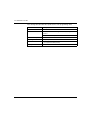
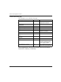
The following table lists RTP request block words:
Modbus
Address
Upper Byte
Lower Byte
Data Type
Attribute
45130
sub-index
toggle + length
unsigned 16
RW
45131
index (high data byte)
index (low data byte)
unsigned 16
RW
45132
data byte 2
data byte 1 (LSB)
unsigned 16
RW
45133
data byte 4 (MSB)
data byte 3
unsigned 16
RW
45134
toggle + CMD
Node ID
unsigned 16
RW
NOTE: The RTP request block is also presented in the manufacturer specific area of the
CANopen fieldbus as an object with a dedicated index of 0x4101 and sub-index 1 to 5
(data type = unsigned 16, attribute = RW).
The NIM performs range checking on the above bytes as follows:
index (high / low byte): 0x2000 to 0xFFFF for write; 0x1000 to 0xFFFF for read
z toggle + length: length = 1 to 4 bytes; the most significant bit contains the
toggle bit
z toggle + CMD: CMD = 1 to 0x0A (see the table Valid Commands, below); most
significant bit contains toggle bit
z Node ID: 1 to 32 and 127 (the NIM itself)
z
The toggle+CMD and toggle+length bytes are at either end of the RTP request
register block. The NIM processes the RTP request when the same value is set in
the respective toggle bits of these two bytes. The NIM processes the same RTP
block again only when both values have changed to a new identical value. We
recommend that you configure new matching values for the two toggle bytes
(toggle+CMD and toggle+length) only after you have constructed the RTP
request between them.
31004629 8/2009
125