1
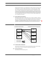
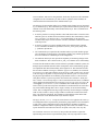
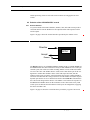
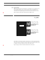
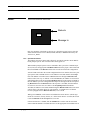
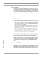
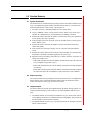
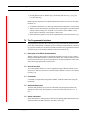
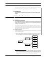
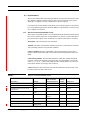
Created:April 15, 1996
Modified:January 15, 1997
Gemini
Controls
Group
Interface
Control
Document
ICD 1b — The Baseline Attribute/
Value Interface
Kim Gillies, Steve Wampler, Bret Goodrich
gscg.grp.024/05
This report defines the software interface comprising the
Attribute/Value interface in EPICS-based principal systems.
1.0 Introduction
1.1 Purpose
The baseline Gemini principal systems interface is described in its entirety in [4]. This
ICD document specifies the implementation for the Attribute/Value interface on an
EPICS-based principal system. Details of the upper layers of the command flow
between principal systems can be found in ICD 1a[5].
This document also describes the mechanism by which non-EPICS based principal systems report action responses using access to EPICS.
In detail this document:
1. Indicates the nature and behavior of the software interface.
2. Describes the EPICS support provided for this interface.
3. Provides an example implementation of this interface.
1.2 Scope
This document defines the implementation of the software interface provided for
EPICS-based principal systems and how to use this interface. This document defines the
software that is provided by the Gemini Project Office that allows a Principal System
Agent to transmit commands to an EPICS-based system.. Additionally, it provides a
sample implementation of an EPICS database that presents this interface.
This document does not address the command interface between principal systems not
involving EPICS. This information is found in [5].
ICD 1b — The Baseline Attribute/Value Interface
gscg.grp.024/05
1 of 26
Introduction
1.3 Applicable Documents
[1]
[2]
[3]
[4]
[5]
[6]
[7]
[8]
[9]
[10]
[11]
[12]
[13]
[14]
[15]
[16]
[17]
[18]
SPE-C-G0037, Software Design Description, Gemini 8m Telescope Project.
SPE-I-G0009, Software Programming Standards, Gemini 8m Telescopes Project.
GSCG.grp.005, Gemini System Interfaces, Gemini 8m Telescope Project.
GSCG.grp.006, Overview of System Interfaces, Gemini 8m Telescope Project.
GSCG.kkg.009, ICD 1a - The System Command Interface, Gemini 8m Telescopes Project.
GSCG.grp.013, ICD 2 - System Status and Alarm Interfaces, Gemini 8m Telescopes Project.
gscg.grp.025, ICD 16 — The Parameter Definition Format, Steve Wampler, Gemini 8m Telescopes Project.
GSCG.kkg.005, Baseline Major Systems Interface, Version 003, 28/6/94, Gemini
8m Telescope Project.
GSCG.kkg.002, OCS Behavioral Interface Model Report, Version 001, 23/6/94,
Gemini 8m Telescope Project.
GSCG.grp.001, A Report on the Interface Model Issues, Gemini 8m Telescope
Project.
WHT ADAM/EPICS INTERFACE, Version 0.2, Paul Martin, Chris Mayer, Phillip
Taylor, 27 July, 1994. Available from the authors.
The Virtual Telescope Interface, Jeremy Bailey, UKIRT System Note 6.3, 8
November, 1991.
Channel Access Reference Manual, Jeffrey O. Hill, EPICS Group, Los Alamos
National Laboratory.
Interprocess Message Passing (IMP) System, Keith Shortridge, Anglo-Australian
Observatory, DRAMA Software Report 8, Version 0.8, 19 April, 1994.
Self-defining Data System (SDS), Jeremy Bailey, Anglo-Australian Observatory,
Version 1.2, 9 September, 1992.
GSCG.grp.016, Glossary for the Gemini Software, Gemini 8m Telescopes.
EPICS Input/Output Controller Record Reference Manual, J.B. Anderson, M.R.
Kraimer, December, 1994.
GSCG.bdg.0004, Gemini Record Reference Manual, Bret Goodrich.
[19] cics_smb_027, Guide to the CICS Prototype, Steven M. Beard
[20] tcs_pbt_001, ICD 3.1/1.1.11 — OCS/TCS Command and Status Interface, Philip
Taylor, Royal Greenwich Observatory.
[21] cics_smb_013, “ICD 1.9%/3.1 — The OCS/CICS Interface”, Steven Beard,
Royal Observatory Edinburgh.
[22] gscg.sbw.060, “Implementation Models for the TCS/Subsystem Interfaces”, Steve
Wampler, Gemini 8m Telescopes Project.
[23] EPICS: IOC Application Developers Guide, Los Alamos National Laboratory.
[24] EPICS State Notation Language and Run-time Sequencer Users Guide, Andy
Kozubal, Los Alamos National Laboratory
2 of 26
gscg.grp.024/05
ICD 1b — The Baseline Attribute/Value Interface
Introduction
[25] EPICS Alarm Handler User’s Guide, Martin Kraimer, Ben-Chin K. Cha, Mark
Anderson, Janet Anderson, September, 19, 1991, Los Alamos National Laboratory.
[26] EPICS Alarm Configuration Tool and Alarm Handler User Interface System
Requirements Definition (DRAFT), Janet Anderson, Ben Chin-Cha, August 30,
1993. Los Alamos National Laboratory.
[27] EPICS Display Manager User’s Guide, Los Alamos National Laboratory.
[28] EPICS Archiving Reference Manual (DRAFT), Roger Cole, Los Alamos
National Laboratory. [N.B. This document is in preparation. The Gemini project
has a draft copy. Contact the author for up to date information].
[29] CAPFAST Electronic Circuit Design CAE User’s Manual, Phase Three Logic
Inc.., Beaverton, Oregon.
[30]
1.4 Abbreviations and Acronyms
CAD
Command Action Directive record
CAR
Command Action Response record
CIO
Command Input/Output
DHS
Data Handling System
EPICS
Experimental Physics and Industrial Control System
GCS
Gemini Control System
ICD
Interface Control Document
IMP
Interprocess Message Passing system
OCS
Observatory Control System
PSBI
principal Systems Baseline Interface
SDD
Software Design Description
SDS
Self-Defining Data System
SIR
Status Information Report record.
TBP
To Be Provided
VSM
Virtual System Interface Model. The Virtual Telescope Interface
model (see [12]), generalized to arbitrary systems.
1.5 Glossary
Additional glossary information is available in [16].
Action — When a system is sent a command, it responds with some behavior. This
behavior is the action associated with that command. Acceptance of the command by
the system results in the initiation of the action. A single action may be composed of
multiple subsystem actions.
ICD 1b — The Baseline Attribute/Value Interface
gscg.grp.024/05
3 of 26
Overview
Action Completion — An action that is initiated by some command is considered complete when the target system has either achieved the state described by the command,
or is incapable of doing so for some reason (typically an error). Action completion is
distinct from any status information that might also be associated with the mechanisms performing the action.
Attribute — An attribute is a textual description of some part of a Gemini based hardware or software system. An attribute has an associated value.
Attribute Group — A system may group several related attributes into an attribute
group. Attribute groups are used to identify arguments to a command within that system or to associate attributes whose values are interdependent. It is possible for an
attribute group to be empty or to contain a single attribute. The current implementation assumes that every attribute exists within some attribute group.
Command Completion — Commands are considered as ‘complete’ after they have
been recognized and accepted or rejected by a principal system. This is analogous to
the concept of command completion in the Virtual Telescope model[12], where
actions are assumed to be instantaneous.
Configuration — A set of attributes and their associated values describing the differences needed to move the system from one state to another state.
Principal System — At the highest level in the GCS software decomposition, the software system is divided into four kinds of software systems called principal systems.
The four types are called: the Data Handling System, the Observatory Control System, the Telescope Control System, and the Instrument Control System. There may be
up to four concurrently executing Instrument Control Systems.
System Configuration — The portion of a configuration that is unique to a single system is called a system configuration.
Systems Interface — The principal systems within the GCS software design interact
with one another through the Systems Interface.
Value — The value is the data associated with a particular attribute.
1.6 Stylistic Conventions
Program text is shown in the Courier typeface.
2.0 Overview
The Software Design Description [1], describes the Gemini Control System software.
This document assumes familiarity with the software design and terms defined in the
design document. Documents [5], [8] and [9] can help relate the contents of this document to the overall software design.
4 of 26
gscg.grp.024/05
ICD 1b — The Baseline Attribute/Value Interface
Overview
Principal Systems transmit system configurations to other principal systems along with
action directives. The most common action directive is to apply the system configuration, at which point the target principal must decide if the new configuration is valid
and, if so, initiate an internal action to match that configuration. The target principal system must report when that internal action has completed, whether the action is successful or not. The target principal system should also report the progress of subsystems that
are involved in that action. The intent is to allow the concurrent and independent direction of independent subsystems.
2.1 System Hardware Architecture
The Gemini Control System is a distributed system executing on machines of different
types and operating systems. The real-time principal systems software executing in the
Telescope Control System and the facility Instrument Control Systems is based on a
combination of VxWorks and EPICS. Figure 1 shows how the principal systems would
typically be distributed between VxWorks/EPICS systems and Unix-based systems.
FIGURE 1.
Typical Gemini Principal System ICD 1b Control Flows
Unix-Based Principal Systems
OCS
(Unix-based)
DHS
(Unix-based)
ICS(2)
(nonconforming)
Action Directive:
Action Response:
VxWorks/EPICS-based Principal Systems
TCS
(EPICS-based)
ICS(1)
(EPICS-based)
ICS(3)
(EPICS-based)
ICS(4)
(EPICS-based)
2.2 Communication Architecture
This interface document describes software interfaces that are entirely within a single
machine; therefore, there is no hardware communication architecture.
2.2.1
Events and Responses
The interface acts on the following events:
ICD 1b — The Baseline Attribute/Value Interface
gscg.grp.024/05
5 of 26
Behavior
TABLE 1.
Events and Responses
Events
Responses
Attributes are set
The receiving system does nothing at this time
except store the attribute values.
An attribute group is marked
The receiving system records that this attribute
group contains attributes that are involved in
the new action. (i.e. part of the configuration)
An action is started
The receiving system validates the action and
attributes, reports ACCEPT or not, and initiates the action if the action is accepted. If the
action is not accepted, the system reports
REJECT and provides a message describing
the reason for REJECTing the action.
An action is stopped
The receiving system stops the action and
reports that information. A stop event implies
an early termination of the action with no
unusual conditions. Not all actions can be
stopped.
An action produces status information during
operation
The system provides that status information in
two forms, as direct status information on its
components or as action response messages
reporting the progress on performing the
requested action. This may include reporting
the progress of subsystems involved in the
action.
An action completes
The system notifies other systems that the
action has completed through an action
response message.
An attribute group is reset
That action is reset to a known state that would
result in the attributes associated with that
action being ignored until the next mark.
(i.e. removed from the configuration)
3.0 Behavior
The behavior is based upon an Action Model for command flow as described in
ICD 1a[5].
4.0 Implementation Overview
The Command Layer must be able to tell when commands are completed and must pass
completion information back to the source principal system. The SDD OCS chapters
describe the command completion information that includes a BUSY/DONE attribute,
6 of 26
gscg.grp.024/05
ICD 1b — The Baseline Attribute/Value Interface
Implementation Overview
an error attribute, and an error string attribute, which must be present in all commands/
configurations. The Command Layer must be able to synthesize these attributes for
commands from the information in the Attribute/Value Layer.
The archetype for the Attribute/Value layer is EPICS and its Channel Access functionality (see document [13]). The Command Layer requires that non-EPICS systems provide
Channel Access-like functionality at the Attribute/Value Layer. This is summarized in
the following items.
• It must be possible to set and get attribute value fields based on the text names of the
attributes (process variables and record fields in EPICS). This functionality is based
on ca_put and ca_get. However, the ca_search functionality is not part of the
Attribute/Value Layer software interface. If needed, it should be within the Attribute/
Value layer itself.
• It must be possible to set and get attribute fields in the method used by Channel
Access. Attributes and fields are specified as: attribute_name.[field_name] where
[...] indicates optional text.
• The Command Layer requires that the Attribute/Value Layer mark attribute groups
once all attributes in that group have been made available. Only attribute groups that
have been marked are considered part of the configuration.
• The Attribute/Value layer must provide the capability of monitoring changes in the
fields of attributes. This is based on the ca_add_event Channel Access functionality.
To ensure that the Attribute/Value software interface is plausible on EPICS systems, the
Principal System Baseline Interface makes assumptions on how Work Package groups
will implement their EPICS functionality at the highest level. This document assumes
that several new EPICS record types, called the Apply Action (APPLY), the Command
Action Directive (CAD) and Command Action Response (CAR) records, are to be used
as the first stage of all public record processing on an EPICS system. A CAD record is
the physical representation for an attribute group and there will be a CAD record for
each public function a system can perform. For instance there could be a “dome position” CAD or a “next telescope target” CAD. Associated with each CAD is a CAR that
can be monitored to determine the action response. Typically, this will be the same CAR,
called applyC, for all CADs in a system. In addition, other CARs may be associated
with a CAD to provide action response information on mechanisms that are involved in
any action initiated through that CAD. A single CAR may be associated with many
CADs. Thus a configuration involving a single CAD may result in changes to multiple
CAR records, but there is always a single CAR record that can be monitored to determine if an action has completed. The assumption of the APPLY/CAD/CAR records
makes discussion of the Attribute/Value Layer interface simpler.
The Apply Record (APPLY) accepts an action directive to be applied to the entire system configuration that is represented by the attribute groups that have been transmitted
as part of the system configuration. This record handles the validation of attributes
within the configuration and the sequencing among CAD records. The APPLY record
reports whether the action directive has been accepted or not (and, if not, why not).
The Command Action Directive Record (CAD) provides the interface required for
implementing action directives upon attribute groups. The only output from a CAD
ICD 1b — The Baseline Attribute/Value Interface
gscg.grp.024/05
7 of 26
Implementation Overview
record that is visible outside the EPICS database is whether or not the action directive
applied to that attribute group has been accepted or not (and, if not, why not). In practice, this even this information is not needed outside the EPICS database, since it is
reflected in the output from the APPLY record.
The Command Action Response Record (CAR) is the record used in the Action
Response Database to provide action response information from a principal system to
other systems.
The mapping of attribute names to EPICS records and the checking of command parameters is simplified when an EPICS system implements the command functionality as
APPLY/CAD/CAR records.
4.1 General Comments on the CAD, CAR, and APPLY Records
First, it must be understood that these records are just part of the chain involved in the
translation of commands from a principal system into an EPICS database driven system.
It provides specific behavior that is intended to meet specific functional requirements.
The entire chain of control flow must be considered when illustrating the behavior of
CAD records.
CAD records provide ‘synchronization’ points between the database-driven control
model found in EPICS and the model present in the higher-level systems. They allow an
application in one of these higher-level systems to establish a consistent set of desired
conditions (an ‘attribute group’) before provoking action on those attributes by the
EPICS system. CAD records also report ‘command completion’ based on the virtual
system model. That is, the command is considered completed as soon as it has been
accepted or rejected by the subsystem, and the CAD record provides this response
immediately after verifying the command. A CAD is considered part of the current system configuration only after it has been marked as such by the configuration layer of the
interface.
While CAD records provide some feedback information useful in a command model,
they should not be considered ‘command processors’ - that functionality is found in the
Command Layer Servers (CLS) that are layered on top of APPPLY, CAD, and CAR
records.
Furthermore, CAR records make no attempt to impose a particular meaning to the concept of ‘action completion’. The Gemini control system is predicated on the
concept of ‘action completion’, where an action completes when all activity associated
with that action is finished. Determining this action completion is the responsibility of
the EPICS database ‘below’ the CAR record. The CAR record merely serves as a conduit to provide information on the action status from the EPICS database to the CLS and
other systems.
Within an EPICS database, there is always one special record, called the APPLY record.
This record is responsible verifying that the attributes in the current set of attributes are
valid within the current context and then for starting the actions associated with those
attributes. The CLS always initiates actions in other principal systems using this record
8 of 26
gscg.grp.024/05
ICD 1b — The Baseline Attribute/Value Interface
Implementation Overview
and the processing of this record results in action directives being applied to CAD
records.
4.2 Behavior of the CAD/CAR/APPLY records
4.2.1
External Interface
To systems outside of the EPICS database, APPLY, CAD ,and CAR records provide a
consistent interface into the database for all requested actions and responses to those
action requests.
Figure 2 on page 9 shows the external interfaces provided by the APPLY record.
FIGURE 2.
External Interfaces for the APPLY record
Directive
APPLY
Accept
Reason
The Directive may be one of MARK, PRESET, START, STOP, or CLEAR. MARK sets
the MARK field on all CAD records (this is rarely needed). PRESET is never sent by an
external system, but will be used when cascading APPLY records. STOP and CLEAR
are sent to all CADs. The START directive results in all CADs that are part of the configuration to validate their attribute values. If all CADs report ACCEPT, then the
APPLY record reports accepts the action and initiates the action by sending START to
all CADs. Note that while all CADs get directives from the APPLY record, the response
depends upon whether or not a CAD has been marked. The Client ID is transmitted to
the CAD records along with the directive. The APPLY record collects the responses to
the PRESET and START directives that it transmits to the CAD records. If any CAD
record rejects its attributes then the APPLY record rejects the configuration, supplying
the reason from that CAD.
Figure 3 on page 10 shows the external interfaces provided by a typical CAD record.
ICD 1b — The Baseline Attribute/Value Interface
gscg.grp.024/05
9 of 26
Implementation Overview
FIGURE 3.
External Interfaces for CAD records
Directive
Client ID
Attribute Values
CAD
Simulate
Accept
Reason
‘Directive’ may be one of MARK, PRESET, START, STOP, or CLEAR. (Of these, only
MARK and CLEAR are sent from other systems, PRESET, START, and STOP are set
by the APPLY record processing. Although STOP might be sent from another system.)
After an action is requested, the Accept output simply informs the requester whether the
action can be performed or not. The Reason informs the requesting application why a
requested action has been rejected. Reasons include:
• an invalid value was provided for some attribute (details of the specific argument are
included in the reason)
• the action specific to this request is busy and is one that may not be altered while in
progress
• the action can not be performed at this time (details included in the reason)
• security violation (application/user not permitted to request action)
‘Simulate’ is used to place the underlying EPICS database into the appropriate simulation mode. Simulate may be one of NONE, VSM, FAST, or FULL. Client ID is used by
the OCS to perform command tracking.
10 of 26
gscg.grp.024/05
ICD 1b — The Baseline Attribute/Value Interface
Implementation Overview
It is important to note that directives do not correspond to system commands. Commands are embodied by the individual CAD records. For example, there might be CAD
records for MOVE, OFFSET, etc. Directives instruct the EPICS system to act in some
manner on the command that the specific CAD record embodies.
There may be additional fields accessible for special purposes, such as one that might be
used to identify this CAD as one that has been preset, but these are not considered part
of the interface available to the ‘typical’ application.
There are different versions of the CAD record that differ only in the number of
attributes that can be transmitted. Developers should choose the most appropriatelysized CAD record for their purposes. These CAD records are named:
•
•
•
•
CAD - The ‘normal’ size for 2 or fewer attributes
CAD4 - Slightly larger size for 4 or fewer attributes
CAD8 - Moderately sized for 8 or fewer attributes
CAD20 - Big size for 20 or fewer attributes
It is important to note that all responses available to an application issuing an action
request are available immediately. That is, these responses do not provide information
on the status of a valid request during operation on the action. That is the role of the
CAR records.
Figure 4 shows the external interfaces for the CAR record.
FIGURE 4.
External interface for CAR records
Status
CAR
Message
The Status may be one of IDLE, BUSY, PAUSED, or ERROR, where the Message provides information about the nature of the Status response. Appended to the Status value
is the current CL_DATA value (the client id provided to the CAD that initiated the current action).
As with the CAD record, there may be additional fields that are not considered part of
the ‘typical’ external interface.
ICD 1b — The Baseline Attribute/Value Interface
gscg.grp.024/05
11 of 26
Implementation Overview
4.2.2
Internal Interface
While the external interfaces described above are intended for use by applications ‘outside’ the EPICS database, these records also include connections intended for use
within EPICS when implementing the desired actions associated with these records.
Figure 5 on page 12 shows these connections for the APPLY record.
FIGURE 5.
‘Internal’ Connections for the APPLY record.
CL_DATA
APPLY
Directive Out
Client ID Out
Accept/Reject In
Reason In
Directive Out
Client ID Out
Accept/Reject In
Reason In
Each APPLY record contains a number of identical sets of ‘internal’ input/output links,
where each set may be connected to a specific CAD record or to another APPLY record
(so APPLY records may be linked to reference many CAD records).
Figure 6 on page 13 shows the internal connections for a CAD record.
12 of 26
gscg.grp.024/05
ICD 1b — The Baseline Attribute/Value Interface
Implementation Overview
FIGURE 6.
‘Internal’ Connections for CAD records
CAD
START
STOP
MARK
PRESET
CLEAR
CL_DATA
Attribute Values Out
Simulate Out
The START field enables EPICS forward processing in response to a valid START
directive, PRESET and CLEAR may be used to initiate related actions within the
EPICS database, and STOP and MARK imply their obvious meanings. The Simulate
Out field is set when the particular action is to be simulated instead of actually performed. The CL_DATA field is a copy of the Client ID input field.
Each Attribute Values Out line is actually represented in the implementation by a pair
of output lines, one for a value for that attribute and the other for a link field for that
attribute. Typically only one line in each pair will by used by a particular CAD record.
Similarly, the CAR record includes connections for obtaining status information as a
result of EPICS database processing. These connections are shown in Figure 7 on
page 14.
ICD 1b — The Baseline Attribute/Value Interface
gscg.grp.024/05
13 of 26
Implementation Overview
FIGURE 7.
‘Internal’ Connections for CAR records
Status In
CAR
Message In
Here, the meanings of the fields are obvious. It is important to note, however, that the
Status In field consists of one of BUSY, DONE, PAUSE, or ERROR followed by the
value for CL_DATA.
4.2.3
Operational behavior
The APPLY, CAD, and CAR records collectively provide the interface into an EPICSbased principal system. This section describes their typical use.
When another principal system issues a command to this system, the Command Layer
Server(CLS) sets the appropriate Attribute Value fields in the proper CAD records and
then sends MARK to the Directive fields of the records involved in the configuration.
After all CADs involved in the current configuration have been marked, the source principal system sends a START directive to the APPLY record and monitors the Accept
field. The APPLY record then issues a PRESET directive through its Directive Out
links (in order, from ‘top’ to ‘bottom’. After each PRESET, the APPLY record waits for
acknowledgement on the associated Accept/Reject In field. If the response is REJECT,
then the APPLY rejects the configuration and copies the message from the corresponding Reason In field to the Reason field. If the response is ACCEPT, then the APPLY
record moves on to the next set of links. If all Accept/Reject In fields indicate
ACCEPT, the APPLY record sends START through its Directive Out links (in the same
order as above). The other directives work similarly - a CLEAR sent to an APPLY
record is propagated out its Directive Out links, as is a STOP.
When given a PRESET, each CAD record validates the action directive (checks arguments for correctness, security checks, etc.). If the action directive is invalid, the reason
is stored in Reason and the Accept field is set to NO.
If the action directive is START, then the START link is used to start the associated
action within the database. The STOP directive sets the appropriate forward link field. A
14 of 26
gscg.grp.024/05
ICD 1b — The Baseline Attribute/Value Interface
Implementation Overview
STOP directive must safely halt any related actions, resulting in the associated CAR
records for those actions entering the done state.
The CLEAR directive puts the record into a state where a subsequent START command
will not result in it being processed (i.e. unmarked). In the case of the APPLY record,
this means that all CAD records are unmarked..
The EPICS database ‘below’ the CAD record is responsible for properly maintaining
the values in the CAR records for initiated actions..
If an action completes successfully, the Status In field should be set to DONE. If the
action cannot complete successfully, the reason for the failure is placed into the Message In field and the Status In field is set to ERROR. Regardless of the status, the message should reflect whether or not the action was a simulated action.
4.3 Functionality Provided by APPLY/CAD/CAR Records
The design of the APPLY, CAD, and CAR records provides a great deal of operational
flexibility. This section presents some of the ways in which these records may used by
applications.
4.3.1
Virtual System Modelling
If there is a need to implement an application using the virtual system model, then the
Accept field provides the ‘instantaneous’ feedback on the success/failure of the Virtual
System. It also provides a mechanism for extending the concepts of the Virtual System
Model to other systems.
4.3.2
Real Telescope Modelling
On the other hand, most of the OCS recipes depend on the completion of actions having
actually occurred (for sequencing). The CAR associated with the APPLY record may be
monitored, once the Accept status has been set in the corresponding CAD record, to
determine when this action has completed and whether or not the action was successful.
4.3.3
System monitoring
Monitoring of the system can be accomplished through the CAR records (and other status records). For example, all graphical interfaces that include a button for Telescope
Offset could show the status of actions that occur as a result of initiating an Offset command by simply monitoring the appropriate CAR records when any application initiates
an offset.
4.3.4
Non-EPICS system control
Non-EPICS-based systems report action status using CAR records as well, through the
Action Response Database found in the OCS[5]. Thus applications do not need to be
concerned with whether or not a action is being performed by an EPICS system or not.
(Only the Command Layer Servers need be concerned with this information.) For example, all GUIs could monitor CAR records for action response information, regardless of
the source.
ICD 1b — The Baseline Attribute/Value Interface
gscg.grp.024/05
15 of 26
Example EPICS Database
4.3.5
Action behavior
Since the action is performed by the EPICS database ‘below’ the APPLY and CAD
records, determining completion is independent of CAD/CAR record processing and
can be defined as best appropriate for each specific action. For example, some actions
may be ‘overwritable’ with new attribute values (such as changing the final position of a
slew that is underway), while other actions might ‘queue-up’ for serial processing. It is
the responsibility of the database developers to provide the appropriate functionality.
4.3.6
Selective Simulation
The CAD Simulate Out field provides a mechanism by which individual actions may
be simulated within a larger EPICS database.
4.4 Simulation Modes
The four values that may be set in a CAD record provide a means of placing the underlying system into the following simuluation modes:
• VSM - The system is to operate in ‘Virtual System Mode’. Here the CAD record
verifies attribute values and accepts or rejects the commands, but does not pass any
information on to the rest of the database.
• FAST - The system’s CAD/CAR and SIR records are enabled, and some internal
computations may be performed, but response times are not realistic. Responses
from subsystems are simulated.
• FULL - Full simulation, CAD, CAR, and SIR records enabled and the system
respones will take realistic time. The system itself performs all internal computations, but responses from subsystems are simulated with realistic timings.
• NONE - There is no simulation. The system is to operate normally.
These modes are to be provided as the system is developed in the order shown here. The
VSM mode provides a way for principal systems to check command flows and completeness. FAST mode allows for the testing of interfaces in an integrated environment,
while FULL permits the testing of a system without its subsystems operating.
Normally the Simulate fields in a system are linked so that a single process variable is
available to put the entire system into a consistent simulation mode, even though the
mechanism supports putting different parts of the system into different simulation
modes.
5.0 Example EPICS Database
An example EPICS database that illustrates the usage of the Apply, CAD, CAR, and
SIR records is given in the Core Instrument Control System documentation [19]. This
database describes a simple instrument that accepts commands through a Apply and
CAD record interface and presents the action results through CAR and SIR records.
16 of 26
gscg.grp.024/05
ICD 1b — The Baseline Attribute/Value Interface
Detailed Behavior
6.0 Detailed Behavior
6.1 System Commands
The transmission of commands between principal systems at the EPICS channel access
level is accomplished using the APPLY, Command Action Directive (CAD) and Command Action Response (CAR) records. The procedure is:
1. Set all the necessary CAD input parameters to the required values.
2. Assert a “PRESET” directive on the system’s master APPLY record. (This step is
3.
4.
5.
6.
7.
8.
optional, as a START directive will automatically use PRESET if needed).
Examine the status returned by the APPLY record to check all the given parameters
are acceptable. (This step is optional).
If the parameters have been accepted, assert the “START” directive on the system’s
master APPLY record.
Examine the status returned by the APPLY record to check all the actions have
started successfully.
If the actions have started successfully, note the “client ID” field of the APPLY
record.
Monitor the CAR record associated with the CAD records that were activated (this
information is available in the PDF supplied by the system, [20]).
When the CAR record changes from “BUSY” to “IDLE”, check the “client ID” contained in the CAR record:
—If the CAR client ID is less than the APPLY client ID noted at step 6 the action has
not yet completed, so go back to step 7.
—If the CAR client ID is the same as the APPLY client ID the action has completed
as requested.
—If the CAR client ID is greater than the APPLY client ID the action has completed
but some other client has overridden the request with a more recent command.
6.2 Status reporting
The receipt of status between principal systems at the real-time level is accomplished by
EPICS channel access of Status Information (SIR) records. The behaviour of these
records is described in ICD/2, [6]. See Section 6.3 below.
6.3 Implementation
The basic interface has already been implemented by the EPICS develop group at Los
Alamos National Laboratory in New Mexico. The following EPICS utilities may be
used:
• The EPICS Channel Access transport mechanism (CA), [23], which can be used to
access database parameters on VxWorks machines running EPICS. This provides all
the functionality required for these interfaces.
• The EPICS Database System ([17], [23] and [24]) functions as the target-side termination of these interfaces.
ICD 1b — The Baseline Attribute/Value Interface
gscg.grp.024/05
17 of 26
The Programmatic Interface
• Existing EPICS tools for database query, monitoring and control (e.g. [25], [26],
[27], [28] and [29]).
Besides the basic channel access implementation this interface also relies on the implementation of:
• Command Action Directive (CAD) and Command Action Response (CAR) records.
• APPLY records, which connect associated CAD records together in a predetermined
order and which manages the “client ID”. The TCS has a master APPLY record
which connects ultimately to all its public CAD records.
• Status Information (SIR) records, whose implementation is described in ICD/2, [6].
7.0 The Programmatic Interface
The programmatic interface derives directly from [5], and models the Attribute/Value
Layer (AVL) functionality. Comments specific to an EPICS implementation of the AVL
are given here. Readers are assumed to be familiar with the AVL programmatic interface
described in [5] as well as EPICS database construction methods [17].
7.1 Description of an EPICS Implementation
APPLY, CAD and CAR records are implemented as EPICS records. Access to them is
through standard EPICS database construction methods. The validate parameters suboutine associated with each CAD record should convert and check parameters values from
ASCII to the appropriate EPICS internal value.
7.2 General Structure
Access through this interface is to be accomplished using the EPICS Channel Access
system to set, monitor, and retrieve fields from EPICS database records, as described in
reference [13].
7.3 Commands
Commands are implemented using EPICS APPLY, CAD and CAR records using the
mechanism.
7.4 Attributes/Parameters
Attributes and parameters are passed for commands using the argument field of the
appropriate CAD record. The arguments are listed in an ICD such as ICD 3.1/1.1.11,
[21].
7.5 Status Information
Status information is exchanged across this interface through public EPICS Status and
Information Records (SIR), which are described in ICD/2, [6].
18 of 26
gscg.grp.024/05
ICD 1b — The Baseline Attribute/Value Interface
Software/Control Function Interface
The status information provided by the ICS and TCS should be declared in a Parameter
Definition Format (PDF) (e.g. [21] and [20]), as specified in ICD/16, [7].
7.6 Data Structures
The data structures transmitted across this interface are the values for EPICS process
variables.
8.0 Software/Control Function Interface
8.1 Overview
8.1.1
Communications infrastructure
The commands and responses are implemented using the facilities of EPICS and in particular use the services provided by Channel Access (CA). The full list of facilities provided by CA are described in [13].
The commands and responses themselves will be implemented using the Command
Action Directive (CAD) and Command Action Response (CAR) records developed by
the Gemini Project Office. Public status information will be held in Status and Information (SIR) records, as described in ICD/2, [6].
8.1.2
Software architecture
A context diagram for the OCS to ICS interface may be found in ICD/1a, [5]. The interface uses the following rules:
1. All the CAD records in a principal system which the OCS needs access to are con-
nected to an APPLY record or hierarchical structure of APPLY records like this1.
CAD
APPLY
CAD
CAD
APPLY
CAD
APPLY
CAD
CAD
1. The OUTA, OUTB,... and OCLA, OCLB,... fields of the APPLY record are connected respectively to the DIR and ICID fields of each CAD record. The VAL and MESS fields of the CAD
record are connected to the INPA, INPB,... and INMA, INMB,... fields of the APPLY record,
enabling the APPLY record to sense the status returned by all the CAD records.
ICD 1b — The Baseline Attribute/Value Interface
gscg.grp.024/05
19 of 26
Software/Control Function Interface
The database should be structured in such a way that a single APPLY record can
trigger all the CAD records. This structure is necessary so the OCS can trigger a
reconfiguration of the principal system by modifying its list of attributes and values
and the activating the top level APPLY record.
8.2 Behaviour
In general, the OCS can send commands to a principal system at any time, and the commands can come in any order. The APPLY record is used so a principal system can
ensure that particular commands are executed in the correct order even if the OCS activates them in a different order. The preset and accept/reject mechanism described in this
section can be used to ensure that commands are not executed at inappropriate times or
with inappropriate parameters.
All the commands in an OCS to principal system interface are “one off” commands in
the terminology of reference [22]. “one-off” commands are those where the principal
system goes off and does something based on a fixed set of parameters. The associated
CAR record goes “BUSY” while the action triggered by the command is in progress and
“IDLE” when it has finished.
The other type of command is “continuous”, in which a system strives to match a continuous stream of demands. This type of command is not used by the OCS.
8.2.1
One-off command behaviour
The general scenario for a one-off command is:
1. Either:
—The desired arguments are written to the argument input fields of the CAD record
(i.e. the A, B, C,... fields); or
—The MARK directive is asserted on the CAD record’s DIR field.
Each time a CAD record receives a directive it reads a “client ID” from its ICID
field.
2. The PRESET directive is asserted on the CAD record’s DIR field. The CAD record
then checks its input arguments are acceptable. If they are acceptable it returns a
CAD_ACCEPT value in its VAL field. If they are not acceptable it returns a
CAD_REJECT value in its VAL field and a message describing the reason for failure
in the MESS field. (The effect of the MARK and PRESET directives can be cancelled by means of the CLEAR directive).
The CAD record can also return CAD_REJECT if the execution of the command is
not possible at this time.
3. The START directive is asserted on the CAD record’s DIR field. The CAD record
checks whether it can start the action associated with the command. If the START is
accepted it returns a CAD_ACCEPT value in its VAL field and starts the action associated with the command. If the START is rejected it returns a CAD_REJECT value
in its VAL field and a message describing the reason for failure in the MESS field.
If step 2 is missed, the PRESET directive will automatically be executed before the
START directive.
20 of 26
gscg.grp.024/05
ICD 1b — The Baseline Attribute/Value Interface
Software/Control Function Interface
4. The progress of the action started by the command is reported back through its cor-
responding CAR record. The CAR record can be in one of the following states:
—UNAVAILABLE — The action is currently unavailable;
—IDLE — The action is not executing;
—BUSY — The action is executing;
—PAUSE — The action has been paused;
—ERR — The action has failed.
The CAR record also records the client ID of the most recent directive to affect the
action.
5. Then one of the following things can happen:
—The action completes in its own time, in which case the CAR record changes state
as indicated in step 4; or
—The STOP directive is asserted on the CAD record’s DIR field. The CAD record
checks whether it can stop the action associated with the command. If the STOP is
accepted it returns a CAD_ACCEPT value in its VAL field and stops the action
associated with the command. If the STOP is rejected it returns a CAD_REJECT
value in its VAL field and a message describing the reason for failure in the MESS
field
The CAR record changes state as indicated in step 4.
The OCS normally sets a CAD record’s arguments but uses the APPLY record to deliver
the appropriate directives (as described in the next section).
8.2.2
Use of the APPLY record
The APPLY record allows a principal system to receive commands which change its
configuration in any order but only to execute those commands in the correct order.
When the OCS wishes to change a principal system’s configuration it goes through the
following sequence:
1. It updates all the CAD input parameters (i.e. A, B, C,...) which need to change.
Changing these inputs causes all the relevant CADs to be marked (as indicated by
the MARK field).
2. It asserts a PRESET directive on the top level APPLY record. The APPLY record
makes up a new client ID, and the PRESET directive is forwarded to all the marked
CAD records, in the same order they are connected to the APPLY record. The
marked CAD records then check that all their parameters are sensible and return an
ACCEPT or REJECT. The status returns from all the CADs are checked by the
APPLY record.
3. It is possible for the APPLY record to be connected to other kinds of EPICS record
than a CAD. For example, if complex checks are needed which involve cross refer-
ICD 1b — The Baseline Attribute/Value Interface
gscg.grp.024/05
21 of 26
Software/Control Function Interface
encing the parameters from several CAD records these checks could be done in a
subroutine record connected to the last link of the APPLY record, i.e.:
CAD
CAD
APPLY
SUB
4. If the APPLY record reports that all the CAD records returned ACCEPT, the OCS
then asserts the START directive on the top level APPLY record. This starts all the
marked CAD records in the same order they are connected to the APPLY record.
5. Note that the CAD records need to be connected to the APPLY record in the most
sensible order of operation.
8.2.3
Instrument response to the observe command
Efficient execution requires special considerations when instrument detector readout
times are considered. ICD 1a describes three status variables, PREP, ACK, and RDOUT,
which are used to efficiently sequence operations. The following figure shows how these
variables can be used along with various CAR records to overlap sequencing of successive observations..
22 of 26
gscg.grp.024/05
ICD 1b — The Baseline Attribute/Value Interface
Software/Control Function Interface
TABLE 2.
ICS actions when observations follow one another quickly and apply overlaps readout.
Observation 1
CARs
SIRs
Observation 2
apply observe prep acq rdout
config(apply)
config(observe)
config(apply)
config(observe)
CAR record BUSY
SIR record ON
In the figure the CAR records are assumed to be IDLE when not BUSY, and the SIR
records are OFF when not ON. Note that the observe CAR stays on for the duration of
each observation. Without the status records, the recipe controlling the observation
could not safely issue the second apply until the observe CAR went IDLE.
ICD 1b — The Baseline Attribute/Value Interface
gscg.grp.024/05
23 of 26
Software/Control Function Interface
8.3 Implementation
This section contains tables summarising the EPICS records used for the interface. Only
the compulsory EPICS records are listed. In their own ICD principal system groups
should give a complete list of the commands their system recognises.
It is assumed in all cases that the record names given in this document will be prefixed
by a string identifying the system when the database is implemented. See reference [2]
for a complete list of prefixes.
8.3.1
Sequence Command (CAD/CAR) records
The sequence commands in Table 3 are commands that all the Gemini principal systems
have to obey, and they follow the recommendations in reference [5]. All Gemini principal systems must recognise these commands. The columns of the table are as follows:
Description. A brief description of the command.
Attribute. The name of the attribute which the Observatory Control System associates
with a particular parameter of a particular command.
CAD record/field. The name of the EPICS CAD record (minus the system prefix)
together with the field in that CAD record associated with each parameter of the command.
CAD ordering number. The recommended order in which this command should be
executed. CAD records should be connected to their associated APPLY record in the
order 1, 2, 3, 4, 5, etc... CAD records within the same ordering number set can be connected to the APPLY record in any order in that set.
CAR record. The CAR record associated with the command. Note that several CAD
records may share the same CAR record.
TABLE 3.
Sequence command CAD/CAR records
Description
Attribute
Self test.
(none)a
modeb
CAD record/field
(instrument prefix +)
CAD
ordering
number
CAR record
test
1
testC
Initialise.
Simulation
init:a
2
initC
Find datum/reference point for all
mechanisms.
(none)a
datum
2
datumC
Reset to start-up state.
(none)a
reset
2
resetC
Apply the preset configuration.
(none)a
(Uses APPLY
record)
N/A
applyCc
Begin verifying.
(none)a
verify
5
verifyC
Stop verifying.
(none)a
endVerify
7
endVerifyC
Begin guiding.
Guiding modeb
guide:a
8
guideC
24 of 26
gscg.grp.024/05
ICD 1b — The Baseline Attribute/Value Interface
Debugging
TABLE 3.
Sequence command CAD/CAR records
CAD
ordering
number
CAR record
Description
Attribute
CAD record/field
(instrument prefix +)
Stop guiding.
(none)a
endGuide
9
endGuideC
Begin observation.
Data label
observe:a
10
observeC
Pause observation.
(none)a
pause
11
Continue observation.
(none)a
continue
12
Stop observation and keep data.
(none)a
stop
13
Abort current operation. Throw away
data.
(none)a
abort
13
Park all components.
(none)a
park
14
parkC
a. No arguments.
b. TBD
c. The “applyC” CAR record reports “BUSY” when any component in the instrument is busy.
9.0 Debugging
Since this software interface spans principal systems, issues related to testing and
debugging must be addressed. How does a principal system developer debug his system
independently of the OCS? How does the OCS develop independently of the principal
systems.
9.1 Principal Systems Development without the OCS
To ensure proper integration of systems, the engineering interfaces should use the same
set of process variables as will be used by the OCS to control the principal systems. This
would mean that the TCS and other principal systems functionality should be developed
in terms of APPLY, CAD, and CAR records from the start. The standard EPICS tools
will work just as well with APPLY, CAD, and CAR records as with the built-in record
types.
Because engineering screens are required to use the same interface as used by the OCS,
the principal systems developers do not immediately need the OCS functionality.
9.2 OCS Development Without Principal Systems
At some point, the OCS will need a simulator for each of the principal systems at the
Attribute/Value layer. This will be worked out at a later time.
ICD 1b — The Baseline Attribute/Value Interface
gscg.grp.024/05
25 of 26
Debugging
26 of 26
gscg.grp.024/05
ICD 1b — The Baseline Attribute/Value Interface