1
6. Troubleshooting Procedures
This section covers procedures for diagnosing and solving common problems with
GNIRS. Of course, it is our expectation that even "common" problems will be relatively
infrequent.
In general, there are two main ways of identifying problems. One is the diagnostic screens
described in section 6.1, which (among other things) monitor "system health" through a
variety of sensors and procedures. The health of the instrument or sub-system can be
categorized as "good", "warning" or "bad". Any state other than "good" should be
checked out; in some cases it is possible to continue operating effectively (especially
under warning conditions), but you should always verify the exact circumstance first.
The second indicator of problems is the science data stream. Always look at the data as
they are taken. The appendices to the User's Manual indicate what data should look like
for common configurations. If the actual observations look different, make sure that this
is consistent with random variation and does not have some other cause. In particular,
mechanism failures will show up first as night sky line spectra that do not match the
appendices or as excess (or deficient) background levels. Other things to look for are bad
images (possibly indicative of incorrect focus, excess flexure or guiding problems) and
excess noise (indicative of controller or grounding problems).
GNIRS Service & Calibration Manual
80
Section 6
6.1 Diagnostic Windows
The diagnostic windows for GNIRS are EPICS dm screens which can be used to monitor
and modify EPICS variables. Type nirsStart (script located in {BASE}/bin/solaris) to
start the top dm screen and the 4 console windows that are connected to the four vxWorks
machines associated with GNIRS. The diagnostic windows are an interface to the CAD,
CAR, APPLY records (see Software Manual for definitions and explanations), and also
show the current status of the system. Several display buttons will display a menu when
right clicking with the mouse. Some of these menus are dynamically loaded, so if the
system is rebooted, or the menu is reloaded after the dm screen is already displayed, the
right click menu won’t be updated. This is easily fixed by exiting the affected window
and re-displaying it from its parent window.
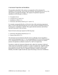
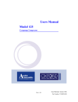
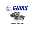
The window shown below is the top-level engineering window for GNIRS.
On this window, there are four buttons that correspond to the four major components of
the system.
1. Instrument Sequencer - The instrument sequencer controls the system most
like the OCS would. It communicates with all the other systems except for
the Wavefront Sensor.
2. Components Controller - The Components Controller monitors temperature
and pressure. It also controls the mechanisms, the detector and bench
temperature, and the cryo-motors.
GNIRS Service & Calibration Manual
81
Section 6
3. Detector Controller - The detector controller controls and monitors all
functions related to taking an image.
4. Wavefront Sensor – This displays the windows which control and monitor the
mechanisms in the Wavefront sensor.
5. Help - The help button will give a description of what all the colors on the
windows correspond to.
6. EXIT – Kills all dm windows
GNIRS Service & Calibration Manual
82
Section 6
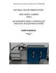
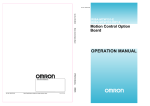
The Instrument Sequencer button on the main window displays the window shown
below.
This window shows the health and status of the system as a whole. It is also the location
where global commands can be run.
Important regions:
1. Apply – This controls the top level apply for the whole system. (right
click menu)
2. NIRS System Commands – Marks and starts the global CADs.
GNIRS Service & Calibration Manual
83
Section 6
3. Mechanism Control Commands – Change position of individual
mechanisms (does not include WFS mechanisms here). (below)
GNIRS Service & Calibration Manual
84
Section 6
4. Observation Control commands – Start stop and abort an observation here.
(below)
5. CC Screens – Main Component Controller window.
6. DC Screens – Main Detector Controller window.
7. NIRS SAD – System status information
8. Debugging – Set global or local debugging level.
9. Sequence Commands – guide, endGuide, verify and endVerify commands
10. Lookup Tables – Filter wheel tables
11. Temperature control – Detector temperature control and cryo cooler
operation
12. Temperatures – Temperature monitor.
GNIRS Service & Calibration Manual
85
Section 6
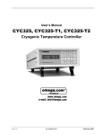
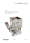
The next major component of the system is the Components Controller. This is where all
functions related to temperature pressure and mechanism position can be controlled or
monitored.
The buttons on the Components Controller window are listed below.
1. System Cad Records – This drop down menu contains the init, reboot, debug,
test diagnose and cryo Head CAD test windows.
2. Temperatures – This button starts one of three temperature monitor windows.
A right mouse click will drop down a menu for the user to pick one of the
windows. (below)
GNIRS Service & Calibration Manual
86
Section 6
3. Pressures – The pressure monitor window is displayed with this button. Only
two of the three sensors are actually in the system.
4. NoOps – This drop down menu contains the Gemini required CAD records
that have no function in the Components Controller.
5. System CAR Records – This displays a diagnostic window that shows the
state of all the CAR records in the system in a hierarchical format.
GNIRS Service & Calibration Manual
87
Section 6
6. Mechanisms – Starts a display window that will allow the user to run any of
the CAD diagnostic windows related to the ten mechanisms.
An example of one of these windows is shown below.
GNIRS Service & Calibration Manual
88
Section 6
7. Park – This performs a park command on all ten mechanisms.
8. Datum – This performs a datum command on all ten mechanisms.
9. Close – Close this window.
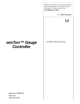
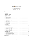
The Detector Controller engineering display is displayed below.
GNIRS Service & Calibration Manual
89
Section 6
Screen Regions
1. Image Setup – Not used with the DHS.
2. Observation Setup – Shows current state of observation parameters such as:
coadds, low noise reads, digital averages, number of pictures, and integration
time. In addition the integration time can be modified here. The obsSetup
CAD must be run for the change to take effect. (“Do Obs Setup” button, or
from “Observation Cntrl” in “Setup Commands” area.) The Observation can
be started, stopped or aborted here also.
3. uCode Waveform Generator Program – Displays the current uCode and path.
4. Overall Health – Displays health of the system.
5. Array Setup – Displays detector status such as the activation, uCode download
state, and bias level. (These values can be changed from the “Array Setup
Cntrl” or “Observation Cntrl” windows)
6. Array Voltages – Displays pertinent array voltages.
GNIRS Service & Calibration Manual
90
Section 6
7. Apply/Cad Test Screen – Right click to pull down a menu that allows the user
to choose one of the diagnostic CAD windows.
8. View Errors – Displays most of the APPLY, CAD, and CAR error status and
messages.
9. Clear Errors – This button clears the errors in all of the APPLY, CAD, and
CAR records in the Detector Controller.
10. Additional Screens – Right pulls down a menu that has a list of useful
windows.
11. Raw HouseKeeping – Two windows that show the value of every monitored
voltage in the system.
12. Setup Commands – Bring up windows that allow the user to setup all the
necessary parameters in the Detector Controller.
Array Setup Cntrl – Download ucode, and set array voltages.
Observation Cntrl - Set array activation, digital averages, co-adds, number of
pics, Proc mode, HK process state, header detail, header timing, readout
size, and integration time.
Data Image Cntrl – Setup simulation patterns or array readout.
The associated CAD must be started for any changes to take effect. They can
be run from their respective windows, or from the “Do Array Setup”, “Do Obs
Setup”, and “Do DR ROI Setup” buttons.
The WFS dm windows allow the user to run the WFS mechanisms for
engineering purposes. The A&G system will run the WFS on the telescope.
GNIRS Service & Calibration Manual
91
Section 6
There are two major areas “Wavefront Sensor CC” and “Engineering”. The
engineering area runs the system at the low level without the use of EPICS CAD
records. This is useful, but can do harm to the system. The other area uses the
standard CAD/CAR record structure to run the system. The “Wavefront Sensor
CC” is most similar to how the A&G will run the system.
GNIRS Service & Calibration Manual
92
Section 6
6.2 Mechanical Operation/Diagnostics
6.2.1 Home Switch
The Home switch is used for datuming for all the rotary and linear mechanisms. The
first part of the datum process involves searching for a home transition at high speed.
Once the rough location is found, the mechanism is moved a distance away that is
many times bigger than the mechanical backlash. The last step is moving back toward
the home switch at a slow speed. Once the transition is found, the location is set to the
zero step position.
The home switch is not used during normal operation, for the rotary and linear
mechanisms, once the datum is performed. If problems occur with any of the
mechanisms during operation, the mechanism can be re-datumed to reset the home
position.
There are two home switches per mechanism. The function useAlt can be run in the
Components Controller console window to switch between the home switches during
operation of the system.
useAlt {motor #} {0,1}
0 – primary home switch
1 – secondary home switch
The initial state of the home switch and other motor related parameters are in the
{BASE}/CC/pv/gnirsConfig configuration file.
The function mstatus will display several useful values related to the motors.
Type
mstatus {motor #} {detailed 0/1}
In the Components Controller console window.
Below is the list of motors and their corresponding motor number.
Cover
0
Filter wheel 1 1
Filter wheel 2 2
Slit slide
3
Decker
4
Acq Mirror 5
Prism (xdisp) 6
Grating
7
Camera
8
Focus
9
GNIRS Service & Calibration Manual
93
Section 6
The motor numbers are used in several of the command line diagnostic routines.
6.2.2
Limit Switch
The linear and binary mechanisms have limit switches. The Rotary mechanisms have
wires leading to the dewar that are connected to the limit switch inputs of the OMS card,
but are tied rigidly together inside the dewar. The function of the limit switches varies
slightly for the linear and binary mechanisms. If the hard limit at the end the mechanism
is driving to gets actuated, the power is turned off on the driver to the affected
mechanism, the OT flag will be displayed on the mechanism window, and an error is
returned to the function moving the motor. The hard limits are the same for both motors;
however, the soft limits are slightly different. When a linear mechanism detects a soft
limit activation, the OMS card ramps down the velocity and the calling function is
returned an error. The binary mechanism is a linear mechanism with just two states; in
and out. When the binary mechanism moves to a position, it drives until the soft limit
switch is activated and then stops. When datuming, the binary mechanism drives to one
of the limit switches (determined by the gnirsConfig file) backs off, and then drives at a
slower rate toward the switch. The step position is set to 0 at the location where the soft
limit is activated.
6.2.3
Stall
There are no encoders on the motors, so there is no automatic way to detect a stall. If you
think there might have been a stall, datum the affected motor. If this doesn’t function,
dropping the motor speed might allow it to move reliably. Refer to Software Manual for
instructions in modifying configuration files and loading them.
GNIRS Service & Calibration Manual
94
Section 6
6.3 Cooling System Diagnostics
This covers diagnosis of problems with the cooling system during normal operation. The
pre-cool system is not used except for initial cool-down, and is not covered here.
The GNIRS primary cooling system consists of 4 Leybold RG5/100 cryocoolers
connected to the optical bench by copper straps (see section 8.4 for details). The heads
are connected together in pairs; the straps are connected to the structure joining the pairs
of coldheads (referred to as the "thermal busbar"). There are heater resistors mounted on
the busbars, which are used to add heat to the cooling system in order to maintain the
internal structure at a constant temperature. These resistors are controlled by a standalone Omega controller in the components controller thermal enclosure. The internal
temperature needs to be maintained constant to within about 1 degree K of 60K (exact
value may be changed), and is normally stable to a few tenths of a degree.
The OIWFS detector is connected to the cold structure, and maintained at a temperature
of 78K using a separate controller. The science detector is connected to the second stages
of heads 1 and 2, and maintained at a temperature of 31K (provisional) by a temperature
controller in the array controller enclosure.
Failures in the cooling system will manifest themselves as departures from the nominal
temperatures, usually in the form of values that are too high. Bench temperatures that are
out of range will set system health flags; detector temperatures may or may not do so but
will also produce excess dark current or excess noise (especially on the science array).
Failure modes as possible diagnoses:
• Bench temperature too high (detector temperatures may also be too high):
o Cryocooler failure. Check that all four heads are operating. Check that inlet/outlet
gas lines are at similar temperatures on all four heads (outlet will be different than
inlet). Other indicators are very different temperatures on the coldhead first stages
or the thermal busbars. If one head is running but not working correctly, turning it
off will not change cooling performance, and may even help slightly (because gas
flow is not adding heat). This is a useful means of verifying the diagnosis, and
may permit continued operation, since 3 heads can maintain a stable temperature
in some cases.
o Cryocooler supply (compressor) failure. This is a facility problem, if present;
diagnose using Gemini-supplied procedures.
o Bench temperature controller malfunction. Check set-point showing on controller
panel. Check programming parameters (7.3).
o Bad vacuum - see 6.4.
• Bench temperature too low or bench temperature varying by >1K:
o Bench temperature controller off or malfunctioning. See 7.3.
• Bench temperatures OK, but science detector too warm:
GNIRS Service & Calibration Manual
95
Section 6
o Cryocooler failure, heads 1 or 2 only. Check as above.
o Incorrect setting on detector temperature control. Check EPICS screen and change
if necessary.
o Bad vacuum - see 6.4.
• Bench temperatures OK, but science detector too cold:
o Incorrect setting on detector temperature control. Check EPICS screen and change
if necessary.
• Bench temperatures OK, but OIWFS detector too cold:
o Detector temperature controller not turned on. Programming of this controller is
not covered in this manual.
GNIRS Service & Calibration Manual
96
Section 6
6.4 Vacuum Troubleshooting
Proper operation of GNIRS is dependent on maintaining a high vacuum inside the
instrument. Because of the large surface area, even a small degradation of the vacuum
can result in a conductive heat load on the main bench. The bench thermal control relies
on some headroom between the first stage cryocooler temperature and the bench set
point, and this will also provide some cushion for small conductive heat losses.
However, if the vacuum degrades to the point where the cryocoolers cannot maintain the
bench set point temperature, the operation of the instrument will be compromised.
The two predominant mechanisms for degrading the vacuum are diffusion of gases from
the interior surfaces and permeable materials within the instrument and permeation of
gases from the external environment into the instrument. We will refer to these processes
as “outgassing” and “leaks”. Although leakage occurs at a low level because some
materials (particularly O-rings) have some permeability, the major concern is flow
through a physical gap such as a poor O-ring seal or (hopefully unlikely) a cracked weld.
This section is not a comprehensive manual on vacuum techniques, but a guide to
diagnosing and fixing the most likely sources of vacuum problems in GNIRS.
6.4.1
Diagnostic Techniques
Three tools available for vacuum diagnostics with GNIRS are:
•
•
•
The Convectorr vacuum gauge installed on the instrument and read out with the
controller in the Component Controller Thermal Enclosure or on the Status Screen (if
the control software is running).
The Cold Cathode vacuum gauge installed on the instrument can also be read out
directly from the controller or from the Status Screen. This can be used only at
pressures below a few mTorr and is the primary vacuum monitor when the instrument
is cold. Contamination in the gauge may prevent it from turning on until pressures
are in the 10-4 to 10-5 Torr range.
Helium leak detector or Residual Gas Analyzer. These are extremely useful for
diagnosing and locating physical leaks, but are not part of the instrument complement
and will be assumed as part of the Observatory infrastructure.
6.4.2 Ambient Temperature Vacuum Problems
Vacuum problems are most likely to occur during the initial pumpdown after opening up
the instrument, since a bad O-ring seal (the most likely cause of a leak) can easily occur
through contamination on the O-ring or uneven tightening of the seal. The large end
shells are particularly susceptible because of their size. Unfortunately, the rate of internal
outgassing is also highest after the instrument has been opened and exposed to air.
Following the procedures for evacuation and purging (section 4.2.2) will flush out a lot of
the tenacious molecules and minimize the amount of outgassing.
GNIRS Service & Calibration Manual
97
Section 6
6.4.2.1 Slow Pumpdown
If the pressure in the instrument does not come down at its normal rate (see section 4.2.2
for recommendations on establishing a baseline pumpdown timeline), there are several
diagnostic steps to distinguish outgassing from a leak. In general, a vacuum which is
limited by outgassing will show a slow (sometimes very slow) continuing decrease in
pressure with time while pumping, whereas a leak will stabilize at a fixed value.
If the pressure stabilizes at a high value (100 mTorr or higher) after only an hour or so of
pumping, a leak is quite likely. At this point, one would likely have not yet started the
backfill or bakeout procedure.
•
•
•
•
•
Close the vacuum valve on the instrument and monitor the pressure for 30 minutes or
so, recording the (presumed) increase as a function of time.
While the valve is closed, check around the O-ring seals, particularly those that might
have been opened during maintenance, listening for leaks. It will be helpful to
disconnect and turn off the vacuum pump to minimize extraneous noise. Large leaks,
particularly into a large hollow chamber, can be quite audible.
o If an audible leak is found, it will be necessary to bring the instrument
back to ambient pressure with N2, and remove the part sealed with the
offending O-ring.
o With clean gloves, carefully check the O-ring and the mating flange for
debris and ensure that both are clean.
o If no debris is found, reassemble the part, ensuring that the O-ring seats
evenly.
If no audible leak is found, resume pumping on the dewar until the previous ultimate
pressure is reached, then close the valve and record the pressure vs. time again.
o If the pressure increases more slowly than on the first test, outgassing is
the likely cause.
o If the pressure rises at the same rate as before, there is probably a leak.
If a leak is suspected, use a He leak detector to determine the location. If the leak is
in an O-ring joint, follow the procedure above to clean and replace the O-ring.
NOTE: Do not spray solvents such as alcohol or acetone on suspected O-ring
joints to detect leaks. This can damage the external finish and the O-ring and
will affect the calibration of the Convectorr gauge.
If outgassing appears to be the limiting factor, backfill with N2 and re-evacuate one or
more times, following the procedure in section 4.2.3.3 #2. This will help flush out
tenacious molecules. One should reach lower pressures in a given pumping time. If
this is the case, one can then proceed with the backfill/bakeout procedure.
6.4.2.2 Pressure Rise after Starting Bakeout
We recommend that bench bakeout be done with the instrument backfilled with N2, since
one will be in the viscous flow regime when one begins the pumpout and the outgassing
products from the bakeout will be carried out by the flow. If the system is under vacuum
GNIRS Service & Calibration Manual
98
Section 6
when the bakeout is initiated, a rise in pressure is normal. The procedure is described in
section 4.2.3.3 #3.
6.4.3
Cold Vacuum Problems
Barring a catastrophic failure of a vacuum seal, vacuum problems arising when the
instrument is in operation are likely to manifest themselves over an extended period,
giving some flexibility in dealing with them. Under normal instrument operating
conditions, the molecular sieve, which is thermally strapped to the second stages of
cryocoolers 1 & 2, should be at a sufficiently low temperature to cryopump most residual
gases in the instrument or any outgassing products. The most likely causes of cold
vacuum problems are:
•
•
•
Contamination of the vacuum jacket by hydrogen, helium, or neon. These gases have
a sufficiently high vapor pressure at the temperature of the cryocooler second stage
(~15 K) that they will not be cryopumped.
Contamination of the molecular sieve (primarily with H2O) so that it loses its
effectiveness.
Excessive outgassing or a leak in the vacuum jacket. Although these products will be
cryopumped by the molecular sieve, they can raise the transient pressure sufficiently
to provide a thermal conduction path to the warm instrument housing. Eventually,
the molecular sieve may become saturated.
6.4.3.1 Symptoms
The most likely symptom is a slow rise in the instrument pressure as measured by the
cold cathode gauge (any pressure sufficient to be measured by the Convectorr gauge
would produce evident and serious symptoms). During the initial stage of this pressure
rise, the bench and detector temperatures should remain at their normal values, since
there is reserve cooling power available. The heater power on the temperature
controllers, particularly for the detector, will decrease with time as the additional thermal
loading comes into play. Eventually, the heat load will become so large that the
cryocoolers will be unable to maintain the operating temperature.
6.4.3.2 Solutions
The only solution to a cold vacuum problem is to re-evacuate the instrument to maintain
a thermally insulating vacuum. Depending on the cause of the problem and details of the
instrument scheduling (for example, it may be near the end of a long run after which the
instrument will be unscheduled for a while), there are a couple of approaches one may
take.
6.4.3.2.1
Emergency Cold Pumping
If the situation and scheduling permit, it may be possible to pump on the instrument
during the day while maintaining the cryocooler operation, thus effectively avoiding any
GNIRS Service & Calibration Manual
99
Section 6
lost time. If the instrument can be accessed so an oil-free backing pump can be installed
on the on-board Turbopump, the vacuum jacket can be evacuated on the telescope. Refer
to section 4.2.2 for Turbopump operation procedures.
This procedure has some potential for success if the problem resulted from a very slow
external leak or diffusion of He gas from the LN2 precool lines into the interior of the
instrument. It is less likely to provide more than temporary relief if the molecular sieve
has been saturated or contaminated, since the sieve will not give up its load while still
cold.
If a leak has developed in the LN2 precool lines, the relief afforded by cold pumping will
also be of short duration. If a He leak detector can be connected to the Turbopump
output, one may check for the presence of significant He in the instrument or even
attempt to locate leaks in the vacuum jacket. However, such efforts may go beyond those
one would want to attempt with the instrument cold and on the telescope.
6.4.3.2.2 Warming Up the Instrument
If the cold pumping procedure (section 6.4.3.2.1) is ineffective or a He leak test suggests
a significant leak from the LN2 precool lines, then the instrument must be warmed up and
re-evacuated after locating and repairing any leaks.
If no leaks are found and it appears that the molecular sieve has becomes saturated,
simply warming the instrument to ambient temperature and re-evacuating is not
sufficient, since the sieve must be heated to ~ 200 C in a vacuum for at least several
hours to be fully restored. In such a case, we recommend removal of the molecular sieve
and a vacuum bakeout (section 5.3).
NOTE: Saturation of the molecular sieve in a short time may indicate other problems,
such as a leak or excessive outgassing resulting from internal contamination or
insufficient evacuation prior to the cooldown. The evacuation/backfill steps in section
4.2.2 are necessary to clean out the instrument as best as possible, particularly if the
instrument had been exposed to air (particularly in a humid environment) for more than a
minimal period.
WARNING: Do not vacuum bake the molecular sieve by heating up the instrument
bench to 60 C or so with the bench heaters while pumping on the vacuum jacket. Such a
temperature is insufficient to clean out the sieve and the efflux of contaminants from the
sieve may be deposited on the optics or other delicate components of the instrument.
6.5
Component Controller Thermal Enclosure Troubleshooting
Thermal Enclosure Power
The procedure for connecting and powering the Component Controller Thermal
Enclosure is given in Section 4.1.1.
GNIRS Service & Calibration Manual
100
Section 6
Thermal Enclosure Layout
The Component Controller is a standard Gemini Thermal Enclosure with fans and Glycol
cooling loop in the base, cooling air plenums up the sides, two power strips for MAINS
and UPS AC power, and a connector panel for all cabling at the base. There are 4 boxes,
or crates, of electronics within the CC TE (ref Dwg 89-NOAO-4201-4010).
1)
2)
3)
4)
Crate 1: WFS motor amplifiers and power supply provided by the IfA,
Crate 2: GNIRS motor amplifiers and power supply, cryohead motor power,
Crate 3: split VME crate for the EPICS electronics and the WFS electronics,
Crate 4: Ancillary crate
The Ancillary Crate contains 3 stand-alone electronic devices: the power supply
(provided by the IfA) for the SDSU-2 electronics mounted on the dewar, an Omega
CYC321-01 temperature controller that controls the WFS Detector temperature (provided
by the IfA), and the Varian senTorr pressure gauge controller. In addition, the GNIRS
Bench Temperature Controller is also packaged within crate 4. The Bench Temp
Controller uses an Omega CN77 process controller mounted in the crate 4 front panel
while inside the crate is a 28V power supply and 2 PCB’s with power op-amps that
supply the heater power to the GNIRS bench.
The main connector panel of the Component Controller TE with connector labeling is
shown in Dwg 89-NOAO-4201-4020 and –4255.
Detail of the TE internal cabling is found in Dwg 89-NOAO-4201-4500.
GNIRS Service & Calibration Manual
101
Section 6
Drawing 89-NOAO-4201-4010
GNIRS Service & Calibration Manual
102
Section 6
Drawing 89-NOAO-4201-4020
GNIRS Service & Calibration Manual
103
Section 6
6.5.1 WFS Stepper Motor Control (Crate 1)
This crate (ref Dwg 89-NOAO-4201-4011) was provided by the IfA for controlling the 4
Phytron step-motors within the OI WFS. The motors and drivers used in the WFS are
the same as used by the GNIRS spectrograph. The power supply is designed by the IfA
as an unregulated motor supply, hence the massive transformer in this crate.
Drawing 89-NOAO-4201-4011
GNIRS Service & Calibration Manual
104
Section 6
6.5.2 Stepper Driver Chassis (Crate 2)
The layout of crate 2 is shown in Dwg 89-NOAO-4201-4012.
Drawing 89-NOAO-4201-4012
GNIRS Service & Calibration Manual
105
Section 6
Stepper Motor Control
The 9 cryogenic mechanisms within GNIRS, and the external Environmental Cover, are
driven by 200-step hybrid step-motors. The mechanism motors are cryogenic-rated
VSS52 steppers from Phytron, while the Environmental Cover stepper is a less expensive
motor from API Motion.
All step-motors are driven by Phytron ZSO Mini 42-40 motor drivers. A 28VDC power
supply provides the +28V power and a common backplane provides the interconnections.
Between the motor output connectors (J76x) and the interface to the OMS VME44 motor
controller boards (ref Dwg 89-NOAO-4201-4210) are 4 Mechanism Hard Stop circuit
PCBs. Each Hard Stop board supplies several enhanced features for the control of the
mechanisms:
1) for mechanisms with HOME positions: selection of the primary or backup switch,
2) for mechanisms with motion limits: detection of the Hard Limit switch closure
and immediate disabling of the appropriate ZSO Mini driver,
3) for a mechanism that has hit a Hard Limit: disabling the current motion DIR direction
and enabling only the reverse DIR direction, this also re-enables the ZSO Mini driver,
4) selectable inverters for the hardware inversion (0 or 1), if needed, of the following
ZSO Mini control signals:
(a) HOME
(b) BOOST
(c) DIR
5) and the pull-up resistors required by the ZSO Mini opto-isolated interface.
Coldhead Motor Drive
In addition, the 110VAC to 220VAC step-up transformer and the AC capacitors that
supply the lagging phase for the Leybold RG 5/100 coldhead motors are also in crate 4
(ref Dwg 89-NOAO-4201-4202). There are four 3-phase outputs, one for each cryohead
motor on the GNIRS dewar, with its own resettable circuit breaker on the rear of crate 4.
Front panel switches select either manual OFF/ON or computer-controlled OFF/ON.
Some additional inverters and R-C filters provide lowpass filtering and switch
debouncing for the control signals going to the XVME-240 digital I/O board in the
EPICS VME crate.
6.5.3 VME Chassis (Crate 3)
The layout of crate 3 and the locations of all VME boards in the VME backplane is
shown in Dwg 89-NOAO-4201-4013.
GNIRS Service & Calibration Manual
106
Section 6
Drawing 89-NOAO-4201-4013
GNIRS Service & Calibration Manual
107
Section 6
6.5.4 Ancillary Crate (Crate 4)
The layout and packaging of the devices in crate 4 is shown in Dwg 89-NOAO-42014014.
Drawing 89-NOAO-4201-4014
GNIRS Service & Calibration Manual
108
Section 6
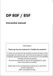
Bench Temperature Control
The bench temperature controller is a self-contained circuit within the ancillary crate 4.
This controller operates from line AC power and without computer control; it is
completely autonomous. A CN77 Process Controller operates as an analog controller
using a P-I-D algorithm and is preprogrammed to control the bench with a variation of
less than 1K. See Sec 7.3 for details on the operation and programming of the CN77.
Two 1N914 diodes (TD28 and TD37) are located on the bench (see Drawing 89-NOAO4201-0814 for their location) for sensing its temperature. Both are wired to the Bench
Temp Controller but only one is selected for use as the monitor. The other can be
selected by opening crate 4, finding the toggle switch on the Bench Temp Controller PCB
(ref Dwg 89-NOAO-4201-4410), and changing its position.
The analog output of the CN77 has a range of 0V to 10V. The output goes to 4 parallel
Apex PA26 power op-amps set for a gain of 2.8X. Each output applies 0V to 28-26VDC
to one of 4 circuits of 50W power resistors mounted on the cryohead thermal distribution
bars, with 2 resistors per circuit for each cryohead. The equivalent resistance of each
circuit is 15 Ohms, so each circuit dissipates up to 50 Watts at each cryohead. The total
possible power dissipation for temperature control is just under 200 Watts.
The CN77 process controller has two
LED displays: the upper display (red
LED) is the Process Value (PV),
which is the bench temperature and is
displayed in Kelvins; the lower
display (green LED) is the Setpoint
Value (SV) and is the desired
temperature in Kelvins. A front-panel
yellow light is ON if heating is
enabled and AC power is at the 28V
power supply. Another front-panel
red light is ON if the sensed
temperature exceeds the programmed
limits for an alarm. Typically the
alarm values are temperatures greater
than 80K and less than 30K
Two banana jack testpoints
have been added to the crate 4 front
panel. They connect to a 0.1 Ohm 25W resistor in series with the +28VDC going to the
power op-amps. This provides a monitor of the current applied to heating the bench.
Series 10kΩ resistors on each banana jack protect the +28VDC from accidental shorting.
An Excel spreadsheet for recording all the programming values of the CN77 is provided
as Bench_CN77setup.xls.
GNIRS Service & Calibration Manual
109
Section 6
CN77 Process (Bench Temp) Controller Setup
DIP Switch Settings: Process 1Vmax := 1,5 ON or 10Vmax := 3,5 ON
Control Description:
Manual Pg
22
22
27
Operation
Set Point 1
Set Point 2
Output Redirection
Input Type
29
Read Configuration
30
31
Filter Constant
Input Scale, Offset
33
Alarm 1
34
35
36
38
42
at power-on
Alarm 1 Low value
and Hi value
Alarm 2
Loop Break Alarm
Output 1
43
44
45
46
47
49
52
53
54
55
56
58
62
65
Current Output
Action Type
Auto-tune PID
Adaptive Control
Anti-Integral
P: Proportional Band
I: Reset Setup
D: Rate Setup
Damping Factor
Output 2
Action Type
Auto-tune PID
P: Proportional Band
Cycle Time
Deadband
Ramp and Soak
Ramp
Soak
Analog Output Option
Communication Option
Remote Setpoint Option
82
* push ENTER twice for Standby (Disable)
once more for
Run (Enable)
* press MENU to access the top-level menu items,
use ENTER to select and enter sub-menu's
Menu Display
SP1
SP2
S1.o.1
InPt
PrOC
dEC.Pt
tEMP Unit
FLtr CnSt
SC.OF
ln 1
rd 1
ln 2
rd 2
ALAr 1
EnbL / dSbL
AbSo / _dEv
LtcH / UnLt
n.o. / n.c.
Abov / bLov / Hi.Lo / bAnd
EnbL / dSbL
AL 1.L
AL 1.H
ALAr 2
EnbL / dSbL
SELF
o°LO
o°HI
4-20 / cUrr
drct / rvrS
EnbL / dSbL
EnbL / dSbL
EnbL / dSbL
ProP bAnd
rESt StuP
rAtE StuP
dPnG Fctr
On.OF / PId
drct / rvrS
EnbL / dSbL
ProP bAnd
CYCL tinE
dEAd bAnd
rAMP SoAc
EnbL / dSbL
EnbL / dSbL
rAMP
SoAc
AnLG OUt
COM OPtn
r.SEt Pont
GNIRS Service & Calibration Manual
Setting
Default / Remarks
page 22 if ID Number Disabled - default
S1.o.1
PrOC
0 - 1.0
FFF.F
°C
S1.o.2 will swap SetPoints 1,2 with Outputs 2,1
set voltage range to agree w/ DIP switches
decimal point
really scaled to be °K
default = 0004; for PID select 0001, 0002, or 0004
min input value (mV) * the natural gain
gives this reading (counts)
max input value (mV) * the natural gain
gives this reading (counts)
contact closure
trigger condition
not_InSt
dSbL
dSbL
default is 00%
default is 99%
dSbL
rvrS
dSbL
dSbL
dSbL
direct = cooling, reverse = heating
controller does PID calc's if enabled
only if non-AUTO PID!
set to 0000 seconds to disable
set to 000.0 seconds to disable
default = 0004, speed of response (lower = faster)
On.OF
rvrS
dSbL
if EnbL, then Output 1 parameters are used
only if Control Type is ON/OFF
dSbL
enter time in HH.MM (zero to 99.59)
not_InSt
PArA
9600
nO
8-bit
1-bit
nO
nO
yES
232C
cnd
SPCE
Frnt
nO
yES
nO
nO
nO
nO
not_InSt
110
huh ?
Section 6
6.5.5 Warmup Controller
The warmup controller is attached to GNIRS at a dedicated hermetic connector, J719, on
the dewar. The Controller uses a preprogrammed P-I-D algorithm and a RAMPed output
function to increase the temperature linearly in 24 hours to 300K. The CN77 has an
OFF-ON output that controls simultaneously 6 power solid-state relays (SSRs). Each
SSR applies 110VAC to one of 6 circuits of 50W power resistors mounted on the bench,
with 8 resistors per circuit. The equivalent resistance of each circuit is 70 Ohms, so each
circuit dissipates 170 Watts on the bench when energized. The total power dissipation is
just over 1000 Watts. Each circuit is individually fused with a resettable circuit breaker
on the rear of the box.
Two 1N914 diodes (TD11 and TD26) are located on the bench (see Drawing 89-NOAO4201-0814 for their location) for sensing its temperature. Both are wired to the Bench
Temp Controller but only one is used as the monitor. The other can be selected by
opening the box, finding the toggle switch on the Bench Warmup Controller PCB (ref
Dwg 89-NOAO-4201-8100), and changing its position.
The CN77 process controller has two LED displays: the upper display (red LED) is the
Process Value (PV), which is the bench temperature and is displayed in Kelvins; the
lower display (green LED) is the Setpoint Value (SV) and is the desired temperature in
Kelvins. Six front-panel white lights are ON if heating is enabled and AC power is being
applied to the power resistors. Another front-panel red light is ON if the sensed
temperature exceeds the programmed limits for an alarm. Typically the alarm values are
temperatures less than 50K and greater than 320K. Two front-panel toggle switches
allow the selection of 3 other SV values, which are preprogrammed within the CN77.
This feature is called the remote setpoint; both switches down selects the default SV as
programmed first with the CN77 menu buttons.
1) Attach cable W719 from the rear of the warmup controller to J719 on the dewar.
Attach the box power cord to MAINS power.
2) Turn on the AC power switch to start operation.
Verify the SV (green LED display) is set to 300.0
3) The controller will immediately apply warming power to the warmup power resistors
with a duty cycle appropriate to a linear increase in temperature.
Monitoring the PV (red LED display) temperature during the 24h period is
recommended.
When the RAMP feature is enabled, the left-most digit of the SV will be flashing. The
RAMP feature works by storing the end-point SV, in this case 300.0, but during the 24
hour ramp time changes the SV from the beginning temperature to the final temperature
on a regular cadence. At turn-on the SV will immediately change to 78K (if the starting
point is 77K) and will increment by 1 every: 24*60/(300-77) = 6 ½ minutes, more or
less. When within 2 degrees of the final SV, the process controller switches to ‘normal’
PID control at the final SV, 300.0 K (80° F) typically for GNIRS.
GNIRS Service & Calibration Manual
111
Section 6
The front-panel of the Warmup Controller box provides additional monitor points. The
two yellow/black pairs of banana jacks are the direct outputs of the temp-sensing diodes,
with LM324 buffering and without conditioning to engineering units, e.g. Kelvins. The
triple banana jacks, red/black/orange, are a source of ±15VDC (limited to 200mA) from
the internal AC/DC power supply.
An Excel spreadsheet for recording all the programming values of the CN77 is provided
as Warmup_CN77setup.xls. Programming the CN77 is further described in Sec. 7.3.
GNIRS Service & Calibration Manual
112
Section 6
CN77 Process (Warmup) Controller Setup
DIP Switch Settings: Process 1Vmax := 1,5 ON or 10Vmax := 3,5 ON
Control Description:
Manual Pg
22
22
27
Operation
Set Point 1
Set Point 2
Output Redirection
Input Type
29
Read Configuration
30
31
Filter Constant
Input Scale, Offset
33
Alarm 1
34
35
36
38
42
at power-on
Alarm 1 Low value
and Hi value
Alarm 2
Loop Break Alarm
Output 1
43
44
47
48
49
52
53
56
58
62
65
82
Control Type
Action Type
Deadband
P: Proportional Band
I: Reset Setup
D: Rate Setup
Cycle Time
Damping Factor
Output 2
Action Type
Deadband
Ramp and Soak
Ramp
Soak
Analog Output Option
Communication Option
Remote Setpoint Option
Menu Display
SP1
SP2
S1.o.1
InPt
PrOC
dEC.Pt
tEMP Unit
FLtr CnSt
SC.OF
ln 1
rd 1
ln 2
rd 2
ALAr 1
EnbL / dSbL
AbSo / _dEv
LtcH / UnLt
n.o. / n.c.
Abov / bLov / Hi.Lo / bAnd
EnbL / dSbL
AL 1.L
AL 1.H
ALAr 2
EnbL / dSbL
SELF
o°LO
o°HI
On.OF / PId
drct / rvrS
dEAd bAnd
ProP bAnd
rESt StuP
rAtE StuP
CYCL tinE
dPnG Fctr
On.OF / PId
drct / rvrS
dEAd bAnd
rAMP SoAc
EnbL / dSbL
EnbL / dSbL
rAMP
SoAc
AnLG OUt
COM OPtn
r.SEt Pont
r.SP.1
r.SP.2
r.SP.3
Setting
Default / Remarks
page 22 if ID Number Disabled - default
S1.o.1
PrOC
0 - 1.0
FFF.F
°C
S1.o.2 will swap SetPoints 1,2 with Outputs 2,1
set voltage range to agree w/ DIP switches
decimal point
really scaled to be °K
default = 0004; for PID select 0001, 0002, or 0004
min input value (mV) * the natural gain
gives this reading (counts)
max input value (mV) * the natural gain
gives this reading (counts)
contact closure
trigger condition
not_InSt
dSbL
dSbL
On.OF
rvrS
default is 00%
default is 99%
(Relay, SSR, or Pulse Option )
direct = cooling, reverse = heating
only if Control Type is ON/OFF
only if non-AUTO PID!
set to 0000 seconds to disable
set to 000.0 seconds to disable
1 to 199 seconds, On/Off time of each cycle
default = 0004, speed of response (lower = faster)
On.OF
drct
only if Control Type is ON/OFF
enter time in HH.MM (zero to 99.59)
not_InSt
not_InSt
* push ENTER twice for Standby/Disable
once more for
Run/Enable
* press MENU to access the top-level menu items,
use ENTER to select sub-menu items
GNIRS Service & Calibration Manual
113
Section 6
6.6. System Failures
This section outlines steps required to respond to plausible system-level failures. They
comprise:
•
•
•
•
•
Power failures
Coolant failure
Network failures
Cryocooler system failures
Bad weather
6.6.1 Power Failures
Power failures can be failures of mains or UPS power only.
Mains power only. In responding to mains power failures, it is important to understand
that there are three critical sub-systems within GNIRS that are powered off mains. These
are the cryocooler heads, the thermal enclosure fans, and the ethernet switch. One should
also recognize that in most cases, mains power failure will also stop coolant flow to the
thermal enclosures and high-pressure helium flow from the compressors to the
cryocoolers.
If the main power interruption is brief - less than a few minutes - there is no need to do
anything specific immediately. Data being taken will probably be lost, however. Once
mains power is restored, it will probably be necessary to restart the EPICS displays and
telnet windows (using nirsStart) to re-establish communications. If, however, the
power failure is more than a few minutes long, the electronics enclosures will start to
overheat and should be powered off (UPS switches off on both). The first symptom of
overheating is a bad ADC health indicator in the GNAAC control window. Once the UPS
power has been turned off, further response is the same as for both mains and UPS power
failure, below.
Mains and UPS power. If all power is lost, then the correct response is to turn off the
UPS power switches on the thermal enclosures. Once power is completely restored, the
system should be re-initialized using the start-up procedures described in section 4.1. In
addition, if the power is off for more than a couple of minutes, it is important to verify
that all four cryocoolers are functioning correctly (see 6.6.4, below).
UPS power only. If only UPS power is lost, turn off UPS power on the thermal
enclosures, and turn the switches on again when UPS power is restored and all external
computer systems are running again. At this point, the procedures are the same as the
start-up procedures in section 4.1. Note that all mechanisms will need to be re-datumed
and the detector temperatures will need to stabilize. This procedure is the same whether
UPS power is off for seconds or many hours.
GNIRS Service & Calibration Manual
114
Section 6
6.6.2 Coolant Failure
If there is a failure of the glycol/water coolant system, the thermal enclosures will
eventually overheat. The likely first symptom of such overheating is a bad ADC health
indicator on the GNAAC control window. If such an indicator appears, make sure that the
problem is indeed overheating and not some other problem before proceeding. If coolant
failure is the problem, shut down the UPS power to the electronics in both enclosures,
and restart according to Section 4.1 once coolant is flowing again. Do not shut off mains
power, in order to keep the cryocoolers running.
6.6.3 Network Failure
There are such a variety of possible network failures that it is difficult to catalog specific
responses for each case. However, the following guidelines should be helpful:
• In general the individual sub-systems are self-contained, so loss of communication
does not necessarily cause them to fail. Wait for the network problem to be fixed, and
attempt to re-establish communication with the instrument computers (use
nirsStart to re-start EPICS and the telnet windows).
• If you cannot communicate with any computer, the problem may be in the ethernet
switch or its connections.
• If you can communicate with some computers, but not others, try re-booting. If that
does not work, try turning UPS power on and off. Note that either course of action
will require re-initializing the system in question, including datuming mechanisms
and stabilizing detector temperature (where appropriate). Loss of communication
between the GNAAC co-adder and the DHS can require re-booting both systems.
Note that the co-adder does not control the detector directly, so temperature control is
maintained.
6.6.4 Cryocooler Failures
There are several possible failure modes of the cryocooler system.
Compressor failure. If the compressors fail (stop), the supply pressure will drop quickly
and the cryocooler heads will shut off automatically. If the heads are off for more than a
couple of minutes, there is a risk that one (or more) will freeze up if the instrument is
cold. If this occurs, when the heads are started again, the outlet gas line will be colder
than the inlet line on that head. Under normal operation, the outlet gas lines are always
warmer than the input gas lines.
"Frozen" coldhead. If a coldhead is frozen, which can occur if it is stopped for too long
when the instrument is cold, the following procedures will probably fix the problem:
• A quick fix is to turn off all the other heads, and try running the problem head by
itself (running maximum gas flow through the head). If the outlet line continues cold
after a minute or so, try the next step.
GNIRS Service & Calibration Manual
115
Section 6
• Turn the problem head off, but at a point in its cycle where gas is flowing through it.
You should turn off the other heads so you can hear better, and then "jog" the head by
connecting power briefly. Do this until you hear gas flowing through the head. At this
point, you can turn on the heads on the opposite side of the instrument to maintain as
much cooling as possible. Wait about 5 minutes, then try starting the head. If the
outlet gas is still cold, you may want to try again (wait a little longer).
• If you are unable to get the problem head to run correctly, it is marginally possible to
run the instrument with 3 heads. Turn off the problem head (make sure that gas is not
flowing through it, now) and turn the other 3 heads on.
In general, a coldhead will not "freeze up" spontaneously - it will do so only if it has been
stopped for a while. The solutions outlined above may also help restart a contaminated
coldhead, but unless the contamination is purged, the problem may reappear.
Low compressor pressure. If the compressors are providing insufficient gas flow, the
cryocoolers will not be able to maintain proper instrument temperature. This will affect
the science detector and the bench temperature. The first obvious symptom will probably
be a loss of detector temperature control (error condition on GNAAC temperature
monitor), although the bench may start deviating from nominal before that.
If this occurs, the helium lines need to be topped off.
6.6.5 Really Bad Weather
For most bad weather, the instrument can be left in the normal "end-of-night" state,
which consists of having the window cover closed and the detector deactivated. This
assumes that people will have some direct access to the instrument.
If the summit is evacuated, the main concern is having the instrument warm up
unnecessarily. Probably the best way to ensure that this does not happen is to leave the
cryocooler control switches in manual mode, and "on". If the compressors are not
operating, the cryocoolers are safeguarded by the differential pressure switch, but if the
compressors are operating (or start up), the crycoolers will start up as well. Note that
there is some risk that one of the heads will "freeze up" (see 6.6.4 above), but there is
little one can do to prevent that and cooling will still be better than with all heads off.
(Note, too, that if the power is off for an extended period, odds are the heads will warm
up enough so that freezing is not an issue).
UPS power to the array controller should be turned off (deactivate first, of course).
If the instrument warms up significantly, so that the bench is still above ~85K when
people return to the mountain, cooling will be faster if the pre-cool system is used. Also,
if the instrument has warmed up at all, even if not above 85K, check the helium pressure
in the pre-cool system since it will have lost gas due to thermal expansion. See section
5.2 for more details on these procedures.
GNIRS Service & Calibration Manual
116
Section 6