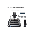
1
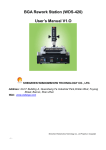
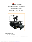
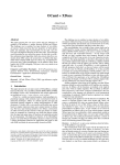
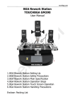
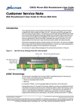
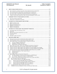
BGA Rework Station ZM-R380B
Manual
Preface
Dear customer, Thank you for using the BGA rework station ZM-R380B of Shenzhen
Zhuo Mao Technology Co., Ltd.
Features of ZM-R380B:
1. Choose imported high-precision materials (temperature sensor, PLC, heater) to
control the BGA desoldering & soldering procedures precisely.
2. The Top(hot-air) & bottom(IR) heaters heat independently, and it can set up 8 rising
temperature segments and 8 constant temperature segments to control. It can save 10
groups of temperature curves at the same time.
3. This machine can be connected to a computer to be controlled more conveniently with
a built-in PC serial port and proprietary software attached to it.
4. Choose imported high-precision thermocouple to detect top/bottom temperature
precisely.
5. Top & bottom heating can be controlled independently by the temperature graphs. A
cross-flow fan cools rapidly to protect the PCB from deformation when welding.
6. After finishing desoldering & soldering, there is an alarming. The machine is equipped
with a vacuum suction pen to facilitate the removing of BGA after desoldering.
7. Use a V-groove equipped with a flexible fixture for PCB positioning to protect the
PCB.
COMPANY PROFILE
Shenzhen ZhuoMao Technology Co., Ltd. is a high-tech enterprise involved in research,
development, production and marketing. Since its establishment, with strong technical
force, faithful business philosophy, a sound sales network, comprehensive and
thoughtful after-sales service, through the absorption and the introduction of foreign
advanced technology, we improved ourselves and won customers trust & supports in the
filed of BGA rework systems and peripheral auxiliary equipment.
Company's product are sold in most cities in China and exported to Japan, South Korea,
North Africa, Vietnam, Southeast Asia, the Middle East, Europe and the United States
etc. We got a strong vitality and higher visibility in the same industry. Our company will
continue adhering to the idea of "profession, innovation and integrity", to provide our
-1-
customers with more efficient high-quality and convenient services! Your smile is always
Zhuomao’s constant pursuit.
In order to give full play to the product's superior performance and to ensure the safety
of users, please carefully read this manual before use. This manual is accessory with the
machine; you should keep after use for future repair and maintenance of the rework
station.
Any doubt of this equipment and special requirements, please contact us at any time.
Content
Item
1
st
、Installation
03-03
2
nd
、Specifications
03-03
3
rd
、Main Structure
04-04
4
th
、Operation
05-13
5
th
、Reballing processes
14-14
6
th
、Repair and maintenance
15-15
7
th
、Precautions
16-16
Appendix: the temperature curve of welding
-2-
page
17-18
1
st
、Installation
1. Be away from flammable, explosive, corrosive gas or liquid.
2. Avoid damp places, the air humidity is less than 90%.
3. Temperature -10 ℃ ~ 40 ℃ , avoid direct sunlight, prolonged sun exposure.
4. No dust, fibers and metal particles floating in the operational environment.
5. The installation place required flat, solid, no vibration.
6. Place heavy objects on the body are strictly prohibited.
7. Avoid air-conditioners, heaters or fans direct airflow.
8. The back space of rework station should be reserved 30CM for heat dissipation.
9. The placing table (900 × 900 mm) be flat, the relative level of a height 750 ~ 850 mm.
10. Distribute wiring must be handled by a qualified professional technician, the main
line is 2.5 square feet. Equipment must be well grounded.
11. Switch off the power after use, Power must be disabled if a long-term no need.
2
nd
、Specifications
1. Power: AC220V ± 10% 50/60Hz
2、 Total power: 3.25KW
3. Heater power: The upper heater 0.8KW; The bottom IR heater 2.4KW; Other Power:
0.05KW
4. Temperature control: K-type thermocouple of high closed-loop control:
Upper and lower parts independently measured;
Temperature precision is within ±3 degree.
5. Positioning mode: V-groove PCB positioning.
6. PCB size: Max 300*310mm
Min 42*42mm
7. Dimension: 445×430×600mm
8. Weight: 25kg
10. Exterior color: black
-3-
3
rd
、the main structure description
( 1) structure description
s
i
x
a
Y
1
0
e
l
d
n
a
h
t
s
u
j
d
a
s
i
x
a
Z
2
0
e
l
d
n
a
h
t
s
u
j
d
a
m
e
t
s
y
s
g
n
i
l
o
o
c
1
1
p
u
o
r
g
g
n
i
t
a
e
h
3
0
r
e
t
r
o
p
p
u
s
d
r
a
o
b
B
C
P
2
1
e
l
z
z
o
n
4
0
t
r
a
t
s
6
1
x
o
b
g
rn
ei
tt
aa
ee
hh
mm
oo
t
tt
t
oo
bb
78
00
t
s
u
j
d
a
r
i
a
t
o
h
p
o
t
5
1
t
n
i
l
p
s
B
C
P
6
0
r
e
l
l
o
r
t
n
o
c
.
p
m
e
t
m
o
t
t
o
b
4
1
r
e
t
s
e
t
m
o
t
t
o
b
5
0
C
L
P
3
1
e
t
a
l
p
e
m
a
n
9
0
p
o
t
s
7
1
h
c
t
i
w
s
0
1
o
t
u
a
/
l
a
u
n
a
m
g
n
i
l
o
o
c
8
1
( 2) function introduction
NO.
NAME
FUNCTION
USE METHOD
1
Y-axis adjust handle
Adjust the top heater right and left
2
Z-axis adjust handle
Adjust the top heater up and down
3
Heating group
Heating the BGA from top
4
nozzle
Focus on the BGA surface
5
Lower thermometer
Feedback the true information
6
PCB splint
Support the PCB board
7
Lower heating plate
Heating the BGA from bottom
8
Lower heat box
Assembly, protect the heating plate
9
nameplate
Information identifying the machine
10
Power switch
Control power on and off
11
Cooling system
Cool the PCB board after heating
Auto activated after heating
12
PCB supporter
Stop the PCB board from distorting
Adjust the height of the screw
13
PLC
Control the top temperature
According to the manual
14
Lower Thermostat
Control the lower temperature
According to the manual
15
Top hot-air adjust
Adjust the top air flow
Turn left and right to adjust
16
start
To start the machine
Press 5 seconds to start it
17
stop
Stop the machine during working
Press 5 seconds to stop it
18
Cooling manual/Auto
Switch cooling manual and automatic
-4-
Adjust by Z-axis handle
4
th
、 Program
setting and operating instructions
(1) Program setting:
Meter setting:
Top/bottom PLC are using same meter, some using.
PLC appearance:
PV410
10 11
PV
8
9
TIME COM
SV
SV
AL1
SET
PROG
RUN
PROG
PTN
PTN
PRO
STEP
OUT1 OUT2
AUTO
HAND
PAR
SET
PV410
BIP
6
PLC panel instruction
-5-
MAN
AT
PUN
7
MV
DISP
SELE
5
4
3
2
1
Setting process:
First turn on the power supply
1) Choose temperature profile: (set groups) press PTN button (can
save 10 groups temperature profiles), Press PTN groups will be
changed (1, 2, 3, 4, 5, and 0) choose one of them for temperature
st
profiles (We take 1
group for example)
PV
DISP
TIME
SV
COM
SET
PROG
1
MV
MAN
SV
AL1
RUN
PIN
PRO
STEP
OUT1
RUN
AUTO
HAND
PIN
PAR
SET
OUT2
Bip
PV410
2) Preheating: Slope(r)
Press SET button enter into temperature curve,r1 stands for
slope (the temperature will rise at the speed of 3℃ in one second)
3.00 stands for 3℃/second, press number increase button to
adjust. Press PAR button enter next step.
PV
r1
SV
DISP
TIME
SET
3.00
1
PIN
PROG
RUN
PRO
STEP
MV
MAN
SV
AL1
OUT1
RUN
AUTO
HAND
PIN
PAR
SET
OUT2
Bip
PV410
3) Preheating:
COM
Temperature (L),
Press number increase button to adjust,160 stands for preheating
temperature 160℃. Press PAR button enter to next step.
-6-
PV
L1
SV
DISP
TIME
COM
SET
160.00
1
PROG
RUN
PIN
PRO
MV
MAN
SV
AL1
OUT1
STEP
RUN
AUTO
HAND
PIN
PAR
SET
OUT2
PV410
Bip
4) Preheating:
Time (d),
Press number increase button to adjust, D stands for the time
how long the temperature stays at this stage. Press PAR button
enter to next step.
PV
d1
SV
D IS P
T IM E
COM
MV
M AN
SV
A L1
SET
30
1
PROG
RUN
PIN
PR O
STEP
O UT1
RUN
AUTO
HAND
P IN
PAR
SET
O UT2
PV410
B ip
Remarks: The remaining seven-segment temperature settings are
same as above exactly.
PAR
SET
PV
Hb
SV
D IS P
T IM E
COM
MV
MAN
SV
AL1
SET
300
1
PROG
RUN
P IN
PRO
STEP
O UT1
RUN
AUTO
HAND
P IN
PAR
SET
O UT2
PC410
A LTEC
REX--C10 Temperature controller:
Thermostat
temperature
temperature controller.
-7-
controller
is
adopted
REX-C10
s h o w a c tu a l te m p e r a tu r e
PV
s h o w s e ttin g te m p e r a tu r e
m ove
SV
dow n
set
up
SET
RKC
REX-C10
Setting Method:
1) Hold down the adjustment button for 1-2 seconds, then the setting of the
temperature a bit flash, press numerical increase (decrease) key to change.
And then move button to move the modified adjusted value of 10, and
finally to 100, after finished, press the SET to confirm.
Proposal setting
ALM
:180℃
PV
OUT1
OUT2
SV
AT
SET
RKC
REX-C10
(2): Use of the external computer
The device can connect with an external computer, you can observe two
-8-
temperature curves of the head of internal heating wire and external
measurement of galvanic through the computer interface, and you also can set
the temperature, time and other parameters through the computer, but also
can achieve data transfer between computer and instrument, store many
curves and facilitate to print out. (Note: This feature is limited to the upper
heating control)
Statement: the related temperature parameters of the equipment can be
set-up and stored completely through the instrument age, but in order to set
the temperature more user-friendly, more intuitive, and easy to store, and print
the temperature curve, our company specially developed this software
(1) Software Install
1)Lowest requirement for computer configuration.
a. CPU:P Ⅲ 800
b. Memory:128M
c. Video Card:4M
d. CD ROM
e. Serial Communication Interface
2)Software Installation,
a Put the video into the video card, open CD diver,run“V2.08setup” appear language
select.
Choose” English” and Click “Next” to enter Picture 1
Picture 1
b Click“Next”to enter Picture 2
c After enter “Picture 2”,click“Next” button,enter Picture 3
d Click“Next”,enter Picture 4
-9-
Picture 2
Picture 4
Picture 3
Picture 5
e Click“Next”,enter Picture 5
f Click“Install”
,enter Picture 6,start installing.
Picture 6
g Click“Finish”
,finish installing process.
- 10 -
Picture 7
(2) Using of software
1)Connect the computer series port and machine communication port with the
enclosed date cable.
2)Open power of the equipment.
3)Click
Zhuomao reworker.lnk
on the desktop,enter into temperature curve
recorder system interface(picture 8)
4)Set the temperature, time, slope parameter for very segment.
a Click“Profiles setting”,the interface will enter into (Picture 9),according to
“welding BGA” and solder ball to set the parameter for each segment. And for
specific date and operating parameters, please see the construction book for
reference.
b Note 1:This software is for showing the temperature curve and recorder, the
software does not have the motion control functions, for the movement of the
machine need manual adjustment.
c Note 2:The related temperature profiles, you can set through the meter on the
machine. However, in order to facilitate the users for temperature setting, in particular
for the temperature curve showing, save and print, so we develop and expand this
software.
5)Manually operation for the machine, make the equipment enter into heating state,
and for specific operation, please see the construction book for reference.
6)Click “download Controller” ,so the temperature for just setting can be
down load to the programmable controller.
- 11 -
7)Click“Run/Stop”
,the machine will carry out heating motion.
8)At this time you can see the temperature curve.
9)Curve 1(Green)shows:The actual measurement of heater temperature
10)Curve 2(Red)shows:External Sensor temperature (Testing through the
sensor on the machine)
11)During the process of heating,Click“Run/Stop”
,or click “Stop”on the
control panel,heating process will be stop.
12)Click“Exit system”
,computer will exit the application programmer.
(三) Development Features Instruction
1)“Upload from Controller”:Click this button can upload the internal
instrument parameter from controller to the computer; it can set a group of data each
click.(Note: the programmable controller can save 10 groups itself)
2)
“download Controller”: Click this button can download the parameter from
computer to the controller;
3)
“Save”:After using the software for heating,
“Profile View” curve display
page will show the two temperature curve, use this button can save the curves
to any position on the computer hard disk.
4)
“Open”:Through using this button can pick up the temperature curve stored
in computer.
5) “Print”:Through an external printer can easily print the current curve.
- 12 -
Picture 8
Picture 9
Picture 11
Picture 9
Picture 10
Picture 12
2 Computer settings (upper heater)
1)
Click on the icon, the screen display as (Figure 11), bottom of the screen for setting the
temperature curve parameters, drag the cursor point 160, with reference parameter set reference value
in the table of parameters to be modified.
2)After the setting of the paragraphs parameter, click on as (Figure 11) "to download data to the
instrument" so that the data can be stored in the instrument, (Remark: The group number displayed on
the meter number during transmission is the NO. of the data that transmitted, the original number of the
- 13 -
data in the instrument will be overwritten)
(2)
Operation
1. Turn on the Main Power Switch, then check whether there is cold air blow out from the top of the
hot air nozzle, if not, it is strictly prohibited to turn on switch, otherwise it will burn the top heater;
2. Set the procedures as the above method, and install the computer data lines correctly, turn on
the power supply.
3. Install the PCB board which is need to weld and the appropriate nozzle; make the centers of the
nozzle are on the center of the PCB board, turning Y-axis adjustment handle of the heater, so that the
nozzle is at the height of 3-5mm of the top surface of the PCB board.
4.
Presses the “start”, the system will automatically heating and welding; the temperature trend
curve will appear on the screen;
5.
After welding, the system will automatically alarm, and stop heating. And then turn the Y-axis
adjustable handle of the heater upward, check the welding results. Welding process is completed.
5th Reballing Process
a. Fix the BGA chip on the base of our universal reballing station, adjust two sliders (without springs) to
fix the chip.
b. Select the appropriate steel mesh according to chip type. Fix the steel
mesh to the ceiling cover and tighten it with 4 M3 screws, covered with lid. Adjust 4 Jimmy on the base to
meet the suitable height required.
c. Observe the hole on steel mesh which should be completely coincide with
the solder holes on BGA. If not coincide, we must remove the cap to
reposition to ensure steel mesh holes aligned with the chip.
- 14 -
d. Locking two no spring fixed slide, remove the BGA chip and coated with a thin layer of solder flux, card
the chip into the base again, covered with lid
e. Put into solder ball, clench hands and gently swaying reballing station to
ensure the solder ball completely filled in the holes and pour out extra solder
balls.
f. place the reballing station on the flat location, remove the lid, carefully scored
BGA chips. Observe the chip, if individual solder balls are not in the hole rightly,
please correct it with forceps.
g. It’s convenient to use our different types of repair stations or welding machine
to fix solder ball. Heat solders balls on the BGA to soldering it on BGA, thus
reballing finished.
6 th 、repair and maintenance of the machine
(1) Replacement of top heating wire (as pictured)
fa n
t o p f ix e r
p la s t i c c o n n e c t o r
h e a t i n g w ir e f i x e r
h e a t i n g w ir e
h ig h - t e m p e r a t u r e in s u l a t i n g p a p e r
cover
- 15 -
d
a
e
h
r
e
p
p
u
m
u
n
i
m
u
l
A
t o p n o z z le
1、 First power off, make the top heater completely cool;
2、 The replacement of fan:
Take off the cover, and then you can replace the fan.
3、 And then take them off as following order: cover, fan, top fixer, Plastic connector, and heating wire
fixer. (As pictured)
Remark: when you change the heating wire, it must be wrapped by High-temperature insulating paper.
(2)
Replacement of heating plate:
heating pad
lock screw
fixed plate
heating panel card
heating box
1、(as pictured)remove the tank cover。
2、remove the heating pad,take out heating panel card from the back,replace the heating plate。
3、demolition the power line as required,and install the new board,weld the power cord。
(3) Maintenance of the machine
Clean the surface of heat plate, after power off and cool the heating plate, use fine cotton and oil
or alcohol wipe it lightly.
!
7 th 、 Precautions
1. ZM-R6820G Rework Station use AC220V power, working temperature may up to 400 ℃, Improper
operation may cause damage to the equipment and even endanger the safety of the operator. Therefore
must strictly abide the following:
a. No directly fan or other blowing air to the station when working, otherwise may result heater
thermometric distortion and equipment or components damage;
b. prohibited flammable gases or liquid around the machine; After booting, forbidden combustibles touch
high temperature district and peripheral metal parts, otherwise easily cause fire or explosion;
c. To avoid high temperature scald, forbidden touching high temperature fever zone. PCB board still
warm when completed, operation process should take necessary protective measures;
d. PCB board should be placed on V type support shelves and used slider pairs to support PCB board in
the centre;
e. Metal or angular and sharp objects are avoided on touch screen surface;
- 16 -
f. upper and lower heater inlet must not be blocked, otherwise heating wire will be damaged;
g. After work, please guarantee natural cooling for 5 minutes, then close Power Switch;
h. When in work, metal objects or liquid fall into rework station, immediately cut power, unplug power
plug, until it cooled, then eradicate litter, dirt; it will be influenced if grease on the heating panels and
accompanied by odor when rebooting. Please keep the machine clean and timely maintenance.
i. when appears abnormal warming or smoke on the machine, immediately disconnect power and notify
technical service personnel to repair it; Remove the connections data line between computer and
devices, hold the plug to unplug the data line, to avoid damaging internal connection.
2. belongs following one and thereby behavior triggered other damage not Company guarantee scope!
a. Failing uses the method in manual to operate in wrong conditions or environmental operation;
b. The Company product outside reasons;
c. Not this company’s transformation and maintenance;
d. not accordance to the method stipulated when using the products
e. unpredictable situation that the company scientific technical level not reached
- 17 -
Normal BGA welding and disordering parameters
( for reference)
The temperature curve of lead welding
41*41
the temperature setting of the BGA welding:
preheating insulation
heating
welding1
welding2
cooling
upper
160
185
210
235
240
225
time
30
30
35
40
20
15
bottom
160
185
210
235
240
225
time
30
30
35
40
20
15
slope
4.0
3.0
3.0
3.0
3.0
3.0
IR
180
38*38
the temperature setting of the BGA welding:
preheating insulation
heating
welding1
welding2
cooling
upper
160
185
210
225
235
215
time
30
30
35
40
20
15
bottom
160
185
210
225
235
215
time
30
30
35
40
20
15
slope
4.0
3.0
3.0
3.0
3.0
3.0
IR
185
31*31
the temperature setting of the BGA welding:
preheating insulation
heating
welding1
welding2
cooling
upper
160
180
200
215
225
215
time
30
30
35
40
20
15
bottom
160
180
200
215
225
215
time
30
30
35
40
20
15
slope
4.0
3.0
3.0
3.0
3.0
3.0
IR
180
The upper is the reference temperature of the lead BGA
- 18 -
The temperature curve of Lead-free welding
41*41
the temperature setting of the BGA welding:
preheating insulation
heating
welding1
welding2
cooling
upper
165
190
225
245
255
240
time
30
30
35
55
25
15
bottom
165
190
225
245
255
240
time
30
30
35
55
25
15
slope
4.0
3.0
3.0
3.0
3.0
3.0
IR
210
38*38 the temperature setting of the BGA welding:
preheating insulation
heating
welding1
welding2
cooling
upper
165
190
225
245
250
235
time
30
30
35
45
25
15
bottom
165
190
225
245
250
235
time
30
30
35
45
25
15
slope
4.0
3.0
3.0
3.0
3.0
3.0
IR
210
31*31
the temperature setting of the BGA welding:
preheating insulation
heating
welding1
welding2
cooling
upper
165
190
220
240
245
235
time
30
30
35
40
20
15
bottom
165
190
220
240
245
235
time
30
30
35
40
20
15
slope
4.0
3.0
3.0
3.0
3.0
3.0
IR
210
The upper is the reference temperature of the lead-free BGA
Such as set 0 when the demolition of the cooling section of BGA.
- 19 -