1
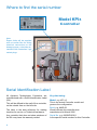
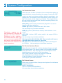
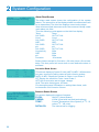
AQUARIUS
TECHNOLOGIES PT Y LTD
WATER QUALITY CONTROL
KPI Intelligent
Cooling Water
Treatment Controller
USER MANUAL
Dec 2008 Version 11.0
Contents
Congratulations
Where to find the serial number
Section contents
Installation guidelines - Section 1
System configuration - Section 2
Manufacturer’s Warranty - Section 3
Unit 1, 23
Richland Avenue
Coopers Plains QLD 4108
PO Box 71
Coopers Plains QLD 4108 AUSTRALIA
3
4
5
6
10
38
t: +617 3274 4750
f: +617 3274 4736
w: www.aquariustech.com.au
This document is subjected to Aquarius Technologies Pty Ltd trading terms and conditions
which can be obtained from the following link http://www.aquariustech.com.au/terms.html
KPI 3 Intelligent Water Treatment Controller
Congratulations
We know you will be happy with your decision
to purchase a new KPI 3 Intelligent Cooling
Water Treatment Controller.
These units
are now supplied with standard features that
are considered optional extras in most other
systems, if available at all.
Let us help you learn about your new
Controller. This manual will take you through
all of the functions available from the keyboard
to the display, and provides a clear and logical
sequence for processing the configuration
settings.
The updated software now incorporates our
newly released Aquarius Proprietary Logic (APL),
which has capabilities to control monitoring and
responses to much tighter tolerances that were
ever possible in earlier models.
Please also take the time to send us details
of the Installation on the Registration Form
provided. This will enable us to provide the very
best level of technical support should you need
to contact us for any reason.
You also have the comfort of knowing that
these models are capable of being upgraded
by connecting to a notebook computer, locally
or via the optional cellular communications
package. They are also scalable in terms of
adding modules to expand capacity over time.
Models covered by this Manual
• KPI 3 Intelligent Cooling Water Treatment Controller
3
Where to find the serial number
Model KPI3
Controller
Note
Export Units will be supplied
with a Junction Box for wiring
electrical connections to the
dosage pumps, solenoids etc.
instead of the Australian 3 pin
socket plugs
Serial Identification Label
All Aquarius Technologies Controllers are
manufactured with a Serial Identification Label
(SIL).
This will be affixed to the wall of the controller,
on the outside face on the left side.
The label is the best reference for making
inquiries for service or Technical Assistance.
Any controller that does not show evidence of
the SIL may have the warranty voided.
4
Key data being:
Model: e.g. KPI v3
This is the actual Controller model and
governs the configuration.
Build: e.g. MAR-06
Would indicate this controller was
manufactured in March 2006
Serial No: e.g. 0603KPI30011
Is the specific serial number for this Controller
Section Contents
1
Installation Guidelines
Minimum System Requirements
Maintenance of Sensors
•Cleaning Flow/Cond/Temp sensor
•Cleaning pH/ORP sensor 6
6
7
7
•Accessories & Spare Parts - Reagents
•Sensors
•Test Meters
•Routine Testing
•Regular Inspections & Maintenance
•Warnings
7
7
7
8
8
2
System Configuration
Aquarius KPI 3 Control Systems
10
Screen
10
Buttons
10
•Default Screen 11
•Calibration
– Access from the CAL button 11
•Units Select in Calibration Mode
11
•Combination Calibration Mode 11
•Erase WUM Totals Mode
11
•pH Calibration Mode
11
•ORP Verification Mode
12
•Cond/Temp Mode
12
•Steps
in Temperature Calibration 12
•Steps
in Conductivity Calibration 12
•Corrosion Cal
13
•Erase Calibration Mode
14
•Panel Selection Mode
14
•Factory Alert Screen
14
•Source Data Screen
14
Set Mode 15
•Set Screens Menu
15
•Set Time & Date Screen
16
•Set Data Logger Screen
16
• Set Alarms Screen
16
•Set
Alarm Screen - Name & Phone
17
•Set Flow/Velocity Screen
17
•Set Corrosion Screen
17
•Set Probe Factors for Various Metals 18
2
System Configuration
•Set Conductivity Screen
•Set ORP Screen
•Set pH Screen
•Set Inhibitor Screen
•Set Water Usage Meter (WUM) Scr
•Set Dispersant Screen
•Set Secondary Bio Screen
•Set Pre-Bleed/Bleed Lockout Screen
•Set 7-day Timer Screen
•Set Disinfection Screen
•Set Calcium Hardness Screen
•Set Protocol Screen
Read Mode
19
19
20
21
21
22
22
23
23
24
24
24
25
•Alarm Read Screen
•Corrosion Read Screen
•Sensors Status Screen
•Conductivity Read Screen
•ORP Read Screen
•pH Read Screen
•Inhibitor Read Screen
•Water Usage Meter (WUM) Read Scr
•Dispersant Read Screen
•Secondary
Bio Read Screen •Pre-Bleed/Lockout
Read Screen •7-Day Timer Read Screen
•Disinfection Read Screen •LSI/FAH Read Screen •Protocol Read Screen Tank Alarm (with wiring instructions)
Data Logging & Communications Setup
•Hyper Terminal Set Up
•GSM modem set up
•Adding a SIM card to GSM modem
•Adding phones nos for Alarms
•Using AquaGuard 2 software
•Adding AquaGuard 2 Activation Key
•BMS 4 - 20 mA Interface
26
26
26
27
27
27
28
28
29
29
30
30
30
31
31
31
32
32
33
33
33
34
34
35
3
Warranty & Registration
Manufacturer’s product warranty
38
Commissioning & Warranty Registration
39
5
1 Installation Guidelines
Important
If the supply cord is damaged, it shall be
replaced by the manufacturer or its service
agents or similarly qualified person in order to
avoid a hazard.
Before you start
Select a suitable location for installation preferably in close proximity to the main system,
protected from the public and environmental
factors such as direct sunlight. A wall area of
approx. 0.75 m. wide by 1.0 m. high is ideal for
mounting your controller. A minimum floor area
of approx. 1.5 m x 0.6 m below the controller is
required for the chemical tanks. This will vary
according to the number and type of chemicals
being used for dosing.
It is important to consider environmental
elements when installing. It is a requirement
to provide protection for accidental spills of
chemicals and that includes any leaks that
can develop from pump pressure lines. Some
chemicals will damage materials used in
construction of buildings, particularly roofing.
Never assume that the equipment will not leak,
under certain conditions that will occur. It is
the responsibility of the installer to ensure that
such events do not create damage that should
have been avoided by correct site selection
and the provision of adequate bunding at the
time of installation.
System requirements
There are several minimum requirements that
should be established BEFORE the controller
is installed;
•Minimum 20 mm (3/4) take-off and line to
supply sample water to the system,
• Minimum 12 litres/minute supply flow to
ensure proper operation of sample readings,
dosage and bleed off rates.
• Adequate bunding is provided for the system
and chemical drums to prevent spills causing
damage.
• Availability of approved connection to
power. A ‘clean’ 220 - 250 vac 50 Hz @
10 amps supply (some options may need
more than one outlet, or increased current
capability).
6
The terminal strips supplied with the controller
activate a 240V AC supply rated @ 7A
combined. These terminals are active when
the Relay Output for the specific function is
activated, eg, pH terminal will go active 240Vac
when the pH monitored value is outside the
set-point. These outputs should be wired by
a qualified electrician. The Neutral and Earth
connections for each output must be connected
to the commoning blocks using the terminals.
To install
Unpack the equipment and check for any
damage. Ensure all parts are accounted for.
Assemble the inlet and outlet PVC valves on
the sensor manifold. Remove the protective cap
and fit the pH/ORP probe into the manifold.
Connect a 20 mm line from the circulating pump
discharge line, or system common discharge
header, to the inlet of the manifold. Connect
a return line from the manifold outlet valve
preferably in PVC pipe to the pump suction or
common suction header or to the tower basin.
Connect a line from the Bleed solenoid to an
approved waste discharge
If installing a BCD Feeder, assemble the BCD
feeder as per its separate instructions and floor
mount in the vicinity of the system. Plumb from
the BCD control solenoid to the inlet of the BCD
feeder and from feeder to the system.
Install chemical tanks as required, and ensure
each dose pump discharge tubing is connected
to the manifold injection points provided.
Run a flow of water through the system under
normal operating pressures. Check for, and
repair any leaks. The Aquarius Controller is
now ready for use.
Liaise with your chemical specialist for advice
regarding any bunding requirements, floor
drainage requirements and fresh water supply
in the vicinity of chemical tanks. In addition
check on local authority regulations for
discharge of trade waste, chemical storage
and hazards control etc.
Installation Guidelines
Maintenance and Care of Sensors
Foulants can lead to inaccurate sensor
readings. Sensors should be cleaned and
calibrated regularly using the following
procedures.
Cleaning of the Clear Bowl Strainer
The strainer should be regularily cleaned of
debris, to ensure adequate flow in the manifold and allow the control valve to maintain
the desired flow velocity across corrosion
sensor
Cleaning of Flow/Conductivity/Temp Sensor
Isolate the flow to the manifold. Remove the
locking nut from the Flow/Conductivity/Temp
sensor. Abrade the sensor surface with
300–400 grade wet–and–dry paper until the
surface is clean, the two carbon electrode
surfaces are clearly visible, and the surface
wets out freely.
Ensure flow paddle is free from debris. Rinse
the sensor in fresh water and replace it in the
manifold.
Cleaning of pH/ORP/GND reference sensor
Isolate flow to the manifold.
Remove the sensors from the manifold by
loosening the lock nut and withdrawing the
sensor from the manifold.
Rinse the sensors in fresh tap water and
remove any visible fouling. This should be
done carefully by lightly scrubbing with a
tooth brush or similar.
Place the sensors in the Electrode Cleaner
solution (AS9500) for about 5 minutes to
completely dissolve any trace of inorganic
foulants.
Remove and rinse thoroughly in fresh water
before replacing it in the manifold.
Proceed to calibration or verification of
sensors as outlined in the commissioning
section.
1
Cleaning of the Corrosion Sensor
Gross debris should be carefully wiped off the
sensor, if the sensor is corroded and pitted
it should be replaced to ensure accuracy of
the corrosion readings.
Accessories and Spare Parts - Reagents
AS1413 -1413 uS/cm conductivity solution
AS7004 - pH 4 buffer solution
AS7007 - pH 7 buffer solution
AS5250 - 250 mV ORP solution
AS5475 - 475 mV ORP solution
AS4250 - pH 4.01/250 mV combo solution
AS7086 - pH 7.01/86 mV combo solution
Sensors
PR_FCT – Combination Conductivity, Flow
and Temperature Sensor
PR_pHORP – Combination pH, ORP and
Ground reference Sensor
PR_CORR1 - Combination ring sensors
for corrosion monitoring on mild steel and
copper specimens
ROTOFLOW_G - Water Wheel type sensor
in the manifold to measure and control flow
and velocity across the corrosion sensor
Test Meters required
HI9813 Portable pH/cond meter
HI8314 Portable pH/ORP meter
Routine Testing
The use of an Aquarius KPI v3 control system
will automatically vary the dosages and
maintain good conductivity, pH, ORP and
disinfection control, even where there are
wide fluctuations in system load or demand.
The principles of “Best Practice” and “Duty of
Care” that are the responsibility of the system
owner, dictate that all systems should be
routinely serviced and tested chemically and
the results logged.
7
1 Installation Guidelines
Warnings
Chemicals in use as part of the treatment
program may be hazardous. Please refer to
the full Material Safety Data Sheets (MSDS)
provided by your chemical supplier and ensure
all personnel involved are aware of the handling
and safety procedures.
Both pH & ORP sensors age with time and
temperature, and have a typical life span of
24-36 months depending on the application
in which they are operating and should be
replaced accordingly.
Please read and understand all safety warnings
on chemical containers before servicing any
dosing equipment.
Where fitted, flow sensors, solenoid valves and
wire strainers should be checked for correct
operation and cleaned of any debris every
month so they work efficiently.
Wear as a minimum - safety goggles and gloves
when servicing the dosing equipment.
Injection non-return valves and pumps should
be cleaned and checked at least annually.
Do not mix concentrated acids and oxidising
agents as explosion, and/or toxic and lethal
gas may be evolved, and/or fire result.
Sodium Hypochlorite being highly alkaline may
lead to scale formation on its dose injector and
this may require acid cleaning on a frequent
basis.
Keep all chemical containers sealed and free
from contamination.
Regular Inspections and Maintenance
For optimum results and continued accuracy,
the complete operation of the controller system
should be verified at least on a monthly service
basis.
All sensors should be inspected, cleaned and
calibrated as necessary every month.
Maintenance
1 Month
Clean and Calibrate FCT Probe
√
Verify Flow ON/OFF
√
Verify pH/ ORP Probe
√
Test Outputs
√
Test Pumps/Solenoid Operation
√
On the peristaltic dose pumps, the squeeze
tubes and roller block should be checked at
least annually and should be replaced every
12-24 months.
More regular maintenance may be required for
the larger 0.56 gal/hr pumps, due to increased
pumping rates.
Chemical suction and discharge tubes
should be inspected monthly and replaced as
necessary
3 Months
Clean and Calibrate pH/ORP Probe
√
Check/Clean Injectors
√
Inspect Suction/Discharge Tubing
√
Check/Clean Solenoids
Peri. Pump - AP Service Kit
Peri. Pump - AP Overhaul Kit
8
6 Months
1 Year
2 Years
√
√
√
Installation Guidelines
1
Stainless Steel Skid Mount
KPI3 Control System
Floor area = 925 mm x 750 mm
Height = 1725 mm
9
2 System Configuration
Aquarius KPI v3 Controller
Your new Aquarius KPI v3 controller system features a
front panel that consists of:-
Screen
A 4x20 line alphanumeric display
Buttons
The six button key pad is the primary user interface. The
buttons provide the means to navigate the screens and
set the operational parameters for your desired treatment
program.
READ: Used to display READ only screens.
SET: Used to display SET screens.
CAL:
↑ (Up)
sed to
U
screens.
access
sensor
CALibration
&Used to scroll between screens
(Down)
arrowsor alter values for input.
ENT (Enter):Used to complete or confirm an action.
This will move the process to the next
programmable function.
↓
10
System Configuration
Default Screen
2
AQUARIUS
KPI Series
The factory setting is to show the ‘default’ screen on power-up. The
V2.05.00
14:47:45 W2 11/08/05 Aquarius ‘default’ screen displays Company Name, name identifier
of the equipment, firmware version, and the current system date
and time. If there is an active system alarm, details will be displayed
pH = 7.47 COND = 1.48
on the fourth line instead of LSI and alarm reading. Users may also
ORP= 522
FLOW = ON
FAC= 0.45 TEMP =25.8 configure the controller to show the current sensor readings instead
LSI= 2.02 ALARM= OFF of the default screen. If the sensor readings screen is selected, all
current values of measured parameters are displayed (See page 14
Panel Selection).
CALIBRATION MODE
CHOOSE CAL. MODE ?
UP/DOWN SELECT
PRESS ENT TO EXIT
Calibration – Access from the CAL button
The following instructions provide a detailed explanation of the
Probes, Conductivity, and Temperature Calibration. Calibration of
the pH probe and verification of the ORP probe are very similar
processes. When calibrating the ORP/pH probes the user has the
option of setting both probes in combination or setting each probe
individually. Only use individual calibration when a single probe has
been replaced or adjusted.
Press the CAL button on the front panel. The calibration mode
selection screen will appear on the alphanumeric display. By
pressing the ↑ (Up) and ↓ (Down) arrows the user can cycle all of the
calibration modes indicated in the menu tree diagram.
#!,)"2!4)/.-/$%
#/-"/#!,)"2!4)/.
50$/7.3%,%#4
%.4%24/#/.&)2-
Combination pH/ORP Calibration Mode
As both the pH and ORP sensors are contained within the one
electrode it is possible to perform both pH calibration and ORP
verification at the same time. For this you will need Aquarius
combination buffers.
Part Number: AS7086 - pH 7.01 & 86 mV
Part Number: AS4250 - pH 4.01 & 250 mV
Erase Water Usage Meter (WUM) Totals Mode
WUM total value can be reset from here. Pressing ENT will bring you
to a second screen for confirmation.
#!,)"2!4)/.-/$%
P(#!,)"2!4)/.
50$/7.3%,%#4
%.4%24/#/.&)2-
pH Calibration Mode
To calibrate pH separately press ENT for pH calibration. Place
the probe in pH solution based on values requested and
press ENT when ready. The screen will display the message
‘PROBE STABILISING PLEASE WAIT’. When completed the screen
will display the value and prompt the user to press ENT to continue.
At this point, the menu will return to the ‘CHOOSE CAL MODE ?’
screen.
Part Number: AS7004 - pH 4.01
Part Number: AS7007 - pH 7.01
11
2 System Configuration
#!,)"2!4)/.-/$%
/206%2)&)#!4)/.
50$/7.3%,%#4
%.4%24/#/.&)2-
ORP Verification Mode
To verify ORP separately press ENT for ORP verification. Then
place the probe in the requested solution and press ENT. The
screen will display the message ‘PROBE STABILISING PLEASE
WAIT’. Then rinse the probe in fresh water and place it in the second
solution requested, press ENT when ready. The screen will display
the message ‘PROBE STABILISING PLEASE WAIT’. When this
is completed the user will be prompted to press ENT and will be
returned to the ‘CHOOSE CAL MODE ?’ screen.
Part Number: AS7250 - 250 mV
Part Number: AS7475 - 475 mV
#!,)"2!4)/.-/$%
#/.$4%-0#!,
50$/7.3%,%#4
%.4%24/#/.&)24%-0%2!452%#!,
7!4%24%-0²#
50OR$/7.4/#(!.'%
%.4%24/#/.4).5%
4%-0%2!452%#!,
02/"%34!"),)3).'
0,%!3%7!)4
4%-0%2!452%#!,
4%-0%2!452%#!,/+
%.4%24/#/.4).5%
#/.$5#4)6)4 9#!,
0,!#%02/"%).3/,.
3/,54)/.M3CM
%.4%24/#/.4).5%
#/.$5#4)6)4 9#!,
02/"%34!"),)3).'
0,%!3%7!)4
#/.$5#4)6)4 9#!,
#/.$#!,/+
%.4%24/#/.4).5%
Cond/Temp Mode
To calibrate Cond/Temp press ENT for Cond/Temp calibration. Press
the ENT key on the key pad to access the temperature calibration
sub menu.
Steps in Temperature Calibration
Conductivity is calibrated by first setting temperature and this
is important or invalid performance may result. To set the water
temperature sensor, enter the actual temperature (as read from
a thermometer) from the solution used. The temperature value is
changed via the ↑ (Up) and ↓ (Down) arrows on the key pad. To
accept the reading displayed, press the ENT key on the key pad.
The message screen changes to indicate ‘PLEASE WAIT’. When
the calibration is complete the screen will display ‘TEMPERATURE
CAL OK’ press ENT on the key pad and the conductivity calibration
screen displays.
Steps in Conductivity Calibration
This screen is used to calibrate the conductivity sensor. To
begin, enter the actual conductivity of the solution being used for
calibration. If using tower system water, the value is read from
the independent conductivity meter. Or enter your calibration
solution value into the screen.
When performing a calibration, change the conductivity value via
the ↑ (Up) and ↓ (Down) arrows on the key pad. If required, after
your calibration solution figure is showing on the screen, place the
probe in the solution and press ENT and the screen will display the
message ‘PROBE STABILISING PLEASE WAIT’. Press ENT key
on the key pad when complete and the screen will display ‘COND.
(VALUE) CAL OK’. Press the ENT key a second time and the menu
will return to the ‘CHOOSE CAL MODE ?’ screen.
Note: It is most mportant to clean the conductivity probe before
calibrating conductivity.
Part Number: AS1413 - 1413 uS/cm
12
System
System
Configuration
Configuration
2
Corrosion Cal
CALIBRATION MODE
CORROSION VERIFY ?
UP/DOWN SELECT
ENTER TO CONFIRM
CALIBRATION MODE
EXIT VERIFICATION ?
UP/DOWN SELECT
ENTER TO CONFIRM
CALIBRATION MODE
VIEW RESULTS ?
UP/DOWN SELECT
ENTER TO CONFIRM
CALIBRATION MODE
VERIFY CAL ?
UP/DOWN SELECT
ENTER TO CONFIRM
Setting of units
VERIFY
umpy
pit
CS1
0
0
Cu1
0
0
Verifying
ENT=EXIT
VERIFY
umpy
Pass CS1 250
Pass Cu1
50
ENTER = EXIT
pit
0
0
VERIFY
umpy
Fail CS1 202
Fail Cu1
42
ENTER = EXIT
pit
10
11
Corrosion measurement is a fairly complicated
equation containing constants for columbs, atomic
weight, valency, thinning, etc. But the two essential
elements are:- a 20 mV perturbation about the rest
potential, and an accurate measurement of the
current in micro amps. This is proportional to the
corrosion rate for the particular metal.
The KPI 3 contains software routines and hardware
to allow for verification of the voltage perturbation
and the measured current as shown in the windows.
The microprocessor retains the date, time and value
of the last verification results
To verify the corrosion measurements - ENTER to
select on Verify Cal Screen opposite. The routines
take a series of measurements over a period of
approximately 90 sec for each metal and display
the values obtained. A PASS or FAIL is displayed
depending on the numbers obtained. 250 umpy (+/10%) results in a pass on CS1, carbon steel (SI units).
Copper has a pass value of 50 umpy (+/- 10%)
If the unit records a FAIL, verify it 3 more times. If
results is still not verified, power the unit off and on
again. If it still result in a FAIL, contact Aquarius
Technologies for assistance.
13
2 System Configuration
#!,)"2!4)/.-/$%
%RASE#!,)"2!4)/.
50$/7.3%,%#4
%.4%24/#/.&)2-
Erase Calibration Mode
There may be times when the user decides to set the controller
calibration back to factory defaults. This is achieved by erasing the
controller’s calibration data.
The user will be asked to confirm this action and once
accepted the menu will return to the ‘CHOOSE CAL MODE
?’ screen. The controller will then have settings that are
factory defaults as outlined in the product specification sheet.
It is very likely that in this event the user will need to perform the
calibration process again.
#!,)"2!4)/.-/$%
0ANEL3ELECTION
50$/7.3%,%#4
%.4%24/#/.&)2-
#ONTROLLER(AS
&ACTORY3ETTINGS
0LEASE#ONFIGURE
%NTERTO#ONTINUE
!15!2)53
33ERIES3.
6#(+&
"6
14
Panel Selection Mode
While in calibration mode the user has the choice of viewing either
the standard Aquarius default screen or having all sensor data
displayed as the default screen. To make this selection press ENT
and there will be a prompt to select the default option.
Factory Alert Screen
The Factory Alert Screen provides a warning function and will display
when configuration is required from factory settings. This screen
prompts the user to start a major system setup.
Source Data Screen
The Source Data screen is accessed by holding down the SET key
when in the front Read Screen
XX Series: Series of Controller
SN: Controller Serial Number
V2.01.30: Firmware Version
CHK: Firmware Checksum
BV1.0.18: Bootloader version
19/01/05: Date of Manufacture
System Configuration
2
Set Screens Menu
The KPI v3 controllers come loaded with preset default values for all of
the treatment program parameters. On start up the controller will operate
according to those defaults. However, every application should have a
planned treatment program developed. Decisions need to be made on
what values are most appropriate for ORP, pH, Conductivity, Corrosion
rates, biocide, dispersant and inhibitor dosing requirements.
Once the program has been determined, it may be set in the Aquarius
controller, as described in the following sections.
The SET button gives access to the thirteen separate screens which may
be used in setting a water treatment program as shown in the following
graphic.
Key pad Function
The convention followed here is that the ↑ (Up) and ↓
(Down) arrow keys will cycle first through the screens
and the ENT button will set the cursor position within
the screen. The arrow keys are then able to adjust
those values highlighted by the blinking cursor.
Pressing ENT on completion will take the user to the
next function. When the cursor is returned to the top
left corner of the screen the arrow keys can be used
to progress to the next or previous screen.
Note: Modes have the following meanings:
OFF:
Output is SET OFF.
FLOW:Output only cycles while FLOW=ON is
sensed.
CON:Output cycles continuously regardless of
flow.
ORP:(Oxidation Reduction Potential) Output
only cycles while the ORP output is ON.
DUTY:Regulates output capacity.
TIM:
Output only cycles while the Timer is
ON
TIM FLOW:Output only and cycles when Flow &
Timer is in “ON” mode.
15
2 System Configuration
TIME & DATE
CLK=01:50:36
DAY=Mon
WEEK=2
DATE=21/03/2006
Set Time and Date Screen
The current time, day, week, and date are important for managing
the treatment program and timing of ORP, biocide control, and for
time stamping the data log. Only two values are adjustable but each
contains several components.
CLK denotes clock time in 24–hour format. Hours and minutes are
set separately.
DATE denotes the current date. Day, month, and year are set
separately. This screen also displays the day of the week which
it calculates from the date and the week number according to the
following outline. The week is determined by the controller and
changes at midnight between Saturday and Sunday. Week is used in
the set up of biocide dosing programs.
$!4!,/''%2
,/').4%26!,MINS
,/'0%2)/$DAYS
Set Data Logger Screen
This screen is used to set the data logging options. The options are
shown below.
Log interval: [30 mins]
Options: 1, 2, 5, 10, 15, 30, 60, 120, 240 (Expressed in minutes).
Use the arrow keys to cycle these selections.
Log period - is a calculated value that the controller computes and
is expressed in days. The data log file will hold approximately 2400
entries which means that the duration is a function of the log interval.
E.g. a log interval of 30 mins will produce a log period of 35 days.
3ET!LARMS
)'./2%&,/7/&&
2%0%!4%VERY-ORNING
)'./2%#!,/&&
Set Alarms Screen
Allows the user to configure the various alarm functions for
transmission by SMS.
IGNORE FLOW: [OFF]
When set to OFF (pH, ORP, COND, CORR), alarms
will operate only if there is positive flow. When set to ON (pH, ORP, COND, CORR), alarms will operate even
with no flow.
Options: OFF/ON
Use arrow keys to cycle these selections.
REPEAT: [Every Morning]
Options: Every Morning/Every 4 hrs/Once only/Never.
Use arrow keys to cycle these selections.
IGNORE CAL: [ON]
When set to OFF enables out of calibration’ alarms.
Options: OFF/ON
Use arrow keys to cycle these selections.
16
System Configuration
3ET!LARMS
0(
.!-%
.5-
2
Set Alarm Screen - Name and Phone (for SMS only)
Allows the user to enter up to 3 names and tel numbers to
receive notification of system alarms via mobile phone SMS.
Only available when a GSM modem is fitted to the controller
Options: (3 phone numbers)
PH1/PH2/PH3 Use the arrow keys to cycle through.
Press ENT to place the cursor on the NAME field and use arrow
keys to select characters. Press ENT to select and move the
cursor to the next character. Pressing ENT a second time will
move the cursor to the NUM field. The same process applies
for entering the telephone number, the arrow keys cycle
numbers 0 through 9 and ENT to move to the next number.
Set Flow/ Velocity Control
Allows the user to set the desired flow velocity in the manifold and across
the corrosion specimens similar to the velocity in the heat exchangers
e.g.1.5 m/s or 5.0 ft/sec (US) are typical heat exchanger velocities.
MODE:
[AUTO)
Options: AUTO/MAN
Use arrow keys to cycle these
selections. In AUTO the flow control valve will automatically
control the set velocity - In MAN the control valve is Off .
SETVEL:Options: Value range 00.3 - 5.0 m/s . This sets the desired Flow
Velocity in the manifold and flow rate across the corrosion specimens.
Use
arrow
keys
to
cycle
these
selections.
ALM: [+/-]
Use arrow keys to cycle these selections.
When the cursor is on the alarm mode use arrow keys to change the
numerical values associated with that alarm. Select from the values
of +/- 10%, 15% & 20%. These values are the range from the set
point that will trigger an alarm. Press the ENT again to move to the
next set FLow Ctrl item.
Set CORROSION
PRB1=CS1
PRB2=CU1
INHIB=PR1=M+P=2.6
ALARM=PR1 or [email protected]
Set Corrosion Screen
Allows the user to select the metals being measured by the
probes for corrosion rates. PRB2: (top 2 rings)=[ CS1 ] and
PRB1: (bottom 2 rings) = [ Cu1 ] = Standard Probe = PR_CORR1
For
both
PRB2(top
rings)
and
PRB1(bottom
rings), user to define which metal is being used.
INHIB Dose point - SET Probe: [PR1] or (PR2) Corrosion
Rate: SI [um + P].
Set Point Value: SI [65] umPY
Options: Probes: PR 1/PR2. Measurement: OFF/umPY/PI/um+P.
Set Point Value:
SI = 0.0 - 500
umPY. Use
the
arrow
keys
to
cycle
these
selections.
ALARM:
Probe:
[PR1]
Value:
SI
=
[125].
Options: Probes: PR 1/PR2 Values: SI = 0-500.
Use
arrow
keys
to
cycle
these
selections.
ALM defines the level of any reading in MPY (micrometres per
year) or Pitting on any probe at which an alarm condition is to exist.
17
2 System Configuration
Set Probe Factors for Various Corrosion Probe Metals
18
System Configuration
2
Set Conductivity Screen
3ET#ONDUCTIVITY
M3CM3%4
Allows the user to set the conductivity options for the controller.
-/$%/&&
!,-/&&,/#+.! mS/cm is a read only value generated by the controller. It conveys
the actual value measured by the conductivity sensor, in millisiemens
per centimetre.
SET: Options: Value range 00.20 to 10.00.
Use arrow keys to cycle these selections.
MODE: [FLOW)
Options: OFF/FLOW/CON.
Use arrow keys to cycle these selections.
ALM: [+/-]
Options: + (alarm if above specified value) - (alarm if below specified value)
+/- (alarm if outside specified range) or OFF (Alarm disabled)
Use arrow keys to cycle these selections.
When the cursor is on one of the alarm modes press ENT to change
the numerical values associated with that alarm. Select from the
values of 0.1, 0.2, 0.4, 0.8, 1.0, 1.5 and 2.0. These values are the
range from the set point that will trigger an alarm. Press the ENT
again to move to the next set conductivity item.
Set ORP
ORP=474mV
SET=475
DUTY=50%
MODE=FLOW
ALM=+/LOCK=300
If the lockout time is greater than
10 the lockout function is active.
The controller will then “lock out”
output after the selected time has
elapsed without the controller
having reached its nominated set
point for ORP. This is a safety
feature to prevent overdosage in
case of sensor failure.
Set ORP Screen
Allows the user to set the ORP options for the controller.
SET: Options: Value range of 0 to 999 mV.
Use arrow keys to cycle these selections
DUTY: [50%] = Pump Dose Duty.
Options: Values in the range of 1 to 100%. Use the arrows to cycle
these selections.
MODE: [FLOW]
Options: FLOW/CON/TIM/OFF.
Use arrow keys to cycle these selections.
ALM: [+/-] Options:
+ (alarm if above specified value) - (alarm if below specified value)
+/- (alarm if outside specified range) or OFF (Alarm disabled)
Use arrow keys to cycle these selections.
When the cursor is on one of the alarm modes press ENT to change
the numerical values associated with that alarm. Select from the
values of 25, 50, 100, 150, 200, 300, and 400. These values are the
range from the set point that will trigger an alarm. Press the ENT
again to move to the next set ORP item.
Warning Alarm defaults: Min: 400 / Max: 750
.
The controller has factory defaults which will issue alarms when
these values are exceeded.
LOCK: [OFF] Options: (Preferred lockout period) Value In the
range of 10 to 990 minutes,
OFF - disabled
Use arrow keys to cycle these selections.
19
2 System Configuration
Set pH Screen
3ETP(
P(3%4
$54 9!-/$%&,/7 Allows the user to set the pH options. This screen should never
require changing whilst in a monitoring mode. pH is a read
!,-,/#+
If the lockout time is greater than
10 the lockout function is active.
The controller will then “lock out”
output after the selected time has
elapsed without the controller
having reached its nominated
set point for pH. This is a safety
feature to prevent overdosage in
case of sensor failure
20
only value generated by the controller and is not a value that can
be set from this screen.
SET: [7.50] Options: Values in the range 3.00 to 11.00
Use arrow keys to cycle these selections.
DUTY: [50%] = Pump Dose Duty. Options: Values in the range
of 1 to 100% Use arrow keys to cycle these selections.
DOSE STATE: [A] Options: A/B
Use arrow keys to cycle these selections.
The pH controller can be configured to dose either acid (A) or
base (B). When configured to A the controller will dose acid
when the pH value rises above the set point. If the controller is
configured to B it will dose alkaline solution to increase the pH
value.
MODE: [FLOW] Options: FLOW/CON/OFF. Use arrow keys to
cycle these selections.
ALM: [+/-] Options:
+ (alarm if above specified value)
- (alarm if below specified value)
+/- (alarm if outside specified range)
OFF (Alarm disabled) Use arrow keys to cycle these
selections.
When the cursor is on one of the alarm modes press ENT to
change the numerical values associated with that alarm. Select
from the values of 0.5, 1.0, 1.5, 2.0, 3.0, and 3.5. These values
are the range from the set point that will trigger an alarm. Press
the ENT again to move to the next set pH item. Alarm defaults:
Min: 6.5 / Max: 9.5.
The controller will issue alarms when these values are
exceeded.
LOCK: [OFF] Options: Value in the range of 10 to 990
minutes,
OFF - disabled Use arrow keys to cycle these selections.
System Configuration
2
Set Inhibitor Screen
Allows the user to set inhibitor options.
PUMP CAP: [1.00] Options: If SI units (Pump capacity in lts/hr),
Value between 0.01 and 20.0. Use arrow keys to cycle these
selections.
DOSE: [1.00] Options: (Preferred dose rate)
Set a value in the range of 10 mls/hr (240 mls/day) to 20 lts/hr.
Use arrow keys to cycle these selections.
MODE: [Bleed]
Options: WM/CORFL/BLEED/CONT/FLOW/OFF
Use this function to give dose status that meet your specific
needs.
Warning default: Dose greater than 25% of pump capacity. The
controller will issue a warning when this value is exceeded.
Alarm values can be disabled by selecting [YES].
[WM] option allows dosing based on impulse from external water
meter. The Makeup in WUM needs to be enabled for this option to
operate.
Set Water Usage Meter (WUM) Screen
Eg,
1 Plse = 0.25l would be used if
water meter provides 4 pulses
per litre.
1 Plse = 10.0l would indicate 1
pulse per 10 litres.
Allows user to set amount of water per impluse.
Use the ENT key to switch between the items. Then use the
arrow keys to cycle these selections.
Value for Makeup/Bleed/Bkwash can be set from Disabled to
1000 ltr per Pulse.
Water Meter Cable Connection
Water Meter for Makeup line is to be connected to mainboard
through the terminals for WM & Gnd.
Water Meter for Bleed line is to be connected to WUM board
through terminal WM1.
Water Meter for Backwash line is to be connected to WUM
board through terminal WM2.
21
2 System Configuration
Set Dispersant
PUMP CAP lt/hr=1.00
DOSE lt/hr=0.04
MODE= Bleed
3ET"IOCIDE"
$54 9-/$%4)-%2
7+./.%7+./.%
7+./.%7+")/"
Set Dispersant Screen
Allows user to set dispersant options.
PUMP CAP: [1.00] Options: If SI units (Pump capacity in lts/hr),
Value between 0.01 and 20.0. Use arrow keys to cycle these
selections.
DOSE: [1.00] Options: (Preferred dose rate)
Set a value in the range of 10 mls/hr (240 mls/day) and 20.0
lts/hr. Use arrow keys to cycle these selections.
MODE: [BLEED]
Options: BLEED/CONT/FLOW/ORP/INHIB/OFF.
Use arrow keys to cycle these selections.
Use this function to give dose states that meet your specific
needs.
Warning default: Dose greater than 25% of pump capacity. The
controller will issue a warning when this value is exceeded.
Set Biocide B Allows the user to set parameters for dosing of secondary biocide
- Biocide-B dosing.
DUTY: [100%] = Pump Dose Duty.
Options: value in the range of 1 to 100%.
Use arrow keys to cycle these selections.
This effectively changes the capacity of the dosing pump proportional
to its rated output.
MODE: [T&FLO]
Options: T&FLO/TIMER/NONE
Use arrow keys to cycle these selections.
WK1: WK2: WK3: WK4: [BIO-B/NONE]
[BIO-B/NONE]
[BIO-B/NONE]
[BIO-B/NONE]
User may select the dosing option for each of the four weeks.
Options: BIO-B/NONE.
Use arrow keys to cycle these selections.
22
System Configuration
3ET"IOCIDE"",%%$
02%",%%$3%4HRS
",%%$,/#+/54HRS
2
Set Pre-Bleed/Bleed Lockout Screen
Allows the user to set pre-bleed and bleed lockout times in hours.
PRE-BLEED SET: [0]
Options: Value in the range of 0 to 9.9 hours.
Use arrow keys to cycle these selections.
For a value of 0 pre-bleed is inactive.
Pre-bleed is a function used to reduce the conductivity of the
system before each biocide dose. When active, pre-bleed will trigger
automatic override at 87.5% of the conductivity set point.
BLEED LOCKOUT: [0]
Options: Value in the range of 0 to 9.9 hours.
Use arrow keys to cycle these selections.
For a value of 0 pre-bleed is inactive.
Bleed lockout is a function used to retain the biocide that is being
dosed for a set time. When active, Bleed Lockout will trigger lockout
responses to an automatic override at 112.5% of the conductivity
set point.
3ET"IOCIDE"4)-%23
3%6%.$!94)-%2
4-ON7ED&RI
/.$URHRS
Set 7-Day Timers Screen
Allows the user to configure the biocide dosing timer to control the
days of the week that it will dose.
T1 Mode: [Mon+Wed+Fri]
Options:
Any Day
Mon-Fri
Mon+Wed+Fri
ALL
OFF.
T1 ON: [0]
Options: (dosing start times) 24 hr timer.
Use arrow keys to cycle these selections.
T1 Dur: [0]
Options: (dose duration) In the range of 0 to 9.9 hours.
Use arrow keys to cycle these selections.
Warning defaults: Time ON greater than 2 hrs. The controller will
issue a warning when this value is exceeded.
At the completion of the setting for the first timer T1, the screen will
cycle to the remaining 5 timers, T2, T3, T4, T5, T6. The user may
follow the preceding steps to activate one or more of those additional
timers.
23
2 System Configuration
Set Disinfection Screen
$)3).&%#4)/.
$!93!434!24 Allows the user to utilise a function of the controller that applies a
$52HRS3%4M6
boost disinfection (superchlorination) by means of raising the ORP
).47KS
control set point and dosing oxidising biocide according to the
program set. This program is for a time interval in hours on any one
day of the week, on any frequency of weeks. The program allows
the user to enter the day, start time, duration, frequency interval, and
the ORP control set point.
DAY: [OFF] Options: (day of disinfection) Day/OFF. Use arrow
keys to cycle these selections.
START: [0] Options: (disinfection start ) 24 hr timer.
Use arrow keys to cycle these selections.
Disinfection operates on the
next available SET day after the
program has been entered. If
Disinfection is set to operate at
the current date and time it will
occur on the next available SET
day unless a one week interval is
set in which case disinfection will
begin immediately.
3ET#9!.#AL(
#AL(
#9!.
3ET$)30%23!.4
#!0LTHR
/3%LTHR
%",%%$
3ET02/4/#/,
-/$%!15!'5!2$
DUR: [0] Options: (Disinfection duration) Value between 1 and
24 hrs.
SET: [550] Options: (ORP control point) In the range of 500 to
850 mV.
Use arrow keys to cycle these selections
Warning default: Min 350/ Max 850. The controller will issue a
warning when these values are exceeded.
INT: [0] Options: (Disinfection frequency) Value in the range of 1
to 12 weeks. Use arrow keys to cycle these selections.
Set Calcium Hardness Screen
Allows the user to enter the calcium hardness (in ppm or mg/l)
of the system water. This value is used in LSI (Langelier Saturation
Index) calculations. Also allows the user to enter Cyanuric Acid/
Hydantoin ppm or mg/l level for FAH calculations.
Cal.H: [250] Options: Value in the range of 10 and 500.
Use arrow keys to cycle these selections.
CYAN: [0] Options: Value in the range of 0 to 95. Use
arrow keys to cycle these selections
.
.
Set Protocol Screen
Allows user to select either of two protocol options for interfaces
to external features.
MODE: [AquaGuard]
Options: AQUAGUARD/MODBUS.
Use arrow keys to cycle these selections.
24
System Configuration
2
The Read Status Mode:
Aquarius KPI v3 controllers offer a number of read–
only screens that show the status of the current
treatment program. These are read–only screens and
cannot be used to modify a program.
Moving Between Read–only Screens and Set
Program Screens.
It is possible to jump from a read-only screen to
the corresponding set program screen by pressing
the SET key. Similarly, the user can move from a
set program screen to the corresponding read–only
screen by pressing the READ key.
25
2 System Configuration
!LARMS !,!2-/&&
2%0%!4%VERYMORNING
CORROSION
CS1
CU1
M+P :1@60
uMPY
PIT
40
47
2
3
ALARM@125
Alarm Read Screen
The alarm read screen shows the configuration of the system
alarms. The second line of the display shows how often alarms will
be re transmitted. The third line displays current active alarm.
Note: where multiple alarms are active the screen will briefly rotate
each alarm into view.
Thus the following could appear on the third line display:
Temp: Temp:
CAL ORIG
OUT OF CAL
Cond:
Cond:
CAL ORIGOUT OF CAL
ORP:
ORP:
CAL ORIG
OUT OF CAL
pH:
pH:
CAL ORIG
OUT OF CAL
Conductivity
300s
ORP 300s
pH
300s
Corrosion
20 minutes
Sensor Alarms except for Corrosion (20 mins) have a five minute
delay. This time period will count down to zero before the alarm is
activated.
Corrosion Read Screen
This screen displays (If set to SI units) uMPY (uMPY = Micrometres
per year) corrosion & pitting rates on both corrosion probes.
uMPY or MPY: Display the values for Probe 1 and Probe 2
PIT: Display the values for Probe 1 and Probe 2
SET: the current value set to trigger dosage
ALM: The value that triggers an alarm
For descriptions and information on setting these items, refer
to the section Set Corrosion Screen.
Sensors Status Screen
3%.3/2334!453
$!4!,/')NT MINS
This screen displays the status of sensors.
4%-0²##(%-3/+ FLOW: ON/OFF (Actual Status)
&,/7/.
CHEMS: LO/OK (Used with low level tank options)
TEMP: Current Temperature of the System (in oC - SI
units or oF - US units)
DATALOG: The Interval set for Logging
26
System Configuration
2
Conductivity Read Screen
#ONDUCTIVITY2,/&&
M3CM3%4 This screen displays the conductivity status.
-/$%&,/7
RL (relay): OFF/ON (Actual Status)
!,-/&&,/#+.), mS/cm: millisiemens /centimetre
SET: the current control set value for Conductivity
MODE: FLOW CONT/OFF
ALM: Will flash a value if in alarm
LOCK: Not available on Conductivity
For descriptions and information on setting these items, refer to the
Set Conductivity Screen.
/20
2,/&& ORP Read Screen
/20M63%4
This screen displays the ORP status.
$54 9-/$%&,/7
RL (relay): OFF/ON
!,-/&&,/#+
ORP: The current value of the ORP in millivolts
SET: the current control setting for ORP in millivolts
DUTY: The current dose pump duty set
MODE: FLOW/CON/OFF/TIMER
ALM: Will flash a value if alarmed
LOCK: Lockout period in minutes or OFF
For descriptions and information on setting these items, refer to the
section Set ORP screen.
The reset is achieved by toggling Note: If LOCK is flashing the controller is exercising lockout. This
the lock OFF then re-entering can only be released after correcting the cause and visiting the Set
ORP Screen.
the lock value.
pH Read Screen
P(
2,/&&
P(3%4 This screen displays the pH status.
$54 9!-/$%&,/7
RL (relay):
OFF/ON
!,-/&&,/#+
pH:Current value of pH
SET: The current control set value for pH
DUTY: The current duty set
Acid/Base indicator: A/B
MODE:
FLOW/CONT/OFF
ALM: Will flash a value if alarmed
LOCK: Lockout period in minutes or OFF
For descriptions and information on setting these items, refer to the
section Set pH Screen.
The reset is achieved by toggling Note: If LOCK is flashing the controller is exercising lockout. This
the lock OFF then re-entering can only be released after correcting the cause and visiting the Set
pH Screen.
the lock value.
27
2 System Configuration
Inhibitor Read Screen
This screen displays the inhibitor status.
RL (relay): OFF/ON
PUMPCAP lts/hr: Pump output set
DOSE ml/hr: Dose rate set
MODE: BLEED/CON/FLOW/CORFLO/WM/OFF
For descriptions and information on setting these items, refer to
the section Set Inhibitor Screen.
Water Usage Meter (WUM) Read Screen
This screen displays the total water usage readings for Makeup,
Bleed & their Difference. These values can be reset in the Calibration
menu.
The corresponding screens display the Makeup, Bleed and
BackWash water-meter readings. It also shows the usage as a
Month to Date (MTD) & Year to Date (YTD) figure.
MTD figure will reset automatically on the 1st day of the new
month.
YTD figure will reset automatically on 1st Jan.
The measurements in litres of each water meter will be data logged
for the selected datalog period.
Note: Changing of log intervals within the time period will result in
inaccurate readings in AquaGuard 2. Log intervals is recommended
at 30min which allows for 1 month worth of data.
28
System Configuration
2
DISPERSANT
RL=OFF Dispersant Read Screen
PUMP CAP lt/hr=1.00
This screen displays the dispersant status.
DOSE lt/hr=0.05
RL (relay):
OFF/ON PUMP
INHIB=OFF
CAP lts/hr: Setting for the pump output
DOSE lts/hr: Setting for the dose rate
MODE: The mode set
For descriptions and information on setting these items, refer to the
section Set Dispersant Screen.
Secondary Biocide Read Screen
Biocide-B
RL=OFF
DUTY=100% MODE=T&FLO
This screen displays the biocide pump duty and mode of operation.
WK1=BIO-B
WK2=BIO-B
OFF/ON
WK3=BIO-B
WK4=BIO-B RL (relay): DUTY: the current value set
MODE: T&FLO/TIMER/NONE
WK1: BIO-B/NONE
WK2: BIO-B/NONE
WK3: BIO-B/NONE
WK4: BIO-B/NONE
For descriptions and information on setting these items, refer to the
section Set Biocide Duty/Mode Screen
29
2 System Configuration
Biocide-B
BLEED
PB=OFF
BLO=OFF
PRE-BLEED SET=9.9hrs
BLEED LOCKOUT=9.9hrs
Pre-Bleed/Bleed Lockout Read Screen
This screen displays information concerning the status of pre-bleed
and bleed lockout times for the system.
PB:
ON/OFF
BLO:
ON/OFF
PRE-BLEED SET: Setting in hours
BLEED LOCKOUT: Setting in hours
For descriptions and information on setting these items, refer to the
section Set Pre-bleed and Bleed Lockout Screen.
Biocide-B
TIMERS 7-Day Timer Read Screen
TMRS EN= 1,2,3,4,5,6
This screen displays the biocide program information. If more than
T3 = Mon+Wed+Fri
ON=03:00
Dur=3.3hrs one timer is set the screen will cycle through all programs.
TMRS EN: Timers enabled (1, 2, 3, 4, 5, 6)
T(x): Each of the enabled timers will flash on this line showing their
frequencies.
The following two values are associated with the timer indicated in
the line above.
ON: The start time for the timer indicated
DUR: The duration of dosing for the timer indicator
For descriptions and information on setting these items, refer to the
section Set Biocide Timers screen.
Disinfection Read Screen
$ISINFECTION
/&&
$!93AT34!24
This screen displays information about the disinfection routines for
$52HRS3%4M6 the system.
7+.84
ON/OFF: Disinfection ON or OFF
DAY: The day selected for disinfection
START: Start time
DUR: Dosing duration in hours
SET: ORP control set point for disinfection
The WK and NXT fields are only visible if a disinfection program is
set.
WK: The interval between cycles in weeks
NXT: Date next disinfection will occur.
For descriptions and information on setting these items, refer to the
section Set Disinfection Screen.
30
System Configuration
,3)&!(
,3)#AL(
&!(
2
LSI/FAH Read Screen
This screen displays the calculated values for Langelier Saturation
Index and Free Available Halogen.
LSI: Current calculated value for LSI
CAL. H: Value entered for calcium hardness in ppm or
mg/l
FAH: Current calculated value of FAH in ppm or mg/l
For descriptions and information on entering user data, refer to the
relevant Set Screen sections.
02/4/#/,"$
-/$%!15!'5!2$
Protocol Read Screen
This screen displays the selected protocol mode of the controller.
BD: 115200/9600
MODE: AQUAGUARD/MODBUS
Slave Addr:
C
urrent address assigned for MODBUS
TX: Current status of transmit
RX: Current status of receive
ERR: Current indication of communication errors
For descriptions and information on setting the protocol, refer to the
section Set Protocol Screen.
For further instructions on the operation of this interface refer to
AquaGuard 2 Manual
Tank Alarm
Tank alarms come in two sizes TANK_ALARM_SM (500mm)
complete with 3m suction tube, drum weight and 3m connection
cable or TANK_ALARM_LG (1000mm) complete with 5m suction
tube, drum weight and 5m connection cable.
Tank Alarms can be configured for closed contact on empty
(default) or open contact on empty. To change, remove circlip from
bottom of Tank Alarm and reverse the float.
Designed for simple installation. Simply cut or drill 25mm hole in
the drum cap, mount the compression gland into the cap, insert
the Tank Alarm through the bottom of the gland, adjust height to
desired depth and tighten compression gland.
For wiring into Tank Alarm Box, refer to diagram on the left.
31
2 System Configuration
Data Logging and Communications Set up
Data logging facilities are a standard in all
“C” series controllers, and with the Data Log
interval set to 30 mins - over 4 weeks of data
logged on a 24/7 basis, can be stored before it
is over written. See Set Data Logger Screen on
page 15.
Downloading the Data Log
The data in the data log can be retrieved in a
numbers of ways namely 1. The data log can be downloaded locally to a
laptop using the Free HyperTerminal program
available in Microsoft Windows program,
via a Serial cable attached to a laptop and
to the DB9 connector fitted internally in the
controller.
2. If a GSM modem and a SIM data card have
been fitted, the data log can be retrieved
remotely by again using Hyper Terminal.
Both of these methods retrieve the data log in text
format which will need further importation into an
Excel spreadsheet for trending and graphing for
reporting means.
3. Using AquaGuard 2 (30 day trial version) or
AquaGuard 2 + Activation Key, allow for the
data to be download into a database and with
direct importation into an Excel spreadsheet
- CWT_GraphsSI.xlt template to automate the
graphing, summary, and trending charts, and
speed up reporting.
Use of a serial cable
and a laptop allows for local download as in
No. 1 above.
4. Where a GSM modem with a SIM data card
has been fitted - full remote control is available
using AquaGuard 2 software as in 3 above,
plus SMS alarms to 3 mobile phones, and
remote start up of disinfection, or changes to
set points - all from the PC or laptop in your
office or car.
32
HyperTerminal- Setup for local download
1. Start Programs, Accessories, Communication, HyperTerminal to start the program (the
program that is run is hypertrm.exe)
2. Start a session called Download (or another
meaningful name).
3. Select using ‘Direct to Com 1’ (the most likely
communications port). It will then ask for
settings of COM1. Select 9600 baud, 8 bits,
no parity, 1 stop bit and no flow control.
4. Select Transfer Capture Text and name your
file as normal download file names i.e. Sitemonth-year.txt (e.g. XYZ0406.txt for a April
2006 download at site XYZ).
5. Press “?” then downloads will start as
normal.
6. At the end of the download, select Transfer
Capture Text Stop.
7. The file with a .ht extension will be saved by
selecting File Save.
8. Make a short cut on the desktop to this file.
All the settings will then be configured so
you can go into it directly from the short cut
with settings retained from step 3.
We now have the downloaded data from the
controller in text form. The txt file can now be
imported into an Excel spreadsheet to obtain
trend graphs etc..
9. Open up the Excel spreadsheet, it will ask
you what file you would like to import. Select
the file as named in step 4.
10. The data will import into the spreadsheet and
you can commence to set up trend reports,
graphs, etc.
System Configuration
GSM MODEM SET UP
SIM Card setup request from Service
Provider
1. You will need to acquire a Data SIM card
from your local Telco Service Provider for
remote communications with GSM modem.
2. When requesting a new account from your
Service Provider, the following information
should be given to them in order to receive
a SIM card that is data enabled and has the
correct phone number.
a. Advise the Service Provider that you require
a Data enabled SIM Card
b.The account should have no voice
message service
c.The account should be stripped of all
auxiliary services
d.Ask for the Data Telephone Number
as well as the Voice Number of the
account
3. Once you receive your new SIM card perform
the following functions
a. Remove all password protection from the
SIM. i.e. no Pin Numbers to switch on.
This can be done by inserting the SIM card
into a mobile phone and removing the PIN
activation upon request.
b. Insert SIM card into the modem by removing
the black cover situated below the LED,
lifting the SIM holder, and placing the SIM
in the slot.
Remember to push the SIM
card holder into the LOCK position.
c. Record the Data telephone number in a
safe place. Aquarius recommends placing
a sticker with the number on the modem
itself.
4. All messaging and other features can now be
setup via AquaGuard.
5. Should there be any further problems in
accessing data or receiving SMS messages
from the SIM card, Please contact your
local Telcos service provider.
Programming a GSM modem –
You communicate with your modem via a serial
communications program such as HyperTerminal,
Telix. etc. Plug the cable provided from the
modem into the serial port of your computer.
Set up the communications program for direct
2
connection to your serial port (COM1, COM2 etc)
at 9600 Baud, 8 Data & 1 Stop Bit, with no Parity
or Flow Control. The AT&V command (+ENTER)
should now return the current modem settings
to the screen. Once you have established
communications with the modem you can begin
the Set Up using the following commands.
Modem Alarm Setup for “C” series controllers.
Check Registered phone numbers
AT+CPBR=1,10
Delete all registered phone numbers
AT+CPBW=<index>
Enable the use of text mode parameters
AT+CSDH=1
Set text mode parameters
AT+CSMP=17,167
Switch the module to text mode AT+CMGF=1
Save the settings AT&W
Program the phone book
AT+CPBW=1,”0421XXXXXX”,129,”Berts Mob”
AT+CPBW=2,”0419XXXXXX”,129,”Freds Mob”
AT+CPBW=3,”0419XXXXXX”,129,”Toms Ph”
Index’s 1 to 10 to be used for alarm messages.
You can do things like: List all the phone numbers
AT+CPBR=1,10
To send a test sms message
AT+CMGS=”<phone number>”<enter>alarm
message here<CTRL-Z>
SMS call centre number If you are having trouble sending an SMS from
the GSM Modem it may be that the SMS Call
Centre number on the SIM card is incorrect. To
check this place the SIM card into a mobile phone
then go into Messages => Message Settings
=> Message Centre Number. Call your service
provider to verify the number. If different, change
the number and save it to the SIM card before
returning it to the GSM Modem.
Signal Strength You can check the signal strength at your
location by entering the AT+CSQ command.
This can be done with or without the SIM Card
in the Modem. A 0-33 response is OK. If
you get 99 back, there is no Network available.
33
2 System Configuration
Using AquaGuard 2 for remote Communications
Installation
Problems with Software Installation.
The AquaGuard 2 Software Program CD needs
to be installed on a PC or laptop to be used for
communications and be within its 30 day free
trial period, or the AquaGuard 2 Activation Key
CD must be purchased and installed on the
PC to allow communication with the particular
controller.
If error messages occur while AquaGuard is
being installed, record the details of the error and
details of the PC that AquaGuard is being installed
onto such as speed, RAM size, operating system
(Windows 2000 etc), serial devices fitted to the
PC, and free disk space. Relay this information
to Aquarius Technologies and our software team
will endeavour to find a solution.
AquaGuard 2 can be used for communications
and downloads in two modes Locally - connect the laptop with AquaGuard 2
installed to the DB9 connector on the controller
located internally on PCB, using a serial cable.
Remotely - with a GSM modem and SIM data
card installed in the controller. AquaGuard 2
can be used to communicate between a laptop
with bluetooth adaptor and a mobile phone, via
the GSM network to the controller
See AquaGuard 2 User Manual for full details.
Troubleshooting of AquaGuard 2
AquaGuard software has been extensively tested
during both development and site trials. However,
the rate at which PC hardware and software is
developing make it impossible to ensure that
AquaGuard will operate in all situations. The
greatest problem facing new installations is to
ensure that the software can be installed and that
correct communications can be made.
34
Problems with Communication.
If correct communications cannot be established,
record any error messages being shown and
perform the following troubleshooting steps to
ascertain the problem:
Determine that the modem has been set to operate
at 9600 baud, 8 bits, 1 stop, and no parity.
Determine that the modem is initiallising by
observing flashing LEDS on the modem at the
start of the connection.
Use HyperTerminal to communicate with an
external PC such as in an IT department or within
Aquarius Technologies.
Ascertain if the modem is connected to the site
and the controller is receiving the incoming call
and is auto-answering.
Supply Aquarius with the site details to ascertain
if a connection can be made from another PC.
System Configuration
2
BMS 4 - 20 mA. Interface
Introduction
The Building Management System output option
for your controller provides a local BMS/PLC/
SCADA system with 4-20 mA signals proportional
to measured values, along with ON/OFF, clean
contact relays for Alarm, Flow, and the status of
all output relays.
Flow and all available relay outputs.
Relay numbering is consistent within each family
of controllers, but dynamic across the full range,
so relay numbers may change depending on your
software configuration. The relay numbering for
each software configuration is easily obtained by
running the Test Outputs routine.
Connections
All connections for BMS outputs are made via
the BMS Connector Board, cabled through spare
glands in the base of the enclosure. The BMS
Connector Board provides clear labelling of all 420 mA and relay status outputs. The configuration
of the event outputs is discussed below.
To enter the Test Outputs routine, press and hold
the READ key for 5 seconds. Now press the
ENTER key to move the cursor to the MAN/AUTO
selection. Press the DOWN arrow key to select
AUTO Test outputs operation. The controller will
now cycle the output relays from REL1 through
all available relays for 5 seconds each. As each
output turns ON, the module and relay number are
displayed in the Test Outputs window as follows:
Line 3: RL1 – pH
ON (5)
Flow and Alarm relays are common across all
controllers and are clearly labelled on the BMS
Connector Board.
4-20 mA Outputs
The BMS output option is available in 4 channel
(“C” series) or 8 channel configurations (8 channel
KPI only), with 4-20 mA signals proportional to
Temperature, Conductivity, pH and ORP, (along
with umPY and PIT rates on two metals for KPI 3
series controllers.)
It is recommended that a 250 Ohm sense resistor
is used at the BMS end of the connection for each
4-20 mA input – providing the BMS a 1- 5 volt DC
input across the range of measurement.
Note: In cases where the BMS requires a 2-10 volt
analog input (500 Ohm sense resistor), the 4-20
mA output may only be accurate up to 95% of the
maximum scale.
Event Outputs
Both the 4 channel (“C” Series) and 8 channel
(KPI 3) BMS options provide for ON/OFF, clean
contact switching for the current status of Alarm,
The COMMON of each Event Output relay can
be supplied by a USER signal (+5, +12, etc, from
BMS into RLY(S) COM) or use an internal +12 volt
DC signal from the controller (for isolated inputs).
This selection is made by placing the jumper on
JP2 to either +12V or RLYS COMM.
The jumpers on JP1 are connecting each Event
Output relay COMMON to the supply selected with
JP2 (to save on external wiring – in most cases a
common supply is sufficient). By removing these
jumpers the user can choose to individually wire
each relay, providing true clean contact switching
for all outputs.
35
2 System Configuration
Conversions to Engineering Units
Testing
Each 1 - 5 volt DC analog input will need to
be converted back into its appropriate unit of
measurement.
Once all connections have been made and all
conversions entered into the BMS, the BMS
interface must be verified.
Conversions for each input are as follows:
For all analog inputs the reading on your BMS
display should be within 1% of the reading
displayed in the data display window on the
controller. If the BMS allows, these readings can
be calibrated to more accurately represent the
controllers’ reading.
Temperature ( 0 – 99.9 ) = ((value) – 1) / 4 * 100
ParameterConversion
Units
oC
Conductivity ( 0 – 9.99 ) = ((value) – 1) / 4 * 10 mS/cm
ORP
( 0 – 999 )
pH
= ((value) – 1) / 4 * 1000
mV
( 0 – 14.00 ) = ((value) – 1) / 4 * 14.00
pH
Corrosion Rates
as umPY1 ( 0 – 1000 )= ((value) – 1) / 4 * 1000
as PIT1
umPY
( 0 – 1000 )= ((value) – 1) / 4 * 1000
PIT
as umPY2 ( 0 – 1000 )= ((value) – 1) / 4 * 1000
umPY
as PIT2
( 0 – 1000 )= ((value) – 1) / 4 * 1000
PIT
Note: (value) = DC volts @ input = 4.00 Volts
Example: pH= ((4) – 1 ) / 4 * 14.00
= (3) / 4 * 14.00
= 0.75 * 14.00 = 10.50 pH
If one or more readings is out of tolerance or
cannot be calibrated check your conversions and
record voltages at the input. If the voltage is OK
the problem is most likely in the conversion. If
the voltage is not OK, check the sense resistor
value and all cabling. LED’s L1 thru 8, on the 4-20
Interface Board, illuminate to highlight open circuit
or high resistance current loops.
For testing of Event Outputs, run the Test Outputs
routine whilst watching the BMS display. You
should see each relay output cycle ON for 5
seconds them OFF. Turn Flow ON and OFF and
watch for the flow indication at the BMS. Set an
Alarm in the controller (remove sensor, alter SET
point etc.) and look for an Alarm indication at the
BMS.
Useful Contact Information
Aquarius Technologies Pty Ltd
ABN 94 010 393 254
Technical Support:
Phone: Fax:
email:
+ 617 3274 4750
+ 617 3274 4736
[email protected]
Postal Address:
PO Box 71
Coopers Plains Q 4108
Australia
Delivery Address:
1/21 Richland Avenue
Coopers Plains Q 4108
Australia
Trading hours:
36
08:00 to 17:00 Monday - Friday
Australian EST
Record details of your controller here:
Controller:
Serial Number: .........................................
Date Installed: ..........................................
Pumps:
1 - serial number ......................................
2 - serial number ......................................
3 - serial number ......................................
4 - serial number ......................................
5 - serial number ......................................
AQUARIUS
6 - serial number ......................................
TECHNOLOGIES PT Y LTD
WATER QUALITY CONTROL
These Pages are intentionally Blank !!!
37
3 Manufacturer’s Product Warranty
AQUARIUS TECHNOLOGIES PTY LTD
Manufacturer’s Product Warranty Definitions
“Aquarius” means Aquarius Technologies Pty Ltd ABN 94 010 393 254
“Product” means:(i)goods purchased from Aquarius that have
been manufactured in whole by Aquarius;
and
(ii)the Aquarius manufactured components in
third party goods.
“Buyer” means
any person or entity who buys product for
consideration from Aquarius.
“The Law”
means and includes the Trade Practices Act
(Commonwealth) 1974 and relevant State
and Territory fair trading or other consumer
protection legislation and includes any
statute amending, consolidating or replacing
the same from time to time.
Warranty
1.Aquarius warrants that:(i)all Product is produced under a Quality
Assurance
System
to
ISO9001:2001
standards;
(ii)the Product conforms to the written description
in the purchase order quotation and related
purchase documentation accepted by
Aquarius in writing except for such defects that
are normally regarded as being commercially
acceptable;
(iii)the Product will be reasonably fit for the
purpose of use described by Aquarius,
however Aquarius accepts no responsibility
for third party misrepresentation;
(iv)the Product will be of merchantable quality
and free from defects in material and
workmanship.
2.If within twelve (12) months (from either the
date of purchase by the Buyer or the date
of installation, whichever is the earliest)
the Buyer gives to Aquarius written notice
that the Product does not correspond with
the description or is defective (and such
defect could not have been detected at the
time of delivery) and Aquarius agrees then,
PROVIDED:(i)that Aquarius, via its customer service
department, is contacted promptly;
(ii)that the Buyer supplies to Aquarius sufficient
proof of purchase, the model number and
serial number of the Product;
38
(iii)that if necessary, the Product
is returned by prepaid freight to Aquarius
Technologies P/L factory headquarters:(a)within fourteen (14) days of detection of the
alleged fault; and
(b)in the same order and condition as that in
which it was delivered
(c)packaged to prevent any damage in transit;
(d)that the product contains the return
authorisation number, customer identification
number, and return delivery details
AND
(iv) if any alleged defect or failure to correspond
with description has not arisen from:
• alleged defect or failure to correspond with
description
• improper or incorrect installation or site
preparation;
• improper
maintenance,
adjustment,
modification or contamination caused or
induced by the Buyer;
• the Product being used or attempted to be
used in a manner which is beyond normal
commercial capacity and application of the
Product;
• any abuse or misuse of the Product including
operation of the Product in circumstances
where there may be subject to irregular
electrical supply;
then, Aquarius will at its option either:(v)repair any part of the Product which is proven
to be defective in material or workmanship
upon the Aquarius’ examination. The repairs
will be carried out by Aquarius personnel or
persons appointed by Aquarius at Aquarius
premises or at the site or premises of the
supplier to Aquarius. This warranty does not
include removal, installation costs, or liability
exceeding the selling price of the Product.
Aquarius warrants that all repairs on returned
Product will be free from defects in materials
and workmanship for a period of sixty (60)
days; or
(vi) replace the Product.
3.The Buyer will be liable to Aquarius for all
reasonable costs incurred by Aquarius in
relation to the investigation, analysis and
testing of a Product which are not defective in
the reasonable opinion of Aquarius.
4. In no circumstances will Aquarius:(i)incur liability in respect of, or arising out of, or
in connection with harm or injury suffered or
incurred by the Buyer;
(ii)incur liability in respect of any special
consequential direct or indirect loss or
damage;
(iii)accept liability for the cost of any repair
or attempted repair by the Buyer by any
unauthorised third party.
Warranty Registration
Commissioning & Warranty Registration
3
This form should be completed by the Equipment OWNER promptly after installation & commissioning.
When signed is should be faxed to Aquarius Technologies Pty Ltd on +617 3274 4736. This will ensure
the equipment details are logged to our confidential Warranty Database to activate your warranty
registration and assist our ability to process any future service inquiries.
Please print all details except for signatures
Model: ........................................................ Serial No: ...................................................
Date of Installation: ......................................
The above equipment was satisfactorily commissioned for:
Owner (Company Name): .................................................................................................
Address 1: .................................................................................................
Address 2: .................................................................................................
State: ................................. Country:................................................
Signed for and on behalf of the Equipment OWNER
Name:
Date: ...................................
.................................................................................................
Commissioning Company Name:
Signature: .................................................
.......................................................................................
Address: .................................................................................................
State: ................................. Country:................................................
Technician Name
................................................................
Date: ...................................
Signature:.................................................
Thank you for your very valuable support, purchase and installation
Aquarius Technologies Pty Ltd
39
3 Warranty Registration
Faxing Instructions for Registration
Fax this form immediately to
Aquarius Technologies Pty Ltd
+617 3274 4736
Upon receipt your controller will be registered in our equipment database. This will
provide a ready confirmation of the actual
equipment installed, and the configuration
characteristics at your specific installation.
This information will assist greatly with our
treatment of technical and service inquiries
in the future.
AQUARIUS
TECHNOLOGIES PT Y LTD
WATER QUALITY CONTROL
40