1
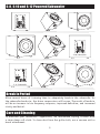
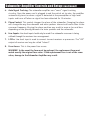
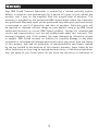
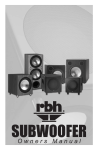
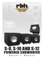
S-8, S-10 AND S-12
POWERED SUBWOOFER
Owner ’s Manual
Introduction
Congratulations on your purchase of an RBH Sound powered subwoofer! Your
subwoofer is the result of many years of research and development dedicated to
producing powerful, accurate bass in home audio systems. This manual contains
operating procedures and specifications. We recommend you thoroughly read
through the material contained in this manual before connecting your subwoofer.
This will ensure you have an understanding of how to setup and operate your
subwoofer for optimum performance.
Important Safety Instructions
The lightning flash with the arrowhead symbol within an equilateral triangle,
is intended to alert the user to the presence of un-insulated “dangerous
voltage” within the product enclosure that my be of sufficient magnitude to
constitute a risk of shock to persons.
The exclamation point within an equilateral triangle is intended to alert the
user to the presence of important operating and maintenance (servicing)
instructions in the literature accompanying the product.
When using your subwoofer, basic safety precautions should always be followed to
reduce the risk of fire, electric shock, and injury.
1. Read and understand all instructions in the users manual before operating the
powered subwoofer.
2. Retain this user manual for future reference.
3. Follow all warnings and instructions in this manual and any marked on the
back of the powered subwoofer.
4. Never touch the woofers or push objects of any kind into the woofer.
5. The powered subwoofer should be connected to a power supply compatible
with the power consumption requirements, see Specifications on page 6.
6. If mounting the powered subwoofer on a stand, the wall, or other device only
do so as recommended by an authorized technician.
7. Place the powered subwoofer a safe distance from all heat sources such as
radiators, stoves, or heaters.
8. Do not operate the powered subwoofer near water—for example, near a
bathtub, kitchen sink or in a wet basement; or a swimming pool.
9. Power supply cords should be routed so they are not likely to be walked on or
pinched by items placed upon or against them.
10. Any service or repair required on the powered subwoofer must be performed
by qualified, authorized technician.
1
S-8, S-10 and S-12 Powered Subwoofer
S-8 Subwoofer
S-10 Subwoofer
S-12 Subwoofer
Break In Period
Allow several hours of listening time to adequately break-in the subwoofer. As
the subwoofer breaks-in, the driver suspensions will loosen. The result of break-in
will be an increase in low frequency response, improved definition, and increased
clarity and detail.
Care and Cleaning
To maintain your subwoofer’s appearance, we recommend wiping it down with
a clean damp soft cloth. To clean dust from the grille cloth, use a vacuum with a
brush attachment.
2
Features
A powered subwoofer is a must-have component for any home theater or audio
system. The performance of your subwoofer can greatly affect the overall
performance of your system. Without a powered subwoofer, the deep bass on your
music CDs and special effects on DVDs may not be heard and/or felt. Think of a
subwoofer as a vital component that adds excitement to your theater or music
experience. The powered subwoofer has its own source of amplification (as opposed
to passive, non-amplified subwoofers which require an additional power amplifier).
Subwoofers can add considerable low-frequency, deep bass performance to any
home theater or audio system.
At the heart of the powered subwoofer is an aluminum cone driver. The driver
material produces enhanced bass definition and accuracy. A powerful magnet,
enhanced suspension and heavy duty voice coil give the driver elevated performance
allowing high output capability and accurate dynamic reproduction.
The powered subwoofer incorporates a class D amplifier with switching power
supply technology, resulting in higher power output, improved bass performance
and maximum energy efficiency.
Variable crossover, adjustable phase control and auto on/off are also used for
convenience and easy integration with other speakers. Audio can be supplied to
the subwoofer by either interconnect (LFE/line level inputs).
Cabinets are constructed from medium density fiberboard because of its inert
properties. The thickness of the front baffle also prevents excess acoustic
radiation. Sophisticated computer modeling and measurement techniques are used
extensively in the powered subwoofer design process.
3
Room Setup Suggestions
In order to obtain the best possible sound from your subwoofer and speaker
system, it is important to determine where the subwoofer and speakers will sound
best in your listening room. Room reflections from the floor, ceiling and side
walls influence the balance, imaging and overall sonic quality at the listening
position. Experiment with placement to determine which location offers the best
overall sound. As a general guide, use the room layout diagram and the following
descriptions when setting up a home theater system. The subwoofer and speakers
shown in the diagram may not always be applicable to your system.
Front Main Speakers
As a starting point, place your left and right tower speakers at least 15 inches
from the wall and 7-feet apart from each other. The distance from the listening
position to each speaker should be close to the distance that separates the two
main speakers. Angling the speakers inward towards the listening position may
give a more spacious and realistic sound stage.
Center Channel Speaker
The center channel speaker should be placed in the center between both left and
right main speakers. Often this positioning dictates placing the speaker either
directly above or below a television monitor. The center channel speaker may be
placed in a horizontal (lying down) or vertical (standing) position.
Rear Surround Speakers
The 2-way bookshelf speakers may be placed either above, behind or to the sides
of the listening position. The listening position should be centered between the
surround speakers. For best performance you may want to experiment with angling
the surround speakers either towards or away from the listening position.
Subwoofer
In order to obtain the best possible sound from your subwoofer, it is important
to determine where the subwoofer will sound best in your listening room. Sound
reflections from the floor, ceiling and side walls influence the balance, imaging
and overall sonic quality at the listening position. Experiment with subwoofer
placement to determine which location offers the best overall sound.
Placement of the subwoofer will largely determine quality, quantity and extension
of the bass frequencies within your listening room. Bass frequencies are reinforced
by close room boundaries. Placing the subwoofer in a corner will make the
subwoofer sound louder and boost the very lowest frequencies.
Placing the subwoofer away from walls will provide the least reinforcement,
making the bass sound subjectively thinner than if the woofer were closer to a
wall. Good results can usually be obtained by placing a subwoofer along a wall
1-3 feet from a corner. Experiment with placement of the subwoofer and the subamplifier controls to achieve the proper bass balance.
4
Room Setup Suggestions (continued)
5
Subwoofer Amplifier Controls and Setup
IMPORTANT NOTICE REGARDING BASS MANAGEMENT: It is important the signal being sent
to the subwoofer be a non-boosted or “flat” signal. Check the settings on your receiver or
processor to make sure any “bass boost”, “super bass” or “loudness” is set to Off. In most
cases a home theater receiver or processor will determine the crossover frequency through
bass management settings. In this configuration, connect the receiver or processor to the
LFE (Low Frequency Effect). Your subwoofer will now reproduce the bass frequencies as they
were originally recorded. Use the subwoofer level control and the individual bass management
control within the receiver or processor to adjust the subwoofers’ volume if necessary. Once
set, the volume controls should not need to be altered as the subwoofers’ volume will track
with the master volume control of your receiver or processor. Use Line Input only if bypassing
your receivers internal processing to deliver a full signal to your subwoofer which is then
managed by the subwoofer’s frequency and volume control.
This section describes the functions and/or use for each of the amplifier controls
located on the back of the subwoofer. Refer to the diagrams on the pages 8 and 9.
1. Voltage Selector Switch: Before connecting the amplifier to any power source
make sure the AC Voltage Selector is set to either 110V or 220V to match the
power voltage in your area.
WARNING! If the voltage setting does not match the AC power supplied, damage to
the Subwoofer Amplifier may result.
2. Volume/Gain Control: The volume/level control should be at the minimum setting
(all the way counter-clockwise) before plugging the subwoofer into an AC wall socket.
Once plugged in, turn the level control up one quarter of a turn (9 o’clock position)
for an initial setting. The level control may be adjusted while playing to match the
subwoofer level with the rest of the system.
IMPORTANT! The volume control should be at the minimum setting (all the way
counter-clockwise) before plugging the subwoofer into an AC wall socket.
3. Crossover Frequency Control: The variable crossover frequency control allows you to
set the low-pass crossover point of the subwoofer anywhere from
40-150 Hz. If using this input experiment with setting the crossover frequency
control at highest setting initially. Increasing the crossover frequency will allow more
mid-bass output from the subwoofer. Decreasing the frequency will allow only deeper
bass from the subwoofer.
NOTE: Read the Important Notice regarding bass management above.
6
Subwoofer Amplifier Controls and Setup (continued)
4. Auto Signal Tracking: The subwoofer amplifier uses “smart” signal tracking
circuitry. Once the power cord is plugged in and the switch set to auto, the amplifier
automatically turns on when a signal is detected at the preamplifier or high level
inputs and turns off when no signal has been detected for 15 minutes.
5. Phase Control: This control changes the phase of the subwoofer. Changing the phase
will change the way the subwoofer and main speakers interact with each other at the
crossover frequency. Varying the phase position may result in more or less mid bass
depending on the phasing between the main speakers and the subwoofer.
6. Line Inputs: Line level input should only be used if no subwoofer crossover is being
utilized through the receivers bass management.
7. LFE In: Line level input is used to connect to most receivers or processors. The “LFE”
output of receiver and may be called “subout”.
8. Fuse Access: This is the power fuse access.
WARNING! In the event the fuse must be replaced, the replacement fuse must
match exactly the original fuse value. If the replacement fuse is not of the same
value, damage to the Subwoofer Amplifier may result.
7
Subwoofer Amplifier Controls and Setup (continued)
S-8 and S-10 Subwoofer Amplifier Diagram.
8
Subwoofer Amplifier Controls and Setup (continued)
S-12 Subwoofer Amplifier Diagram.
9
Specifications
Model
S-8
S-10
S-12
Driver:
8” (203mm) Aluminum
Cone Subwoofer
10” (254mm) Aluminum
Cone Subwoofer
12” (305mm) Aluminum
Cone Subwoofer
Amplifier Type:
Class D
Class D
Class D
Voltage:
110 and 220
110 and 220
110 and 220
Power Handling:
150 Watts
150 Watts
250 Watts
Crossover Frequencies:
40-150Hz (variable)
40-150Hz (variable)
40-150Hz (variable)
Frequencies Response:
32Hz-150Hz (variable)
32Hz-150Hz (variable)
32Hz-150Hz (variable)
LFE Input:
Yes
Yes
Yes
LFE Output:
No
No
Yes
Line Level Input:
Yes
Yes
Yes
Speaker Level Inputs:
No
No
No
Speaker Level Outputs: No
No
No
Phase Control:
Yes (Auto On/Off)
Yes (Auto On/Off)
Yes (Auto On/Off)
Cabinet/Color:
Medium Density Fiberboard (MDF)/Black
Medium Density Fiberboard (MDF)/Black
Medium Density Fiberboard (MDF)/Black
Grille:
Black Cloth
Black Cloth
Black Cloth
Dimensions:
(includes feet and grille)
11” (279mm ) W
12½” (318mm ) H
12¾” (324mm) D
13” (330mm ) W
15½” (394mm ) H
16½” (419mm) D
15¾” (400mm ) W
17¼” (438mm) H
18” (457mm) D
Weight:
19.25 lbs. (8.73 kg.)
33 lbs. (14.97 kg.)
42 lbs. (19.05 kg.)
Warranty:
5 Years/1 Year*
5 Years/1 Year*
5 Years/1 Year*
* Warranty period: 5 years on the cabinet and woofers, and 1 year on the amplifier
10
CAUTION! Before replacing the fuse, disconnect
Situation:
Probable Cause:
Solution:
No sound from
subwoofer(s)
Amplifier is not connected to
constant power outlet.
Make certain the amplifier is plugged
into an unswitched A.C. power outlet.
Amplifier is not receiving an
audio signal from receiver or
processor
Make certain there is an audio signal
from receiver or processor and audio
connections resemble those in the
connections section of this manual.
Amplifier fuse might be blown.
Replace fuse (if fuse is not readily accessible, consult your authorized dealer).
The + and - polarity of the subwoofer wire might be reversed on
the subwoofer.
Check the entire system for proper polarity.
Experiment with the phase switch.
Crossover frequency not adjusted
correctly.
Adjust crossover frequency by turning the
crossover frequency control clockwise until
desired sound is obtained.
L/R line level input is connected
instead of the LFE line level input.
If bass management is enabled on receiver
or processor make sure to use the LFE line
level input. (See amplifier controls and
setup on the previous page.)
Performance is less
than expected
11
Warranty
Your RBH Sound Powered Subwoofer is covered by a limited warranty against
defects in materials and workmanship for a period of 5 years on the cabinet and
woofers, and 1 year on the amplifier from the original date of purchase. This
warranty is provided by the authorized RBH Sound dealer where the subwoofer
was purchased. Warranty repair will be performed only when your purchase receipt
is presented as proof of ownership and date of purchase. Defective parts will
be repaired or replaced without charge by your dealer’s store or by RBH Sound
authorized locations to service RBH Sound products. Charges for unauthorized
service and transportation cost are not reimbursable under this warranty. This
warranty becomes void if the product has been damaged by alteration, misuse
or neglect. RBH Sound assumes no liability for property damage or any other
incidental or consequential damage whatsoever which may result from the failure
of this product. Any and all warranties of merchantability and fitness implied
by law are limited to the duration of this express warranty. Some states do not
allow limitations on how long an implied warranty lasts, so the above limitations
may not apply to you. Some states do not allow the exclusion or limitation of
12
TM
Redefining The Way You Experience Sound.
382 Marshall Way, Layton, Utah • USA • 84041
Toll Free: (800) 543-2205 • Fax: (801) 543-3300
www.rbhsound.com
It is RBH Sound policy to continuously incorporate improvements into products; all specifications are subject to change without notice.
Copyright © 2013 RBH Sound. All Rights Reserved. 02012013