1
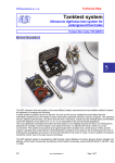
Serial Link Gateway RS-422/Current Loop Converter User Manual Hardware specifications & installation P DOC SLG 001E V11 This page is intentionally left blank Introduction The Serial Link Gateway is a RS-422/Current loop converter. The Serial Link Gateway is fully compliant with the EN50155 standard for railway systems. This user manual describes all the necessary information to getting started with the Serial Link Gateway hardware. Prerequisites It is necessary that the user has got technical knowledge in mechanical & electrical railway systems. Safety instructions Following symbols are used in this documentation in order to avoid user for potential risks: Risk of personal injury or damage to the equipment. Risk of an electrical hazard. Intellectual Property Leroy Automation owns the sole industrial and intellectual property of the products. The company Leroy Automation maintains and regularly improves its hardware and software products. The information contained in the document herein may be altered, removed or modified without prior notice, and this does not engage the responsibility of the company. This user manual cannot be released, copied or duplicated in any forms without the written authorization issued by Leroy Automation. Contact Leroy Automation 35 Boulevard du Libre Echange 31650 SAINT-ORENS FRANCE +33 562 240 550 +33 562 240 555 mailto:[email protected] http://www.leroy-automation.com support technique : +33 562 240 546 mailto:[email protected] This page is intentionally left blank Table of Contents Chapter 1 Introduction ...................................................................................... 1 Contents ................................................................................................................ 1 Hardware Description ............................................................................................... 1 Product part numbers .............................................................................................. 1 Architecture ............................................................................................................ 2 Chapter 2 Specifications .................................................................................... 3 Contents ................................................................................................................ 3 General Specifications .............................................................................................. 3 Standards ............................................................................................................... 3 Electric specifications ............................................................................................... 5 Power supply................................................................................................... 5 RS422 ............................................................................................................ 5 Current Loop ................................................................................................... 5 Coding ........................................................................................................... 6 Baud rate ....................................................................................................... 6 Mechanical specifications .......................................................................................... 7 Dimensions (unit : mm) ................................................................................... 7 External connectors ......................................................................................... 7 RS422 Connector ..................................................................................... 7 Current Loop Connector ............................................................................ 8 Power supply Connector ........................................................................... 8 Chapter 3 Wiring................................................................................................ 9 Contents ................................................................................................................ 9 Connectors Pinout .................................................................................................... 9 Power supply connector Pinout .......................................................................... 9 Terminal block RS422 connector pin-out ............................................................. 9 Terminal block Current Loop connector pin-out ...................................................10 Chapter 4 Mounting, installation & environmental compatibility...................... 11 Contents ...............................................................................................................11 Mounting ...............................................................................................................11 Mounting procedure ........................................................................................11 Required tools ................................................................................................12 Tightening torque ...........................................................................................12 Installation ............................................................................................................12 Cables ...........................................................................................................13 Grounding connection .....................................................................................14 Environmental compatibility and disposal ...................................................................14 Introduction This page is intentionally left blank Introduction Chapter 1 Introduction Contents In this section, we will discuss the following topics: Hardware description, Product part numbers, Architecture Hardware Description The Serial Link Gateway is a hardware unit fully compliant with the EN50155 standard, and it is designed to be integrated in embedded railway systems and subsystems. Protection enclosure Current Loop DSUB connector Diagnostic LEDs Rail TH35 adaptor RS422 DSUB connector Power supply 2 poles connector Product part numbers Part number P SLG 002 Range name Serial Link Gateway Power supply RS422 Current Loop P DOC SLG 001E V11 24 VDC (16.8V to 30V) Bidirectional port full duplex mode 0-20mA current loop Page 1 Introduction Architecture Architecture example for a Serial Link Gateway reference P SLG 002: SUBD-9 F Current Loop Rx Tx LEDs RS422 Rx Tx LEDs SUBD-9 M POWER LED POWER SUPPLY P DOC SLG 001E V11 Page 2 Specifications Chapter 2 Specifications Contents In this section, we will discuss the following topics: General specifications Standards Electric specifications Mechanical specifications General Specifications Dimensions Weight Covers Degree of protection Startup time Operating temperature Storage temperature Relative Humidity Fire/Smoke MTBF Interfaces RS422 Current Loop Power supply & IO Diagnosis LEDs 34 x 105 x 117 (width x height x depth) 0,4kg Aluminium alloys IP40 <10ms Class T3 (-25 +70°C) -40°C /+70°C +55°C 95% humidity 48 hours (NF EN 60068-2-30 - Criteria A) EN 45545-1 & 2 compliant (HL3) 2 450 000 Hours 1 x D-Sub9 male connector type Class 1 1 x D-Sub9 female connector type Class 1 Base strip - MSTB 2,5/ 2-GF-5,08 2 x LEDs for RS422 Tx/Rx status 2 x LEDs for CL Tx/Rx status 2 x LEDs for Power Supply status Standards Main standards Number Date Designation NF EN 50155 2007-10 Railway applications - Electronic equipment used on rolling stock. IRIS 02 2009 International Railway Industry Standard. NF EN ISO9001 2008-11 Quality management systems. NF EN 50121-3-2 2006-11 Railway applications - Electromagnetic compatibility - Part 3-2: Rolling stock - Apparatus. NF EN 50121-5 2001-01 Railway applications - Electromagnetic compatibility - Emission and immunity of fixed power supply installations and apparatus. P DOC SLG 001E V11 Page 3 Specifications Number Date Designation EN 45545-1 EN 45545-2 2013 Railway application - Fire protection on railway vehicles Part 1 : General – Railway applications Part 2 : requirements for fire behavior of materials and components – Railway applications NF ISO2859-1 2000-04 Sampling procedures for inspection by attributes - Part 1: Sampling schemes indexed by acceptance quality limit (AQL) for lot-bylot inspection. IEC 62380 2004 Reliability data handbook - Universal model for reliability prediction of electronics components, PCBs and equipment. Mechanical tests Number Date NF EN 61 373 2011 Designation Level Railway applications Rolling stock equipment - Shock and vibration tests. Chocs: 50m/s² XYZ - 30 ms Criteria A Endurance: 7.9m/s² XYZ – 150Hz 5 hours Climatic tests Number Date Designation Level NF EN 60068-2-1 2007 Cold storage -40°C 16 hours A NF EN 60068-2-1 2007 Cold start -40°C A NF EN 60068-2-2 2007 Hot test +70°C A NF EN 60068-2-30 2007 Damp test +55°C 95% humidity 48 hours A NF EN 50155 Salt mist 96 hours A 2007 Criteria EMC tests Number Date Designation NF EN 61000-4-2 2009 ESD NF EN 61000-4-3 2011 Immunity Radiated RFI 80 MHz … 1 GHz : 20V/m 1.4 GHz … 2.1 GHz : 10V/m 2.1 GHz … 2.5 GHz : 5V/m A NF EN 61000-4-4 2010 Fast burst 2 kV direct A NF EN 61000-4-5 2007 surge 2 kV MC 1 kV MD A NF EN 61000-4-6 2009 Immunity conducted RFI 10V RMS A NF EN 55011 P DOC SLG 001E V11 2011 Measuring radiated emissions Level Enclosure contact : 6 kV Enclosure air : 8 kV Criteria B 150 kHz … 500 kHz 99dBµV 500 kHz … 30 MHz 93dBµV 30 MHz … 230 MHz 47dBµV/m at 3m 230 MHz … 1 GHz 47dBµV/m at 3m Page 4 Specifications Electric specifications Power supply Input specifications Nominal supply voltage range Extended supply voltage range Reverse polarity protection Overvoltage protection Inrush current limitating Low voltage protection Fuse 24VDC 16.8VDC to 30VDC Yes Yes <3xIn during 20ms Startup only for U>16,8VDC 1.4x24V=33.6V : normal running 0.6x24V=14.4V : normal running during 100ms gradual decline (from nominal to 0V) : support 1V/5min Micro-switching at nominal voltage : 10ms No Consumption <10W Displaying 2 LEDs (green) 1500 VDC to ground 1500 VDC to CL 1500 VDC to RS422 Resistance to voltage interferences Insulation RS422 Supported modes Working mode Terminating Polarization Insulation Displaying EIA/TIA-422 standards Full duplex TXA/TXB- RS485: no resistor RXA/RXB- RS485: resistor (120) TXA and TXB- RS485: no resistor RXB/0V RS485: resistor (1000) RXA/5V RS485: resistor (1000) 750 VDC to ground 1500 VDC to CL 1500 VDC to POWER SUPPLY 2 LEDs (green) one for Tx and one for Rx Current Loop Transmission Active Reception Active Maximum voltage in open loop 30 VDC Tx Logic level "0" [0 mA.to.0.5 mA] Tx Logic level "1" [18.1 mA.to.22.7 mA] Working mode levels Rx Logic level "0" [0mA.to.10.4mA] Rx Logic level "1" [10.9mA.to.24mA] 750 VDC to ground Insulation 1500 VDC to RS422 1500 VDC to POWER SUPPLY Displaying P DOC SLG 001E V11 2 LEDs (green) one for Tx and one for Rx Page 5 Specifications Coding logical FALSE: Current Loop Rx : 0mA = SPACE ; RS422 Rx+ - Rx- >0 logical TRUE: Current Loop Rx : 20mA = MARK ; RS422 Rx+ - Rx- <0 Baud rate Up to 38400 bits/s Lag : RX RS422 TX CL : 15.6 µs Lag : RX CL TX RS422 : 2.5 µs P DOC SLG 001E V11 Page 6 Specifications Mechanical specifications Dimensions (unit : mm) External connectors SUBD 9 pts with gilded crimp contacts Class 1 with cover locking with screws 4-40 UNC shall be used. RS422 Connector Preferential references are given below: Description D-Sub crimp 9-pole female assembly D SUB FE turned contact AWG 18-22_PL1 Crimp contacts female AWG 24-20 Crimp contacts female AWG 18 Full metal hood 9P T&S entry H UNC 4-40 Full metal hood 9P S40° entry. H UNC 4-40 P DOC SLG 001E V11 Part Number HARTING 09 67 009 4701 09 67 000 3476 NA NA 61 03 001 2010 61 03 001 2013 Part Number INOTEC DC09S-G NA DCC2S4 DCC2S5 DG09MS-80 DG09MS-1-80 Page 7 Specifications Current Loop Connector Preferential references are given below: Description D-Sub crimp 9-pole male assembly D-Sub, MA AWG 18-22 crimp con Crimp contacts male AWG 24-20Crimp contacts male AWG 18Full metal hood 9P T&S entry H UNC 4-40 Full metal hood 9P S40° entry. H UNC 4-40 Part Number HARTING 09 67 009 5601 09 67 000 3576 NA NA 61 03 001 2010 61 03 001 2013 Part Number INOTEC DCE09P-G NA DCC2P4 DCC2P5 DG09MS-80 DG09MS-1-80 Power supply Connector Preferential references are given below: Description Printed-circuit board connector- Plug Module female contact for conductors from 0.5 to 1.0 mm² Module female contact for conductors from 1.5 to 2.5 mm² P DOC SLG 001E V11 Type Phoenix Contact MSTBC 2,5/ 2-STZF5,08 MSTBC-MT 0,5-1,0 MSTBC-MT 1,5-2,5 Part Number Phoenix Contact 1809734 3190564 3190551 Page 8 Wiring Chapter 3 Wiring Contents In this section, we will discuss the following topics: Connectors Pinout Connectors Pinout Power supply connector Pinout Designation Pins + 24V 1 0V 2 Front view Terminal block RS422 connector pin-out P DOC SLG 001E V11 Page 9 Wiring Example of Terminal block RS422 wiring: (TXA) (TXB) (TXA) (TXB) (RXB) (RXA) (RXB) (RXA) Terminal block Current Loop connector pin-out Example of Terminal block Current Loop wiring: P DOC SLG 001E V11 Page 10 Mounting, installation & environmental compatibility Chapter 4 Mounting, installation & environmental compatibility Contents In this section, we will discuss the following topics: Mounting Installation Environmental compatibility and disposal Mounting Mounting procedure With the Serial Link Gateway unit inclined at 10 °, put the spring of the rail DIN adaptor below the edge of the rail. Lift up the Serial Link Gateway unit by compressing the spring then rotate him for as the adaptor clip will lock on the top edge of the DIN rail. P DOC SLG 001E V11 Page 11 Mounting, installation & environmental compatibility Then the Serial Link Gateway unit is ready to work. Required tools No tool is necessary in order to mount or dismount the Serial Link Gateway on its rail. A screwdriver is necessary to mount or dismount D-sub connectors on Serial Link Gateway. Tightening torque Element Recommended tightening torque D-sub connector device screws 0.4 to 0.5 Nm Power connector device screws 0.4 to 0.5 Nm Installation NOTICE Chapter 5 Grounding of the Serial Link Gateway! Danger of electrical discharge as a result of a missing ground connection. ● shall be connected to ground pin to the rear of the housing. NOTICE Serial Link Gateway mounting or dismounting must be done unpowered. P DOC SLG 001E V11 Page 12 Mounting, installation & environmental compatibility Cables The connectors required for assembly of the cables are available as accessories. Cable with D-sub connector Only use cables AWG20/AWG24 to assemble the cables with D-sub connectors. Screened data transmission cable mit PE Example: core insulation, 7-wire strands and twisted UNITRONIC® Li2YCY (TP) ref: pairs (100 Ohms-120 Ohms) 0031321 (6xAWG24) Flexing: - 5˚C up to +70˚C 0031326 (6xAWG22) Fixed installation: - 40˚C up to +80˚C 0031331 (6xAWG20) Flame retardant acc. to IEC 60332-1-2 Mount a female D-sub connector at each end of the cable for RS422 liaison. Mount a male D-sub connector at each end of the cable for Current Loop liaison. Note: For correct EMC protection it is recommended that the shield of the transmission cable must be directly connected to the metal hood of each D'SUB connector. The following applies to cables with D-sub connectors: Maximum permissible cable length of an individual cable: 100 m. Pin assignments refer to Chapter 3. Cable for power supply The power supply cable shall be connected to the Serial Link Gateway through a 2 female pole 5.08 plug connector type. Only use cables AWG16/AWG20 to assemble the cables with MSTBC plug type. MSTBC 2,5/ 2-STZF-5,08 plug MSTBC 2,5/ 2-STZF-5,08 dimensions Pin assignments refer to Chapter 3. P DOC SLG 001E V11 Page 13 Mounting, installation & environmental compatibility Grounding connection The Serial Link Gateway shall be connected to electrical ground by its ground pin to the rear panel of the housing. Preconized Earth Bonding Straps: Earth Bonding Strap example Features: Circular tinned copper braid leads. Both ends fitted with integral lug terminations. Conductor sectional area ≥ 5 mm2 (AWG 10 or less) Maximum length 250 mm. Mounting parameters: Stud Size M4 with HEXAGONAL NUT ISO 4032 - M4 (Hex socket 7 - Torque 1.5 to 2 Nm) Environmental compatibility and disposal This device is manufactured using materials and procedures which comply with current environmental protection standards as best as possible. More specifically, the following measures have been undertaken: Use of reusable materials Use of halogen-free plastics Electronic parts and synthetic materials can be separated Electronic parts and batteries must not be disposed of with domestic waste. P DOC SLG 001E V11 Take electronic parts and batteries to local collection points or recycling centers. Contact local authorities for more information. Observe national requirements for disposing of electronic parts and batteries. Page 14