1
Copyright ○,C2006 MEKICS Co., Ltd.
All rights reserved
MEKANT
Ventilator
User Manual
System
MEKICS Co., Ltd.
5F, A-BLDG,WooLimLion, #144-3, Sangdaewon-dong,
Jungwon-gu, Seongnam-si, Gyeonggi-do, Korea 462-725
TEL : +82-70-7119-2500
0470
FAX : +82-31-735-2761
URL : http://www.mek-ics.com
0
Ventilator User’s Manual
Definitions
This operator’s manual uses three special indicators to convey information of a
specific nature. They include :
Warning
Indicates a condition that can endanger the patient or the ventilator
operator.
Caution
Indicates a condition that can damage the equipment.
NOTE :
Indicates points of particular emphasis that make operation of the
ventilator more efficient or convenient.
CONTENTS
Operator’s Guide
1 Introduction ………………………………………………………………
9
1.1 Warnings and Cautions ………………………………………
9
1.1.1 Warning ………………………………………………….
9
1.1.2 Caution …………………………………………………..
11
1.2 General description ……………………………………………
15
1.2.1 Front picture and the explanation …………………….
16
1.2.2 Back side picture and explanation ……………………
18
1.2.3 Left side picture and explanation ……………………..
20
1.2.4 Right side picture and explanation ……………………
21
1.3 Specifications ………………………………………………….
22
1.3.1 Features …………………………………………………
22
1.3.2 Electrical Specifications ………………………………..
22
1.3.3 Functional Specifications ………………………………
23
1.3.4 Pneumatic Specifications ………………………………
29
1.3.5 Physical data ……………………………………………
29
1.3.6 Environmental data …………………………………….
30
1.4 Standards and safety requirements …………………………
30
1.4.1 Standards and safety requirements …………………..
30
1.5 Symbols …………………………………………………………
31
1.5.1 Description of Symbols …………………………………
31
1.6 Maintenance ……………………………………………………
35
2. Installation and set up …………………………………………………...
37
2.1. Installation …………………………………………………….
37
2.2. External electrical supply …………………………………….
37
2.2.1 AC description ………………………………………………
37
2.2.2 External battery …………………………………………….
38
MV2000
Ver. 3.7
2.3 Internal battery …………………………………………………
40
2.3.1 Internal battery Indicator ………………………………
41
2.3.2 How to change internal battery ……………………….
42
2.4 Oxygen and Air supply ………………………………………..
43
2.5 Filters ……………………………………………………………
44
2.6 Transportation ………………………………………………….
45
2.7 Fuse replacement instruction …………………………………
45
3. Operating instructions …………………………………………………..
47
3.1. Front panel ……………………………………………………
47
3.1.1 Rotational Control Knob ………………………………
47
3.1.2 Alarm lamp …………………………………………….
47
3.1.3 Keypad …..…………………………………………….
48
3.1.4 LED Indicator …………………………………………..
51
3.2 Operating……………………………………………………….
52
3.2.1 Operating procedure and how to use………………..
52
3.3 Display ………………………………………………………….
54
3.3.1 Status information ……………………………………..
55
3.3.2 Measurement information …………………………….
56
3.3.3 Waveform and alarm status …………………………..
57
3.3.4 Setting information ……………………………………..
58
3.4 Menu …………………………………………………………….
59
3.4.1. VENT Mode ……………………………………………..
60
3.4.1.1 VACV …………………………………………….
62
3.4.1.2 VSIMV ……………………………………………
65
3.4.1.3 SPONT …………………………………………
68
3.4.1.4 PACV …………………………………………….
71
3.4.1.5 PSIMV ……………………………………………
74
3.4.1.6 TBILEVEL …………………………………………
77
3.4.1.7 NIV …….………………………………………..
81
3.4.1.8 PRVC …………………………………………..
83
3.4.1.9 AUTO …………………………………………...
85
1
Ventilator User’s Manual
MV2000
Ver. 3.7
3.4.2 Alarm set …………………………………………………
86
3.4.3 Trend Mode ……………………………………………..
88
3.4.4 SYSTEM SETUP …………………………………………….
90
3.4.4.1 SOUND…………………………………………..
91
3.4.4.2 NEBULIZER ………………………………………
92
3.4.4.3 Graph SETUP ……………………………………… 93
3.4.4.4 User SETUP………………………………………
95
3.4.4.5 SYSTEM SETUP…………………………………..
104
4. Alarms ………………………………………………………………..………………
111
4.1 General Information ……………………………………………. 111
4.2 Alarm Massage………………………………………………….. 112
Appendix ………………………………………………………………….…………….
113
A. Operating theory …………………………………………………. 114
B. Communications …………………………………………………. 117
C. Parts accessories ………………………………………………… 120
Service Calls ………………………………………………………………………….
2
Ventilator User’s Manual
122
MV2000
Ver. 3.7
Introduction
SECTION
1
This operator’s manual explains the way of installation and usage for MEKANT.
Notice for use explains general information to be careful while using the product and
other notices are written with each function. Users are recommended to be aware of
notice for use and all menus before using the product.
This operator’s manual is allowed to use by doctors or authorized persons who are
permitted to use, or designed to use by qualified and trained persons for using this
products.
Service, test, correction and main continuous working will be written in service manual
of MEKANT Ventilator. However, service manual is allowed to be possesed by
authorized persons by MEKICS.
1.1 Warnings and Cautions
1.1.1 Warning
Please make sure to use MEKANT by authorized persons and read the manual before
use.
Check the setting figure of various sensors and devices before use. Users shall
check out whether the environment is OK before use.
Please be aware of the manual provided by the manufacturer when it is used or kept.
Do not use it near inflammable anesthetic to avoid any possible explosion.
Do not disassemble or open the main body to avoid electrical impulse. Disassembly of
the equipment shall be allowed by service staffs approved by MEKICS Co., Ltd.
Users shall be careful with circuit joint to be connected with patients.
3
Ventilator User’s Manual
MV2000
Ver. 3.7
1
Instruction
Always shall be careful with leakage of electrical current and consult with hospital
technical engineer if any doubt.
In case of abnormal working or any damage in the equipment, it shall not be used for
patients.
Do not touch patient, table or the equipment if a defibrillator is used.
Disposable stuffs and disposable circuit for patients shall not be reused.
Reusable stuffs used for patients shall be sterilized or washed for reuse.
Check out the level before setting alarm. Alarm limitation shall be done for the current
selected group. Alarm setting can be changed by level change.
Do not correct calibration while used for patient. Please correct it after disconnection
from patient if any doubt.
Insulate power source in case that the equipment is wet and call a hospital technical
engineer.
Please connect earth cable to earth connection port to protect patients and the product.
Do not disassemble the product in any case.
Do not install the various kinds of sensor to patients too strongly and not to be
entangled.
Do not reuse it if you find this symbol
on the accessory, which means disposable
stuff.
MEKANT shall be tested regularly if it is working in normal condition.
4
Ventilator User’s Manual
MV2000
Ver. 3.7
1
Instruction
Accessories are aseptic products, so the package shall not be torn before use and
products shall be free from any defects or cracks.
1.1.2 Caution
MEKANT as respiration assistant equipment for adult helps for normal breathing by
setting breathing way, breathing volume, breathing times, oxygen density, breathing
rate etc in order to solve hypoxia to be appeared from emphysema of the lungs patients
or respiratory disease patients. It is a respiration assistant equipment with various
alarm function and safety device for safe respiration management, but above all,
should be used together with other clinical information for patients’ safety and
diagnosis.
Avoid the place where there is moisture.
Do not handle the equipment with wet hands.
Avoid the place under direct rays.
Use the equipment within the limits of temperature 10 ~ 40 centigrade and humidity
30 ~ 75%
Do not place the equipment near electronic heater.
Do not place the equipment under high humidity and bad ventilation.
Do not place the equipment where it is possible to take vibration or sudden impulse.
Do not place the equipment where to be damaged by explosive gas or chemicals.
Protect the equipment from dust or metal scrap.
5
Ventilator User’s Manual
MV2000
Ver. 3.7
1
Instruction
Pull out power code with plug grasped, instead of cable.
Check out the main equipment and sensor at the same time after cleaning the
equipment. Do not use if there is any damage in the equipment.
Make the cable and sensor clean after use. Clean them by towel with alcohol soaked
and do not use benzene or gasoline.
Do not use the equipment in dangerous place. Always be careful with the possibility of
bad influence by environment.
It is possible to be flew more current than allowed when the assistant device is used.
Consult with hospital engineer or authorized local dealer.
Check out the basic auxiliary device regularly. Do not use a damaged or electrical
unstable device. Consult with hospital engineer if any doubt.
Do not use the goods beyond standard certified one. This product shall be used under
standard certification. Manufacturer does not take responsibility for the problem
occurred while using the product beyond standard certification.
The product can be disassembled by educated and authorized staffs. If a user violates
this item, after sales service is not provided.
Do not install the various kinds of sensor to patients too strongly and not to be
entangled.
Do not place the product where it is possible to fall to a patient.
Do not move the equipment when power code or high pressure hose cage is connected.
It will be harmed for patient or the equipment has an error by itself
6
Ventilator User’s Manual
MV2000
Ver. 3.7
1
Instruction
If a measured figure is turned out not to be correct, consult with hospital engineer or
authorized local dealer.
Connect the equipment isolated from other devices electronically for patients’
electrical safety.
Accessories of MEKANT shall be used with the ones provided by MEKICS or
MEKICS’s designated dealer or listed in the manual. MEKICS or MEKICS’s
designated dealer provide standard certified products only.
MEKANT shall be tested regularly if it is working well.
Turn off main switch located backside of the product after use.
Place the product in stable position.
Use the sensor and cable provided and designated by manufacturer, and consult with
hospital engineer or authorized local dealer if you want to use other products.
Replace the disposable sensor after use.
Sep up the equipment when it is needed.
Minimize patient’s move when it is used.
Make high pressure hose and cable clean after use. Clean them by towel with alcohol
soaked and do not use benzene or gasoline.
7
Ventilator User’s Manual
MV2000
Ver. 3.7
1
Instruction
The Oxygen Air pressure which is impressed pneumatic block should be between 35PSI
and 90PSI. Otherwise, it would affect the equipment.
Move the equipment with fastened to avoid any possible damage to other products or
people by the monitor or cable.
Basically, MEKANT is designed not to have functional disorder by surrounded
electronic wave. But, it is possible to be occurred any disorder due to high frequency of
surrounding. It may be possible to calculate wrong figure, lose present figure or show
noisy wave. Please ask MEKICS technical service center or local distributor if you
need help.
Please turn off the power to recharge the battery when it is not used.
MEKANT ventilator system is a product conforming to Class II b.
8
Ventilator User’s Manual
MV2000
Ver. 3.7
1
Instruction
1.2 General Description
MEKANT as respiration assistant equipment for adult helps for normal breathing by
setting breathing way, breathing volume, breathing times, oxygen density, breathing
rate etc in order to solve hypoxia to be appeared from emphysema of the lungs patients
or respiratory disease patients.
It is a respiration assistant equipment with various alarm function and safety device
for safe respiration management, but above all, should be used together with other
clinical information for patients’ safety and diagnosis
9
Ventilator User’s Manual
MV2000
Ver. 3.7
1
Instruction
1.2.1 Front picture and the explanation
10
Ventilator User’s Manual
MV2000
Ver. 3.7
1
Instruction
No.
Part
Description
ⓐ
Circuit Arm
Install Circuit Arm for patient.
ⓑ
LCD Monitor
Show the condition of various ventilators and patients.
ⓒ
Key Pad
Key button and encoder.
ⓓ
Inspiration Connector
Joint hole to connect to patient.
ⓔ
Expiration Connector
Joint hole to connect from patient.
ⓕ
Expiration Lever
Lock or unlock lever for Expiration Assembly.
ⓖ
Carriage Grip
ⓗ
Nebulizer Port
Connection to spray medicines
Warning
Be careful because heated exhalation assembly due to moisture
during exhalation.
11
Ventilator User’s Manual
MV2000
Ver. 3.7
1
Instruction
1.2.2 Back side picture and the explanation
12
Ventilator User’s Manual
MV2000
Ver. 3.7
1
Instruction
No.
Part
Description
ⓐ
Speaker
For alarm and sound.
ⓑ
VGA
VGA cable connection hole to show patient condition on the
other Monitor.
COMM
Cable connection hole to connect PC or central connection.
To Pneumatic
Connection hole to connect to the main body.
ⓒ
AC Inlet
Connection hole for AC power input.
ⓓ
External Battery
Connection hole for external battery.
ⓔ
Power Switch
Power on/off switch for common use.
ⓕ
O2 Inlet
Connection hole to connect to main body using high pressure
hose to approve O2 gas.
ⓖ
Connection hole to connect to the main body, using high
Air Inlet
pressure hose to approve air gas. Device to filter the moisture in
the Air.
ⓗ
Tank Relief
Outlet to exhaust the over pressed air when the pressure of air
tank is over than 40 PSI.
ⓘ
Battery Replacement
Door to replace the internal battery.
Door
ⓙ
To Monitor
Connection for monitor.
ⓚ
COMM
Connection hole for pneumatic communication.
Warning
You should be careful with battery’s polarity when it is exchanged.
Products can be damaged when polarity is connected wrongly.
It should be careful of battery’s terminal to be short on the metal part
13
Ventilator User’s Manual
MV2000
Ver. 3.7
1
Instruction
1.2.3 Left side picture and the explanation
ⓐ LOCKER
ⓐ LOCKER
Locker to disassemble main body with cart.
Pull to unlock and push to lock.
14
Ventilator User’s Manual
MV2000
Ver. 3.7
1
Instruction
1.2.4 Right side picture and the explanation
ⓐ O2 CHANGE DOOR
ⓑ INSPIRATION
RELIEF
ⓐ O2 Exchange Door
Door to be used for exchanging O2 Sensor.
ⓑ Inspiration Check
Safety valve to exhaust by software, hardware and
Valve
mechanically when the equipment is out of order.
Warning
Do not stop up safety valve to exhaust by software, hardware and
mechanically when the equipment is out of order.
15
Ventilator User’s Manual
MV2000
Ver. 3.7
1
Instruction
1.3 Specifications
1.3.1 Features
User friendly POP-up Menu with rotary and push/pull Encoder.
100% O2, Inspiration Pause, Expiration Pause, Key-Lock ,
Manual and/or Auto Nebulizer
Dual Alarm ( Speaker / Buzzer ) system
External battery ( for Mobile application )
1.3.2 Electrical Specifications
AC input voltage
100 - 120 VAC, 10A 50/60 Hz
200 - 240 VAC, 5A 50/60 Hz
AC input FUSE Rating
250V/6.3A
Power consumption
84 W max
External DC input voltage
12V @ 7A Pb battery
Internal battery
Battery ; 12V / 7A Pb battery
Operating time: 3 hours minimum .
Recharge time; 4 Hours max.
Please change it after 2 years use.
It can be used for 30 minutes normally. On the
other hand, it will be more than 30 minutes if
power consumption is small.
Communication
Central interface ; RS-232 serial interface
Baud rate 115,200bps,
Upgrade (Main board, Pneumatic board)
Display
10.4” LCD monitor,
640*480,
16
Ventilator User’s Manual
MV2000
Ver. 3.7
1
Instruction
1.3.3 Functional Specifications
MODE
V-ACV
Volume Assist Controlled Ventilation
Controlling patient’s mechanical artificial respiration based on air
volume and adjusting inspiration and exhalation time by force.
V-SIMV
Volume based Synchronized Intermittent Mandatory Ventilation
Controlling artificial respiration based on air volume in accordance
with patient’s voluntary respiration.
SPONT Spontaneous Ventilation
Giving pressure support centering around voluntary respiration.
P-ACV
Pressure based Assistance Controlled Ventilation
Controlling patient’s mechanical artificial respiration based on
pressure.
P-SIMV
Pressure based Synchronized Intermittent Mandatory Ventilation
Controlling artificial respiration based on pressure in accordance
with patient’s voluntary respiration.
T-BILEVEL
Same as SPONT and exist Upper PEEP (Refer to SPONT mode)
NIV
Non Invasive Ventilation
During artificial respiration by mask type, not tubing type, PACV
working in allowance of air leakage. (Refer to PACV mode)
PRVC
Pressure Regulated Volume Controlled Ventilation
Breaths are delivered mandatorily with a constant flow to assure
present volumes.
AUTO
Quick start according to body weight. (Working in PACV mode)
17
Ventilator User’s Manual
MV2000
Ver. 3.7
1
Instruction
SETTING PARAMETER
Setting range
BW
3 kg ~ 150 kg
Pressure
5 ~ 80 cmH2O
Condition
Default
10ml/kg
±(1.7 + 4% of the actual
30 cmH2O
reading) cmH2O
time 0 ~ 2 sec
Plateau
0.1 sec
(pause)
0 ~ 45 cmH2O
PEEP
±(1.7 + 4% of the actual
3 cmH2O
reading) cmH2O
High PEEP
5 ~ 45 cmH2O
±(1.7 + 4% of the actual
+15 cmH2O
reading) cmH2O
Low PEEP
0 ~ 45 cmH2O
±(1.7 + 4% of the actual
+3 cmH2O
reading) cmH2O
High PEEP time
0.2 ~ 24 sec
Low PEEP time
Infinite
1 sec
±10 %
Setting range
Condition
Default
Inspiration time
0.2 ~ 9.9 sec
±10 %
1 sec
Fend
25 ~ 100 %
100 %
Rise
SLOW,MID,FAST
MID
E-sense %
10 ~ 60 %
30 %
Pressure Support
0 ~ 45 cmH2O
±(1.7 + 4% of the actual
0 cmH2O
reading) cmH2O
Trigger
sensitivity 0.5 ~ 20 cmH2O
±(1.7 + 4% of the actual
Pressure
Trigger
reading) cmH2O
sensitivity 0.5 ~ 20 L/min
±15 % (VMIN>3lpm)
5 lpm
±0.5lpm (VIMIN≤3lpm
Flow
Volume
5 cmH2O
5 ml ~ 2500 ml
±15 % (VTIDAL>100ml)
10 ml/kg
±20ml (VTIDAL≤100ml)
Rate
2 ~ 120 bpm
±2 bpm
20 bpm
O2 %
21 ~ 100 %
±3 %
30 %
18
Ventilator User’s Manual
MV2000
Ver. 3.7
1
Instruction
Nebulizer
Setting range
Default
10 ~ 180 min
off
Limited 200ml
Flow trigger
base flow can not use
Inspiration pause
Resistance measurement
off
Expiration pause
Compliance measurement
off
Manual Inspiration
Setting tidal volume
off
100% O2
2 minutes
off
Key lock
Function key lock
off
QUICK RUN (Emergency Start Ventilation)
O2
Setting range
1:2
60 %
Mode
PACV
Inspiration Pressure
25 cmH2O
Inspiration time
1 sec
Expiration time
2 sec
Respiration rate
20 bpm
PEEP
3 cmH2O
Trigger type
Pressure type
Trigger sensitivity
3 cmH2O
Rise %
50 %
E-sense
30 %
I:E
19
Ventilator User’s Manual
MV2000
Ver. 3.7
1
Instruction
Alarms
High tidal volume
Setting range
5 cmH2O ~ 120 cmH2O
0 cmH2O ~ 50 cmH2O
20 ml ~ 2500 ml ,OFF
Low tidal volume
0 ml ~ 2500 ml
High minute volume
1 ~ 99L
Low minute volume
0 ~ 98L
High respiration rate
2 ~ 120 bpm
Leak volume
10 ~ 500 ml
Apnea
OFF, 10 ~60 sec
O2 % high
21~100%,OFF
Power loss
AC/DC power loss
High pressure
Low pressure
Low Air/O2 pressure
Obstructed tube
Airway leak
Vent in-operation
Open Circuit
20
Ventilator User’s Manual
MV2000
Ver. 3.7
1
Instruction
DISPLAY PARAMETER
● VACV MODE, VSIMV MODE
No.
Item
Range
Unit
Condition
ⓐ
VTIDAL
0~4000
ml
±15 % (VTIDAL>100ml), ±20ml (VTIDAL≤100ml)
ⓑ
ViTIDAL
0~2500
ml
±15 % (ViTIDAL>100ml), ±20ml (ViTIDAL≤100ml)
ⓒ
VMIN
0~180
LPM
±15 % (VMIN>3LPM), ±0.5LPM (VMIN≤3LPM)
ⓓ
RRESP
0~150
BPM
±1.0 %
ⓔ
PPEAK
0~85
cmH2O
±(1.7 + 4% of the actual reading) cmH2O
ⓕ
PMEAN
0~85
cmH2O
±(1.7 + 4% of the actual reading) cmH2O
ⓖ
PPAUSE
0~85
cmH2O
±(1.7 + 4% of the actual reading) cmH2O
ⓗ
PEEP
0~50
cmH2O
±(1.7 + 4% of the actual reading) cmH2O
ⓘ
O2
21~ 100
%
±2.0 %
ⓙ
I:E RATIO
ⓚ
sVmin
0~180
LPM
±15 % (VMIN>3LPM), ±0.5LPM (VMIN≤3LPM)
ⓛ
sRR
0~150
BPM
±1.0 %
Range
Unit
Condition
4:1 ~ 1:99
±2.0 %
● SPONT MODE
No.
Item
ⓐ
VTIDAL
0~4000
ml
±15 % (VTIDAL>100ml), ±20ml (VTIDAL≤100ml)
ⓑ
VMIN
0~180
LPM
±15 % (VMIN>3LPM), ±0.5LPM (VMIN≤3LPM)
ⓒ
RRESP
0~150
BPM
±1.0 %
ⓓ
PPEAK
0~85
cmH2O
±(1.7 + 4% of the actual reading) cmH2O
ⓔ
PMEAN
0~85
cmH2O
±(1.7 + 4% of the actual reading) cmH2O
ⓕ
FPEAK
0~180
LPM
±15 % (VMIN>3LPM), ±0.5LPM (VMIN≤3LPM)
ⓖ
PEEP
0~50
cmH2O
±(1.7 + 4% of the actual reading) cmH2O
ⓗ
O2
21~ 100
%
±2.0 %
ⓘ
sVmin
0~180
LPM
±15 % (VMIN>3LPM), ±0.5LPM (VMIN≤3LPM)
ⓘ
sRR
0~150
BPM
±1.0 %
21
Ventilator User’s Manual
MV2000
Ver. 3.7
1
Instruction
● PACV , PSIMV, NIV, PRVC, Auto Mode
No.
Item
Range
Unit
Condition
ⓐ
VTIDAL
0~4000
ml
±15 % (VTIDAL>100ml),±20ml (VTIDAL≤100ml)
ⓑ
VMIN
0~180
LPM
±15 % (VMIN>3LPM), ±0.5LPM (VMIN≤3LPM)
ⓒ
RRESP
0~150
BPM
±1.0 %
ⓓ
PPEAK
0~85
cmH2O
±(1.7 + 4% of the actual reading) cmH2O
ⓔ
PMEAN
0~85
cmH2O
±(1.7 + 4% of the actual reading) cmH2O
ⓕ
FPEAK
0~180
LPM
±15 % (VMIN>3LPM), ±0.5LPM (VMIN≤3LPM)
ⓖ
PEEP
0~50
cmH2O
±(1.7 + 4% of the actual reading) cmH2O
ⓗ
O2
21~ 100
%
±2.0 %
ⓘ
I:E RATIO
ⓙ
sVmin
0~180
LPM
±15 % (VMIN>3LPM), ±0.5LPM (VMIN≤3LPM)
ⓚ
sRR
0~150
BPM
±1.0 %
Range
Unit
Condition
4:1 ~ 1:99
±2.0 %
● TBILEVEL MODE
No.
Item
ⓐ
VTIDAL
0~4000
ml
±15 % (VTIDAL>100ml),±20ml(VTIDAL≤100ml)
ⓑ
VMIN
0~180
LPM
±15 % (VMIN>3LPM), ±0.5LPM (VMIN≤3LPM)
ⓒ
RRESP
0~150
BPM
±1.0 %
ⓓ
PPEAK
0~85
cmH2O
±(1.7 + 4% of the actual reading) cmH2O
ⓔ
PMEAN
0~85
cmH2O
±(1.7 + 4% of the actual reading) cmH2O
ⓕ
FPEAK
0~180
LPM
±15 % (VMIN>3LPM), ±0.5LPM (VMIN≤3LPM)
ⓖ
PEEPH
0~50
cmH2O
±(1.7 + 4% of the actual reading) cmH2O
ⓗ
PEEPL
0~50
cmH2O
±(1.7 + 4% of the actual reading) cmH2O
ⓘ
O2
21~ 100
%
±2.0 %
ⓙ
sVmin
0~180
LPM
±15 % (VMIN>3LPM), ±0.5LPM (VMIN≤3LPM)
ⓚ
sRR
0~150
BPM
±1.0 %
22
Ventilator User’s Manual
MV2000
Ver. 3.7
1
Instruction
1.3.4 Pneumatic Specifications
O2 and air supply Pressure range
2.56 ~ 6.5 Kgf/㎠ or 2.4 ~ 6.2 bar or 35 ~ 90 psi
Flow 150 L/min (STPD, dry required)
100 % O2 Suction button – auto calibration
Oxygen sensor life
10,000 hours or 1 Years of use, normal
Safety pressure Pneumatic
30 psi +/- 10 %
Internal pressure Limit
Inspiration Pressure Limit
85 cmH2O +/- 10 % ; mechanical release valve
Double safety mechanism
for over pressure
1.3.5 Physical Data
Dimensions of device
38 W x 43 D x 69 H cm
(Width x depth x height of device)
Weight of device
35 Kg (with Battery)
Dimensions of Cart
49 W x 56 D x 77 H cm
(Width x depth x height of device)
Weight of Cart
28 kg
Connectors
Inspiratory limb connector
ISO 22mm conical male
Expiratory limb connector
ISO 22mm conical male
Air and Oxygen inlets
DISS male / female
23
Ventilator User’s Manual
MV2000
Ver. 3.7
1
Instruction
1.3.6 Environmental Data
Operating environment
Temperature : 10 to 40 °C (50 ~ 104℉)
Atmosphere
700 to 1060 mbar (10.2 ~ 15.4 psi)
Altitude
-443 ~ 3280 m (-1350 ~ 10,000ft)
Storage environment
Temperature
-10 to 60 °C
Relative humidity
10 to 85 %
Atmosphere
500 to 1060 mbar (7.3 ~ 15.4 psi)
Altitude
up to 6560 m (20,000 ft )
Oxygen/Air inlet supply pressure
2.56 ~ 7.3 Kgf/㎠ / 2.4 ~ 6.9 bar / 35 ~ 100 psi
1.4 Standard and Safety requirements
MEKANT is in conformity with the following tables. Obtainment of license and
required testing has been completed.
1.4.1 Standards and Safety requirements
EN60601-1:1990
General requirements for Safety
EN60601-1-1:2001
Electromechanical Safety
EN60601-1-2:2001
Electromagnetic Compatibility Requirement and tests
IEC 60601-2-12:2001
Particular requirements for the safety of lung ventilators
for medical use
24
Ventilator User’s Manual
MV2000
Ver. 3.7
1
Instruction
1.5 Symbols and Labels
Descriptions for marking on MEKANT ventilator and its operational manuals.
1.5.1 Description of Symbol
No
1
Name
POWER
ON/OFF
Symbol
Explanation
Provision of power by switching on and off
the system.
IEC 601-1
It is indicated terminal which do not need
2
Equipotentiality
ground
electric
potential
to
make
equipotentiality by connecting with each
part of system or equipment.
IEC601-1, IEC 417-5021
3
4
5
6
Attention,
Indicates the necessity to refer to the
Consult
operational manual prior to equipment
accompanying
operation.
documents
IEC 601-1
stand-by
Start
(of action)
Direct current
Indicates the stand-by mode of the system.
IEC417-5009
Indicate the activation of the equipment.
IEC 417-5104
Indicates
appropriateness
equipment
against
direct
for
current
the
and
designate the connecting part.
IEC 601-1, IEC 417-5031
25
Ventilator User’s Manual
MV2000
Ver. 3.7
1
Instruction
No
Name
Symbol
Explanation
Battery capacity indicator
FULL
7
Battery check
Charging
2/3 Charging
1/2
Charging
LOW
Low
Charging
8
Discharging
Indicates the AC plug without ground earth.
AC Power plag
IEC 417-5534Pr
It should be indicated rating sticker that
9
+
-
Battery
equipment is suitable for only direct current
(D.C). Also, indicate it is related connecting
part.
IEC 601-1, IEC 417-5031
10
EXT. BATT
11
KEY LOCK
EXT.
BATT
Indicates external battery for vehicle use.
Locks KEY BUTTON
Indicates
12
Manual control
manual
operation
of
the
apparatus.
ISO7000-0096
13
CLEAR
Clears the menu tree from the display.
26
Ventilator User’s Manual
MV2000
Ver. 3.7
1
Instruction
No
14
15
Name
Dangerous
voltage
Respiration
Mode
16
100% O2 MODE
17
FREEZE MODE
Symbol
Explanation
Warns the high voltage.
IEC601-1, IEC417-5036, ISO 3864
Indicate a respiration mode in VENT Mode.
(VACV. VSIMV. SPONT. PACV. PSIMV.
TBILEVEL. NIPPV. AUTO)
Indicate 100% O2 MODE.
This mode can by ON / OFF by O2 100% KEY
Indicate FREEZE MODE.
This mode can be ON / OFF by FREEZE KEY
Indicate NEBULIZER MODE.
19
NEBULIZER
This mode can be ON / OFF by NEBULIZER
MODE
KEY, and the operating time is set from 10 to 180
minutes.
20
CALIBRATION
MODE
MANUAL
21
INSPIRATION
KEY
22
23
INSPIRATION
TIME
EXPIRATION
TIME
Indicate CALIBRATION MODE.
This
mode
is
displayed
when
activating
CALIBRATION in SET UP menu.
Supply the respiration to the patient when
pressing the MANUAL INSPIRATION KEY.
Increase INSPIRATION TIME to 1 second.
Increase EXPIRATION TIME to 1 second.
27
Ventilator User’s Manual
MV2000
Ver. 3.7
1
No
Instruction
Name
ALARM
24
SOUND OFF
Or MUTE
25
TREND
MODE
Symbol
Explanation
Indicate ALARM SOUND OFF or MUTE.
This function can be ON / OFF by pressing 2 MIN KEY.
Indicate TREND MODE.
Table 1-1. Description of Symbols
28
Ventilator User’s Manual
MV2000
Ver. 3.7
1
Instruction
1.6 Maintenance
The following table shows the periodic check point and maintenance method for
MEKANT ventilator system and the circuit system.
Period
Subject
Bacteria Filters
Check if all filters are in good
- Inspiratory Filter
position.
- Expiratory Filter
Daily
Patient Circuit System
Water Traps
remove it if necessary.
month or when
Bacteria Filters and
changed the patient
Humidification Chamber
Every Half year
All system
and sterilizing used one.
Exchange to new filter and scrap
All Bacteria Filters
used one
autoclaving
2 year
Exchange everything, and cleaning
Conduct EST
After
Between 1 year and
Blockage and moisture.
Check if there is moisture and
Patient Circuit System, all
100 times
Check the connection, leakage,
Collector Vial, Gas Supply
Minimum Every half
Every year or
Check point
Oxygen Sensor
Exchange to new one
Conduct Oxygen sensor calibration
When necessary
Oxygen Sensor
Every 10,000 hours
Various components
by pressing 100% O2/CAL.
Exchange appropriate components
using 10,000 hours PM kit.
Table 1-2. Check and Maintenance Period
29
Ventilator User’s Manual
MV2000
Ver. 3.7
1
Instruction
Caution
User should check the installation status and problem of the filters and
patient circuit system with naked eyes every day.
In case of any
problem, replace or exchange the parts in problem right away.
When patient is changed or one patient uses it for a long period,
exchange the patient circuit system including bacteria filter in every 15
days, and clean and sterilize the used one.
All the components of patient circuit system excluding bacteria filter
can be sterilized by any way among ETO(Ethylene Oxide) gas
sterilization, Steam Autoclave and Chemical sterilization.
But, only
Steam Autoclave is available for bacteria filter.
Sterilization shall be done for about 20 minutes at 132 degree
centigrade. Exchange to new bacteria filter after one year use or 100
times of Autoclave use.
Oxygen sensor is valid for 2 years, but it can be shortened in case of
using at the condition of high FiO2 or high temperature.
30
Ventilator User’s Manual
MV2000
Ver. 3.7
Installation and Set up
SECTION
2
2.1 Installation
When installing and moving the equipment, it is required to stay shock free.
2.2 External electrical supply
MEKANT is capable to receive both AC and DC power supply.
2.2.1 AC description
External AC connector is located on the rear side of the apparatus. Refer to Figure 2-1.
Figure 2-1. External AC and DC Power Supply Sockets
Warning
Prior to applying AC or DC to the ventilator, the line frequency has to
be adjusted to the local standard otherwise it might cause damages to
the apparatus.
Power Cord has to be plugged in to the concentric plug on the ground.
Replace covered wire in case of wear and tear.
Please apply the ground cable in order to protect the patient and the
apparatus.
Maintain the same level of input & output voltage.
31
Ventilator User’s Manual
MV2000
Ver. 3.7
2
Installation and Set up
Caution
Cable Clips are used in order to affix the AC code and also to prevent
disconnection.
When connected to DC or AC, LED display will be turned on to indicate the
connection.
2.2.2 External battery
1
4
3
2
Pin
Name
Direction
Explanation
①
Not connected
Not used
②
GND
Pins for the ground.
③
+VCC
Pins to connect external battery
④
Not connected
Not used
Figure 2-2. Pin Setting of MV2000 Ventilator External Battery
Warning
Watch for polarity when connecting the battery.
Note that when external battery is used, internal battery will not be
charged.
It should be used for rating voltage, 12V
7A and Electric current
should be more than 7A.
32
Ventilator User’s Manual
MV2000
Ver. 3.7
2
Installation and Set up
Caution
Cover the Port Pin by putting the cap when the external battery is not
in use.
Do not make pin to be shorted because internal Battery is damaged
when EXT. BATT is opened, or each pin is shorted.
Please put a cap next to terminal when EXT. BATT is not used.
NOTE :
Fuse is built in the machine.
ATO® Fuse (Fast-Acting Type), Catalog Number 257 015, Ampere
Rating (A) 15A, Body color code : blue
Vehicle outlet power supply is used.
33
Ventilator User’s Manual
MV2000
Ver. 3.7
2
Installation and Set up
2.3 Internal battery
Internal battery for MV2000 is used for the provision of power when moving the
patients. Recharge of the battery is done while AC power connected as the apparatus
simultaneously utilizes the power from the same source of AC. In case of power failure,
the operation will be done by internal battery.
Warning
When replacing the battery, watch for polarity. Red for +, Black for -.
Inappropriate connection might cause damages to the apparatus.
Short-circuit might cause explosion of the battery or harm human body
due to high voltage.
It should be used for rating voltage, 12V
7A and Electric current
should be more than 7A.
We recommend that you should contact the distributor or CS team if
you find any problems in the internal battery.
Caution
When difficulties of power supply arise or when transferring the
patients, the battery needs to be charged. Replace the battery if it is in
deficiency.
In case of the lowest battery voltage, there may be an error in the
measured value.
In case of low battery, use the machine after connection to AC
common electric power.
34
Ventilator User’s Manual
MV2000
Ver. 3.7
2
Installation and Set up
NOTE :
Fuse is built in the machine.
ATO® Fuse (Fast-Acting Type), Catalog Number 257 015, Ampere
Rating (A) 15A, Body color code : blue
Internal Battery may be affected by the number of times for discharge,
surrounding temperature, charging voltage. Generally it can be used
more than 2 years.
2.3.1 Internal battery indicator
It displays battery capability. This is displayed on the upper right hand corner of the
LCD display. The battery capacity will be displayed in 5 main statuses.
Battery Indicator
Level Status
Explanation
Full Charging
2/3 Charging
1/2 Charging
Low Charging
In case of discharging status, the
Discharging
system will be automatically turn off to
protect the battery 5 minutes later.
Table 2-1. Internal battery Indicator
35
Ventilator User’s Manual
MV2000
Ver. 3.7
2
Installation and Set up
2.3.2 How to change internal battery
Loose 4 screws on the lower rear cover that is for Battery.
You can see the internal battery. After changing battery, assemble the battery cover.
Warning
When replacing the battery, watch for polarity.
Red for +. Black for -.
Inappropriate connection might cause damages to the apparatus.
Short-circuit might cause explosion of the battery or harm human body
due to high voltage.
NOTE :
All of bolt is locked when turned clockwise. All of bolt is loosed when
turned counter clockwise.
2
Installation and Set up
36
Ventilator User’s Manual
MV2000
Ver. 3.7
2.4 Oxygen and Air supply
MEKANT is the system to provide oxygen and air to patients. Oxygen and Air are
provided through the adaptor end at the rear by pressure ( 2.56 ~ 7.3Kgf/cm2 / 2.4 ~
6.9bar / 35 ~ 90 PSI) and get mixed to have appropriate concentration .
Warning
Check the oxygen and air connector to be free from oil to prevent from
explosion.
When you supply or stop oxygen and air, be careful when it’s
assembled and disassembled because high pressure hose can harm
to human body due to inside pressure.
Caution
Check and see if the Oxygen and Air pressure is set at exact pressure
range prior to ventilator application.
When high pressure hose is used or moved, pay attention to wiring not
to be tripped over persons.
Connection way of high pressure hose
O2 consists of green adaptor and green high pressure hose.
Air input consists of a yellow color.
2
Installation and Set up
37
Ventilator User’s Manual
MV2000
Ver. 3.7
2.5 Filters
Use 2 filters between MEKANT Product and patient for the safety of patients. Before
supplying for patient INS. Filter is used, and exhalation filter is used at the place for
exhaled air from patient’s body in order not to supply polluted air to patient.
Warning
Contaminated gas might be in exposure to patients if the air was
provided without applying filter.
Do not reuse the accessories when
symbol is found since it
represents its category as disposable.
Replace the disposable sensor with the new one after single use.
Reusable materials which are used for patients shall be sterilized and
washed for reuse.
Caution
Filters must be MEKICS genuine or designated products. If you wish to
use other makes, please consult biomedical engineers at the hospitals,
or local authorized dealer.
Please use quality certified product, otherwise manufacturer will not be
responsible for any problems caused by this.
All accessories are aseptic, therefore the wrapping has to be intact
before opening and use.
2
Installation and Set up
38
Ventilator User’s Manual
MV2000
Ver. 3.7
2.6 Transportation
Warning
When moving the apparatus, please make sure that the LCD Monitor
is fixed properly since this might cause damage to the Device.
Please move the product when components and power cords are in
order.
Caution
Before moving the system, unlock the locker on the caster.
Move the product by handle.
2.7 Fuse replacement instruction
Inlet Fuse
Pull the upper part of inlet toward you.
Fuses are located where two upper arrows are and those are and those lower 2 arrows
indicate the direction when inserted.
Remove the existing fuse and insert the new fuse as shown in the picture after checking
the rating.
Close the inlet by doing the steps backward.
39
Ventilator User’s Manual
MV2000
Ver. 3.7
40
Ventilator User’s Manual
MV2000
Ver. 3.7
Operating instructions
SECTION
3
3.1 Front panel
3.1.1 Rotational control knob
Rotating and Pressing the Encoder allows a user to navigate through and make
changes to the display element.
Right Rotating
Left Rotating
- Menu Down
- Menu Up
- Left Value
- Right Value
Click
- Menu Screen
- Menu confirmation & storing
3.1.2 Alarm lamp
STATUS
COLOR
NORMAL
GREEN
WARNING
RED
DESCRIPTION
No alarm and Ventilator is working within
Setting limits.
Ventilator does not work or alarm is
occurred.
Figure 3-1. Alarm lamp
Warning
Red lamp is on in case of emergency such as Ventilator does not work.
Though emergency is clear, it will be still on before pressing RESET.
41
Ventilator User’s Manual
MV2000
Ver. 3.7
3
Operating Instructions
3.1.3 Keypad
ⓠ
ⓐ
ⓟ
ⓡ
ⓑ
ⓘ
ⓚ
ⓙ
ⓕ
ⓔ
ⓓ
ⓒ
ⓖ
ⓝ
ⓗ
Picture
ⓛ
ⓞ
ⓣ
Figure 3-2. Keypad
No
ⓜ
Description
START SWITCH – If you press START switch for 0.5 sec, power
would be on.
In case of STOP OFF you want , switch should be pressed for
ⓐ
longer than 10 seconds in Vent operating or switch should be
pressed for longer than 2 seconds in Vent Ready status.
ⓑ
MANUAL
MANUAL INSPIRATION : This function which is for a respiration
INSPIRATION
according to Ventilator's default is operated once by pressing the
key.
ⓒ
100%
O2
100% O2 : If you press this button, 100% O2 is provided for 2
minutes.
42
Ventilator User’s Manual
MV2000
Ver. 3.7
3
Operating Instructions
No
Picture
Description
NEBULIZER : It is acted once as setting value. This
ⓓ
NEBULIZER
allows to nebulize during only inspiration and is
stopped by pressing once again.
ⓔ
ⓕ
ⓖ
ⓗ
INS. PAUSE
EXP. PAUSE
VENT
SETTING
SETTING
INS. PAUSE : Operating of Ventilator is stopped for a
regular second after Inspiration Time.
EXP. PAUSE : Operating of Ventilator is stopped for a
regular second after Expiration Time
VENT SETTING : This changes Respiration mode &
each parameter. But if RUN key or button is not
pressed, modified value would be canceled.
ALARM SETTING : It is set alarm limit of each
parameter.
FREEZE : This is for stop of graph on the display. Stop
ⓘ
graph is measured after its FREEZE
ⓙ
2MIN
ALARM 2 MIN : This makes ALARM remove for 2
minutes.
ALARM RESET : This actives when alarm is reset.
ⓚ
RESET
And previous alarm lamp is removed and the status of
NORMAL will be.
43
Ventilator User’s Manual
MV2000
Ver. 3.7
3
Operating Instructions
No
Picture
Description
ⓛ
ACCEPT RUN : It is used when Ventilator is working as
its final value.
If ACCEPT key is not pressed, setting
value would not be accepted on the change of MODE
and VENT SETTING. This is for the safe.
ⓜ
KEY LOCK : It is limit key of all operations. It can be set
and removed in case of only pressing ACCEPT and
CLEAR at the same time. Green LED is lighted when it
sets.
CLEAR : It is used for clearance of menu when menu is
ⓝ
ⓞ
controlled by Knob
Encoder : Rotary switch for selecting function on the
pop-up menu.
Table
3-1.
Keypad
44
Ventilator User’s Manual
MV2000
Ver. 3.7
3
Operating Instructions
3.1.4 LED Indicator
No
Picture
Description
AC POWER ON LED : LED is on when machine is
ⓠ
connected to AC, otherwise, LED is OFF.
BATTERY ON LED : Battery is charged as the machine
is working when it is connected AC
ⓡ
If it is not, battery
ON LED is lighted because the machine is operating by
—
┼
internal battery. If both AC POWER ON LED and
BATTERY ON LED are OFF, battery should be charged.
ⓢ
EXT.
EXT. BATT : LED is on when the machine is connected
BATT.
to external battery, otherwise, LED is OFF.
45
Ventilator User’s Manual
MV2000
Ver. 3.7
3
Operating Instructions
3.2 Operating
NOTE :
Buzzer will be sounded when main power is on normally. Otherwise,
check something wrong on the main power. (power, battery, fuse)
ALARM LAMP (Warning or INOP) is on and buzzer is sounded if
ventilator has defect on working .
Connect the ventilator to the power is earthed.
3.2.1 Operating procedure and how to use
No
1
Picture
Description
Connect high pressure hose and accessories.
Connect earthed cable to equipotential port and
earthed AC power.
2
Connect power cord to an electric outlet and AC
inlet.
Switch on POWER on the back side.
46
Ventilator User’s Manual
MV2000
Ver. 3.7
3
No
Operating Instructions
Picture
Description
Switch on START on the Front Panel. System Fail
sound will be disappeared in case power is on
normally.
3
Wait for the calibration of each sensor.
It is presented normal INITIAL, and then normal
ventilator READY is appeared.
Set the present time and date.
(SYSTEM SET - USER SETUP - DATE/TIME)
Enter patient’s bed number etc.
(SYSTEM SET – USER SETUP – BED NUMBER)
Select patient’s weight.
(VENT MODE – B/W)
Set up alarm limit.
4
(ALARM SET)
Choose mode suitable for the patient.
(VENT MODE)
Input other value as prescription. Adjust value by
pressing and rotating.
Select RUN.
Check the wave form and figure on the monitor
normally.
Figure 3-3. Operating procedure and how to use
47
Ventilator User’s Manual
MV2000
Ver. 3.7
3
Operating Instructions
3.3 Display
Refer to 3.3.1
Refer to 3.3.2
Refer to 3.3.3
Refer to 3.3.4
Figure 3-4. LCD Display
Explanation
Reference
Status information
ICONs of working status, BED NO and Date/Time.
3.3.1
Measurement information
Measurement of ventilator or patient factor.
3.3.2
Waveform and
Graph and alarm statue of ventilator or patient
alarm status
factor.
Setting information
Setting value according to respiratory mode.
3.3.3
3.3.4
Table 3-2. Description of display
48
Ventilator User’s Manual
MV2000
Ver. 3.7
3
Operating Instructions
3.3.1 Status information
ICONs of working status, BED NO, Date/Time.
ⓑ
ⓐ
ⓒ
ⓓ
ⓔ
ⓕ
ⓗ
ⓖ
ⓘ
ⓙ
ⓚ
ⓛ
ⓜ
Figure 3-5. Explanation of status information
No
ⓐ
ⓑ
Icon
Explanation
BED Number. You can change at SETUP MENU.
It displays respiratory mode of VENT Mode. (VACV, VSIMV,
SPONT, PACV, PSIMV, TBILEVEL, NIV, PRVC, AUTO)
ⓒ
It display O2
100% Mode. You can ON/OFF to O2 100%
KEY.
ⓓ
It displays FREEZE MODE (Display Paused). You can
ON/OFF to FREEZE KEY.
ⓔ
It displays NEBULIZER MODE. You can ON/OFF to
NEBULIZER KEY.
Setting time is 30 minute.
It displays KEY LOCK MODE. You cannot use another key.
ⓕ
If you use another Key, push the ACCEPT KEY. If not, push
the EXIT KEY.
ⓖ
It displays CALIBRATION MODE. When it work Calibration
to SETUP MENU it will be displayed.
ⓗ
When you push the MANUAL INSPIRATION KEY, Ventilator
supplies breathing to patient at the same time.
49
Ventilator User’s Manual
MV2000
Ver. 3.7
3
Operating Instructions
No
Icon
Explanation
ⓘ
It makes longer to “INSPIRATION TIME“ a regular second.
ⓙ
It makes longer to “EXSPIRATION TIME“ a regular second.
ⓚ
ⓛ
ⓜ
It displays ALARM SOUND OFF or MUTE. You can
ON/OFF to 2 MIN KEY.
It displays AC Power. (It maybe changed Battery Status)
It displays month-day-hour-minute. You can choose setting
value to DATE/TIME of SYSTEM SET menu.
3.3.2 Measurement information
It displays measurement information of ventilator or patient factor. It shows different
tables of measurement information to each Mode.
Figure 3-6. Measurement information explanation (VACV)
50
Ventilator User’s Manual
MV2000
Ver. 3.7
3
Operating Instructions
3.3.3 Waveform and alarm status
It displays WAVE, ALARM STATUS and MESSAGE to ventilator or patient factor.
Refer to Section 4 for alarm information.
ⓑ
ⓒ
ⓐ
Figure 3-7. Waveform and alarm status
No
Display
ⓐ
WAVE
ⓑ
ALARM STATUS
ⓒ
MESSAGE DISPLAY
Explanation
It displays waveforms of Pressure, Flow, Volume, V/P and F/V.
It displays alarm message.
When alarm is working, it displays orange color.
It displays Software Version and Message.
Table 3-3. Waveform and alarm status explanation
51
Ventilator User’s Manual
MV2000
Ver. 3.7
3
Operating Instructions
3.3.4 Setting information
It displays respiratory mode of VENT Mode. It shows different table of setting table to
each Mode.
ⓐ
ⓑ
ⓒ
Figure 3-8. Setting information Display explanation
No
Display
Explanation
ⓐ
It displays Setting Mode.
ⓑ
It displays Weight of setting information. (Unit : Kg)
ⓒ
It displays ratio of I:E
Table 3-4. Setting information Display explanation
52
Ventilator User’s Manual
MV2000
Ver. 3.7
3
Operating Instructions
3.4 Menu
If you press the encoder, the Menu screen is shown up at the center left side of main
menu as shown below. If you choose menu on the menu tree and press the encoder,
menu is closed. Below Figure shows menu tree.
DESCRIPTION
Reference
You can choose respiratory mode
VENT MODE
according to respiratory status of
3.4.1
patient respiratory.
ALARM SET
Choosing alarm mode
3.4.2
This is function which presents each
TREND MODE
value of parameter as table and
3.4.3
graphic. It is available for 72 hours.
SYSTEM SET
EXIT
Choosing System set
Remove menu on the front screen
3.4.4
3.4.5
53
Ventilator User’s Manual
MV2000
Ver. 3.7
3
Operating Instructions
3.4.1 VENT Mode
MV2000 has the ventilation mode which are SIMV(VSIMV,PSIMV), ACV(VACV,
PACV, other company calls CMV to Mandatory Mode), Spontaneous Mode, tBi-Level,
NIV, PRVC and AUTO Mode.
54
Ventilator User’s Manual
MV2000
Ver. 3.7
3
No.
Operating Instructions
Item
Mode
Explanation
Refer.
Volume based Assistance Controlled Ventilation.
ⓐ
VACV
VACV
It controls Patient Ventilation by force from air volume.
And it controls expiration time and inspiration time by
3.4.1.2
force.
Volume based Synchronized Intermittent Mandatory
ⓑ
VSIMV
VSIMV
Ventilation.
It controls Patient Ventilation to air volume from
3.4.1.3
Synchronized Intermittent Mandatory Ventilation
ⓒ
ⓓ
SPONT
PACV
SPONT
PACV
Spontaneous Ventilation.
3.4.1.4
It supports spontaneous breathing.
Pressure based Assistance Controlled Ventilation.
It controls Patient Ventilation by force from air pressure.
3.4.1.5
Pressure based Synchronized Intermittent Mandatory
ⓔ
PSIMV
PSIMV
Ventilation.
It controls Patient Ventilation to air pressure from
3.4.1.6
Synchronized Intermittent Mandatory Ventilation.
ⓕ
ⓖ
ⓗ
ⓘ
ⓙ
TBILEVEL
NIV
TBILEVEL
NIV
PRVC
PRVC
AUTO
PACV
EXIT
-
It is same to SPONT. And it has Upper PEEP. (Refer to
SPONT)
It is mask type, not tubing type. It work PACV allow to
leakage. (Refer to PACV)
Breath are delivered mandatorily with a constant flow to
assure present volumes.
Quick Start according to the weight of patient. (PACV
Controlled)
3.4.1.7
3.4.1.8
3.4.1.9
3.4.1.10
Remove menu on the front screen.
-
Table 3-5. VENT MODE Menu tree explanation
55
Ventilator User’s Manual
MV2000
Ver. 3.7
3
Operating Instructions
3.4.1.1 VACV
VACV (Volume based Assistance Controlled Ventilation) : It controls Patient
Ventilation by force from tidal volume. And it controls expiration time and
inspiration time by force. ViTIDAL means inspiration volume to supply patient.
56
Ventilator User’s Manual
MV2000
Ver. 3.7
3
Operating Instructions
A/C (Volume Control) - VACV
If MEKANT perceives spontaneous breathing it works the Assisted Mandatory Breath. If not it
works Controlled Mandatory Breath.
When MEKANT works in Volume Control Ventilation it decides inspiratory time for setting of
tidal volume and peak flow. Also inspiratory time is influenced by flow pattern and plateau.
In the case of I:E ratio decides it for factor of inspiratory time and respiratory rate.
When you change the factor of I:E ratio and inspiratory time, you can know cycle time,
inspiratory time, expiratory time and I:E ratio through breath timing bar.
No.
Item
Setting
Range
Unit
Step
Explanation
It decides volume of 1 breath.
NOTE : It set the volume of patient weight.
ⓐ
VTIDAL
15 ~ 2500
ml
10
It is 10ml per 1kg. (You can set the volume per
1kg in [SYSTEM SET - USER SETUP - B/W
FACTOR] Menu.)
ⓑ
RRESP
2 ~ 120
BPM
1
ⓒ
TPAUSE
0.0 ~ 2.0
Sec
0.1
PEEP
0 ~ 45
cmH2O
1
ⓓ
ⓔ
O2
21 ~ 100
%
1
ⓕ
FPEAK
5 ~ 180
LPM
1
It set the respiratory rate per 1 minute.
Inspiration Pause Time.
It set the inspiration pause time.
It set the PEEP pressure.( Base pressure of
patient)
It set the percent of O2 to patient.
It set the flow-peak (maximum velocity) to
patient.
It set percent of Flow (supply velocity) /
ⓖ
FEND
25 ~ 100
%
5
Fpeak (supply maximum velocity) to
End-tidal.
57
Ventilator User’s Manual
MV2000
Ver. 3.7
3
No.
Operating Instructions
Item
Setting
Range
Unit
Step
Explanation
It set the sensitivity of one breath
ⓗ
ESENS
10 ~ 60
%
10
completion of patient during to setting
of percent of patient expiration volume.
ⓘ
TRIGGER
Type
Pressure
cmH2O
/Flow
/LPM
It sets the type of trigger.
It is Pressure or Flow type.
Setting to detect spontaneous
ⓙ
TRIGGER
0.5 ~ 20
cmH2O
/LPM
0.5
breathing signal, There are pressure
and Flow type. User can select one.
ⓚ
SIGH
OFF,30,60,
MODE
90,120
It sets breathing rate timing in sigh
BPM
30
mode. Don’t support over 1500ml
volume.
ⓛ
RUN
-
-
-
It works VACV Mode.
ⓙ
RETURN
-
-
-
Go back to previous menu
58
Ventilator User’s Manual
MV2000
Ver. 3.7
3
Operating Instructions
3.4.1.3 VSIMV
VSIMV (Volume based Synchronized Intermittent Mandatory Ventilation) :
It controls Patient Ventilation to tidal volume from Synchronized Intermittent
Mandatory Ventilation. ViTIDAL means inspiration volume to supply patient.
59
Ventilator User’s Manual
MV2000
Ver. 3.7
3
Operating Instructions
No.
Item
Setting
Range
Unit
STEP
Explanation
It decides volume of 1 breath.
ⓐ
VTIDAL
15~2500
ml
10
NOTE : It sets the volume of patient
weight. It is 10ml per 1kg. But you can set
the volume per 1kg.
ⓑ
RRESP
2 ~ 120
BPM
1
ⓒ
TPAUSE
0.0~2.0
Sec
0.1
PEEP
0 ~ 45
cmH2O
1
ⓔ
O2
21~100
%
1
ⓕ
FPEAK
5 ~ 180
LPM
1
ⓓ
It sets the respiratory rate per 1 minute.
Inspiration Pause Time
It set the inspiration time.
It set the PEEP pressure. ( Base pressure
of patient)
It sets the percent of O2 to patient.
It sets the flow-peak (maximum velocity)
to patient.
It sets percent of Flow (supply velocity) /
ⓖ
FEND
25~100
%
5
Fpeak (supply maximum velocity ) to Endtidal.
It sets the sensitivity of one breath
ⓗ
ESENS
10 ~ 60
%
10
completion of patient during to setting of
percent of patient expiration volume.
ⓘ
TRIGGER
Type
Pressure
cmH2O
/Flow
/LPM
It sets the type of trigger.
It is Pressure or Flow type.
Setting to detect spontaneous
ⓙ
TRIGGER
0.5 ~ 20
cmH2O
/LPM
0.5
breathing signal, There are pressure and
Flow type. User can select one.
It sets the pressure to patient during
PPS
0 ~ 45
cmH2O
1
ⓛ
RUN
-
-
-
It works VSIMV Mode.
ⓜ
RETURN
-
-
-
Go back to previous menu
ⓚ
spontaneous breathing.
Table 3-6. VSIMV Menu Tree
60
Ventilator User’s Manual
MV2000
Ver. 3.7
3
Operating Instructions
SIMV (Volume Control or Pressure Control) only Mandatory Breath
SIMV is a mixed ventilator mode that allows both mandatory and spontaneous breaths. SIMV
mode differs to other company. SIMV of MEKANT guarantees one of mandatory breath per
SIMV cycle. This mandatory breath works by patient initiated mandatory (PIM or Assisted
Mandatory) breath or ventilator initiated mandatory (VIM or Controlled Mandatory).
As the below figure shows, each SIMV breath cycle (Tb) has two parts. One is the mandatory
interval (Tm) and the other is Spontaneous Interval (Ts). PIM is delivered, the Tm interval ends
and the ventilator switches to the spontaneous interval (Ts). If a PIM is not delivered, the
ventilator delivers a VIM at the end of the mandatory interval, and then switches to the
spontaneous interval.
In the SIMV mode of MEKANT, SIMV Breath Cycle is decided by respiratory rate of setting. If
respiratory rate is 12 times, SIMV Breath Cycle is 5 seconds. Mandatory Interval is defined as
whichever is less 0.6 x SIMV Breath Cycle, or 10 seconds. Mandatory interval can be shorter
according to PIM breath.
61
Ventilator User’s Manual
MV2000
Ver. 3.7
3
Operating Instructions
3.4.1.4 SPONT
SPONT (Spontaneous Ventilation) : It supports spontaneous breathing.
Caution
When MEKANT is working SPONT mode to apnea status during
setting time, it change mode(VACV) of Apnea Backup setting
automatically.
It does change back SPONT mode, when 3 times
spontaneous breaths within 10seconds in apnea backup mode.
62
Ventilator User’s Manual
MV2000
Ver. 3.7
3
Operating Instructions
Setting
Range
Unit
0 ~ 45
cmH2O
1
O2
21 ~ 100
%
1
TRIGGER
Pressure
cmH2O
/Flow
/LPM
No
ⓐ
ⓑ
ⓒ
Item
PEEP
Type
STEP
Explanation
It sets the PEEP pressure.
(Base pressure of patient)
It sets the percent of O2 to
patient.
It sets the type of trigger.
It is Pressure or Flow type.
Setting to detect spontaneous
ⓓ
TRIGGER
0.5 ~ 20
cmH2O
/LPM
0.5
breathing
signal,
There
are
pressure and Flow type. User
can select one.
ⓔ
PPS
0 ~ 45
cmH2O
1
It sets the pressure to patient
during spontaneous breathing.
If patient has not breath of
ⓕ
APNEA
OFF ~ 60
sec
10
setting time it works Apnea
mode. It does not detect breath
of patient during “OFF”
ⓖ
RUN
-
-
-
It works SPONT Mode.
ⓗ
RETURN
-
-
-
Go back to previous menu
Table 3-7. SPONT Menu tree
63
Ventilator User’s Manual
MV2000
Ver. 3.7
3
Operating Instructions
SPONT mode only
If spontaneous breath reach to sensitivity, it makes pressure between setting of sensitivity and
1 cmH20 through flow supply according to patient flow demand. If Pressure is bigger than
1 cmH20, it starts expiration to opening Exhalation valve. If patient has apnea breath,
MEKANT occurs Apnea alarm and start Apnea ventilation(VACV Mode).
It works setting of Respiratory Rate, Tidal Volume, Inspiratory Pressure, Peak Flow, Inspiratory
Time, FiO2 and so on.
It works same as pressure support ventilation. Also if patient has apnea breath, MEKANT occur
Apnea alarm and start Apnea ventilation. But it change previous spontaneous mode if patient
has 3 times spontaneous breaths within 10seconds.
64
Ventilator User’s Manual
MV2000
Ver. 3.7
3
Operating Instructions
3.4.1.5 PACV
PACV (Pressure based Assistance Controlled Ventilation) : It controls Patient Ventilation by
force from air pressure.
65
Ventilator User’s Manual
MV2000
Ver. 3.7
3
Operating Instructions
Setting Range
Unit
PINSP
5 ~ 80
cmH2O
1
ⓑ
TINSP
0.2 ~ 9.9
sec
0.1
ⓒ
RRESP
2 ~ 120
BPM
1
PEEP
0 ~ 45
cmH2O
1
21 ~ 100
%
1
It sets the percent of O2 to patient.
-
-
It sets the flow speed of gas to patient.
No
ⓐ
ⓓ
Item
ⓔ
O2
ⓕ
TRISE
FAST,MID,
SLOW
STEP
Explanation
It sets the pressure to patient during
inspiration.
It sets the inspiration time.
It sets the respiratory rate per 1
minute.
It sets the PEEP pressure. (Base
pressure of patient)
It sets the sensitivity of one breath
ⓖ
10 ~ 60
ESENS
10
%
completion of patient during to setting
of
percent
of
patient
expiration
volume.
ⓗ
TRIGGER
Pressure
cmH2O
/Flow
/LPM
Type
It sets the type of trigger.
It is Pressure or Flow type.
Setting to detect spontaneous
ⓘ
TRIGGER
0.5 ~ 20
cmH2O
0.5
/LPM
breathing signal, There are pressure
and Flow type. User can select one.
ⓙ
RUN
-
-
-
It works PACV Mode
ⓚ
RETURN
-
-
-
Go back to previous menu
Table 3-8. PACV Menu tree
A/C (Pressure Control) PACV
When MEKANT provide pressure control ventilation of mandatory breath, it draws inspiratory
pressure instead of tidal volume and it sets I:E ratio or inspiratory time instead of peak flow
same as other company.
66
Ventilator User’s Manual
MV2000
Ver. 3.7
3
Operating Instructions
But as the below figure shows, it is differ to slope of increase – baseline (PEEP) to Inspiratory
pressure – according to setting of flow acceleration percent (FAP).
According to an increment of FAP setting value, slope of pressure is rapid. If not slope of
pressure is gentle. If you show slope of flow, you know that FAP is the change of flow volume to
patient. FAP sets PCV and PSV each other.
MEKANT keeps on pressure regularly during inspiration same as other company. So it has
Ramp shape of flow pattern and cannot use plateau function.
MEKANT is more activity and elaborateness for control of airway pressure because it has
exhalation valve and active exhalation valve. So it controls pressure to exhalation valve in
patient’s talk, cough. And it allows spontaneous breath. It is special function only MEKANT. It
explain figure of next page.
67
Ventilator User’s Manual
MV2000
Ver. 3.7
3
Operating Instructions
3.4.1.6 PSIMV
PSIMV (Pressure based Synchronized Intermittent Mandatory Ventilation) : This mode is
that MEKANT control artificial respiration by spontaneous breath and pressure.
NOTE :
MEKANT synchronized spontaneous breathing or in case of without
spontaneous breathing signal MEKANT ventilate by pressure.
68
Ventilator User’s Manual
MV2000
Ver. 3.7
3
Operating Instructions
Setting
Range
Unit
PINSP
5 ~ 80
cmH2O
1
ⓑ
TINSP
0.2 ~ 9.9
sec
0.1
ⓒ
RRESP
2 ~ 120
BPM
1
ⓓ
PEEP
0 ~ 45
cmH2O
1
21 ~ 100
%
1
-
-
10 ~ 60
%
10
Pressure
cmH2O
/Flow
/LPM
No
ⓐ
Item
ⓔ
O2
ⓕ
TRISE
ⓖ
ⓗ
ESENS
TRIGGER
Type
FAST,MID,
SLOW
STEP
Explanation
Setting the patient pressure to once
breath.
Setting the inspiration Time.
Setting number of breath per minute.
Setting PEEP pressure.
(Base Pressure)
Setting oxygen density.
It sets the flow speed of gas to
patient
Setting sensitivity of expiration by
ratio of expiration capacity.
It set the type of trigger.
It is Pressure or Flow type.
Setting to detect spontaneous
ⓘ
TRIGGER
0.5 ~ 20
cmH2O
0.5
/LPM
breathing signal, There are pressure
and Flow type. User can select one.
Setting pressure of patient when it
PPS
0 ~ 45
cmH2O
1
ⓚ
RUN
-
-
-
Execute PSIMV Mode.
ⓛ
RETURN
-
-
-
Go back to previous menu
ⓙ
is working spontaneous breathing.
Table 3-9. PSIMV Menu tree
69
Ventilator User’s Manual
MV2000
Ver. 3.7
3
Operating Instructions
SIMV (Volume Control or Pressure Control) only Mandatory Breath
SIMV mode is able to work Mandatory Breath and Spontaneous Breath. MEKANT’s SIMV mode
is difference with other equipments. MEKANT’s SIMV mode guarantees at least one Mandatory
Breath per each cycle. This Mandatory Breath is one of the alternative Patient Initiated
Mandatory (PIM or Assisted Mandatory) Breath or Ventilator Initiated Mandatory (VIM or
Controlled Mandatory) Breath.
As bellow figure each SIMV Breath Cycle has two parts one is Mandatory Interval (Tm) and
other one is Spontaneous Interval (Ts). After receive PIM Breath signal the Mandatory Interval
was terminated and than to start Spontaneous Interval (Ts). If PIM Breath does not happen until
Mandatory Interval terminate It will finish Mandatory Interval and than change to Spontaneous
Interval with VIM Breath.
MEKANT SIMV mode’s SIMV Breath Cycle depend on number of breath. For example if set
Respiratory Rate is 12 SIMV Breath Cycle is 5 sec. Mandatory Interval is taken smaller value
maximum 10 sec or 0.6 x SIMV Breath Cycle. Mandatory Interval will be shorter by PIM Breath.
70
Ventilator User’s Manual
MV2000
Ver. 3.7
3
Operating Instructions
3.4.1.7 TBILEVEL
TBILEVEL : It works same as SPONT mode and it has Upper PEEP.
71
Ventilator User’s Manual
MV2000
Ver. 3.7
3
Operating Instructions
Setting Range
Unit
T/H PEEP
0.2 ~ 24
sec
0.1
ⓑ
RRESP
2 ~ 120
BPM
1
ⓒ
PEEP HIGH
5 ~ 45
cmH2O
1
PEEP LOW
0 ~ 45
cmH2O
1
O2
21 ~ 100
%
1
TRIGGER
Pressure
cmH2O
/Flow
/LPM
No
Item
ⓐ
ⓓ
ⓔ
ⓕ
Type
STEP
Explanation
Setting High PEEP Time
(Upper pressure holding time).
Setting patient’s number of breath.
Setting High PEEP
(Upper pressure).
Setting PEEP
(Base Pressure of patient).
Setting oxygen density of air
It sets the type of trigger.
It is Pressure or Flow type.
Setting to detect spontaneous
ⓖ
TRIGGER
0.5 ~ 20
cmH2O
/LPM
0.5
breathing
signal,
There
are
pressure and Flow type. User can
select one.
Setting pressure of patient when it
PPS
0 ~ 45
cmH2O
1
ⓘ
RUN
-
-
-
Execute TBILEVEL Mode.
ⓙ
RETURN
-
-
-
Move to previous menu.
ⓗ
is working spontaneous breathing.
Table 3-10. TBILEVEL Menu tree
72
Ventilator User’s Manual
MV2000
Ver. 3.7
3
Operating Instructions
T-BiLevel Mandatory Breath
MEKANT’s tBiLevel mode is complex mode it may happened Mandatory Breath and
Spontaneous Breath. Because it works as SIMV mode but it difference because Spontaneous
range not fixed. So, anytime it is able to Spontaneous Breath.
t
BiLevel has two level of PEEP to supply patient. The upper PEEP is PEEPH and lower PEEP is
PEEPL. Mandatory Breath’s Inspiration is from PEEPL to PEEPH and Expiration is from PEEPH
to PEEPL. So tBiLevel mode’s Mandatory Breath is Pressure Control Ventilation. Each change
time of before and after small zone is changing zone, this zone purpose is to detect patient
breath if it detect patient breath it would adjust little early or late to start change inspiration
and expiration for synchronizing with patient breathing.
Setting parameters are Respiratory Rate, PEEPH, PEEPL, PEEPH time (or I:E ratio , PEEPL
time), FAP and so on, In case of Pressure Support Ventilation there is more add Support
Pressure, FAP, Essens and so on.
MEKANT’s tBiLevel mode supplies 1.5 cmH2O Pressure in Spontaneous Breath. If user
to more high pressure support it will use Pressure Support Ventilation setting.
want
If Support
Pressure + PEEPL value is higher than PEEPH It will be working pressure support ventilation
difference than Spontaneous breath works Pressure Support Ventilation. Refer to the figure
below.
73
Ventilator User’s Manual
MV2000
Ver. 3.7
3
Operating Instructions
t
BiLevel mode is able to work Spontaneous Breath any time it reduce fighting between ventilator
and patient. It can reduce sedation so patient gets over more sort
All of Spontaneous Breath supplies Pressure Support Ventilation so patient feel more
comfortable. If it using opposite I:E ratio it means very sort Expiratory Time it is Airway
Pressure Release Ventilation(APRV) status. This APRV is one of best way to apply ARDS (Adult
Respiratory Distress Syndrome).
74
Ventilator User’s Manual
MV2000
Ver. 3.7
3
Operating Instructions
3.4.1.8 NIV
NIV : Mask type ventilation, it works similar PACV mode with air leakage.
75
Ventilator User’s Manual
MV2000
Ver. 3.7
3
Operating Instructions
Setting Range
Unit
PINSP
5 ~ 80
cmH2O
1
ⓑ
TINSP
0.2 ~ 9.9
sec
0.1
ⓒ
RRESP
2 ~ 120
BPM
1
ⓓ
PEEP
0 ~ 45
cmH2O
1
O2
21 ~ 100
%
1
TRIGGER
Pressure
cmH2O
/Flow
/LPM
No
ⓐ
ⓔ
ⓕ
Item
Type
STEP
Explanation
Setting the patient pressure to once
breath.
Setting the inspiration Time
Setting number of breath per minute.
Setting PEEP pressure
(Base Pressure)
Setting oxygen density.
It set the type of trigger.
It is Pressure or Flow type.
Setting to detect spontaneous
ⓖ
TRIGGER
0.5 ~ 20
cmH2O
0.5
/LPM
breathing signal, There are pressure
and Flow type. User can select one.
ⓗ
RUN
-
-
-
Execute NIV Mode.
ⓘ
RETURN
-
-
-
Move to previous menu.
Table 3-11. NIV menu tree
76
Ventilator User’s Manual
MV2000
Ver. 3.7
3
Operating Instructions
3.4.1.1 PRVC
PRVC (Pressure Regulated Volume Controlled Ventilation) : Breaths are delivered
mandatorily to assure present volumes, with a constant inspiratory pressure
continuously adapting to the patient’s condition. The flow pattern is decelerating.
Initial operation of PRVC (
1
st
Breahing )
77
Ventilator User’s Manual
MV2000
Ver. 3.7
3
Operating Instructions
No.
Item
Setting
Range
Unit
Step
Explanation
It decides volume of 1 breath.
NOTE : It set the volume of patient weight.
ⓐ
VTIDAL
15 ~ 2500
ml
10
It is 10ml per 1kg. (You can set the volume per
1kg in [SYSTEM SET - USER SETUP - B/W
FACTOR] Menu.)
ⓑ
TINSP
0.2 ~ 9.9
sec
0.1
ⓒ
RRESP
2 ~ 120
BPM
1
ⓓ
PEEP
0 ~ 45
cmH2O
1
21 ~ 100
%
1
It sets the percent of O2 to patient.
FAST, MID,
SLOW
-
-
It sets the flow speed of gas to patient
ⓔ
O2
ⓕ
TRISE
Setting the inspiration Time
It sets the respiratory rate per 1 minute.
It sets the PEEP pressure.( Base pressure of
patient)
It sets the sensitivity of one breath
ⓖ
ESENS
10 ~ 60
%
10
completion of patient during to setting
of percent of patient expiration volume.
ⓗ
TRIGGER
Type
Pressure
cmH2O
/Flow
/LPM
It sets the type of trigger.
It is Pressure or Flow type.
Setting to detect spontaneous
ⓘ
TRIGGER
0.5 ~ 20
cmH2O
/LPM
0.5
breathing signal, There are pressure and Flow
type. User can select one.
ⓙ
It sets the patient pressure limit to set over
PLIMIT
3 ~ 80
cmH2O
30
ⓚ
RUN
-
-
-
It works PRVC Mode.
ⓛ
RETURN
-
-
-
Go back to previous menu
pressure.
Table 3-12. PRVC menu tree description
78
Ventilator User’s Manual
MV2000
Ver. 3.7
Pressure Regulation operation at Compliance change of Patient
3
Operating Instructions
3.4.1.10 AUTO
AUTO : Emergency Quick Start function it requirement patient body weight. It works
PACV Mode. This menu purpose is that in case of emergency patient user have to start
quickly so it has minimum stability. All parameters are setup default and user can
execute with only body weight. But this mode can work one hour every one hour it
displayed warning message. The warning message is that “CAUTION : AUTO
MODE”.
No
Item
Setting
Range
Unit
STEP
Explanation
ⓐ
RUN
-
-
-
Execute AUTO Mode.
ⓑ
RETURN
-
-
-
Move to previous menu.
Table 3-13. AUTO menu tree description
79
Ventilator User’s Manual
MV2000
Ver. 3.7
3
Operating Instructions
3.4.2 Alarm Set
Each parameter has own alarm limit. User can set alarm limitation through moving
the
encoder on the key front.
Leak volume setting value affect airway leakage checking. If you set 100(ml) leak
volume, ventilation operates. If inspiratory volume is bigger than expiratory volume
about 100ml, [AIR LEAK] alarm sounds and message displays.
80
Ventilator User’s Manual
MV2000
Ver. 3.7
3
Operating Instructions
No
Item
Setting Range
PRESS HIGH
5 ~ 120
PRESS LOW
0 ~ 50
ⓒ
VTIDAL HIGH
20~2500,OFF
ⓓ
VTIDAL LOW
ⓔ
Unit
cmH2
STEP
Explanation
1
Upper limit of patient’s pressure.
1
Lower limit of patient’s pressure.
ml
10
Upper limit of patient’s capacity.
0 ~ 2500
ml
10
Lower limit of patient’s capacity.
O2 HIGH
21 ~ 100
%
1
Upper limit of oxygen’s density.
ⓕ
O2 LOW
0 ~ 80
%
1
Lower limit of oxygen’s density.
ⓖ
RRESP HIGH
2 ~ 120
BPM
2
VMIN LOW
0.0 ~ 99
LPM
0.1
LEAK VOLUME
10 ~ 500
ml
10
-
-
-
ⓐ
ⓑ
ⓗ
ⓘ
ⓙ
RETURN
O
cmH2
O
Upper limit of number of breath
per minute.
Lower limit of patient’s breathe
of capacity.
Difference breathe of capacity
between Ins. And Exp. Volume
Move to previous menu.
Table 3-14. ALARM SET menu tree
81
Ventilator User’s Manual
MV2000
Ver. 3.7
3
Operating Instructions
3.4.3 Trend Mode
TREND MODE display vital sign from the patient last 72 hours. As the following
Figure, it displays table and graph, user can move indicator bar (white vertical line)
and check each time patient vital sign. The data stored by one minute, it maximum 72
hours can be stored, when ever user press “CLEAR” key user can be returned VENT
MODE
In the TREND MODE user press encoder the trend interval will be change as 1 min, 5
min, 10 min, 30 min, 60 min and 120 min.
82
Ventilator User’s Manual
MV2000
Ver. 3.7
3
Operating Instructions
NOTE :
When user goes from VENT MODE to TREND MODE the icon will be
changed form
to
on the status bar.
Figure 3-9. TREND MODE screen
83
Ventilator User’s Manual
MV2000
Ver. 3.7
3
Operating Instructions
3.4.4 SYSTEM SET
SYSTEM SET menu has BED number, Date/Time, Sound volume, Graph Scale and
CALIBRATION menu when you change parameter using encoder.
No.
Item
Mode
ⓐ
SOUND
-
ⓑ
NEBULIZER
-
ⓒ
ⓓ
ⓔ
SYSTEM
SETUP
ⓕ
RETURN
Refer.
3.4.4.1
Adjust sound volume.
Setting operating time of nebulizer(10 ~ 180
minute)
Graph setup menu(Auto scale set, Pressure Limit,
GRAPH SETUP
USER SETUP
Explanation
Flow Limit, Volume Limit, Trigger Display)
-
-
User setup menu
(B/W Factor, BED Number, O2 Sensor, and so on)
System setup menu
(System Information, System Self Calibration)
3.4.4.2
3.4.4.3
3.4.4.4
3.4.4.5
Move to previous menu.
Table 3-15. sYSTEM SET menu tree
84
Ventilator User’s Manual
MV2000
Ver. 3.7
3
Operating Instructions
3.4.4.1 SOUND
Adjust sound volume.
85
Ventilator User’s Manual
MV2000
Ver. 3.7
No
Menu
Range
Unit
ⓐ
VOLUME
10 ~ 100
%
10
ⓑ
RETURN
-
-
-
STEP
Explanation
Setting alarm sound volume
Move to previous menu.
Table 3-16. VOLUME menu tree
3
Operating Instructions
3.4.4.2 NEBULIZER
Setting nebulizer operating time in minute.
86
Ventilator User’s Manual
MV2000
Ver. 3.7
No
Menu
Range
Unit
ⓐ
Nebulizer
10 ~ 180
min
10
ⓑ
RETURN
-
-
-
STEP
Explanation
Setting operating time of nebulizer.
Move to previous menu.
Table 3-17. NEBULIZER menu tree
3
Operating Instructions
3.4.4.3 GRAPH SETUP
It is setting for graph. There are Auto Scale Set, Pressure Limit, Flow Limit, Volume
87
Ventilator User’s Manual
MV2000
Ver. 3.7
Limit and Trigger Display.
No
Menu
Range
Unit
ⓐ
Auto Scale Set
On/Off
-
1
Setting graph auto scale.
ⓑ
Pressure Limit
10~ 100
cmH2O
5
Setting Pressure Graph Highlimit.
ⓒ
Flow Limit
10~100
L/min
5
Setting Flow Graph Highlimit.
ⓓ
Volume Limit
50~3000
ml
50
Setting Volume Graph Highlimit.
ⓔ
Trigger Display
On/Off
-
1
Setting Trigger Mark Display on graph.
ⓕ
RETURN
-
-
-
Move to previous menu.
STEP
Explanation
Table 3-18. GRAPH SETUP menu tree
3
Operating Instructions
Auto Scale Set Menu sets highlimit value on graph. If Auto Scale Set is ON, the graph
highlimit value will control automatically. If Auto Scale Set is OFF, user sets graph
highlimit value.
88
Ventilator User’s Manual
MV2000
Ver. 3.7
Pressure, Flow and Volume limit Menu set highlimit value on each parameter.
Trigger Display Menu set trigger mark on graph. If Trigger Display is ON, trigger
mark
displays on graph at occurring spontaneous breathing.
3
Operating Instructions
3.4.4.4 USER SETUP
89
Ventilator User’s Manual
MV2000
Ver. 3.7
It is setting for user. There are B/W(Body weight) Factor, BED Number, PATIENT ID,
O2 Sensor Enable/Disable, O2 Sensor Calibration, Language, HL7 INTERVAL and
Date/Time Setting.
No
Menu
Range
Unit
STEP
ⓐ
B/W Factor
5 ~ 15
Ml/Kg
1
Volume / Body weight
ⓑ
BED Number
1~99
1
Setting BED Number
ⓒ
PATIENT ID
ⓓ
O2 Sensor
ⓔ
O2 Calibration
ⓕ
LANGUAGE
ⓖ
HL7 INTERVAL
ⓗ
Date/Time
ⓘ
RETURN
Explanation
Setting Patient ID.
Setting O2 Sensor. Enable/Disable
Calibrate O2 Sensor.
Setting Language(English,German,Spanish)
Setting HL7 data sending interval.
Setting Date and time.
-
-
-
Move to previous menu.
Table 3-19. USER SETUP menu tree
3
Operating Instructions
3.4.4.4.1 B/W Factor
90
Ventilator User’s Manual
MV2000
Ver. 3.7
Setting body weight of patient in ml/kg.
No
Menu
ⓐ
B/W Factor
ⓘ
RETURN
Range
STEP
5 ~ 15
1
Volume / Body weight
-
-
Move to previous menu.
Explanation
Table 3-20. B/W Factor menu tree
3
Operating Instructions
3.4.4.4.2 BED Number
91
Ventilator User’s Manual
MV2000
Ver. 3.7
Setting Bed Number.
No
ⓐ
Menu
BED
Number
ⓑ
RETURN
Range
Unit
1~99
-
STEP
Explanation
1
Setting Bed number.
-
Move to previous menu.
-
Table 3-21. BED Number menu tree
3
Operating Instructions
3.4.4.4.3 PATIENT ID
Setting patient ID. The patient ID is used for HL7 data format.
92
Ventilator User’s Manual
MV2000
Ver. 3.7
No
Menu
ⓐ
PATIENT ID
ⓑ
RETURN
Range
Unit
STEP
Explanation
0 ~
Setting Patient ID.
99999999
-
-
-
Move to previous menu.
Table 3-22. PATIENT ID menu tree
3
Operating Instructions
3.4.4.4.4 O2 Sensor
Setting O2 Sensor Enable / Disable.
93
Ventilator User’s Manual
MV2000
Ver. 3.7
O2 Sensor Enable : It is default. It is setting O2 sensor is normal.
O2 Sensor Disable : Setting O2 sensor is abnormal or O2 Gas is empty.
No
Menu
ⓐ
O2 Sensor
ⓑ
RETURN
Range
Unit
STEP
ENABLE/
Setting O2 Sensor.
DISABLE
-
Explanation
-
-
Move to previous menu.
Table 3-23. O2 Sensor menu tree
3
Operating Instructions
3.4.4.4.5 O2 CALIBRATION
Calibrating O2 Sensor. Push the encoder button and O2 calibration start.
94
Ventilator User’s Manual
MV2000
Ver. 3.7
After few seconds O2 calibration is stopped.
No
ⓐ
Menu
O2 Sensor
Range
Unit
STEP
START
Calibration O2 Sensor
Calibration
ⓑ
RETURN
-
Explanation
-
-
Move to previous menu.
Table 3-24. O2 Calibration menu tree
3
Operating Instructions
3.4.4.4.6 LANGUAGE
Setting the Language. Supported language is English, German, Spanish,
95
Ventilator User’s Manual
MV2000
Ver. 3.7
Chinese, Polish,
No
ⓐ
French and Russian. Default language is English.
Menu
Range
LANGUAGE
ENGLISH/GERMAN
/SPANISH/CHINESE
STEP
Explanation
Setting the language.
/POLISH/FRENCH/RUSSIAN
ⓑ
RETURN
-
-
Move to previous menu.
Table 3-25. Language menu tree
3
Operating Instructions
3.4.4.4.7 HL7 INTERVAL
Setting HL7 data sending period. The period is 30sec, 1,5,10,30 and 60min.
96
Ventilator User’s Manual
MV2000
Ver. 3.7
Default value is 1min.
No
ⓐ
HL7
INTERVAL
ⓑ
Range
Menu
Unit
STEP
30Sec,
1,5,10,30,
60 Min
RETURN
-
Explanation
Setting sending data interval.
-
-
Move to previous menu.
Table 3-26. HL7 Interval menu tree
3
Operating Instructions
3.4.4.4.8 DATE/TIME
Setting date and time.
97
Ventilator User’s Manual
MV2000
Ver. 3.7
No
Menu
Range
ⓐ
YEAR
2000~2099
ⓑ
MONTH
1 ~ 12
ⓒ
DATE
1 ~ 31
ⓓ
HOUR
0 ~23
ⓔ
MINUTE
0 ~ 59
ⓕ
RETURN
-
Unit
-
STEP
-
Explanation
Move to previous menu.
Table 3-27. DATE/TIME menu tree
3
Operating Instructions
3.4.4.5 SYSTEM SETUP
Setting system setup menu. There are system information, system
98
Ventilator User’s Manual
MV2000
Ver. 3.7
calibration and expiratory gas kind
Range
No
Menu
ⓐ
SYSTEM INFORMATION
ⓑ
SYSTEM SELF
ⓓ
ⓔ
STEP
Version, Working Time
-
-
Calibration Flow Sensor.
Calibration Inspiration-Expiration
CALIBRATION INS-EXP
Sensor Balance
Setting expiratory gas kind.(Dry or
EXP. GAS
RETURN
Explanation
Main S/W Version, Module S/W
-
CALIBRATION
ⓒ
Unit
Humid)
-
-
-
Move to previous menu.
Table 3-28. SYSTEM SETUP menu tree
3
Operating Instructions
3.4.4.5.1 SYSTEM INFORMATION
There are S/W version information and working time information.
99
Ventilator User’s Manual
MV2000
Ver. 3.7
No
Menu
ⓐ
MAIN S/W VERSION
ⓑ
MODULE S/W VERSION
ⓒ
WORKING TIME
ⓓ
RETURN
Range
Unit
-
-
STEP
Explanation
Total working time
-
-
-
Move to previous menu.
Table 3-29. SYSTEM INFORMATION menu tree
3
Operating Instructions
3.4.4.5.2 SYSTEM SELF CALIBRATION
It is calibration mode for flow sensors. It has 2 flow sensor calibrations.
One is offset calibration of Inspiration flow sensor and the other is offset
100
Ventilator User’s Manual
MV2000
Ver. 3.7
calibration of expiration flow sensor.
CAUTION : Before calibration, MV2000 must be separated from patient.
No
ⓐ
ⓑ
Menu
Range
Unit
STEP
Inspiration and expiration
CALIBRATION
RETURN
Explanation
flow sensor offset calibration.
-
-
-
Move to previous menu.
Table 3-30. CALIBRATION menu tree
3
Operating Instructions
3.4.4.5.3 CALIBRATION INSP-EXP
It is calibration mode for striking balance between inspiration flow sensor and
expiration flow sensor. In F-V graph, when the start point of wave falls in with
the end point of wave, the calibration meets the case. BF means Base Flow.
101
Ventilator User’s Manual
MV2000
Ver. 3.7
BF is the difference of inspiratory flow and Expiratory flow. It set that [Exp.
Gas] is [DRY] status.
CAUTION : Before calibration, the test lung must be connected to ventilator.
3
Operating Instructions
3.4.4.5.4 EXP. GAS
You select the expiratory gas kind of dry gas or humid gas.
If you use humidifier. you select the humid. Default set is dry.
102
Ventilator User’s Manual
MV2000
Ver. 3.7
No
ⓐ
ⓑ
Menu
Range
Unit
STEP
Explanation
Select the respiratory gas
EXP. GAS
kind of dry or humid.
RETURN
-
-
-
Move to previous menu.
Table 3-31. EXP. GAS menu tree
3
Operating Instructions
3.4.4.5.5 ALTITUDE
Setting altitude height in meter.
103
Ventilator User’s Manual
MV2000
Ver. 3.7
No
Menu
ⓐ
ALTITUDE
ⓑ
RETURN
Range
Unit
STEP
Explanation
-100 ~ 5000
meter
20
Setting height of altitude
-
-
-
Move to previous menu.
Table 3-32. ALTITUDE menu tree
3
Operating Instructions
3.4.4.5.6 AIR TEMPERATURE
104
Ventilator User’s Manual
MV2000
Ver. 3.7
Setting air temperature in centigrade.
No
Menu
Range
Unit
STEP
ⓐ
TEMPERATURE
0 ~ 50
centigrade
1
-
-
-
ⓑ
RETURN
Explanation
Setting air temperature
of centigrade
Move to previous menu.
Table 3-33. AIR TEMPERATURE menu tree
Alarms
SECTION
4
4.1 General Information
105
Ventilator User’s Manual
MV2000
Ver. 3.7
All alarm indicates condition of each situation on LED display window. LCD
monitor shows their warning message.
Figure 4-1. LCD Display Window
4
Alarms
4.2 Alarm Message
If alarm message is indicated, check the current mode and solve the problem
106
Ventilator User’s Manual
MV2000
Ver. 3.7
according to it.
Item
Alarm range
High pressure
5 cmH2O ~ 120 cmH2O
Low pressure
0 cmH2O ~ 50 cmH2O
High tidal volume
20 ml ~ 2500 ml ,OFF
Low tidal volume
0 ml ~ 2500 ml
High minute volume
1 ~ 99L
Low minute volume
0 ~ 98L
High respiration rate
2 ~ 120 bpm
Leak Volume
10 ~ 500 ml
Apnea
OFF, 10 ~60 sec
O2 % high
21~100%,OFF
Power loss
AC/DC power loss
Low Air/O2 pressure
Obstructed tube
Airway leak
Vent in-operation
Open Circuit
Table 4-1. Manual alarm description
1
Low Battery
Discharge the internal battery. Connect the AC power.
2
Low Air/O2 Pressure
Supplied pressure of Air and O2 is low. Check the Air and O2 line.
3
Obstructed tube
It is problem between breathing circuit and patient. Check the breathing circuit.
4
Airway leak
In breathing circuit airway leaks. Check the breathing circuit.
5
Vent in- operation
The ventilator is abnormal status. Check the all ventilator system.
6
Leak volume
Difference volume between inspiration and expiration volume.
Affected to
airway leakage checking.
7
Open Circuit
It is problem between breathing circuit and patient. Check the breathing circuit.
Operating theory
APPE NDIX
A
Pneumatic System of MEKANT is composed of 2 pcs of gas circuit. One is for Oxygen,
107
Ventilator User’s Manual
MV2000
Ver. 3.7
the other is for Air. Proportional solenoid Valve (PSOLs) is the core of Pneumatic
System. The PSOLs is controlled accurately by Flow sensor and Microprocessor so
that provide accuracy respiration to patient.
MEKANT’s Pneumatic System is divided into inspiratory module, expiratory module
and patient circuit system. inspiratory module is subdivided into Gas supply, Flow
control, Safety Valve and Inspiration monitoring system.
Figure A-1. PNEUMATIC Block Diagram
Blending Part
Gas supply system provides the equipment high pressure air (35~100 psi ) and Oxygen
from external source of supply, and sense that supplying pressure is not adequate. The
high supplied pressure air and Oxygen is decompressed into 10 psi through each
regulator. Adjustment pressure of Regulator should be measured by pressure valve
(SV1, SV2).
Appendix A
Operating theory
Moisture which may be occurred in the high supplied pressure is removed by water
108
Ventilator User’s Manual
MV2000
Ver. 3.7
trap in Air Inlet. Two peaces of Check Valve (CV2, CV4) prevent backflow between air
and oxygen.
Inspiration Part
Flow control system is the most important part in Pneumatic System. This is composed
of Flow sensor (DP2) and PSOLs (PV1). This system adjusts Tidal volume, Peak Flow,
Flow pattern, Respiratory Rate, Oxygen Percentage. Control of PSOLs is done on
measured value by Microprocessor. Flow sensor is Differential Pressure type.
Safety System
This is divided in Safety Valve section and Inspiration monitoring section. Safety valve
section release excess pressure in the equipment and make a patient breathe with room
air as a passageway.
Safety valve open and release pressure in case interior pressure reach to 115 cmH2O.
And it is a role of passageway to connect to room air in case equipment is defect or no
power, patient’s expiratory limb is closed.
Inspiration monitoring section monitor gas pressure and oxygen concentration
provided the patient. Monitor is measured by Absolute Pressure Transducer (PA) which
is attached inspiratory Pressure Transducer (P2). Oxygen is done by Oxygen sensor.
Appendix A
Operating theory
Expiration Part
109
Ventilator User’s Manual
MV2000
Ver. 3.7
This section is for Exhalation. PEEP/CPAP is controlled by Exhalation Valve during
exhalation. Exhalation Valve of MEKANT is Active type and is similar with PSOL. This
active exhalation valve makes BiLevel mode possible and prevent pressure increasing
suddenly.
Flow sensor (DP4) measure Flow and Volume of patient’s expiration gas, and
Expiratory pressure Transducer(P4) measure pressure.
Patient Circuit System
Patient circuit system transits gas which is adjusted in Flow control system to patient,
and makes patient’s exhalation gas to exhalation system.
There is each Bacteria Filter on the connecting part of patient circuit system and
equipment. So they make patient circuit system separate from the ventilator. It makes
gas to be provided the patient heat and humidify in case humidifier is used.
Communications
APPE NDIX
B
VGA
⑤④③②①
⑩⑨⑧⑦⑥
110
⑮⑭⑬⑫⑪
Ventilator User’s Manual
MV2000
Ver. 3.7
Pin
App
endi
Name
Direction
Description
①
RED
Red Video (75ohm, 0.7p-p)
②
GREEN
Green Video((75ohm, 0.7p-p)
③
BLUE
Blue Video(75ohm, 0.7p-p)
④
ID2
Not connected
⑤
GND
Ground
⑥
RGND
Red Ground
⑦
GGND
Green Ground
⑧
BGND
Blue Ground
⑨
KEY
Not connected
⑩
SGND
Sync Ground
⑪
ID0
Not connected
⑫
ID1 or SDA
Not connected
⑬
HSYNC or CSYNC
T
Horizontal Sync
(or Composite Sync)
⑭
VSYNC
Vertical Sync
⑮
ID3 or SCL
Not connected
Table B-1. VGA serial port pin out
111
Ventilator User’s Manual
MV2000
Ver. 3.7
xB
Communications
RS-232 (serial) port
A 9-pin male connector configured as data terminal equipment (DTE). Allowable
current is 0.2A at 10V DC (maximum).
⑤④③②①
dfgs⑨⑧⑦⑥
Pin
Name
Direction
Description
①
CD (Data Carrier Detect)
Not connected
②
RxD (Receive Data)
Receive data (RxD)
③
TxD (Transmit Data)
Transmit data (TxD)
④
DTR (Data Terminal Ready)
Not connected
⑤
SG(Signal Ground)
Ground(GND)
⑥
DSR(Data Set Ready)
Not connected
⑦
RTS(Request to Send)
Not connected
⑧
CTS(Clear to Send)
Not connected
⑨
RI(Ring Indicate)
Not connected
Table B-2. RS-232 serial port pin out
112
Ventilator User’s Manual
MV2000
Ver. 3.7
Appendix B
Communications
Communication capabilities (cont)
NOTE :
The connection of accessories or equipment to the ventilator’s RS-232
and remote alarm ports requires electrical separation of conductive
earth (ground) connections between different items of equipment of a
system. The system cable assembly shielding can interconnect the
ventilator and other equipment, increasing the risk of excessive
enclosure leakage current from external equipment. For safe
connection, the shield conductor must have separation of 4mm
between the equipment and ventilator conductors, as show below:
To Ventilator RS-232 and
Cable conductive
remote alarm input connectors
Shielding
Minimum shield
Separation
4mm
Cable signal lines
Cable shield earth to ventilator
To accessory equipment
connector
Enclosure protective earth
113
Ventilator User’s Manual
MV2000
Ver. 3.7
Appendix B
Communications
LCD MONITOR POWER SUPPLY Connector
1
4
3
2
Pin
Name
Direction
Description
①
NC
Not connected
②
GND
GND
③
+VCC(+12V/5A)
④
12V/ Max 5A, OUTPUT
LCD MONITOR POWER SUPPLY
NC
Not connected
Table B-3. LCD Monitor Power Connector port pin out
114
Ventilator User’s Manual
MV2000
Ver. 3.7
Parts accessories
APPE NDIX
C
Standard
Item
Photo
Part
Number
Q’ty
Description
1404035
20
1
1414000
20
1
Air Gas / Yellow
1414000
30
1
O2 Gas / Green
Display Panel Cable
1424016
60
1
O2 Sensor
1405001
00
1
PEEP Silicone Plate
1406016
30
2
Test Lung
1406014
20
1
Operation Manual
1417003
80
1
Power Cord
1406005
30
1
Ground Cable
1413002
00
1
Circuit Arm
High Pressure Hose
3m, 220VAC
115
Ventilator User’s Manual
MV2000
Ver. 3.7
Fuse
1413001
70
2
Wrench Driver
1408007
20
2
Battery
1408007
20
1
Circuit Arm Fix Knob
1404010
00
INLET
50T
250V 20mm
6.3A
1
53010(O-Ring)
1421004
00
12
O-Ring
Module
for
Peep
53030(O-Ring)
1421004
10
3
O-Ring
Module
for
Peep
Monitor Fix Bolt
1408003
30
3
M5x10mm
Wrench
Bolt(For Monitor)
Spring Washer
1408007
00
3
M5 Bolt Spring Washer
Body Cover
1500001
60
1
116
Ventilator User’s Manual
MV2000
Ver. 3.7
Contact Us
Service calls
Followings are telephone numbers and addresses for contacting various service,
product supplies and sales personnel.
Reaching open a service call with MEKICS Co., Ltd., contact the numbers listed below.
MEKICS Co., Ltd.
5F, A-BLDG,WooLimLion, #144-3, Sangdaewon-dong,
Jungwon-gu, Seongnam-si, Gyeonggi-do, Korea 462-725
Tel : + 82-70-7119–2500 Fax : + 82-31-735–2761
URL : www.mek-ics.com
e-mail : [email protected]
※ In the event of a malfunction or failure, contact Service Dept. of
MEKICS Co., Ltd. along with the model name, serial number, date of purchase
and explanation of failure.
Authorized Representative
Pedro Pestana, Lda
Nif : 507662407
Fax : +351214414138
Telef. : +351914881444
Adress: Rua Bernardo Marques, n0 3, 20 Dt0
2770-199 Paco de Arcos
Portugal
117
Ventilator User’s Manual


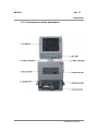

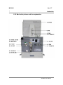


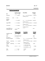
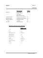
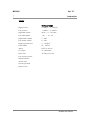
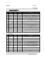
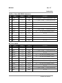


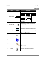


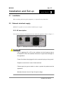
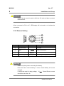


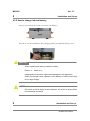
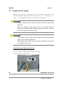

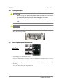

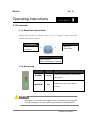

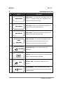

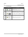
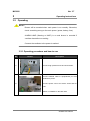
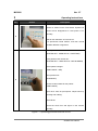
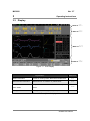
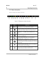

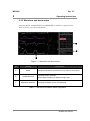

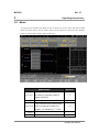
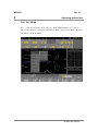


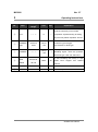
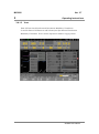

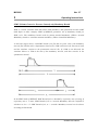


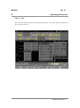

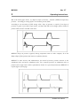
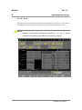
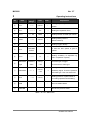

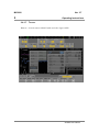
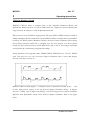

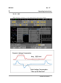

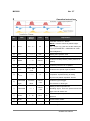

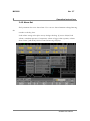
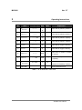

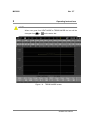

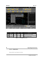


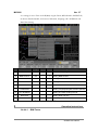
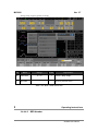

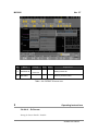
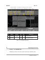
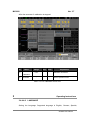

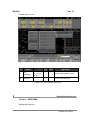

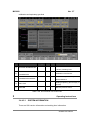
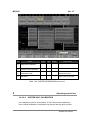
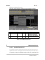
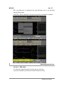
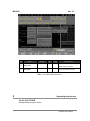


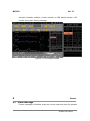
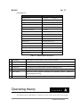


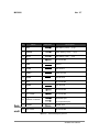

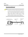


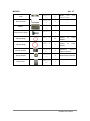
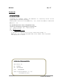


![User`s Manual MV2000[SU:M] Ventilator System 0470](http://vs1.manualzilla.com/store/data/005841388_1-c867b5a0773523e6306e353a41d4c56d-150x150.png)