1
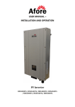
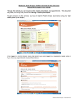
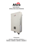
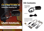
User’s Manual of Web monitor HMI-901
Version:UM02EN-140306
AforeUK Ltd | Unit 6 The Maltsters | Wetmore Road | Burton on Trent | Staffordshire | DE14 1LS
www.aforeuk.com | [email protected] | 01283 845039
1. Installation
Web monitorHMI-901 should be installed at least 20cm away from the inverter, or the signal will
decrease. Screw the monitor back or stick with adhesive.
2. Wiring
2.1 Start wiring
1) Disconnect the inverter from both AC and DC supplies
2) Loosen the screws and Open the waterproof cover
(picture 2-1 and 2-2)
2-1
2-2
3) Put the communication wire through the waterproof connector.( picture 2-4)
4) Connect the wires one by one according to the wire colors and the definition chart, and
ensure that all terminals are tight and sound. ( picture 2-4)
*Definition of different wire (picture2-3):
Colour
Red
Yellow White Black
Definition +5V
485A 485B GND
2-3
5) Plug in the Green communication socket back into the inverter. (picture 2-5)
1 /8
Version:
2-4
2-5
6) Close the waterproof cover, tighten the screws and the waterproof connector.(Picture 2-6)
2 /8
Version:
2-6
Notice: Please do not mistakenly connect the red and black wire in the
communication port, otherwise the monitoring module might be damaged.
3 Wireless portal configuration
3.1 Make sure the inverter is up and running and generating before
configuration.
3.2 Using a laptop, cell phone or tablet PC, open the WIFI/WLAN interface on
your device to search for the WIFI signal of the monitor, (your laptop or your
cell phone might be already connected with your existing home/office wifi
signal, please disconnect with it first if there is any), the WIFI signal name will
be like ”Afore_xxxxxx”, Picture 3-1)
3.3 Notice: No password is needed to connect to the Afore network.
3-1
3.4 Connect to the Afore_xxxxxx WIFI signal
3.5 Open up the internet browser on your device and locate the address bar
3.6 In the address bar, type 11.11.11.1 and press enter. This will bring up a new
AforeUK Ltd | Unit 6 The Maltsters | Wetmore Road | Burton on Trent | Staffordshire | DE14 1LS
www.aforeuk.com | [email protected] | 01283 845039
interface (Picture3-2),
3.7 Both the user’s name and password are “admin”
3-2
3.4 Click “confirm/OK ” and move into next interface, copy and paste the Serial
number “65……c8” and save it in a file or write down in the box below, this number
will be useful when registering the monitor the Afore website later. (Picture 3-3)
Note: This SN number here is the web monitor’s serial number, has nothing
to do with the inverter SN number.
3-3
3.5 Click Find AP,
3.6 Open the Scan interface, and it will automatically search for all wireless
routers in the surrounding area.
3.7 Select your home or office Network and connect.
3.8 In the next interface (Picture 3-3), input the password to your existing router
in the Key column (Picture 3-3). Please make sure the signal strength is at
least 30% (Picture 3-4), otherwise the communication will affected.
3-4
3.9 Click “Save and reboot “to save this configuration。
3.10 Wait for 5 seconds to complete the process.
3.11 Either press refresh or ‘F5’ to reload the page.
3.12 Move onto the account register section.
Picture3-5
3.13 If Current Local IP; Current Netmask; Current Gateway IP; Current DNS
Server all displays specific data rather than “0”, it means the monitor device
has successfully obtained an IP address and can work normally.
3.14 If the interface shows as Picture 3-6, it means the monitor device failed
to connect with the router or the internet connection is not normal. When
this happens, user should check if the password of the router is correct or if
the wifi signal is too weak.
Picture 3-6
It is also possible that the user’s router has got a Static ip address,
The user can use the similar method to set up by clicking “IP Address”, enter the IP
address setting interface. Close DHCP Select by choosing Disable, then input the
Static IP address, net mask, gateway ip and DNS. Then Save the settings.
Wait for 2 minutes and retype 11.11.11.1 in the web browser and enter, then click IP
Address and check. If Current Local IP; Current Netmask; Current Gateway IP; Current
DNS Server all displays specific data rather than “0”, means the setting is successful.
If not, please confirm if the router allows wireless device to be connected. (This
check function haven’t been implemented for the current stock before 23rd April.
If the router needs MAC address, please get it from the previous copying SN step.
4 Account register
4.1 Using your laptop or PC, disconnect from “Afore_xxxx” wifi and connect onto
your home/office wifi network.
4.2 Visit http://www.aforenergy.com/ website and Click “Register” button on the
Monitoring System User Login.
4.3 This will bring up the “Afore Energy Remote Monitoring” log in
interface(Picture 4-1),
4.4 Select your desired language in the bottom right corner, click “Sign up”
4.5 Then interface like Picture 4-2 shows. Input user’s name, password, register
email address and the SN number which had been saved in Chapter 3.3, click
sign up to confirm and complete the registration.
4-1
4-2
4.6 After registration is completed,
4.7 Login with YOUR user name and password, select your own language in the
upper right corner if necessary. This setting will be saved to this account
number, when you log in next time, you wont need to set this up again.
5 User’s instructions
5.1 Log in
Log into the monitoring system with your registered user’s name and
password, the system will automatically generate a PV system monitoring
site, called “my sites” (Picture 5-1)
5-1
Click “view”, to view the PV system’s operational data which will now be
displayed. (Picture 5-2)
5-2
5.2 Edit, add sites and add inverters by users
In Afore Energy Remote Monitoring System, users not only can view their
own sites, but can also edit.
Click “Edit”, move to the interface shown as Picture5-3, users could edit
content such as PV system name, location, local feed-in tariff, PV system
introduction, and can also select PV system location on the map.
5-3
The “Sort No” in the bottom shows the current PV systems position
sequence, the smaller number rank higher position of the list. Input the
relevant information and save the settings to complete the PV system new
site adding.
If users need to monitor more than one PV system, click “+New site” the
similar interface of editing site shows, also type in name, location
information etc. The only difference is users need to input the SN number of
the inverter installed in this PV system (Picture 5-4)
5-4
If users need to add more than one inverter in the monitoring system, click
“Inverters” in the left column, interface shown as Picture 5-5. Users could
edit current inverter or add new inverters with similar steps. Here we will
introduce “Add New Inverter” as an example
5-5
Click “Add New Inverter”, type in relevant information and click “save to”
complete the adding. (Picture 5-6)
5-6
5.3 User’s information setting
For Users to edit their own account information, click “Settings” in the left
column (Picture 5-7)。
5-7
5.4 PV system management
Afore Energy Remote Monitoring System provides abundant functions of PV
system monitoring and management.
5.4.1 Real-time Display
Real-time display provides users with basic real-time working data
information of the PV system, and enable the users to quickly view their
own PV systems working status. Select a site, click “view”, and choose
“Real-time display”(Picture 5-8)
5-8
5.4.2 Alarm Record
In the Alarm Record page, users could check the relevant event list for
each individual inverter, with additional info regarding fault codes and
the time that the fault occurred. (Picture 5-9)
5-9
5.4.3 History Record
In History Record page, users could check the curves of historical data
and could also check the specified time period of certain operation
parameters, such as “Power now” (Picture 5-10)
5-10
5.4.4 Report Analysis
In the Report Analysis page, users could check the PV system daily,
monthly, and yearly report.
5-11
5.4.5 Auto-sending Settings
In this page, users could set faulty report automatic sending by day, week
and month. See Picture 5-12, select the “on” option of the specific report.
Please use [email protected] for the alarm notification
only…….
then Save the settings, this will allow any faults that occur to be monitored
and resolved by Afore.
5-1