1
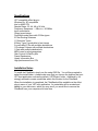
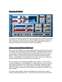
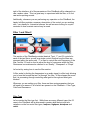
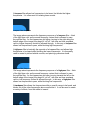
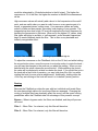
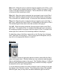
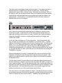
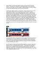
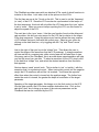
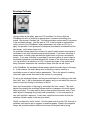
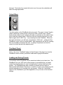
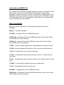
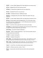
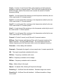
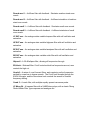
Tone2 FilterBank – User’s Manual
V2.5
Revision 1.5 – February, 2007
Copyright 2006 Tone2
Manual written by Michael McGrath
Tone2 is proud to present FilterBank 2, a high-quality stereo filter module for VST
compatible host applications. Picking up where our wildly popular freeware
FilterBank left off, we have added tons of powerful features, and a stunning new
user interface. Featuring two multi-mode filters, multiple distortion types, dual
LFOs, an envelope follower, programmable gate and a powerful delay module,
the FilterBank 2 drastically extends the ‘filter plug-in’ concept to provide today’s
creative musicians with an extremely powerful multi-effect tool.
We have worked hard to create the ultimate filter module for today’s musicians,
and are certain that you will find it to be a useful and powerful tool in your musical
arsenal. We hope you have a lot of fun making music with the FilterBank!
Please visit our webpage at www.tone2.com for the latest news and updates for
all of our products.
Specifications
VST compatible effect plug-in
Windows 9x, XP compatible
Intel or AMD CPU
Sample Rates: 22, 44, 48 or 96 kHz
Frequency Response: < 20hz to > 20,000hz
Input mono/stereo
Output mono/stereo
Dual Multi-mode filters with 53 filter types
6 Filter Routing Schemes
11 Distortion Types
8 Delay Types, synch-able to host tempo
2 synch-able LFOs with multiple destinations
1 Envelope Follower with multiple destinations
1 Gate with multiple destinations
MIDI-Learn for most parameters
Gain Control & Wet/Dry Mix
Preset Randomizer
Handy Information Box
High performance/Low CPU
Installation Notes
To install the FilterBank, simply run the setup EXE file. You will be prompted to
select the install folder – please make sure that you choose the location that your
VST host application uses as the default ‘VSTPlugins’ folder. Additionally, it is
strongly advised to create a subfolder within this location for the FilterBank.
When the installation is completed, the FilterBank will be available on the effect
plug-in menu of your VST host application. An uninstaller will be created and
added to your start menu, which you may use if you would like to remove the
FilterBank from your computer at a later time.
Using the FilterBank
This section of the user’s manual will take an in-depth look at how all the controls
and functions on the FilterBank work. We will begin by examining the options for
Filter 1 and Filter 2 (found on the ‘Filter Panel’ at the upper left of the plug-in),
and then proceed with an in-depth look at the other modules.
A Note on Control Options and Midi Learn
All knobs on the FilterBank have been programmed for control by circular mouse
movements (with the left mouse button held-down). Additionally, these controls
may all be reset to their default position by holding down the <CTRL> button on
your computer’s keyboard, and then left-clicking on the knob with your mouse
pointer. Finally, if you would like to have a finer resolution when turning the
knob, you may achieve this by holding down the <ALT> key on your computer’s
keyboard while rotating the knob with your mouse pointer.
All knob controls on the FilterBank are MIDI-Learn enabled. To bind a control
from the FilterBank to an incoming MIDI CC, simply right-click on the control you
wish to bind, so that you see the “MIDI Learn” label appear, and then send the
appropriate MIDI CC from your control surface (usually by simply turning the
knob). The selected control on the FilterBank will be mapped to the MIDI CC you
have selected.
One other ‘hidden feature’ inside the FilterBank is the ‘cheat mode’, which is
actually a patch/preset randomizer. If you click on the silver screw at the bottom
right of the interface, all of the parameters of the FilterBank will be changed to a
new, random value. This is a great way to experiment with the filter, or to find
new and surprising sounds.
Additionally, whenever you are performing any operation on the FilterBank, the
handy Info Box provides a summary description of the control you are working
with – very handy for ‘interactive learners’ as well as users looking for a quick
reminder on how a certain control may be used.
Filter 1 and Filter 2
This section of the FilterBank provides identical ‘Type’, ‘F’ and ‘Q’ controls for
each of the two filters, as well as a single control to adjust how the filters are
arranged within the audio path. ‘F’ is used to control the cutoff frequency of the
filter, and the ‘Q’ knob is used to adjust the level of resonance within the filter.
Resonance is sometimes also referred to as “Quality”, “Steepness” or “Slope”.
Let’s start by seeing how to use the filter section.
A filter works by limiting the frequencies in an audio signal; in effect only allowing
you to hear the sounds that are “let through” the filter. A filter shapes the sound
that it is processing through controlling what gets let through and what gets
blocked.
Whenever you are setting up a filter, there are three main parameters that you
will need to be aware of, all of which are present on the FilterBank – Filter Type,
Cutoff and Resonance.
Filter Type
Let’s consider the filter type first. While there are many different types (the 53
ones in the FilterBank will be discussed in greater detail below) most are
variations on the four main filter types, lowpass, highpass, bandpass and
notch.
A lowpass filter allows low frequencies to be heard, but blocks the higher
frequencies. It is often used for isolating bass sounds.
Lowpass Filter Response
The image above represents the frequency response of a lowpass filter – think
of the light blue color as the sound frequency content that is allowed to pass
through the filter. As the frequencies get higher (moving to the right along the
bottom edge of the image) they begin to ‘roll off’, with less and less emphasis
until no higher frequency content is allowed through. In this way, a lowpass filter
allows low frequencies to pass, while blocking high frequencies.
A highpass filter is basically the opposite of a lowpass filter, and allows high
frequencies to be heard while blocking the lower frequencies. It is frequently
used to create hi-pitched whistle sounds, and piercing synthesizer leads.
Highpass Filter Response
The image above represents the frequency response of a highpass filter – think
of the light blue color as the sound frequency content that is allowed to pass
through the filter. As the frequencies get lower (moving towards the left on the
bottom edge of the image) they begin to ‘roll off’, with less and less emphasis
until no low frequency content is allowed through. In this way, a highpass filter
allows low frequencies to pass, while blocking low frequencies.
A bandpass filter allows the frequencies within a specific range to be heard, and
blocks out all the other frequencies above and below it. It can be used to create
a variety of effects, from the subtle to insane!
Bandpass Filter Response
The image above represents the frequency response of a bandpass filter – think
of the light blue color as the sound frequency content that is allowed to pass
through the filter. As the frequencies move away (in both directions) from the
center frequency they begin to ‘roll off’, with less and less emphasis until no
lower or higher frequency content is allowed through. In this way, a bandpass
filter allows a set ‘band’ of frequencies to pass, while blocking all others.
A notch filter is the opposite of a bandpass filter – it will block the frequencies
within a set range, and allow all other frequencies above and below it to be
heard. Like the bandpass filter, it can be used to achieve a wide variety of
effects.
Notch Filter Response
The image above represents the frequency response of a notch filter – think of
the light blue color as the sound frequency content that is allowed to pass
through the filter – and note that this time the filter’s shape blocks frequencies
from passing instead of allowing them. As the frequencies move away (in both
directions) from the center frequency, the sound begins to ‘roll back in’ - with
more and more emphasis until all lower and higher frequency content is allowed
through. In this way, a notch filter blocks a set ‘band’ of frequencies, while
allowing all others to pass.
To select a filter type on the FilterBank, click on the ‘Type’ box for either Filter 1
or Filter 2, and select the desired filter type from the menu. The 53 variations on
the standard filter types will be described in further detail at the end of this
manual.
Cutoff – ‘f’
Now that we understand how the different types of filters function, we can look at
the Cutoff function. Cutoff is used to set the frequency at which the filter’s
behavior changes, relative to the filter type. In a lowpass filter, the cutoff will set
the frequency at which the filter begins to ‘close’ and allow less and less of the
higher frequencies through. When the frequencies are high enough past the
cutoff point, no more sound will be allowed through the filter. When the cutoff
point is set fully closed (full counter-clockwise), no sound will be allowed through
the filter.
In a highpass filter, the opposite applies – the cutoff sets the frequency point at
which the filter begins to reject sounds that are lower than the cutoff point.
Sounds far enough below the cutoff point will not be let through the filter at all.
When the cutoff point is set fully open (full clockwise), all frequencies will be
allowed through the filter.
In a bandpass or notch filter, the cutoff value acts a little but differently – it sets
the center point of the ‘band’ or ‘notch’, which will taper off as the frequencies
move away from the cutoff point, both in higher or lower frequencies.
To adjust the cutoff on the FilterBank, click on the ‘f’ dial, and while holding the
mouse button down, move the mouse in a circular motion to rotate the knob –
you will hear the changes to the audio as you adjust the setting. When you are
satisfied with the value, release the mouse button. While adjusting the control,
the cutoff value will be displayed in a label box below the knob. If you would like
to turn the knob with a finer level of precision, you may hold down the <Alt> key
while rotating the knob for more precise adjustments. Additionally, holding down
the <Ctrl> key and clicking on the knob will reset it to its default (center) position.
Please note that while these descriptions are generic across most filter types, the
FilterBank includes some ‘special’ filter types that use the Cutoff and Resonance
functions in different ways. Please refer to the section below on Filter Type
Details for more information on how these controls may differ for certain filter
types.
Resonance – ‘Q’
Understanding how the cutoff function works is essential to understanding
resonance. In essence, resonance controls the steepness of the ‘slope’ around
the cutoff point. A very steep slope would filter more frequencies sooner, relative
to the sound moving away from the cutoff point. In comparison, a very soft slope
would have the filtering applied more subtly, and require a farther frequency from
the cutoff point to achieve complete signal attenuation.
Bandpass Filter with low ‘Q’
Bandpass Filter with high ‘Q’
Steep filter response slopes are referred to as having a higher resonance value,
or sometimes a higher ‘Q’ (which refers to ‘quality’ – a steeper curve is a higher
quality filter because it is more precise).
The slope of a filter’s response curve is often measured in dB/Oct, or ‘Decibels
per Octave’. Values may look like 18dB/Oct, 30dB/Oct, etc. Using 18dB/Oct as
an example, this means that a frequency an octave away from the cutoff point
would be attenuated by 18 decibels relative to the full signal. The higher the
resonance or ‘Q’ of the filter, the higher the number in the dB/Oct measurement
will be.
High resonance values will actually add a boost to the frequencies at the cutoff
point, and are useful when you want to really focus on a very precise part of a
sound, or generate intense, cutting tones. Low resonance values are better
suited to subtle and less precise ‘smoothing’ and shaping of your sounds. The
images below show how a high ‘Q’ level can emphasize the cutoff frequency by
boosting the frequencies in that area. When set to the highest ‘Q’ values, many
filter types will begin to oscillate, or ‘self-resonate’, as the boosted frequencies
begin to create feedback inside the filter. This is often a very desirable and
instantly recognizable effect.
Lowpass Filter with low ‘Q’
Boosting frequencies with high ‘Q’
To adjust the resonance on the FilterBank, click on the ‘Q’ dial, and while holding
the mouse button down, move the mouse in a circular motion to rotate the knob –
you will hear the changes to the audio as you adjust the setting. When you are
satisfied with the value, release the mouse button. While adjusting the control,
the value will be displayed in a label box below the knob. If you would like to turn
the knob with a finer level of precision, you may hold down the <Alt> key while
rotating the knob for more precise adjustments. Additionally, holding down the
<Ctrl> key and clicking on the knob will reset it to its default (center) position.
Routing
Because the FilterBank provides the user with two individual multi-mode filters,
the user has multiple options for how these filters are arranged. Changing the
routing of multiple filters can drastically affect the sound, and the seven routing
possibilities within the FilterBank take full advantage of this powerful concept.
Bypass – When in bypass mode, the filters are disabled, and they will process
no sound.
Filter 1 – When Filter 1 is selected, only this filter will be active.
Filter 2 – When Filter 2 is selected, only this filter will be active.
Filter 1->2 – When this option is selected, the input signal is sent to Filter 1, and
Filter 1’s output will be routed to the input of Filter 2. Finally, the output of Filter 2
is sent to the other modules of the plug-in. This is referred to as ‘serial routing’,
or having two filters operating in series.
Filter 1+2 – When this option is selected, the input signal is sent to both Filter 1
and Filter 2, and their outputs are both sent to the other modules of the plug-in.
This is referred to as “parallel routing”, or having two filters operating in parallel.
Filter 1–2 - When this option is selected, the input signal is sent to both Filter 1
and Filter 2, and then the output of filter 2 is subtracted from the output of Filter 1.
The resultant signal is then sent to the other modules of the plug-in.
1=L 2=R – When this option is selected, the input signal is sent to both Filter 1
and Filter 2. The output of Filter 1 is routed to the stereo left circuit, and sent to
the remaining modules in the plug-in, while the output of Filter 2 is routed to the
stereo right circuit, and sent to the remaining modules in the plug-in.
To adjust the routing of the filters, simply click on the ‘Routing’ box in between
Filter 1 and Filter 2 on the plug-in. A list of routing options will appear, and you
may click on the appropriate selection to select it.
Distortion
The FilterBank includes a high quality distortion module, placed after the filter’s
output in the signal chain. Distortion effects are very commonly used alongside
filters to add beefiness or edge to the sound. The FilterBank features 11 different
distortion types (described in more detail below), as well as the ability to bypass
the distortion unit for ‘pure’ filtering effects.
To use the distortion module, first select a distortion type by clicking on the dark
blue display in the ‘Distortion’ section. This will bring up a menu of all available
distortion types, and you may select the desired distortion type from the list.
The Drive knob is used to adjust the amount of signal that is being fed into the
distortion module. The higher the value, the greater the effect of the distortion
effect will be, from subtle to very overdriven and extreme sounds.
To adjust the drive, click on the Drive dial, and while holding the mouse button
down, move the mouse in a circular motion to rotate the knob – you will hear the
changes to the audio as you adjust the setting. When you are satisfied with the
value, release the mouse button. If you would like to turn the knob with a finer
level of precision, you may hold down the <Alt> key while rotating the knob for
more precise adjustments. Additionally, holding down the <Ctrl> key and clicking
on the knob will reset it to its default (center) position.
Delay
The FilterBank also includes a simple but powerful delay module, useful for
adding motion, depth and color to your sounds. In combination with the
processing from the filters and gate module, creative use of the delay can result
in some very interesting, powerful and rhythmic sounds. The delay effect can be
placed before the filters, or after them, and thus each delay type has two entries
in the list. A delay type with the ‘>’ character before the delay’s name (example:
“>Simple”) will be routed to the input of the filters. A delay type with the ‘>’
character after the delay’s name (example: “Simple>”) will appear after the filter’s
output.
Select a filter type by clicking on the dark blue “type” box. You will see many
types of delays, from simple echoes, to spatial and panning effects. Next, select
the sync options. This allows you to synchronize the ‘beats’ that the delay’s
echoes fall on, relative to the tempo (in BPM, beats per minute) and song
position of your host sequencer.
Synchronizing delay times to the tempo of your project results in very rhythmic
delay sounds that are “in time” with your song. Select the division of the host
tempo that you want to use for delay synchronization by clicking on the dark blue
“sync” box, and selecting an option from the menu that appears. Additionally,
you may navigate through the available sync options by pressing on the up or
down arrow buttons.
The final control in the delay module is the send knob. This allows the user to
adjust the amount of signal that is fed into the delay unit. Another way to
describe this control is as a “wet/dry” knob. When set fully clockwise, 100% of
the signal is sent into the delay module. When set at the mid-point, the resultant
sound will be a half-and-half blend of the original signal, and the output of the
delay module. In this manner, it is possible to blend in the exact amount of
desired delay into your final signal.
Gate
One of the most powerful and interesting types of effects to use with a filter
processor is a gate. A gate acts like a door, letting sound through when it is
open, and blocking he sound when it is shut. Creative use of gate processing
allows the thoughtful musician to create rhythmical pulsing, throbbing, and
‘strobe’ like sounds.
On the left side of the gate is a 16-step sequencer. A block represents each
step, and they are grouped into four segments of four blocks each – a perfect
relation to the division of quarter notes in a bar of common time. A block may be
either ‘on’ or ‘off’, and simply clicking on each block toggles this state. When a
block is off, it will be a dark color, and the sound from the FilterBank will be
muted when the sequencer is on this step. Obviously when all blocks are turned
on, the gate will have no effect, as sound will never be blocked from leaving the
FilterBank by the gate.
When the sequencer is running, a ‘chase light’ will move across the top of the
sequencer, showing the user the step that is currently being processed. This
makes it very easy to select a specific step to either mute or enable to achieve
the desired sound.
Like the delay module, the gate effect is most interesting when synchronized to
the host sequencer’s tempo (in fact this is the only way it will work!), so there is a
‘sync’ option available. Click on the dark blue ‘sync’ box to select the multiple (or
division) of the host sequencer’s tempo, and this will be used for the tempo of the
gate’s sequencer. Like with the delay module, you may also toggle from one
setting to another by use of the up and down arrow buttons.
The next control on the gate processor is ‘shape’. This allows the user to control
the envelope response curve that the gate will use when shutting (to block sound
output) or opening (to allow sound output). “Sharpest” will cause the gate to
open and shut as quickly as possible, instantly muting any sound that was
playing. This may be too dramatic for some applications, so other response
curves such as “Softer” are also available. Experimentation is the key to finding
the type of envelope that best suits the sound you are after.
Following the ‘shape’ control is a ‘send’ knob. Similar to the send knob on the
delay module, this allows the user to blend in the exact amount of gate
processing they desire – from a subtle “barely there” effect, to 100% fully wet.
Finally, there is one last parameter that needs to be examined before we can
properly set up any gate processing. The ‘dest’ option allows the user to select a
parameter of the FilterBank’s functions to be processed by the gate. Most gate
effects are found hard-wired to ‘volume’, so that they act as dedicated gates to
the output of the plug-in they reside on. While the FilterBank does allow the gate
to be routed to volume, a wealth of other options are available, such as filter
cutoff, filter frequency, panning, distortion drive, etc. Again, experimentation is
the key, and the adventurous musician will find an enormous amount of flexibility
and inspiring sounds from exploring the different possibilities afforded by the gate
module.
LFOs
As we have seen above, the gate can be used to create interesting textures and
rhythmic effects for various parameters of the FilterBank – but it’s not the only
way! We have also included two powerful LFOs (Low Frequency Oscillators),
which, like the gate, have flexible destinations, and can be used to dramatically
(or subtly!) spice up your sound.
An LFO works by creating a rising and falling waveform, moving at a sub-audio
(less than 20hz, or ‘cycles per second’) rates. This waveform can typically be
linked to any of multiple different parameters, giving the effect of having the
parameter ‘rise’ and ‘fall’ according to the waveform and rate of the LFO. It’s a
simple yet powerful way to automate control over various parameters, and create
a more interesting, dynamic sound.
The FilterBank provides users with two identical LFOs, each of which functions in
isolation to the other. Let’s take a look at the options on the LFOs.
The first item we see is the ‘f’ knob on the left. This is used to set the ‘frequency’
(or ‘rate’) of the LFO. Since the LFO can also be synchronized to the tempo of
the host sequencer, this knob will only affect the LFO rate when the ‘sync’ option
is set to ‘none’. When you are not tempo-synching the LFO, use this control to
adjust the speed of the LFO.
The next item is the ‘sync’ menu. Like the sync function found on the delay and
gate modules, this lets you set a tempo for the LFO that is relative to the tempo
of the host sequencer. Using this tempo-sync function allows the easy creation
of LFO effects that are in time with the current song. Select a sync option by
clicking on the dark blue box, or by toggling with the “Up” and “Down” arrow
buttons.
Just to the right of the sync box is the “shape” box. This allows the user to
control the shape of the waveform that the LFO produces. A triangle waveform
will rise and fall at a constant rate, while a rising saw will fall faster than it rises.
Like many parts of the FilterBank, this is an area where experimentation will help
you find the sound you are after. To select a waveform for the LFO, simply click
in the dark blue “shape” box, and select the desired waveform from the menu
that appears.
Next we have a ‘send’ control knob. This is similar to ‘mix’ or ‘wet/dry’, with the
exception that it is a polarized control. When turning this control into the negative
range, the LFO waveform will act like it is inverted – it will have the opposite
effect from when the control is turned into the positive range. The further from
center the control is turned, the greater the depth of modulation of the target
parameter.
Speaking of the target parameter, this brings us to the final control on the LFO.
Like the gate module, the LFOs have modular destination slots. Click on the
dark blue “dest” box to bring up a menu of the various parameters on the
FilterBank that can be controlled by the LFO.
Envelope Follower
Having looked at the delay, gate and LFO modules, it’s obvious that the
FilterBank has a lot of tricks up its sleeve when it comes to animating your
sound. But we aren’t finished yet! The final modulation unit we want to introduce
is the envelope follower. Like the gate or LFO, it can be used to automate the
motion of one of the FilterBank’s many parameters, but unlike an LFO (or a
gate), its operation is not governed by temporal (time-based) considerations like
host tempo. Let’s take a closer look.
An envelope follower tracks the volume of a specific audio signal, and outputs a
modulation curve that follows the signal being tracked. If you were ‘following’ a
square wave, it would output an identical square wave to use as a modulation
source. If you were ‘following’ a recording of someone yelling, it would output a
modulation signal that rises and falls with the volume of the voice that is yelling.
You can think of it as similar to an LFO, however the shape of the audio signal
being ‘followed’ determines the ‘waveform shape’ that the unit will output.
In the FilterBank, the envelope follower always tracks the audio input to the plugin. In this manner, the audio being sent to the plug-in can be used as a
modulation source to control various parameters. This is the secret to creating
‘auto-wah’ type sounds that react to the volume of your playing.
To set up the envelope follower, first choose a destination by clicking on the dark
blue “dest” box. A list of destinations will appear, and you can select the one you
want to control by clicking on the entry in the list.
Next, send some audio to the plug-in, and adjust the ‘time’ control. This knob
adjusts how quickly the envelope follower reacts to changes in the audio signal
being monitored. You may want to have a slow and lazy response, even if your
audio signal is changing very quickly and dynamically – or you may require a
very fast ‘real-time’ response. In any case, adjust the time control so that the
envelope follower reacts in the way you desire.
Finally, we have the “send” control. Like the send control on the LFO, this one is
polarized, and may be set to negative or positive ranges. When in the negative
range, the actual modulation will be the inverse of the signal that is being
followed. The further from center this knob is set, the more the modulation will
affect the target parameter.
Output Mixer
The final module on the FilterBank is the mix panel. The upper “volume” knob is
used to adjust the overall volume of the plug-in itself, and the lower “dry/wet”
knob acts as a blend control, allowing the user to creatively mix the output of the
plug-in with the original signal. When set fully left (counter-clockwise), you will
hear a signal that is 100% ‘dry’ – no processing from the FilterBank. When set
fully right (clockwise), you will hear a signal that is 100% ‘wet’ – nothing but the
FilterBank’s output, and no original signal. Most applications will call for a setting
that is somewhere in between the two – as always, experiment and set this
control to a level that suits the desired result.
The About Panel
Click on the silver ‘FilterBank’ badge on the left edge of the plug-in to view the
FilterBank version number, production credits and copyright information.
Loading and Saving Presets
Your settings on the FilterBank may be saved and called up at a later time. The
FilterBank uses your VST host’s preset system to accomplish this, so please
consult the documentation for your host application for more details on using
presets. The FilterBank ships with a number of presets that are useful to
demonstrate the flexibility of the plug-in, as well as to serve as a starting point for
musical inspiration or for creating your own presets. Select the “load preset”
option for the FilterBank in your host application to try out some of the included
settings.
Automation and MIDI CC’s
The controls on the FilterBank may be automated to allow for full control over the
plug-in within your project. The FilterBank will respond to standard VST
automation, as well as to MIDI CC control. Information on mapping MIDI CC’s to
FilterBank controls is presented at the start of this manual. For details on using
VST automation within your host application, please refer to the documentation
that accompanies your host software.
Filter Type Details
Below you will find a description of the different filter types found in the
FilterBank:
Bypass – The filter is disabled.
LP 30dB – A lowpass filter with a 30dB/Octave slope.
LP Moog 24 – A lowpass filter with a 24dB/Octave slope, with a classic ‘Moog
Diode Ladder Filter’ type response.
LP Moog 6 – A lowpass filter with a 6dB/Octave slope, with a classic ‘Moog
Diode Ladder Filter’ type response.
LP SVF – A ‘state variable’ lowpass filter, slope adjusted by resonance control.
LP Silk - Resonant lowpass filter with shiny, silky resonant treble frequencies.
LP Fat - A lowpass filter with very broad resonance.
LP Fat 7 - A lowpass filter with double resonance tuned a 7th interval from the
cutoff point.
LP Oct – A lowpass filter with resonance tuned in octave distance from the cutoff
point.
LP Ellipt - A ‘brickwall like’ lowpass filter with very steep slope.
LP Like - A lowpass filter with a very soft slope.
HP 30dB – A highpass filter with a 30dB/Octave slope.
HP Moog 24 – A highpass filter with a 24dB/Octave slope, with a classic ‘Moog
Diode Ladder Filter’ type response.
HP SVF – A ‘state variable’ highpass filter, slope adjusted by resonance control.
HP Fat - A highpass filter with very broad resonance.
HP Ellipt - A ‘brickwall like’ highpass filter with very steep slope.
HP Like - A highpass filter with a very soft slope.
BP 15dB – A bandpass filter with a 15dB/Octave slope.
BP Moog – A bandpass filter with a classic ‘Moog Diode Ladder Filter’ type
response.
BP SVF – A ‘state variable’ bandpass filter, slope adjusted by resonance control.
BP Para - Double parallel-switched bandpass filters. The Cutoff knob controls
the center frequency of bandpass filter 1, and the Resonance knob controls the
center frequency of bandpass filter 2.
Notch – A notch filter with an adjustable center frequency and slope.
Notc Moog - A notch filter with an adjustable center frequency and slope utilizing
a a classic ‘Moog Diode Ladder Filter’ type response.
NoLP Moog – A notch filter lowpass combination.
Equalizer – A filter for program equalization. The Cutoff knob boosts bass and
the Resonance knob boosts treble.
Lo Shelf – A lowpass shelving filter.
Hi Shelf – A highpass shelving filter.
PEQ + Wide – An equalizing filter with a broad slope. The Cutoff knob controls
the center frequency and the Resonance knob controls the amount of boost.
PEQ + Tight - An equalizing filter with a tight slope. The Cutoff knob controls the
center frequency and the Resonance knob controls the amount of boost.
Comb 1 – A comb filter, with multiple equally spaced resonance peaks.
Comb 2 – A different comb filter, similar to Comb 1.
Phaser - A phasing filter that affects the phase offset of the incoming audio
stream.
Vocals – A series of vocal formant filters, each centering on the frequencies
emitted by vowel use in human speech. The Cutoff knob morphs through the
IEAOU formants, and the Resonance knob controls the amount of formant
frequency shifting.
Vocal A - A vocal formant filter centering on the frequencies emitted by the use
of the vowel sound ‘A’ in human speech.
Vocal U - A vocal formant filter centering on the frequencies emitted by the use
of the vowel sound ‘U’ in human speech.
Vocal E - A vocal formant filter centering on the frequencies emitted by the use
of the vowel sound ‘E’ in human speech.
Vocal I - A vocal formant filter centering on the frequencies emitted by the use of
the vowel sound ‘I’ in human speech.
Vocal O - A vocal formant filter centering on the frequencies emitted by the use
of the vowel sound ‘O’ in human speech.
Formant 2 - Double Formant (vocal) filter with 2 resonant maxima.
M-Shape - Serial lowpass and highpass filters, with 2 resonant maxima at the
edges of the filter - cuts both treble and bass. The Cutoff knob contols the
lowpass frequency and the Resonance knob controls the highpass frequency.
Resonator – A short delay with feedback.
Resample – Resamples the signal to a lower sample rate. It creates spectral dirt.
AM - The signal is amplitude modulated with a sine.
FM Sine – Frequency modulation with a sine.
FM Tri – Frequency modulation with a triangle.
FM Saw – Frequency modulation with a sawtooth.
Delay – Adds a delay to the signal.
Allpass – An allpass filter, allowing all frequencies through.
Reverb big 1 – A diffuser filter with feedback. Simulates large room reverb.
Reverb big 2 – A diffuser filter with feedback. A different simulation of large
room reverb.
Reverb med 1 – A diffuser filter with feedback. Simulates medium-sized room
reverb.
Reverb med 2 – A diffuser filter with feedback. A different simulation of mediumsized room reverb.
Reverb small 1 – A diffuser filter with feedback. Simulates small room reverb.
Reverb small 2 – A diffuser filter with feedback. A different simulates of small
room reverb.
LP SVF ana – An analogue state variable lowpass filter with self oscillation and
saturation.
HP SVF ana – An analogue state variable highpass filter with self oscillation and
saturation.
BP SVF ana – An analogue state variable bandpass filter with self oscillation and
saturation.
BR SVF ana – An analogue state variable notch filter with self oscillation and
saturation.
Allpass2 – A 30 dB allpass filter, allowing all frequencies through.
EQ block – Brickwall filter. Cutoff controls which low frequencies are cut, reso
controls the high cut.
Vocals2 – A series of vocal formant filters, each centering on the frequencies
emitted by vowel use in human speech. The Cutoff knob morphs through the
IEAOU formants, and the Resonance knob controls the amount of formant
frequency shifting.
Comb 5 – A comb filter, with multiple equally spaced resonance peaks.
LP Moog 24 – A lowpass filter with a 24dB/Octave slope, with a classic ‘Moog
Diode Ladder Filter’ type response and analogue dirt.
Distortion Type Details
Below you will find a description of the different distortion types found in the
FilterBank:
Bypass – When this mode is selected, the distortion module will be bypassed.
Tube Amp – A ‘soft knee’ saturated distortion.
Hard Clip – A ‘hard knee’ clipping distortion.
Presence – A ‘soft knee’ saturated distortion with falloff at higher levels.
Wavewrap – This distortion type adds additional harmonics by using edged
nonlinear amplification of the audio signal.
Waveshape – This distortion type adds additional harmonics by using round
nonlinear amplification of the audio signal.
Bitcrush – This distortion type reduces the bitrate of the audio to ‘lo-fi’.
Volume – Changes the volume of the signal without adding harmonics.
Square - This distortion type adds additional harmonics by multiplying the signal
with itself.
Cubic - This distortion type adds additional harmonics by multiplying the signal
with itself.
Compressor – A compressor effect. Drive controls the threshold. Use this one to
avoid feedback overloads if you route a delay to the input.
Warble - This distortion type adds additional harmonics by using round nonlinear
amplification of the audio signal.
Default Midi CC# mapping
0
1
7
14
15
16
17
18
19
20
21
22
23
24
25
26
27
28
29
30
31
71
74
85
86
87
88
89
90
91
92
93
94
95
102
103
104
105
106
107
108
109
110
111
112
113
114
115
116
117
118
119
120
Reso1
Cutoff1
Volume
Filtertype1
Cutoff1
Reso1
Filtertype2
Cutoff2
Reso2
Routing
Disttype
Drive
Volume
DryWet
LFO1f
LFO1sync
LFO1shape
LFO1send
LFO1dest
LFO2f
LFO2sync
Reso1
Cutoff1
LFO2shape
LFO2send
LFO2dest
Envtime
Envsend
Envdest
Delaysend
Delaytype
Delaysync
StepSync
StepShape
StepSend
StepDest
StepStep0
StepStep1
StepStep2
StepStep3
StepStep4
StepStep5
StepStep6
StepStep7
StepStep8
StepStep9
StepStep10
StepStep11
StepStep12
StepStep13
StepStep14
StepStep15
RandomButton