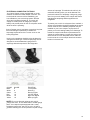
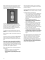
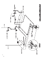
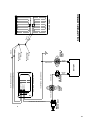
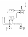
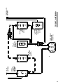
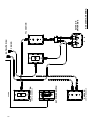
1
Lance Truck
Camper
Owner’s
Manual
WARNING
This User’s Manual contains safety information and
instructions for your camper.
You must read this manual before loading or towing
your camper.
You must follow all safety precautions and
instructions.
1
This page intentionally blank.
4
2
TABLE OF CONTENTS
LIMITED WARRANTY ................................................ 7
COVERAGE PROVIDED............................................... 7
OWNER’S OBLIGATION.............................................. 7
EXCLUSIONS............................................................... 7
IDENTIFICATION INFORMATION ............................ 8
A FEW IMPORTANT WORDS ON SAFETY . ............ 9
WELCOME ............................................................... 11
CUSTOMER RELATIONS INFORMATION . ........... 12
INFORMATION ABOUT THIS MANUAL . ............... 13
PRODUCT CHANGES............................................... 13
OWNER’S INFORMATION PACKAGE....................... 13
DEALER RESPONSIBILITY .................................... 14
PLANNING AND PREPARATION............................ 14
INSPECTION AND MAINTENANCE........................ 14
reporting safety defects . .......................... 14
camper and truck ............................................ 17
matching truck and camper........................... 17
tires......................................................................... 18
electrical connection to truck.................. 19
truck/camper load worksheet ................. 20
support equipment .......................................... 23
air bags................................................................... 23
heavy duty shocks............................................. 23
tiedowns and turnbuckles............................. 23
cabover truck struts...................................... 24
hitching and towing systems........................ 24
loading and unloading . ................................ 25
manual acme jacks............................................. 25
manual BALL screw jacks................................. 25
electric camper jacks...................................... 25
loading/removing camper............................... 28
loading camper on to truck.......................... 28
removing camper from truck........................ 28
leveling/stabilizing camper............................ 29
on the road ......................................................... 31
loading.................................................................... 31
storage.................................................................. 31
preparing for travel......................................... 31
pre-trip checks.................................................... 31
post-trip clean-up............................................... 31
safe driving rules.............................................. 31
riding in camper while traveling.................. 32
campground regulations............................... 32
carbon monoxide gas....................................... 32
effects of prolonged occupancy ........... 33
ventilation and moisture control ............. 33
dripping ceiling vents....................................... 34
interior odor....................................................... 34
fire and safety .................................................. 35
fire extinguisher................................................ 35
smoke detector.................................................. 35
carbon monoxide and propane
leak detector................................................... 36
equipment . ........................................................... 39
roof......................................................................... 39
compartment doors.......................................... 39
vents........................................................................ 40
roof vents............................................................. 40
fantastic roof vent........................................... 40
heki midi SKYLIGHT................................................. 41
cabover vent........................................................ 41
exterior lighting................................................ 41
roof rails and ladder....................................... 41
roof rack system............................................... 42
entry door............................................................ 42
windows.................................................................. 42
emergency exit window.................................... 42
saf-t-vue® window.............................................. 43
awnings................................................................... 43
slideout cover.................................................... 43
exterior wash station...................................... 43
camper bumper/step.......................................... 44
backup camera..................................................... 44
interior storage................................................. 44
bathroom............................................................... 44
toilet....................................................................... 45
cabover area........................................................ 45
galley...................................................................... 45
dinette cushions................................................ 45
dinette conversion............................................ 45
day/night shades................................................. 45
mini-blinds.............................................................. 45
folding divider door......................................... 46
fold-down bunk AND child restraint.......... 46
cargo net.............................................................. 46
fold-down tent................................................... 46
electrical systems ........................................ 49
12-volt dc system................................................ 49
battery and compartment............................... 49
battery terminology......................................... 49
battery information.......................................... 49
battery storage precautions....................... 50
battery charging................................................ 50
battery separator.............................................. 50
battery disconnect switch............................ 51
systems monitor panel..................................... 51
water heater ignition switch......................... 51
exterior light fuse box.................................... 51
CAMPER FUSE PANEL.............................................. 52
3
fuses........................................................................ 52
interior lighting................................................. 52
solar panel pre-wire......................................... 52
solar panel........................................................... 52
docking lights..................................................... 53
park/sat dish inlets............................................ 54
roof mounted HDTV antenna.......................... 54
tv ant/sat dish combo....................................... 54
satellite dish self-positioning...................... 54
lcd tv....................................................................... 54
exterior speakers.............................................. 54
120-volt ac system.............................................. 55
120-volt power cord.......................................... 55
120-volt generator power............................... 55
power distribution center............................. 56
ground fault circuit interrupter............... 56
generator ready................................................. 56
power generator............................................... 57
generator operating safety
precautions and warnings.......................... 57
generator maintenance and service.......... 58
generator/electrical component
incompatibility.................................................. 58
loading the generator.................................... 58
typical appliance loads................................... 58
power vs. altitude.............................................. 58
propane gas system ........................................ 59
btu’s......................................................................... 59
safety precautions............................................ 59
filling propane tank.......................................... 60
using propane system....................................... 60
single propane tankS........................................ 60
dual propane tanks............................................ 60
propane at low temperatureS....................... 61
combINATION carbon monoxide
AND propane leak detector........................ 61
exterior propane connection....................... 61
PROPANE GAS FUEL SYSTEM................................. 62
appliances ........................................................... 65
lighting propane appliances.......................... 65
refrigerator........................................................ 65
range-oven............................................................ 65
convection or microwave oven.................... 66
automatic ignition water heater
W/120V HEATING ELEMENT................................. 66
forced air furnace............................................ 66
roof mounted air conditioner...................... 67
combination furnace/air conditioner
thermostat........................................................ 67
fresh water system ........................................ 69
water pump............................................................ 69
water tank fill..................................................... 69
city water connection..................................... 70
water system drain............................................ 70
sanitizing fresh water system...................... 70
4
water filter........................................................... 71
shower.................................................................... 71
exterior wash station...................................... 71
waste system . .................................................... 73
insulated and heated waste holding
tank cover......................................................... 73
fresh water flush toilet................................. 73
black water holding tank............................... 73
dumping the holding tanks............................. 73
holding tank care/maintenance................... 74
black tank flush................................................. 74
slide-out room system (Rack and Pinion) ..... 75
system operation................................................ 75
normal operation............................................... 75
manual override operation............................ 76
electrical system maintenance.................... 76
mechanical maintenance................................. 76
system troubleshooting................................ 76
electrical troubleshooting......................... 76
slide-out room system (In Wall) ................... 77
system operation................................................ 77
normal operation............................................... 77
manual override operation............................ 77
electrical system maintenance.................... 78
mechanical maintenance................................. 78
system troubleshooting................................ 78
electrical troubleshooting......................... 78
general maintenance . ................................... 79
exterior maintenance....................................... 79
exterior graphics.............................................. 79
damage checks.................................................... 80
sealant renewal................................................. 80
doors and windows........................................... 80
acrylic windows/HEKI SKYLIGHT VENT............ 80
jack brackets....................................................... 81
camper jacks........................................................ 81
turnbuckles......................................................... 81
air conditioner.................................................... 81
overhead vents................................................... 81
skylightS................................................................ 81
exterior lights.................................................... 81
wiring...................................................................... 81
BATTERY(S)............................................................... 81
use AND care of the tent................................. 82
interior maintenance........................................ 82
interior odor....................................................... 82
upholstery and drapes.................................... 83
wall and ceiling panels.................................... 83
floors and carpetING....................................... 83
wood product care........................................... 83
FIBERGLASS TOP CARE........................................... 83
laminate top care............................................... 83
power range hood............................................. 83
refrigerator........................................................ 83
drains...................................................................... 83
shower care......................................................... 83
sink care................................................................. 83
maintenance chart 1.......................................... 85
maintenance chart 2.......................................... 86
winterization ..................................................... 87
operating in freezing conditions................ 87
storage.................................................................. 87
short-term storage........................................... 87
LONG-TERM STORAGE............................................ 87
storage below freezing.................................. 87
winterizing method............................................ 88
water heater bypass.......................................... 88
reactivatiNG camper after storage........... 88
outside area......................................................... 88
12-volt system...................................................... 89
120-volt system.................................................... 89
FRESH WATER SYSTEM........................................... 89
PROPANE SYSTEM................................................... 89
GENERAL................................................................... 89
maintenance.......................................................... 89
camper loading and checkout...................... 89
typical bulbs and fuses................................... 89
exterior sealant chart ................................ 90
schematics
typical fresh water system............................ 91
typical drain plumbing...................................... 92
typical propane system.................................... 93
running light wiring......................................... 94
docking light wiring......................................... 95
electrical jack wiring...................................... 96
monitor panel wiring........................................ 97
slide-out circuit wiring (RACK & PINION)...... 98
SLIDE-OUT CIRCUIT WIRING (IN WALL).................. 99
TYPICAL 12v system............................................ 100
TYPICAL 12v interior circuit wiring............. 101
STEREO speaker wiring.................................... 102
solar panel wiring........................................... 103
atwood thermostat wiring........................... 104
rvp coleman thermostat wiring................. 105
TYPICAL 120v system.......................................... 106
tv prewire............................................................ 107
tv antenna........................................................... 108
tv/sat antenna................................................... 109
sat dish antenna............................................... 110
suppliers service phone
and internet listing .................................. 113
5
This page intentionally blank.
4
6
LIMITED WARRANTY
FOR TRUCK CAMPERS MANUFACTURED BY LANCE CAMPER MANUFACTURING CORPORATION
(LANCE CAMPERS) SOLD IN THE UNITED STATES AND CANADA
Lance warrants to the original end user purchaser (“Owner”) of this truck camper (“Camper”) to be free of defects in
materials and workmanship and for structural integrity, under normal use, with reasonable care and maintenance, for
one (1) year from the date of purchase (the “Warranty Period”), subject to the exclusions given below.
COVERAGE PROVIDED
Within the Warranty Period, Lance is obligated to repair or replace any part covered by this warranty proven defective.
In the event of such an occurrence, the Owner should contact the selling dealer for a service appointment. If it is not
possible to return to the selling dealer, call the Lance factory Service Department, and they will provide you with the
location of the nearest authorized dealer or repair facility. The cost of transporting the Camper to the dealer or service
center shall be incurred and paid for by the Owner.
This is the only warranty given with the purchase of the Camper other than express or implied warranties given by the
component manufacturers. Any warranties implied by law are limited to the Warranty Period. Any other warranty,
express or implied, not provided for in this Limited Warranty is waived by the Owner, to the extent allowed by law.
OWNER’S OBLIGATION
The purchaser must notify Lance Campers or a Lance authorized dealer of any defect promptly upon discovery.
Warranty repairs by a non Lance dealer or service center must be approved by the Lance Factory Service
Department prior to any work being started.
EXCLUSIONS
The scope of this warranty is expressly limited to only items actually constructed by Lance. Lance therefore makes no
warranty with respect to component parts constructed or assembled by other manufacturers, including, but not limited
to, all electrical devices (TV, sound systems, DVD player, antennas, batteries, etc.), the propane appliances, electrical
appliances, heaters, refrigerators, plumbing fixtures, light fixtures, lights, entrance door and windows. Such
component parts may be warranted by their respective manufacturers, and copies of such warranties are included
with the Camper.
This warranty does not cover damage caused by or related to (1) normal wear and tear, (2) accidents, abuse, misuse
or negligence, (3) failure to comply with instructions contained in the Owner’s Manual, (4) any alteration or
modification of the Camper, or (5) environmental conditions, including, but not limited to, road salt, hail, or windstorm.
Nor does this warranty apply to parts made out of cloth, leather, wood, paint, or chrome, which have been affected by
airborne fallout, including, but not limited to, chemicals and tree sap.
No payment or other compensation will be made for incidental expenses, including, but not limited to, towing,
telephone, transportation, lodging, travel, gasoline, loss of pay or indirect or consequential damage including, but not
limited to, loss of use of the Camper, inconvenience, damage or injury to person or property, or loss of revenue, which
might be paid, incurred or sustained by reason of manufacturer’s defect covered by this warranty. Lance does not
warranty equipment or accessories installed at any dealership or other place of business, or by any other party.
As the manufacturer of the Camper that you purchased, Lance does not know the purpose you have in mind for your
truck and camper, nor does Lance know the Gross Vehicle Weight Rating (“GVWR”) of your truck. Therefore, Lance
makes no warranties or representations, express or implied, as to the performance of your truck with the Camper or
whether the match up of your truck and Camper exceeds the GVWR as specified by your truck’s manufacturer.
Specifically, there is no express or implied warranty of merchantability or of fitness for the particular match of your
truck to any particular camper.
This Limited Warranty is intended to comply with the requirements of both State and Federal laws. Any part of this
Limited Warranty in conflict with any law shall be ineffective to the extent of any such conflict. This warranty gives you
specific legal rights, and you may also have other rights, which may vary from state to state.
7
5
IDENTIFICATION INFORMATION
For identification purposes it is recommended that you write the camper serial number inside your camper. Pick a
spot behind a drawer or inside a cabinet. Protect yourself from possible theft and be able to identify your property.
You should keep a copy of this information at home. If the unit is ever stolen, the police can use the appliance
serial number to identify the unit. It is also handy to have when service is needed.
PLEASE TAKE A FEW MINUTES TO COMPLETE THE INFORMATION. IT WILL
BE A HANDY REFERENCE FOR YOU.
Your Name ______________________________________
Camper Model ________________________
Serial Name _____________________________________
Purchase Date ________________________
Dealer Name ____________________________________
Entry Door Key Number ________________
Address ________________________________________
Insurance Policy Number __________________________
Agent’s Name ________________________
Agent’s Phone Number ____________________________
6
Air Conditioner
Manufacturer _____________________________________
Range/Oven
Air Conditioner
Manufacturer Atwood __________________
Model __________________________________________
Model _______________________________
Serial Number ____________________________________
Serial Number _________________________
Furnace
Manufacturer
Refrigerator
Range/Oven
Manufacturer
Hydroflame
Norcold
Model __________________________________________
Model _______________________________
Serial Number ____________________________________
Serial Number _________________________
Generator
Manufacturer
Onan
Stereo/DVD
Manufacturer __________________________
Model
2.5KVD-5242b
KVD-2089b
2.5
Model _______________________________
Serial Number ____________________________________
Serial Number _________________________
Convection or Microwave Oven
Manufacturer _____________________________________
Water Heater
Manufacturer
Atwood
Model __________________________________________
Model
G6A
Serial Number ____________________________________
Serial Number _________________________
8
A FEW IMPORTANT
WORDS ON SAFETY
Your safety, and the safety of others, is very important.
Operating your truck and camper is an important
responsibility.
As you read this manual, statements preceded by the
following words are of special significance:
WARNING
Indicates a potentially hazardous situation which,
if not avoided, may result in death or serious injury.
CAUTION
Indicates a potentially hazardous situation which,
if not avoided, may result in damage to the
component, camper or your truck.
This information is intended to help you reduce the risk
of personal injury and prevent possible damage to
others, your truck, camper and its equipment, or the
environment.
To help you make informed decisions about safety, we
have provided operating procedures and other
information on labels in your camper and in this manual.
There are also warnings in the appliance manuals in the
Owner’s Information Package. This information alerts
you to potential hazards that could hurt you or others.
WARNING
Propane containers must not be placed or stored
inside the vehicle. Propane containers are equipped
with safety devices, which relieve excessive
pressure by discharging gas to the atmosphere.
The following label has been located in the cooking
area to remind you to provide an adequate supply of
fresh air for combustion.
WARNING
IT IS NOT SAFE TO USE
COOKING APPLIANCES FOR COMFORT HEATING.
Cooking Appliances need fresh air for safe
operation.
BEFORE OPERATION:
Open overhead vent or turn on exhaust fan.
Open window.
FAILURE TO COMPLY COULD RESULT IN DEATH
OR SERIOUS INJURY.
Unlike homes, the amount of oxygen supply is limited
due to the size of the recreational vehicle, and proper
ventilation when using cooking appliances will avoid
dangers of asphyxiation. It is especially important that
cooking appliances not be used for comfort heating as
the danger of asphyxiation is greater when the
appliance is used for long periods of time.
WARNING
Of course, it is not practical or possible to warn you
about all the hazards associated with operating or
maintaining your camper. You must use your own good
judgment.
This manual is filled with important safety information please read it carefully. If you have any questions
regarding operation, maintenance, or service, please
contact your dealer immediately so he can assist you.
Lance Camper Manufacturing is required to furnish the
following consumer information as provided by the
National Fire Protection Association and the American
National Standards Institute. The information and
warnings found here might also be found in other
chapters of this Owner’s Manual. Please see chapters
titled “PROPANE SYSTEM” and “APPLIANCES” for
other safety and operating information.
Portable fuel-burning equipment, including wood
and charcoal grills and stoves shall not be used
inside the recreational vehicle. The use of this
equipment inside the recreational vehicle may
cause fires or asphyxiation.
WARNING
Do not bring or store propane containers, gasoline,
or other flammable liquids inside the camper. Fire
or explosion may be the result.
The following label has been placed near the front on
both exterior right and left walls of your camper:
DANGER
ALL PILOT LIGHTS, APPLIANCES AND THEIR
IGNITORS (SEE OPERATING INSTRUCTIONS)
SHALL BE TURNED OFF BEFORE REFUELING OF
MOTOR FUEL TANKS AND/OR PROPANE
CONTAINERS. FAILURE TO COMPLY COULD
RESULT IN DEATH OR SERIOUS INJURY.
9
7
A warning label has been located near the propane
container. This label reads:
WARNING
DO NOT FILL PROPANE CONTAINERS) TO MORE
THAN 80 PERCENT OF CAPACITY. FAILURE TO
COMPLY COULD RESULT IN A FIRE OR
PERSONAL INJURY.
CAUTION
THIS PROPANE PIPING SYSTEM IS DESIGNED
FOR USE WITH PROPANE ONLY. DO NOT
CONNECT NATURAL GAS TO THIS SYSTEM.
Securely cap inlet when not connected for use. After
turning on gas, except after normal cylinder
replacement, test propane piping and connections to
appliance for leakage with soapy water or bubble
solution. Do not use products that contain ammonia or
chlorine.
Overfilling the propane container can result in
uncontrolled gas flow, which can cause fire or explosion.
A properly filled container will contain approximately 80
percent of its volume as liquid
propane.
Overfilled Propane tanks must be bled. This is different
than purging the tanks. When the tanks are new, they must
be purged of the oxygen in the tanks used during the tank
manufacturer’s testing procedure prior to being filled with
propane. Overfilled tanks will emit liquid into the propane
system, which can cause problems/plugging with the
regulators used on the tanks, range and generator. A
bathroom scale can be used to weigh the tanks prior to reinstalling them in the camper. A 5-gallon tank should not
weigh more than 35 lbs. when filled. A 7-gallon tank should
not weigh more than 50 lbs. when filled. Instructions for
bleeding the tanks are located on a label on the tank.
The following label has been placed in the vehicle near
the range area:
DANGER
IF YOU SMELL PROPANE:
1. Extinguish any open flames, pilot lights and all
smoking materials.
2. Do not touch electrical switches.
3. Shut off the propane supply at the container
valve(s) or gas supply connection.
4. Open doors and other ventilating openings.
5. Leave the area until odor clears.
6. Have the gas system checked and leakage
source corrected before using again.
FAILURE TO COMPLY COULD RESULT IN
EXPLOSION RESULTING IN DEATH OR SERIOUS
INJURY.
Propane regulators must always be installed with
the regulator vent facing downward. Make sure the
regulator vent faces downward to minimize vent
blockage, which could result in excessive gas
pressure causing fire or explosion.
CARBON MONOXIDE HAZARD
Your truck and your camper’s generator exhaust
contain carbon monoxide gas. You should have no
problem with carbon monoxide entering into the camper
if you maintain your truck and generator properly. Have
the exhaust system inspected for leaks whenever:
• The truck and camper is serviced.
• You notice a change in the sound of the
exhaust.
• The truck or camper was in an accident that
may have damaged the underside.
WARNING
Carbon monoxide is toxic.
Breathing it can cause unconsciousness and even
kill you.
Avoid any enclosed areas or activities that expose
you to carbon monoxide.
High levels of carbon monoxide can collect rapidly in
enclosed areas, such as a garage or family room.
8
10
WELCOME
Congratulations and welcome to the recreational
vehicle lifestyle and the ever-growing family of Lance
Truck Camper owners. We sincerely thank you for
choosing Lance, “American’s Favorite Truck Camper”.
Your selection of a Lance was a wise investment.
Lance Camper is confident that it will give you years of
camping pleasure.
At Lance Camper, we work hard to provide our
customers with safe and dependable truck campers.
We constantly strive to produce a quality product to
meet your needs. Our customers are what are most
important. If you are satisfied, then we know we have
achieved what we set out to do. That is to be the best
truck camper manufacturer in the industry.
Your camper has been designed to conform with, or
exceed, the American National Standards Institute
(ANSI) 1192, National Fire Protection Association
(NFPA) 1192, Canadian Standards Association (CSA)
Z-240 (for Canadian built units), National Electric Code
(NEC), and applicable motor vehicle standards. These
standards establish the requirements for electrical,
plumbing, fuel systems and equipment, fire and life
safety provisions and other requirements for quality
and safety. Lance Camper is a member of the
Recreational Vehicle Industry Association (RVIA) and
the Canadian Recreational Vehicle Industry
Association (CRVIA) which oversees that our products
are in compliance with the above agencies and
organizations.
One of the best ways to enhance the enjoyment of
your new Lance camper is to read this manual along
with the information provided in the Owner’s
Information Package. This information will help you
learn how to operate all the features of your new
camper. Afterwards, keep this Owner’s Manual along
with the Owner’s Information Package in your camper
so you can refer to it at any time.
The information, specifications and photography
included in this publication were as accurate as
possible at the time of publication. For the most current
product information and changes, please visit our
website at www.lancecamper.com or contact your local
Lance dealer. Lance Camper Manufacturing
Corporation reserves the right, however, to discontinue
or change specifications at any time without notice and
without incurring any obligation whatsoever. All
weights, fuel, liquid capacities, and dimensions are
approximate.
Before calling your Lance dealer or the Lance Camper
Customer Service Department, we suggest that you
look for the answer to your problem in the Owner’s
Manual, Owner’s Video or the Component Instruction
Manuals supplied in the Owner’s Information Package.
Several warranties protect your new Lance camper.
Read each of the warranties thoroughly so you
understand the coverages and are aware of your rights
and responsibilities. Lance provides a limited warranty
as defined at the front of this manual. Please read that
warranty carefully. If you have any questions about the
warranty or what it does or does not cover, please
contact your Lance dealer. At the time of sale, your
dealer will fill out and mail your Lance Warranty
Registration Card to the factory. Within three weeks
you should receive, by mail, your Owner Registration
Card. Contact your dealer if it does not arrive. The
card will have your name, serial number and model,
date of purchase and dealer name. If your camper
ever needs warranty service, present this card to your
dealer.
Your appliances and various other components in your
camper are warranted by their respective manufacturer
and their warranties are included in the Owner’s
Information Package. Be sure to fill out the warranty
registration cards for these items and mail them as
soon as possible after taking delivery of your camper.
This Owner’s Manual covers all Lance models.
You may find descriptions of equipment and features
that are not on your particular model.
This Owner’s Manual, along with the Owners
Information Package should be considered a
permanent part of the camper, and should remain
with the camper when it is sold.
11
9
CUSTOMER RELATIONS
INFORMATION
If you are dissatisfied with the decision made by the
dealership’s management, contact the Lance Camper
Customer Service Center at:
It is best to return your camper to the selling dealer for
warranty service. If this is not possible, you can find
the nearest dealer on our web site,
www.lancecamper.com, under the dealer locator
heading, or by contacting the Lance Customer Service
Department at 661 949-3322, who can direct you to a
dealer in your area.
Service Manager
Lance Camper Manufacturing Corporation
43120 Venture Street
Lancaster, California 93535-4510 USA
661 949-3322
Service and maintenance on your camper is easily
accomplished by establishing a mutually agreeable
partnership between you and your Lance dealership.
Take the time to get to know the people who will play
an important role in helping you keep your camper in
prime working condition. Visit the dealer’s service
center to meet the service manager, technicians,
service writers, and those charged with ordering the
parts. Ask questions.
Following scheduled maintenance recommendations
will save you money in the long run. Carefully read all
operation manuals to obtain complete information on
prescribed service intervals. Don’t forget about your
truck. It too needs regular service.
If you prefer to perform general maintenance items on
your own, your Lance dealer service department can
be a big help when it comes to making sure you obtain
the proper replacement parts. All replacement parts
must be ordered from your dealership. Lance Camper
Mfg. Corp. does not sell retail to the public.
Service and maintenance items may fall outside the
scope of your capability. In these instances you may
decide to seek the assistance of a qualified RV service
center to perform these tasks. Contact your Lance
dealership’s service center in advance for a
scheduled appointment time. Advise the service
manager, in writing, the specific items needing repair
to give the service center an idea of what parts will be
required, and how long the work can be expected to
take. Keep in mind that seasonal maintenance needs
are a popular time of year at most service centers. Call
early to schedule annual tune-ups. Always include your
vehicle identification number when contacting your
Lance dealer.
Lance Camper dealership personnel are trained
professionals. They should be able to answer all your
questions. If you encounter a problem that your
dealership does not solve to your satisfaction, please
discuss it with the dealership’s management. The
Service Manager or General Manager can help.
Almost all problems are solved in this way.
10
12
E-mail inquiries to [email protected].
When you call or write, please give us this information:
Vehicle Identification Number
Your name, address, and telephone number
Date of purchase
Name and address of the dealer where your camper
was purchased, or who services your camper
This information will be on your Owner Registration
Card. The serial number is also located on the
identification tag located next to the entry door.
INFORMATION ABOUT THIS
MANUAL
This Owner’s Manual is of a general nature only and
does not cover every aspect of all models
manufactured by the Lance Camper Mfg. Corp. Each
owner should read this manual thoroughly and heed
the warnings given herein, as well as those warnings
given in the component instruction manuals contained
in the Owner’s Information Package.
PRODUCT CHANGES
Lance Camper manufactures multiple product levels
of truck campers. Some equipment and features
shown in this manual may be optional or not available
on some models. Photographs or illustrations in this
manual are representative of function and may not be
specific in their depiction of actual equipment, fabrics,
interior or exterior decor or design options as installed
on or in your camper. For the most current product
information and changes please visit our website at
www.lancecamper.com or contact your local Lance
Dealer. Subsequent modifications may be evident in
the actual product. Specifications are subject to
change without notice. All weights, fuel, liquid
capacities and dimensions are approximate.
OWNER’S INFORMATION PACKAGE
The owner information package contains valuable
documents explaining details of operation for major
appliances, systems and equipment built into your
camper. Included in this package is warranty
information on various appliances and components in
your camper. Warranty registration cards for these
items should be filled out and mailed as soon as
possible after you take delivery of your camper. Since
this Owner’s Manual does not cover every possible
detail of equipment and options installed on or in your
camper, these booklets and instructional material in
the package will help you operate, maintain and
trouble-shoot those items. If you are missing any of
the component material, contact your Lance Dealer
and request the desired or missing information.
This information should be considered a
permanent part of the camper, and should remain
with the camper when it is sold.
Owner’s Information
Information Package
Packageincludes
includesthe
the
The Owner’s
following items
items based
basedon
onthe
thestandard
standardfeatures
featuresand
and
following
applicable options
optionson
onyour
yourparticular
particularcamper:
camper:
applicable
Owner’s Manual
Owner’s Manual
Consumer
Information – Truck Camper
Consumer
Loading Information - Truck Camper
Loading Manual
Refrigerator
Refrigerator
Range/Oven Manual
Manual
Range/Oven
Bi-fold
RangeManual
Cover Manual
Range Hood
Manual Manual
Convection
Microwave
Bi-fold Range
Cover Manual
Furnace
Manual
Convection
Microwave
Manual
Thermostat Manual
Furnace
Manual
Water
Heater
Manual
Thermostat
Manual
Air
Conditioner
Manual
Water Heater
Manual
Generator
Manual
Air Conditioner
Electric
Jack andManual
Remote Manuals
Generator
Manual
Water
Pump
Manual
Electric Jack
and Remote Manuals
Converter
Manual
Water Pump
Manual
Charge
Wizard
Manual
Smoke,
Propane
Converter
Manualand Carbon Monoxide
Detector
Manuals
Battery
Charging
Relay Manual
Skylight
Smoke, Manual
Propane and Carbon Monoxide
GFIC
Manual
Detector
Manuals
Black
Tank
Flush Manual
Skylight
Manual
Winterizing
Manual
GFIC Manual
Fantastic
Vent
Manual
Winterizing
Manual
Awning
Awning Manual
Manual
Solar
Panel and
Regulator Manuals
TV Antenna
Manual
TV
Antenna
or Sat Dish Manual
Stereo
Manual
Backup
LCD TV Camera
Manual Manual
Stereo or DVD Manual
LCD TV Manual
Roof Rack System Manual
13
11
DEALER RESPONSIBILITY
Your camper has been thoroughly inspected at the
factory before shipment. However, your dealer is
responsible for performing a complete pre-delivery
inspection of all your camper’s components. This
should assure you that all components are in proper
working order and free of defects prior to you taking
delivery.
During the delivery process, the dealer should have
taken you through the inside, as well as around the
exterior of the camper, to instruct and explain the
proper usage of all of the following items:
Appliances
Dinette Bed Conversions
Electrical System
Fresh Water System
Propane Gas System
Loading and Unloading
Optional Equipment
RV Park Hookup
Waste System
Slide-Out System
Egress Exits
While the dealer has provided basic instructions on
how to use your camper, it is ultimately your
responsibility to make sure you fully understand how
to use the camper prior to doing so. To fulfill this
responsibility, in addition to the instructions received
from the dealer, you must read all instructional
material furnished with the camper. If you do not
understand how to operate any appliance or
equipment, you should return to your dealer for
further instructions.
Your Lance camper comes with applicable loose
items based on the standard features and options on
your particular camper. Please make sure that you
have each of these items:
••Owner’sInformationPackage
Owner’s Information Package
••Twosetsofkeysforentrydoor,exterioraccessdoors
Two sets of keys for entry door, exterior access
and and
slideout
remote
control
doors
slideout
control
switch
••12voltMoldedCamperConnector(tobeinstalledon
12 volt Molded Camper Connector (to be installed
onyour
yourtruck
truckby
bythe
thedealer)
dealer)
••FireExtinguisher(mounted)
Fire Extinguisher (mounted)
••ElectricorManualJackHandle
Waste Drain Hose with Dumping Hardware
••Slide-outCrankHandle
Electric or Manual Jack Handle
••EntryStepwithpins(ifequipped)
Slide-out Crank Handle
••SolarPigtailPlug
Entry Step with pins (if equipped)
••RemoteforElectricPowerJacks
Solar Pigtail Plug
••RemoteforTV/LCD&DVD(LCD/TVoption)
Remote for Electric Power Jacks
••MattressCover(s)(ifequipped)
Remote for TV/LCD & DVD (LCD/TV option)
• Mattress Cover(s) (if equipped)
12
14
• Insulated Covers (if equipped) for single Pane Roof
Vents
• Propane Quick Disconnect Fitting for Low Pressure
Hookup (if equipped)
PLANNING AND
PREPARATION
Proper planning of your trip will ensure a pleasurable
experience. A thorough knowledge of your RV is
important if you are going to get the most of the
convenience and safety built into your camper. You
should become as familiar with your camper as you
are with your own personal car or truck. If you have
trouble or questions, you should consult your dealer.
INSPECTION AND
MAINTENANCE
Maintaining your camper according to the
maintenance schedules given in this manual helps to
keep your camping experiences trouble-free while
preserving your investment. When your camper needs
maintenance, keep in mind that your Lance Dealer’s
staff is trained in servicing the many systems in your
camper. Your Lance Dealer is dedicated to your
satisfaction and will be pleased to answer any
questions and concerns. The Maintenance Chart
located at the rear of this manual defines the minimum
maintenance intervals. Adherence to this schedule will
minimize the possibility of failure of important systems
of your camper. The time spent inspecting and
maintaining your camper will provide you with many
years of trouble free recreational pleasure.
ALTERING OR MODIFYING YOUR CAMPER MAY
VOID YOUR WARRANTY
Even doing something as simple as hanging a picture;
a drill, screw or nail could penetrate an unseen gas
line or electrical circuit, which would be hazardous. If
you are not sure, call your Lance dealer for help! Also,
alterations or modifications to your camper may void
your warranty.
Areas between the camper and truck bed are used
for ventilation. Filling or blocking these areas
could trap and prevent gases from escaping.
REPORTING SAFETY
DEFECTS
If you believe that your camper has a defect which
could cause a crash or could cause injury or death,
you should immediately inform the National Highway
Traffic Safety Administration (NHTSA) in addition to
notifying Lance Camper Manufacturing Corporation.
If NHTSA receives similar complaints, it may open an
investigation, and if it finds that a safety defect exists,
it may order a recall and remedy campaign. However,
NHTSA cannot become involved in individual problems
between you, your dealer, or Lance Camper
Manufacturing Corporation.
To contact NHTSA,
NHTSA,you
youmay
mayeither
eithercall
callthe
theAuto
AutoSafety
Safety
Hotline
toll-free at
at1-888-327-4236,
1-888-327-4236,ororwrite
write
Hotline toll-free
to:to:
NHTSA,
1200 New400
Jersey
Ave., St.,
S.E.,S.W.,
Washington,
D.C. 20590.
NHTSA,
Seventh
Washington,
D.C.
You canYou
alsocan
obtain
information
about motor
20590.
alsoother
obtain
other information
about
vehiclevehicle
safety from
the
Hotline.
They areThey
on the
at
motor
safety
from
the Hotline.
areweb
on the
www.safecar.gov.
web
at www.safecar.gov.
15
13
This page intentionally blank.
14
16
CAMPER AND TRUCK
MATCHING CAMPER AND TRUCK
Selecting the right combination requires understanding
a few guidelines. Your Lance dealer can be a valuable
source
of information
MATCHING
CAMPERwhen
AND matching
TRUCK a camper to your
truck.
Selecting
the right combination requires understanding
a few guidelines. Your Lance Dealer can be a valuable
The
truck
bed is mounted
the framea of
the truck
with
source
of information
whentomatching
camper
to your
mounts
truck. that allow for some movement. It is important to
allow enough clearance between your truck and
camper
tobed
prevent
damagetodue
normal
racking,
The truck
is mounted
the to
frame
of the
truck with
twisting
and allow
bouncing
duringmovement.
driving conditions.
The to
mounts that
for some
It is important
cabover
of theclearance
camper should
never
closer
than 1 1/
allow enough
between
yourbetruck
and
2"
to thetotallest
point
of the cab
truck.
This could
camper
prevent
damage
due of
to the
normal
racking,
be
cab
marker
lights
or
tracking
system
antennas,
if
twisting and bouncing during driving conditions. The
installed.
Also,
ensure
that
there
is
a
minimum
of
1/4"
cabover of the camper should never be closer than 1 1/
clearance
between
bedofside
the
2" to the tallest
pointthe
of truck
the cab
the rails
truck.and
This
could
camper
wing. lights or tracking system antennas, if
be cab marker
installed. Also, ensure that there is a minimum of 1/4"
Some
truckbetween
models the
have
a tapered
bed,
whereas
clearance
truck
bed side
rails
and thethe
bed
depth
is different between the front and rear. This
camper
wing.
can make the camper look tilted (front higher then the
rear)
the
bed of
It may
Some
truck
models
have
atruck.
tapered
bed,
the to
It mayalong
be necessary
tothe
place
a bed
matbewhereas
innecessary
the truck
place
araise
bedisthe
mat
in thebetween
truck
bed
tominimum
raiseand
theclearance
camper
camper
to gain
the
bed to
depth
different
the
front
rear.
Thisto
gain
the minimum
clearance
requirements.
There
requirements.Theremustalsobeaminimumof1/2”
can
make
the camper
look tilted
(front higher
thenmust
the
between
the of
truck
camper
meet
at truck
the back
also
be
a where
minimum
1/2"
between
where
the
and
rear)
along
the bed
of
the and
truck.
It may
be necessary
to
of the atruck
Adding
a spacer
at the
of to
camper
meettaillight.
at the
back
of the
truck
taillight.
Adding
a
place
bed
mat
in the
truck
bed
to raise
the front
camper
the camper
in the
of requirements.
the truck
bedfront
can
insure
spacer
theorfront
of front
the camper
or in the
of must
the
gain
theatminimum
clearance
There
proper
clearance.
Refer
to between
your
Lance
Dealer
foryourand
truck
bed
can insure
clearance.
Refer
also
be
a minimum
ofproper
1/2"
where
thetotruck
proper
installation.
Lance
proper
camperdealer
meet for
at the
backinstallation.
of the truck taillight. Adding a
spacer at the front of the camper or in the front of the
truck bed can insure proper clearance. Refer to your
Lance dealer for proper installation.
CAMPER AND TRUCK
A Federal Certification Label is required by law on all
trucks. It is usually located on the driver side door post.
It lists the Gross Vehicle Weight Rating (GVWR), the
maximum
at which
theisvehicle
may
A Federal weight
Certification
Label
required
by be
lawoperated.
on all
It
also provides
a Gross
Axle
Rating
trucks.
It is usually
located
onWeight
the driver
side(GAWR),
door post.
the
maximum
weight
allowed
for Rating
each axle.
The the
It lists
the Gross
Vehicle
Weight
(GVWR),
GAWR,
divided
is the
axle
for
maximum
weightbyattwo,
which
the maximum
vehicle may
berating
operated.
each
of an axle.
It alsoend
provides
a Gross Axle Weight Rating (GAWR),
the maximum weight allowed for each axle. The
Campers
are considered
payload.”axle
Newrating
trucks
GAWR, divided
by two, is“truck
the maximum
for
have
payload
capacity posted in the glove box or
each their
end of
an axle.
on a specification sheet supplied with the truck
owner’s
Trucks that
have
many options
and/or
Campersmanual.
are considered
“truck
payload.”
New trucks
a
4-wheel
option
have posted
less payload.
To calculate
have
their drive
payload
capacity
in the glove
box or
payload,
the truck sheet
manufacturers
assume
all seat
on a specification
supplied with
the truck
positions
are filledTrucks
with persons
weighing
150 pounds
owner’s manual.
that have
many options
and/or
each.
a 4-wheel drive option have less payload. To calculate
payload, the truck manufacturers assume all seat
positions are filled with persons weighing 150 pounds
each.
One way to determine the actual payload available is
to weigh the truck full of fuel and with the number of
passengers you will normally be carrying and subtract
that
the GVWR.
One weight
way to from
determine
the actual payload available is
to weigh the truck full of fuel and with the number of
passengers you will normally be carrying and subtract
that weight from the GVWR.
Truck manufacturers are also required to provide a
“center of gravity zone” for camper loading.
Truck manufacturers are also required to provide a
“center of gravity zone” for camper loading.
Lance provides a Consumer Information: Truck
Camper Loading sheet with the Owner’s Information
Package supplied with your camper along with a
Consumer
Information
sheet Information:
located on the
backside
Lance provides
a Consumer
Truck
of
the wardrobe
Information
Camper
Loadingdoor.
sheetThe
withConsumer
the Owner’s
Information
sheet
shows
your camper’s
gravity
and
Package
supplied
with your center
camperofalong
with
a the
wet
weight Information
of the camper
withlocated
Factoryoninstalled
Consumer
sheet
the backside
options.
The wetdoor.
weight
is Consumer
the weight Information
of the camper
of the wardrobe
The
with
wateryour
tankcamper’s
full and propane
sheetthe
shows
center ofbottles
gravityfull.
and the
wet weight of the camper with Factory installed
options. The wet weight is the weight of the camper
with the water tank full and propane bottles full.
15
17
15
RV’s become overloaded when people put too many
things into them. There is no easy way to determine
the weight you’ve loaded, so there’s a temptation to
keep loading until every available space if filled.
People are loading by volume, but weight is far more
important. Unfortunately, you may have exceeded the
load-carrying capacity of the tires before everything is
on board. The only way to tell if your truck/camper is
overloaded is to weigh it fully loaded.
When loading the camper, store heavy gear first,
keeping it on or close to the camper floor. Place heavy
things far enough forward to keep the loaded
camper’s center of gravity within the zone
recommended by the truck manufacturer. Store only
light objects on high shelves. Distribute weight to
obtain even side-to-side balance of the loaded vehicle.
Secure loose items to prevent weight shifts that could
affect the balance of your vehicle.
The most critical point about weighing a vehicle is that
it must be weighed with everything on board that will
be there while you’re traveling. That means you must
weigh the truck/camper with passengers, supplies,
food, water, propane and the truck full of fuel. Bear in
mind that water weighs 8.3 lbs per gallon and propane
weighs 4.2 lbs per gallon. These two items alone can
add over 400 lbs alone. Limiting your on-board water
until you arrive at your destination will lower your total
weight. You must know the actual load on the axles
and wheels, and there’s no other way to do it other
than on a commercial scale.
TIRES
Tires are available in a variety of load ratings and
sizes, and if the tires you currently have cannot handle
the load, it maybe possible to replace your tires with
tires of higher pound capacity. Bear in mind, that the
ultimate capacity of the truck is determined by the
weakest link in the system. This could be the tires,
wheels, suspension or brakes.
In addition to knowing the total weight, it is crucial to
know the weight on each end of each axle. That’s the
only way you can find out if the load is both within the
tire capacity, as well as whether or not the load is
properly distributed.
Be sure you also know the load and inflation pressure
ratings for your wheels as well. Often, these are
stamped on the inside of the wheels, but if not, your
dealer can help you find out what they are. Never
exceed the maximum load or inflation pressure of your
wheels.
You should be able to find certified scales by looking
in your Yellow Pages for moving and storage
companies, farm suppliers, gravel pits, recycling
companies or commercial truck stops. Be sure to call
in advance to determine whether the facility offers
public weighing services, their hours of operation and
any fees that might be involved.
WARNING Failure to properly match camper and
truck can result in undesirable handling characteristics
and create a safety hazard.
Do not load your vehicle beyond its gross vehicle
weight rating (GVWR) and/or gross axle weight
ratings (GAWR). Both of these ratings are given on an
identification label normally located at the driver’s
doorpost area.
In addition to knowing the overall weight that can be
safely loaded in or attached to the truck, you should
know how to distribute the weight in the camper so
that correct amounts of weight are placed on each
truck axle. Proper weight distribution is required for
driving stability and will assure that the truck/camper
is not rear, front or side heavy. Heavy weights placed
at the rear end of the truck/camper may cause
undesirable handling characteristics
16
18
The maximum ratings are molded into the side of the
tire. The sidewall of the tire shows maximum and
minimum inflation pressure for that load.
Driving on under-inflated tires can cause the tires to
overheat, which leads to the breakdown of the tire’s
internal structure. Improper inflation also can reduce
your ability to control your vehicle. Tire blowouts occur
more during summer months than any other time of
the year. Properly inflated tires last longer, run quieter,
grip better, increase fuel mileage and safely support
and control your vehicle.
Check your tire pressure once a month and each time
before you take a trip with your truck and camper. Use
a quality air pressure gauge to check the pressure. Do
not under-inflate or over-inflate your tires. Inspect your
tires for uneven or excessive wear. Look for bulges,
cuts, blisters on the sidewalls.
When you’re traveling, do as professional commercial
drivers do: inspect your tires regularly and check and
adjust cold inflation pressure every day that you travel.
CAUTION Individual wheel position weights must not
exceed the maximum tire load capacity. Maximum tire
load capacity can only be achieved utilizing the
maximum allowable psi as listed on the sidewall of the
tire.
ELECTRICAL CONNECTION TO TRUCK
Your Lance Camper comes equipped with a 12-volt
electrical cord with a molded camper connector. The
truck electrical connector will be installed by your
Lance Dealer to your truck wiring system. With the
wiring and connectors hooked-up, your truck will
supply 12-volt DC power to charge your camper
battery and provide power for the 12-volt power needs
while the truck is operating.
Lance Camper uses a proprietary
proprietary connection
connectionplug
plugthat
that
has been designed
designed specifically
specificallyto
tohandle
handlethe
the
amperagerequirementsofthe12-voltcircuitonthe
amperage
requirements of the 12v circuit on the 3-way
3-way refrigerator.
refrigerator.
Under no circumstances should the plug be altered or
changed to another type. Common style plugs are not
designed to accommodate the 8 gauge wire or
amperage demands required for the refrigerator.
COLOR
Black
White
Green
Red
Brown
Yellow
GAUGE
8
8
14
16
16
16
amount of amperage. This selection should only be
used while traveling when your truck alternator can
produce this amount of amperage. Using an 8 gauge
wire from your truck battery to the camper will ensure
that adequate amperage will be supplied to the
refrigerator.
To protect your truck’s 12-volt system from overload, a
40-amp circuit breaker should be installed at the power
source under the hood. A Battery Separator may be
installed on your Lance camper. Its purpose is to
protect your truck’s starting battery from discharge. To
handle the camper’s electrical requirements and to
charge the camper battery, 8 gauge hot and ground
wires must be run from the power source under the
truck hood to the 12-volt camper electrical connector
location in the truck bed.
FUNCTION
12-volt power
Ground (-)
Running Lights
Left Turn Signal
Right Turn Signal
Back-up Lights
NOTE: Do
NOTE:
Donot
notuse
useless
lessthan
than88gauge
gaugewire
wiresize
sizeforfor
charge lines.
lines. Also,
Also, do
charge
do not
not attach
attach them
them to
to smaller
smaller gauge
wires.Yourcampermaybeequippedwitha3-way
gauge
wires. Your camper maybe equipped with a 3refrigerator
whichwhich
usesuses
120-volt,
LPgas
gastoto
way
refrigerator
120v,12-volt
12v ororLP
operate.Selectingthe12-voltoperationrequiresalarge
operate. Selecting the 12v operation requires a large
19
17
TRUCK/CAMPER LOAD
WORKSHEET
The truck must be weighed with occupants and full of
fuel. Drive onto the scales and get the weight of the
total truck. Next pull forward until the front axle is off
the scale and get the weight on the rear axle. Subtract
the weight on the rear axle from the total truck weight
to get the weight on the front axle.
With the camper loaded and ready for a camp outing,
pull on the scales as before and get the weight of the
total truck and camper. Next pull forward until the front
axle is off the scale and get the weight on the rear
axle. Subtract the weight on the rear axle from the total
truck and camper weight to arrive at the weight on the
front axle. Subtract the truck weights from the total
truck and camper weight for each axle. This amount
should be less then the truck manufacturer’s GAWR
rating as shown on the Federal Certification Label. If
you are over the GAWR rating, you will need to
remove or shift weight accordingly.
Once you are less then the GAWR, you need to weigh
each individual wheel to insure you are not overweight
from side to side. Again pull on to the scales, but with
only the right front tire on the scales. Pull forward and
get the weight of the right rear tire. Do the same for
the left side tires. First the front and then the rear. Take
the GAWR rating of the front axle and divide by 2. Do
the same for the rear. This is the GAWR for each axle
end. Now subtract the individual wheel weights from
the individual GAWR for each wheel. If the amount is
less you are within the GAWR for that axle end. If the
amount is more, you are over the GAWR for that axle
end and you will need to adjust how your unit is loaded
to bring the weight down within the GAWR.
Proper weight distribution, load management and
operating within established limitations will aid in
safe and enjoyable travel.
18
20
TRUCK/CAMPER LOAD WORKSHEET
TRUCK WEIGHT:
INDIVIDUAL AXLE AND GROSS VEHICLE WEIGHTS
STEP 1A = GVW
SCALE WEIGHT
STEP 1B = GAW
LBS.
GVWR
STEP 1C
GAW = (1A – 1B)
LBS.
GAWR REAR
LBS.
GAWR FRONT
FROM FEDERAL
CERT. LABEL
LBS.
TRUCK AND CAMPER WEIGHT:
INDIVIDUAL AXLE AND GROSS VEHICLE WEIGHTS
STEP 2A = GWW
SCALE WEIGHT
LBS.
STEP 2B = GAW
LBS.
GVWR
LBS.
STEP 2C
GAW = (2A – 2B)
LBS.
GAWR REAR
LBS.
GAWR FRONT
FROM FEDERAL
CERT. LABEL
LBS.
TRUCK AND CAMPER WEIGHT:
INDIVIDUAL WHEEL POSITION WEIGHTS
STEP 3A
LBS.
STEP 3B
LBS.
STEP 3C
STEP 3D
SCALE WEIGHT
LBS.
LBS.
LBS.
LBS.
FROM FEDERAL
CERT. LABEL
GAWR ÷ 2
FRONT
LBS.
FRONT
LBS.
REAR
LBS.
REAR
LBS.
CAUTION Individual wheel position weights must not exceed the maximum tire load capacity. Maximum tire load
capacity can only be achieved utilizing the maximum allowable psi as listed on the tire.
21
19
This page intentionally blank.
20
22
SUPPORT EQUIPMENT
AIR BAGS
Adding air bags can improve vehicle ride, safety,
handling and load hauling. Air bags are used to
maintain proper weight distribution to all the tires to
improve steering, braking and tire wear. Air bags
increase spring rate and improve your truck and
camper stability. Air bags are used to raise your
loaded truck back to the normal ride height. A level,
balanced vehicle handles better and provides a safer,
more comfortable ride.
HEAVY DUTY SHOCKS
An adjustable shock absorber can significantly
increase ride-tuning capabilities in all driving
conditions, on and off-road.
TIEDOWNS AND TURNBUCKLES
The camper must be secured to the truck with high
quality tiedowns and turnbuckles. The front
turnbuckles must be spring or shock loaded. Lance
recommends Happijac tiedowns and turnbuckles.
Happijac Rear Turnbuckle Installation
Unlike the front turnbuckles, the rear turnbuckles do
not have an internal spring. Rear turnbuckles should
NEVER be used on the front of the camper. The rear
turnbuckles are the pair with the shorter (8") barrels.
Install the Tiedown Couplers onto the Anchor bolts in
the ends of the rear bumper. Install the turnbuckles,
threaded hook up. Tighten by hand until just snug and
then tighten the lock nut using a 3/4" wrench.
Check eyebolts, turnbuckles, and bracket bolts before
each trip and at frequent intervals.
Happijac Front Turnbuckle Installation
The front turnbuckles are the ones with the longer
barrel. They are spring loaded. They must be used on
the front to ensure proper system performance. Prior
to installing the front turnbuckles hold the turnbuckle
up by the captive (non-threaded) hook, mark the hook
at the point where it enters the barrel with a painted,
taped, or scribed line to make future installations
easier. Install the turnbuckles on the truck and camper
with the threaded hook end up. This will keep moisture
from entering and pooling inside the turnbuckle.
Tighten the turnbuckle until the mark that you made
has drawn away from the base of the barrel by 1/4".
This will set the proper preload on the internal spring.
DO NOT TIGHTEN BEYOND THIS POINT! The
turnbuckles can be easily hand tightened to this point.
Use a 3/4" wrench ONLY to tighten and loosen the jam
nut which prevents the turnbuckle from twisting loose.
23
21
EXCLUSIVE LANCE CABOVER TRUCK STRUTS
(Shock Absorbers)
To dampen the vertical movements of the camper
cabover, it is advisable to install the optional Lance
Cabover Struts.
The length of the vertical movement built into the strut
will allow them to remain connected to the truck and
camper under all but the most rough travel conditions.
The struts should be cleaned and lubricated prior to
each trip. This will prevent damage to the o-rings in the
strut. It is normal to have an oil film on the shaft of the
strut for lubrication.
Brackets are sold separately and are available for
various types of trucks from your Lance Dealer.
HITCHING AND TOWING SYSTEMS
A Reese hitch system is recommended for use when
towing with your truck and Lance camper. The Titan
Class V Receiver, along with a custom designed bar
extension for campers over 8' are available from
authorized Lance Dealers. It can be used with a
standard weight carrying ball mount, or for added
capacity, a weight distributing hitch bar and ball mount.
Hitch systems should be installed by qualified
personnel only. Towing will change the handling and
braking characteristics of your truck/camper package.
Do not tow from or attach a hitch bar or ball to the
camper bumper.
22
24
LOADING AND UNLOADING
The camper is loaded, unloaded with the aid of jacks
positioned at each corner of the camper. Before
operating jacks, read this chapter thoroughly.
MANUAL ACME SCREW JACKS
To extend or retract a jack, push handle onto drive shaft
and rotate slightly until drive pin is engaged in handle
slot. Rotate handle clockwise to raise camper or
counterclockwise to lower camper. To remove handle,
reverse above procedure.
other hand until the black pin is engaged in the middle
of the handle “T” slot. The release bar should audibly
and visually spring back into position. To do so the
handle must be in the vertical position. If a jack is
supporting the camper, it may be necessary to rotate
handle clockwise slightly to relieve load on release bar
before release bar can be disengaged.
Quick-to-ground feature:
To extend jack from transport position on truck to
ground, the base can be dropped quickly to the ground.
While release bar is disengaged, step down on base to
drop it to the ground.
Do not use quick-to-ground feature with handle in
place.
NOTE: Quick-to-ground feature may not work freely
until jack has been used several times due to close
tolerances built into jack.
ELECTRIC CAMPER JACKS
MANUAL BALL SCREW JACKS
To extend or retract a jack, push handle onto alignment
tube and depress the release bar with plastic push
collar. Hold plastic push collar in place with one hand
and rotate the handle slightly with the other hand until
the black pin engages at either end of the handle “T”
slot. Rotate the handle clockwise to raise camper or
counter clockwise to lower camper.
To remove the handle, hold the plastic push collar in
place with one hand and back the handle off with the
Electric jacks need 12-volt automotive battery power to
operate. The camper battery must be charged and in
good condition. If the battery is too low to operate the
jacks, charge the battery before using jacks. If the
camper is on the truck, starting the truck’s engine will
supply power to the jacks as long as the 12-volt
electrical power cord is connected. If the camper is off
the truck and battery power is low, a 12-volt electrical
connector extension (available from your Lance Dealer)
can be used to connect the camper to the
truck to power the jacks. If no power is available, use
the manual override operation noted below.
Do not use the electric jacks to raise or lower the
camper using only 120-volt power. The converter’s
charger will be damaged if the jacks are operated
with 120-volt power through the 12-volt converter
without an automotive battery or with a low battery
installed in the camper.
25
23
Before operating the remote control electric camper
jacks, be sure to read and understand the operating instructions that were provided with your camper
pertaining to their safe operation.
The jacks are operated with a hand held remote
control. To activate the remote, locate the remote
activation switch, which is located at floor level near
theentrydoor.Pressthe“WAKE”buttononthe
activation switch. This will awaken the system and
the red ACTIVE LED will illuminate.
The system will automatically deactivate and enter
sleep mode 10 minutes after the last operation of the
system.
When finished, the LED on the activation switch must
not be lit.
Activate the remote by pressing the POWER+SELECT
button located in the upper left of the remote. The
remote will power up and indicate the green JACKS
LED.
The remote will control either JACKS or ACCESSORIES.Ifyourcamperisequippedwithaslideout,the
remote will operate the slide. When the green LED is
active, the remote is controlling the JACKS. Pressing
the POWER+SELECT again will change it over to the
yellow LED, which operates the slideout.
When controlling the jacks, the following operations
are possible.
• Extensionorretractionofanindividualjack.
• Extensionorretractionofall4jacks.
• Pairedoperation–adjacentjackscanbeoperated simultaneously by holding down two jack
buttons.
26
When controlling accessories, only one accessory
can be powered at a time. Multiple accessory button
presses are ignored.
Your remote has been paired to the control unit using
one of the roving codes available, similar to a garage
door opener.
To pair the remote to the control unit:
• PowerthesystembypressingtheWAKEbutton
on the activation switch. The red ACTIVE LED
should blink 2 flashes with a pause. This indicated that the system is in the default shipment
state, and it has no remote transmitter associated with it.
• Powertheremotebypressingthe
POWER+SELECT button. The green LED on
the transmitter will illuminate. The remote will
remain powered for 1 minute.
• HolddowntheWAKEbuttonontheactivation
switch for 10 seconds. The system will enter
LEARN REMOTE mode which is indicated by
theredACTIVELEDflashingquickly.Inthis
mode, the base receiver will associate itself with
the next remote that is received.
• Pressanyofthejackbuttonsontheremote.
The base receiver will see the remote and associate itself with it. At this point, the red LED on
the activation switch should be on solid, and the
blue LED will indicate detection of the remote
signal.
The remote is powered by a 9-volt battery located
under the removable cover on the back of the
remote unit. Always have a spare 9-volt battery
available for your remote. A remote cable is
provided that will allow operation of the remote if
the voltage of battery in the remote becomes too
low to operate the system. Plug the remote cable
into the side of the remote and the other end into
the face of the activation switch.
Use the individual jack buttons to adjust an individual
jack. Keep all corners within 4" of level with each other.
If the jacks keep running, push the control switch and
the light will go out. This should shut off the jacks. If
they continue to run, unplug the jack(s) from their
exterior plug and contact your Lance service center.
Sw
To
sw
cle
1.
When operating
operating the
the jacks
jacks with
with aa low
low 12-volt
12v
Note: When
automobile battery, the “ALL JACKS” extend and
automobilebattery,the“ALLJACKS”extendand
retract
retract feature
feature may
may not
not work.
work. In
In that
that case,
case,use
usethe
the
individual
to operate
operate the
individual jack
jack buttons
buttons to
the jacks.
jacks.
The
for your for
remote
is jacks
located
The base
powerreceiver
relay (receiver)
your jacks
remote
is on
the
driver’s
side
forward
most
cabinet,
in the
located
on the
driver’s
side
forward
mostusually
cabinet,
cabover
usually instep.
the cabover step.
The receiver uses (4) 30 amp ATC fuses that protect
each of the jack circuits. If any of the jacks do not
operate while depressing the “All Jacks” button on the
remote, check the fuses.
To lift camper: (Extend jacks to ground)
Press and hold the “ALL JACKS” extend button. All four
jacks simultaneously extend until they touch the ground.
Release button.
When operating the jacks by remote control, visually
inspect all four jacks to insure that they are responding
properly and that you are following proper lifting or
lowering camper procedures.
Do not over-extend or over-retract jacks. The electric
jack has an internal slip clutch to help prevent damage;
when clicking sound is heard, release switch.
Continuing to hold the switch will wear out the slip
clutch or cause damage to the motor.
If jacks fail to operate, check these items:
1.
The
The jacks
jacks may
may not
not run
run synchronized.
synchronized. This
This is
is due
due to
to the
the
distance
each jack
source.
distance each
jack is
is located
located from
from the
the 12-volt
12v source.
2.
Extend front jacks first. Extend front jacks so camper is
4" higher in front than in the rear.
3.
4.
5.
Once
Once the
the camper
camper front
front is
is higher
higher than
than the
the rear,
rear,press
pressand
and
holdthe“ALLJACKS”button.Releasethebuttonwhen
hold the “ALL JACKS” button. Release the button when
the
the camper
camper is
is at
at the
the desired
desired height.
height. Make
Make sure
sure the
the
front
front of
of the
the camper
camper stays
stays higher
higherthan
thanthe
therear
rearand
is
level
(side to side).
and
is level.
Use the individual jack buttons to adjust an individual
jack. Press and hold the extend or retract buttons for
the individual jacks as needed to keep the front of the
camper 4" higher than the rear, to prevent overloading
the front jacks. Keep all corners within 4" of level with
each other.
To lower camper:
Retract rear jacks first so the camper is 4" lower in the
rear than in the front.
Once the camper has the rear lower than the front,
press and hold the “ALL JACKS” button and retract.
Release the button when the camper is at the desired
height.
6.
7.
Be certain that the 9v battery in the remote control
unit is fresh. Keep spare batteries available.
The control switch light located next to the entry
must be on.
You are within range for the remote to operate.
Adequate12-voltbatterypowerisavailable.
Adequate
12v battery power is available.
The jack electrical cord is securely plugged into the
exterior socket.
Hold the remote vertically (keypad facing you) and
have it between the camper and you.
If other radio frequencies devices are making the
jacks pause, lift your finger from the button and
press the button again.
2.
3.
4.
LO
Ke
rai
of
Do
jac
Alw
lev
an
Lo
Un
op
Us
on
de
ca
If the jacks still fail to operate, consult your Lance
service center for more information and help.
Manual Override Operation:
To manually extend or retract jack, unplug the jack from
the camper. Place the manual override handle into the
alignment tube and engage the drive pin. Rotate handle
to raise or lower camper.
The handle should rotate without excessive force.
Using excessive force to try and extend or retract the
jack can cause damage to the internal components of
the jack.
27
AL
LO
1.
1.
l
er.
2.
d
ng
c
ge;
ol
the
nd
e
3.
Swing-out Brackets: (If equipped)
To load or unload campers on dual rear wheel trucks,
swing-out brackets are installed on the front jacks to
clear the fender. To operate, follow the steps below:
1. Lift jack from the travel notch locked position and
swing outward from the camper body.
2. Position jack so when camper jack is lowered, the
notch and raised tab engage to prevent rotation.
3. Repeat the process for the other front mounted
jack.
4. Follow the standard camper loading and removal
procedures below.
4.
5.
6.
7.
8.
LOADING/REMOVING CAMPER
Keep children and animals away from the area when
raising or lowering the camper. Avoid putting any part
of your body under the camper during the procedure.
9.
10.
Do not tilt the camper sideways while raising it on the
jacks. The jacks could buckle.
REMOVING CAMPER FROM TRUCK
1. Position the truck/camper combination on firm level
ground. If needed, use 12" sq. 3/4" plywood support
pads under each jack to prevent sinking into the
ground or asphalt.
2. Disconnect and/or remove the following items:
Crawl through boot
Cabover struts
Front and rear turnbuckles
12-volt camper power cord
Rear view camera cord (if equippedl)
3. Using your remote control, operate all jacks together
until the camper clears the truck bed by 4". If
necessary to operate the jacks individually, starting
with the front jacks, extend the jacks no more than 4"
at a time, keeping the camper as level as possible at
all times. Repeat the process until the camper has
cleared the truck body bed by approximately 4".
4. Slowly drive the truck out from under the camper. Be
sure to clear the front overhang.
5. Lower the camper with the rear jacks first, and then
the front jacks no more than 4" at a time. Always
keep the front of the camper slightly higher than the
rear.
Always raise or lower the camper with the front either
level or higher than the back to avoid weight transfer
and damage to jacks or cargo.
Load and unload camper on firm level ground.
Unequal load on the jacks can cause the slideout
opening to rack.
Use caution when loading and unloading the camper
on a windy day. The amount of wind that is dangerous
depends on your exposure and the weight of the
camper, etc.
om
he
ndle
e
of
Always lower camper back down close to ground level.
Do not use tall sawhorses, cinderblocks etc. to support
the camper in the raised position. Do not enter or occupy
the camper in a raised position.
ALWAYS KEEP FRONT HIGHER THAN REAR.
LOADING CAMPER ON TO TRUCK
1. Extend each jack no more than 4" at a time,
starting with the front jacks, keeping the camper
as level as possible at all times. Repeat this
28
process until the camper will clear the truck body bed
by approximately 4".
Slowly back truck under camper making sure to clear
wheel wells and any structure or plumbing located
below the living area. This may take more than one
try.
Continue backing until the truck is within a foot of
loaded position. Stop and connect the 12-volt power
cord to the 12-volt receptacle in the truck bed.
Continue backing under the camper until the
bumpers mounted on the crossbar in the truck bed
lightly touch the front of the camper.
Slowly lower both rear jacks, then front jacks until the
camper is resting fully on the truck bed.
Raise the jacks and secure in place according to the
manufacturer’s instructions.
Liftandswingfrontjacksinward(ifequippedwith
Lift and swing front jacks inward (if equipped with
swing-out
swing out brackets).
brackets).
Secure the camper to the truck with turnbuckles. The
front turnbuckles must be spring or shock loaded,
while the rear should use solid turnbuckles. Install
both the front and rear turnbuckles per
manufacturer’s instructions.
Connect cabover struts (optional).
Install crawl through boot (optional).
26
25
Yo
th
ca
W
or
Da
th
LE
Pr
sp
slo
loc
as
th
“h
du
Be
re
sli
sta
At
jac
th
bed
clear
d
ne
f
wer
ed
il the
the
h
The
d,
ll
Your camper is designed to be used while standing on
the jacks in a lowered position without damage to the
camper.
When lowering camper, do not allow camper bumper
or generator exhaust pipes to touch the ground.
Damage may occur. Allow two inches of clearance to
the ground.
LEVELING/STABILIZING CAMPER
Prior to lowering the jacks, try and park on a flat level
spot whenever possible; certainly never on a steep
slope. If it is not possible to move to a more level
location, use wood blocks under the truck tires to
assist in leveling. Be sure that the block is larger than
the “footprint” of the tire. No part of the tire should ever
“hang over” the edge of the block. This includes
duallies. This can cause internal damage to the tire.
Being level is necessary for comfort, but it is also
required for correct operation of your refrigerator and
slideout rooms. The jacks should only be used to
stabilize the camper when attached to the truck.
Attempting to level your camper and truck using the
jacks can overload your jacks and cause damage to
them, your camper, and your tie-down system.
vel
port
)
ther
ng
an 4"
le at
as
. Be
en
the
el.
ort
cupy
29
This page intentionally left blank.
30
ON THE ROAD
LOADING
When loading camper gear, store heavy items first and
place down low. Distribute weight as evenly as
possible from side to side. REMEMBER: overloading
or uneven loading can create a serious safety hazard
and may shorten the service life of chassis
components. Do not load upper cabinets with heavy
items. Secure and brace stored items so they won’t
move during travel, thereby shifting the load in the
camper. Do not load heavy items near the end of the
camper or on the rear bumper. Carry only as much
water as needed for travel use or to balance the load.
Whenever possible, empty the waste water holding
tanks before traveling.
STORAGE
All cabinets and storage areas should have the
heaviest items on the bottom and lighter items
overhead. After loading you should have the skillets
and can goods on the floor or bottom shelf, and the
cereals and crackers in the overheads. Use the
unbreakable type plates and saucers, and consider
storing your dishtowels around them.
Clothing hung in wardrobes should be kept on hangers
that snap over the clothes rods to keep them from
“jumping” off on rough roads.
PREPARING FOR TRAVEL
Properly preparing for a trip before you leave can
make things more enjoyable. Make a list of items you
will need or wish to take. Keep in mind the following
categories:
Bathroom supplies
Bedding
Cleaning items
Clothing
Fire Extinguisher
First aid items
Food
Holding tank chemical
Kitchenware
Personal items
Road flares
Tools
PRE TRIP CHECKS
(Exterior)
1. Connect battery(s) and check condition.
2. Check for fluid leaks.
3. Check tires and wheels for damage and proper
inflation. Check tires for cuts or other damage.
4. Check tires for unusual tread wear that may
indicate a balance or suspension problem.
5.
Always keep tires in good condition and when
replacing, be certain that the new tires have the
load carrying capacity of your truck’s G.V.W.R.
6. Check that access doors are securely closed.
7. Check engine and power plant oil levels.
8. Check engine coolant level, windshield washer
reservoir, and batteries.
9. Check all running lights, taillights and electrical
system.
10. Be sure tie downs and cabover stabilizers are
securely tightened.
11. Be sure to use a stable and adequately rated
heavy-duty jack that will lift both the truck and
camper combined weight.
(Interior)
1. Secure all loose items.
2. Close all drawers and cabinets.
3. Secure range and refrigerator doors.
4. Check that entry door is locked.
(Systems)
1. Fill fresh water tank.
2. Drain holding tanks and secure drain cap.
3. Check operation of interior lights and appliances.
4. Check propane gas level. Check for kinked
propane lines and possible leaks.
POST-TRIP CLEAN-UP
1. Clean unit and check for damage.
2. Drain waste-holding tanks.
3. Clean waste drain hose and secure drain cap.
4. Drain fresh water tank and rinse.
5. Close outlet valve on propane tank.
6. Disconnect the battery cables or turn off battery
disconnect switch if equipped.
SAFE DRIVING RULES
Your truck will have different handling and stopping
characteristics when it is carrying the camper. The
following rules will help you develop needed skills for
safe truck camper driving.
Travel slowly with your new truck/camper
combination, until you have learned the handling and
stopping characteristics of the combination. Practice
turning, stopping, and backing in a secluded place
away from traffic.
Do not permit a driver who is inexperienced to
operate your truck/camper combination without your
direct supervision. REMEMBER it’s slow speed for
beginners.
Drive at moderate speeds allowing for adverse
highway and wind conditions. Even under the best of
conditions, do not exceed 55 miles per hour. As speed
31
27
increases, driving stability, stopping ability, and ability
to make emergency maneuvers are greatly reduced.
Reduce speed before starting down hills - even
short ones - and avoid heavy braking on downgrades.
Truck stability is reduced when traveling downhill.
Slow down before entering turns and avoid heavy
braking in turns. Truck stability is reduced in turns, and
the weight of the camper on the truck will affect the
way the truck handles. Avoid quick steering
movements that can reduce truck stability.
Maintain at least twice the normal stopping distance
while carrying your camper. The increased weight of
the camper on the truck requires greater stopping
distance.
Use lower gears on long grades. Downshift on
upgrades to avoid overheating or undue engine loads.
Downshift on downgrades to allow engine braking to
assist in controlling vehicle speed. Avoid continuous or
frequent brake application. The added weight of the
camper can cause brakes to overheat and fade.
Allow ample time for passing. Your acceleration will
be much slower when you are carrying the camper.
Become familiar with the position of the truck in
traffic, and be cautious when maneuvering to allow for
its length and width. Always allow extra room to corner
and to change lanes. Learn to use the side mirrors to
view the road behind and to the sides. Check them
often.
Allow for extra height of your camper. Check for
low hanging tree branches or other obstructions
whenever you drive, park, or when pulling in for fuel or
service. Always check overhead clearance of
overpasses and bridges, especially if you drive with
the roof vents slightly open or if the camper is
equipped with a roof air conditioner, roof rack,
TV/radio antenna, or a satellite dish.
Measure your height from the ground to the highest
point on the roof. Write it down on a piece of tape and
put it in a visible place in your truck. This will help you
when you get to that “low overpass”.
RIDING IN CAMPER WHILE TRAVELING
For the safety of passengers, it is not advisable to ride
in the camper while traveling. In some states it may be
illegal. If it is necessary, care must be taken to remain
seated while moving.
28
32
CAMPGROUND REGULATIONS
You should always check the campground regulations
on arrival. This will avoid any unnecessary conflict with
the campground management and/or other
campground users. Note: Some Campgrounds do
not allow the camper to be removed from the
truck.
CARBON MONOXIDE GAS
Safety Precautions
Carbon monoxide gas is colorless, tasteless, and
odor-less. It is a combustion by-product of fuel burning
engines. The engines in your truck and generator
system (if installed) produce it constantly while they
are running. Carbon monoxide gas is deadly. Please
read and understand the following warnings and
precautions to protect yourself and others from the
effects of carbon monoxide gas.
WARNING Exhaust gases are deadly. Do not block
the tailpipes or situate the vehicle in a place where the
exhaust gases have any possibility of accumulating
either outside, underneath, or inside your vehicle or
any nearby vehicles.
WARNING Outside air movement can carry exhaust
gases inside the vehicle through windows or other
openings remote from the exhaust outlets.
WARNING Operate the engine(s) only when safe
dispersion of exhaust gases can be assured, and
monitor outside conditions to be sure that exhaust
continues to be dispersed safely.
WARNING Do not under any circumstances
operate any engine while sleeping.
Beware of exhaust gas (carbon monoxide) poisoning
symptoms:
Dizziness
Headache
Weakness and sleepiness
Nausea
Vomiting
Muscular twitching
Throbbing in temples
Inability to think coherently
If symptoms indicate the possibility of monoxide gas
poisoning:
Turn off engine(s) immediately
Get out into fresh air at once
Summon medical assistance
Check the exhaust systems during routine
maintenance and repair any leaks, damage, or
obstruction before further operations. Do not modify
any exhaust system in any way.
EFFECTS OF PROLONGED
OCCUPANCY
Your camper was designed primarily for recreational
use and short-term occupancy. If you expect to occupy
the camper for an extended period, be prepared to
deal with condensation and the humid conditions that
may be encountered.
The relatively small volume of space and air tight
construction of a modern recreational vehicle means
that the normal living activities of even a few
occupants will lead to rapid moisture saturation of the
air contained in the camper and the appearance of
visible moisture, especially in cold weather.
Just as moisture collects on the outside of a glass of
cold water during humid weather, moisture can
condense on the inside surfaces of your camper
during use in cold weather when the relative humidity
of interior air is high. This condition is increased
because the insulated walls of the camper are much
thinner than house walls.
Estimates indicate that a family of four can vaporize up
to three gallons of water daily through breathing,
cooking, bathing, and washing. Unless this water
vapor is carried outside by ventilation, or condensed
by a dehumidifier, it will condense on the inside of the
windows and walls as moisture, or in cold weather as
frost or ice. It may also condense out of sight within
the walls or the ceiling where it will manifest itself as
warped or stained panels.
Appearance of these conditions may indicate a serious
condensation problem. When you recognize the signs
of excessive moisture and condensation in your
camper, you should take action to minimize their
effects.
NOTE: Your camper is not designed to be used as
permanent housing. Use of this product for long term
or permanent occupancy may lead to premature
deterioration of the structure, interior finishes, fabrics,
carpeting and drapes. Damage or deterioration due to
long-term occupancy may not be considered normal,
and may under the terms of the warranty constitute
misuse, abuse or neglect, and may therefore reduce
your warranty protection.
ventilation may increase furnace-heating load during
cold weather, it will greatly reduce water condensation.
Even when it is raining or snowing, ventilation air from
outside will be far drier than interior air and will
effectively reduce condensation inside the camper.
Minimize moisture release inside the camper. Run
the range vent fan when cooking and the bath vent fan
(or open the bath vent) when bathing to carry water
vapor out of the camper. Avoid making steam from
excessive boiling or use of hot water. Remove water or
snow from shoes before entering to avoid soaking the
carpet. Avoid drying overcoats or other clothes inside
the camper.
DO NOT HEAT THE CAMPER INTERIOR WITH THE
RANGE OR OVEN!!
In addition to the hazards of toxic fumes and oxygen
depletion, open flames add moisture to the interior air,
increasing condensation. Do not use an air humidifier
inside the camper. Water put into the air by the
humidifier will greatly increase condensation.
Ventilate closets and cabinets. During prolonged
use in very cold weather, leave cabinets and closet
doors partially open to warm and ventilate the interior
of storage compartments built against exterior walls.
The airflow will warm the exterior wall surface,
reducing or eliminating condensation and minimizing
possible ice formation.
Install a dehumidifier. During prolonged, continuous
use, a dehumidifying appliance may be more
comfortable and effective in removing excess moisture
from the interior air. While use of a dehumidifier is not
a “cure-all”, ventilation, and moisture reduction
continue to be important, operation of the dehumidifier
will reduce the amount of outside air needed for
ventilation. Heating load on the furnace will be
reduced, and the interior will be less drafty.
VENTILATION AND MOISTURE CONTROL
You can reduce interior moisture condensation by
taking the following steps:
Ventilate with outside air. Partially open one or more
roof vents and one or more windows to provide
circulation of outside air into the interior. While this
33
29
DRIPPING CEILING VENTS
During cold weather and even in short term
occupancy, condensation frequently forms on ceiling
vents and may even accumulate to the point of
dripping onto the surfaces below. This is frequently
misinterpreted as a “leaking” roof vent but is most
often condensation drippage.
Follow the preceding steps to control moisture
condensation. Insulated hatch and vent covers are
available. Consult your Lance Dealer.
INTERIOR ODOR
New units may have a strong odor and even cause
eye and lung irritation when closed up in hot weather.
This is due to glues used in production of forest
products (plywood, paneling, etc.). This condition
passes with time, but in an extreme condition, open
the door, windows, and vents to allow the interior to
“air out” for several hours.
30
34
FIRE AND SAFETY
The hazard and possibility of fire exists in all areas of
life, and the recreational lifestyle is no exception. Your
camper is a complex device made up of many
materials - some of them flammable. But like most
hazards, the possibility of fire can be virtually
eliminated by recognizing the danger and practicing
common sense safety and maintenance habits.
Recreational vehicle fires are generally caused by
unattended food cooking on the stove or in the oven,
faulty or damaged wiring and electrical devices, fuel
leaks (both gasoline and propane), or carelessness.
The most common careless acts include smoking in
bed, leaving children unattended and cleaning with
flammable liquids.
Consider These Fire Safety Suggestions:
Before refueling your truck or any fuel tank in the
vicinity of your camper, be sure to turn off all pilots and
appliances in your camper. (See Important Words on
Safety on page 9)
Consider the cause and severity of the fire and the risk
involved before trying to put it out. If the fire is major or
is fed by gasoline, propane or any type of oil product,
stand clear of the vehicle and wait for the fire
department or other emergency assistance.
fire extinguisher, stand 45 degrees from the flame and
spray side to side, starting at the top of the flame. Use
caution to avoid standing upwind or uphill. If flames are
climbing, spray vertical and work the retardant
downwards. Dry chemical flame retardant should be
cleaned away as soon as possible.
SMOKE DETECTOR
Most fire casualties are caused by inhalation of toxic
fumes (smoke) from a fire and not by flame. The smoke
detector responds to smoke that enters the sensing
chamber. It does not sense gas, heat or
flame. A ceiling mounted, battery powered smoke
detector is located in the living /cooking area of your
camper. Please read the smoke detector Owner’s
Manual for details on testing and caring for this
important safety device.
If your camper is damaged by fire, do not use it
until it has been thoroughly examined and the
cause of the fire is found and fixed.
All occupants of the camper should become familiar
with the audible sound of the smoke, propane leak and
CO detectors. If an alarm sounds, investigate the
cause. Do not remove the detector in an attempt to
silence the alarm.
Teach everyone in the camper how to use the entry
door locking system and emergency exits. Occasionally
open the emergency exit to prevent the seal from
sticking. Always keep the dead bolt on the entry door in
working condition.
FIRE EXTINGUISHER
The fire extinguisher in your camper is located near the
main entry door. Your fire extinguisher should be
replaced immediately after use or discharge.
The fire extinguisher furnished with your camper is
rated for Class B (gasoline, grease, flammable liquids)
and Class C (electrical) fires since these are the most
common types of fires in recreational vehicles. Read
the instructions on the fire extinguisher. Know how and
when to use it. You and your family should be familiar
with its operation. If you find it necessary to use the
Test the smoke detector after the camper has been in
storage, before each trip, and at least once a week
during use.
The smoke detector should never be disabled due to
nuisance or false alarm from cooking smoke, a dusty
furnace, etc. Ventilate your camper with fresh air and
the alarm will turn off. Do not disconnect the battery.
Replace the battery once a year or immediately when
the low battery “beep” signal sounds once a minute.
The detector uses a standard 9-volt battery.
Test smoke detector operation after replacing the
battery. If the smoke detector fails to operate with a
new battery, replace the detector with a new unit.
35
31
COMBINATION CARBON MONOXIDE AND
PROPANE LEAK DETECTOR
A permanently installed detector is located near the
floor in the forward portion of the main camper floor
area. The unit contains an alarm that will sound,
alerting you to the presence of propane or carbon
monoxide.
not light see the section, “Trouble-Shooting Guide” in
the User’s Manual for this alarm provided in the
Owner’s Information Package.
This alarm
alarm will
will operate
operate normally
normally down
down to
to 7-volt
7v DC.DC.
This
It will
will not
not work
work without
withoutpower.
power.
It
VISUAL AND AUDIBLE ALARM SIGNALS
The CO / Propane Gas Alarm is designed to be easyto-operate. The alarm has two indicator lights that
display a specific color for each monitored condition.
There also is a matching sound pattern for alarm
conditions.
WARNING
TO REDUCE THE RISK OF CARBON MONOXIDE
POISONING OR PROPANE GAS EXPLOSION, TEST
THIS ALARM’S OPERATION AFTER THE CAMPER
HAS BEEN IN STORAGE, BEFORE EACH TRIP AND
AT LEAST ONCE PER WEEK DURING USE.
WARNING
DO NOT USE A CIGARETTE LIGHTER TO TEST
THE CO / PROPANE GAS ALARM. Butane gas may
damage the sensors.
DO NOT attempt to test the alarm by any other means
than by using the TEST/RESET button. DO NOT
attempt to produce CO to the alarm. The TEST/
RESET button tests all functions of the alarm and is
the ONLY safe way to be sure the alarm is working
properly.
The alarm may be tested at any time. The TEST/Mute
switch is located on the front of the alarm. Press and
hold the test button for 1 second. The alarm is working
properly if the GREEN indicator light changes color to
RED and the alarm beeps 4 times. The Gas
LED should also blink Red.
OPERATION
When the unit is first powered up, the CO sensor
requires a ten (10) minute initial warm-up period to
clean the sensor element and achieve stabilization.
The GREEN LED indicator will flash on and off during
the 10 minute warm-up period. This unit cannot go into
a CO alarm during the warm-up period. After the
warm-up period, the GREEN power ON indicator
should glow continuously. If the ON indicator light does
32
36
CO ALARM
The Red
Red CO
CO LED
LEDwill
willflash
flashand
andthe
thealarm
alarmwill
willsound
sound 4
The
4“BEEPS”thensilentfor5seconds.Thesesignals
“BEEPS” then silent for 5 seconds. These signals
indicate
over7070ppm.
ppm.IMMEDIATE
IMMEDIATE
indicate that
that the
the CO
CO level
level isover
ACTION
ACTION IS
ISREQUIRED.
REQUIRED.This
Thiscycle
cyclewill
willcontinue
continueuntil
until
the
the TEST/Mute
TEST/Mute button
button on
on the
the front
front of
of the
thealarm
alarmisis
pressed.
pressed. Ventilate
Ventilate the
the Camper.
Camper. The
TheRED
REDlight
lightwill
willstay
stay
ON
ON until
until the
the CO
CO has
has cleared,
cleared, or
or the
the alarm
alarmwill
will
reactivate
reactivate in
in approximately
approximately 66 minutes
minutes ifif the
theCO
COisisstill
still
present.
This
present. DO
DO NOT
NOT RE-ENTER
RE-ENTERTHE
THECAMPER.
CAMPER.
This
alarm
alarm will
will return
return to
to normal
normal operation
operation after
after the
the
Camper’s
Camper’s properly
properly ventilated.
ventilated.
PROCEDURES TO TAKE DURING A CO ALARM
this device
device indicates
indicates the
the presence
presence of
of
Actuation of this
carbon
carbon monoxide
monoxide (CO)
(CO) or
or propane
propane gases,
gases, which
which can
can
kill
beeps and
and flashing
flashing or
or solid
solid
kill you.
you. IfIf signal
signal sounds
sounds (4
(4beeps
red
red light),
light), immediately
immediately turn
turn off
off all
all combustion
combustion sources
sources
and
and ventilate
ventilate the
the premises.
premises. Evacuate
Evacuatethe
thepremises
premises
immediately.
immediately. Check
Check that
that all
all persons
persons are
are accounted
accounted for.
for.
Do
Do not
not re-enter
re-enter the
the camper
camper until
until itit has
hasbeen
beenaired
airedout
out
and
and the
the problem
problem corrected.
corrected. Have
Have the
the problem
problem
corrected
corrected before
before restarting
restarting appliances.
appliances.
WARNING Carbon monoxide cannot be seen or
smelled and can kill you.
PROPANE GAS ALARM
The Red LED will flash and the alarm will sound a
steady tone whenever a dangerous level of propane or
methane gas is detected. IMMEDIATE ACTION IS
REQUIRED. The detector will continue to alarm until
the Test/Mute switch on the front of the alarm is
pressed. Ventilate the Camper. The RED Gas LED will
continue to flash until the gas is cleared, or the gas
alarm will reactivate in approximately 5 minutes if the
gas is still present. DO NOT RE-ENTER THE
CAMPER. This alarm will return to normal operation
after the Camper is properly ventilated.
NOTE: This device detects the presence of propane; it
does not disconnect the gas supply.
PROCEDURES TO TAKE DURING A GAS ALARM
Turn the propane off at the tank(s), turn off all propane
appliances, extinguish all flames and smoking material
and open all doors and major windows to air out the
camper. Do not re-enter the camper until the alarm
stops sounding. If the alarm sounds a second time after
the propane is turned back on, leave the propane off
and have a Lance Service Center make the necessary
repairs to the source of the propane leak.
Be aware of the difference between a propane leak
versus propane escaping from an unlit, open
burner. Pure propane from a leaking pipe or fitting
is heavier than air and will buildup its heaviest
concentration at the floor level first. Propane from
open burners is intentionally mixed with air to
induce burning and will dissipate into the air. The
primary purpose of the detector is to detect
propane leaks. The propane from open burners is
mixed with air (oxygen) so that it will burn. When
mixed with air, the propane becomes only
marginally heavier than air and may not sink to the
floor. If a burner is left on, the area around the
burner, range and adjoining counter space will be
combustible and will cause injury and damage if
ignited. This condition may exist for an extended
time period before the propane can reach the
detector’s location and be detected. The detector
only indicates the presence of propane at the
sensor. Propane may be present in other areas.
The detector is powered by the 12-volt DC system and
is always powered as long as the camper is connected
to the truck, a charged battery, or 120-volt AC power.
The fuse for the detector is located in the Power
Distribution Center.
NOTE: The detector is continuously powered;
disconnect the battery if you are not using your camper.
The detector can evidentially drain the camper battery.
37
33
This page intentionally blank.
34
38
EQUIPMENT
SOME FEATURES DESCRIBED HERE DO
NOT APPEAR ON ALL LANCE MODELS.
SOME FEATURES MAY BE OPTIONAL ON
YOUR MODEL.
After taking delivery of your Lance camper, spend
some time familiarizing yourself with the exterior and
interior features. Your interior has been designed with
utility and comfort in mind to provide spaciousness and
versatility. Familiarize yourself with the bedding and
dining arrangements as well as the various storage
areas inside and out.
ROOF
All Lance models have a fully decked and laminated
roof that may be walked on from front to rear and are
rated at 2,000 lbs. The top decking is TPO (Thermal
Plastic Olefin). When walking on the roof use deck
shoes as leather shoes become slippery and can also
leave marks on the decking. When on the roof, use
caution to avoid slips and falls. Use caution when
loading sharp articles on the roof as you can gouge or
puncture the roof. If you add accessories or new
equipment on the roof, use a qualified installer, or
consult your dealer. Care must be taken when working
on the roof to avoid disrupting the seals which could
void your warranty.
The Water
Water Heater
HeaterDoor
Doorprovides
providesaccess
accessfor
to service
the
The
of
the
water heater.
operating
control of the water heater.
The Propane Tank Compartment Door provides
access to the storage propane tank(s) and regulator
valve(s). This compartment door must remain
unlocked as required by National Fire Protection
Association (NFPA) to allow immediate access in
case of a propane leak or fire. A large red propane
label is located on the door to aid emergency
personnel to rapidly locate the gas valve.
COMPARTMENT DOORS
The Refrigerator Vent/Door provides access to the
rear of the refrigerator for service and supplies inlet
ventilation for proper operation.
Various exterior compartment doors provide access to
certain appliances, controls, and general storage.
Exterior compartment doors may not be water tight in
all weather and road conditions. Any article which could
be damaged by water or dirt should be carried inside
the camper or truck.
Outside storage compartments are not sealed or
vented enclosures and may be accessible from inside
the camper. Do not store hazardous chemicals/
materials or flammable, volatile liquids in these areas.
The Bumper Hinged Door provides storage and
convenient access to the waste drain hose and
storage tray.
39
35
FANTASTIC ROOF VENT
FANTASTIC ROOF VENT
The Exterior Service Center is accessed by lifting up on
The
Exterior
Service
Center
accessed
lifting
up on
the driver
side
skirt door.
Thisis door
has aby
gas
assisted
the
side
skirt
door.opens
This door
a gas assisted
two driver
position
strut
which
to 90has
degrees.
This
two
position
strut which
90 degrees. when
This the
position
will allow
accessopens
to thetocompartment
position
access to(out)
the compartment
when
slideout will
is inallow
the extended
position. When
the the
The
Center (out)
Door
provides
access
to
slideout
is in
the
extended
the
slideExterior
room
isService
in the
retracted
(in)position.
position,When
the service
waste
tank
dump
valves,
fresh
water
drain
and
slide
is in the retracted
(in) position,
the the
service
centerroom
accessibility
can be extended
by lifting
door
winterizing
valves.
center
accessibility
can be extended by lifting the door
past the
first
stop position.
past the first stop position.
VENTS
VENTS
All exterior vents and louvers provide needed air
All
exterior vents
and
louvers
provide
air
circulation.
Be sure
not
to block
theseneeded
vents because
circulation.
Be sure not as
to well
blockasthese
vents
damage to equipment,
hazards
to because
individuals
damage
to equipment, as well as hazards to individuals
could result.
could result.
ROOF VENTS
ROOF VENTS
The roof vents are operated from inside and have builtThe
roof vents
are operated
from
inside
have builtin screens.
To operate,
turn the
crank
in and
the center
of
in
To operate,
turnand
the adjust.
crank inThe
thebath
center
of
thescreens.
vent clockwise
to open
vent
the
clockwisewith
to open
and adjust.
mayvent
be equipped
a 12-volt
exhaustThe
fan.bath
Thevent
switch
may
be equipped
with
a 12-volt
exhaust
fan. The
switch
to control
the fan is
located
on the
vent. These
vents
to
control
fan is open
located
on traveling,
the vent. These
may
be leftthe
slightly
while
but be vents
careful
may
left slightly
open
whileclearance
traveling, is
butlimited.
be careful
whenbe
traveling
where
vertical
Vent
when
traveling
vertical
clearance is limited. Vent
lids can
crack ifwhere
left open
too far.
lids can crack if left open too far.
36
36
40
The Fantastic high-volume power roof vent is designed
to quickly
exhaust
stale hotpower
air. Some
are
The
Fantastic
high-volume
roof models
vent is designed
to
quickly with
exhaust
stale hotfan
air.that
Some
arein
equipped
a reversing
will models
also draw
fresh air. Due
the proximity
of holding
tank
vents
equipped
with to
a reversing
fan that
will also
draw
in
located
thetoroof,
models
do not tank
havevents
this
fresh
air.on
Due
the some
proximity
of holding
located
feature. on the roof, some models do not have this
feature.
Operating Instructions:
Operating
Instructions:
1. Turn knob
counter-clockwise to open vent
approximately
3" or more (ceiling
ventvent
has a built1. Turn
knob counter-clockwise
to open
in safety switch3"that
will not
allow vent
motorhas
to operate
approximately
or more
(ceiling
a builtin
safety
switch
that will not
allow motor to operate
unless
dome
is partially
open).
2. unless
Turn the
3-speed
switchopen).
to desired performance
dome
is partially
level the
(O-off,
1-low,switch
2-medium,
or 3-high).
2. Turn
3-speed
to desired
performance
1-low,
or 3-high).
3. level
Open(O-off,
a window
or 2-medium,
door for airflow.
For best
results,
allor
roof
vents
and open
(one)
3. Open
a close
window
door
for airflow.
For1 best
window close
the greatest
from
the1 ceiling
results,
all roof distance
vents and
open
(one) fan.
the greatest
distance
the level
ceilingonfan.
4. window
Select desired
temperature
orfrom
comfort
thermostat.
Fantemperature
motor will start
and stop
4. Select
desired
or comfort
level on
automatically
as motor
interiorwill
temperature
of camper
thermostat.
Fan
start and stop
automatically
as interior
of camper
exceeds or drops
below temperature
selected level.
exceeds or drops below selected level.
If equipped with a reverse switch
If
with a reverse
1.equipped
When equipped
with aswitch
reverse switch, the fan
motor must
be turned
by: switch, the fan
1. When
equipped
with aoff
reverse
a. Setting
switch
motor
mustthe
be3-speed
turned off
by: must be switched to
a.Settingthe3-speedswitchto“O”-Off.
a.
Setting the 3-speed switch must be switched to
“O”-Off.
b.
b. Closing
Closing the
the dome.
dome.
“O”-Off.
c.
the
center
c. Selecting
Selecting
thedome.
center position
position on
on the
the IN/OUT
IN/OUT
b.
Closing the
rocker
switch.
c.
Selecting
the center position on the IN/OUT
rocker
switch.
2. rocker
Wait forswitch.
fan blade to stop.
2.
for fan
to stop.
3. Wait
Selecting
INblade
will bring
air from the exterior into the
3. Selecting
IN will bringinside).
air from the exterior into the
camper (pressurizes
(pressurizes
4. camper
Or selecting
OUT willinside).
bring air in through any
4. Or
selecting
OUT
will bring
in through
anythe
opening
in the
camper
and air
exhaust
through
opening
in the
camper and exhaust through the
vent to the
exterior.
exterior.
5. vent
Turn to
fanthe
motor
“On”.
5. Turn fan motor “On”.
HEKI MIDI
CABOVER VENT
HEKI MIDI
MIDI SKYLIGHT
HEKI
CABOVER VENT
This skylight is dual pane and opens to three positions.
It has a sliding screen and insulated shade.
This skylight is dual pane and opens to three positions.
It has
a sliding screen and insulated shade.
To
open
The cabover vent is operated from inside and has a
built-in screen. It can be cranked open to allow for
The cabover
is operated
insideopened
and has
a to
ventilation
or vent
by pulling
on the from
red lever
fully
built-in
screen.
It
can
be
cranked
open
to
allow
for
allow access to the roof.
ventilation or by pulling on the red lever opened fully to
allow
access
thecrank
roof.
To
open
usingtothe
Depress the button and push the metal bar upwards.
To open
The
vent has two open ventilation positions and a fully
Depress
the button and push the metal bar upwards.
open
position.
The vent has two open ventilation positions and a fully
open
position.
To
close
Raise the metal bar up off the positioning tracks and
To close
push
toward the rear of the vent, up over the button.
Raise
the metal
bar up off the
positioning
tracks and
The
dome
is automatically
locked
when closed.
push toward the rear of the vent, up over the button.
The shade
dome is
automatically
locked
when closed.of each
The
and
screen operate
independently
other and are engaged by connecting to each other
The sliding.
shade and screen operate independently of each
and
other and are engaged by connecting to each other
and sliding.
Close
the skylight completely when traveling and
leave shade partially open. The shade could pull up
Close
the
skylight
when traveling
into
the
vent
due tocompletely
negative pressure
in the and
leave
shade
partially
open.
The
shade
could
pull up
camper. If camper is parked in extremely bright
into
the
vent
due
to
negative
pressure
in
the
sunlight, leave shade partially open. If completely
camper.heat
If camper
is can
parked
in extremely
closed
buildup
cause
damage tobright
the
sunlight,
leave
shade
partially
open.
If completely
dome.
heatstand
buildup
cause damage
to the
•closed
Do not
on can
the acrylic
glass dome.
dome.
• Close the cover completely before driving off.
• Damage
Do not stand
on thetoacrylic
glassifdome.
can occur
the shade
the shade is
• closed
Close the
cover
completely
driving off.
and the vent is open before
while driving.
Damage
can
occur
to
the
shade
if
the
shade is
• Remove any snow/ice or dirt before opening
closed
and
the
vent
is
open
while
driving.
the roof.
Remove
any dome
snow/ice
or it
dirt
before
opening
•• Do
not open
when
rains
or when
there
the
roof.
is a strong wind.
• Do not open dome when it rains or when there
is a strong wind.
Turn the crank in the center of the vent counterTo open using
the and
crank
clockwise
to open
clockwise to close.
Turn the crank in the center of the vent counterclockwise
to open
and clockwise
to close.
To
open using
the emergency
handle
Pull the red lever toward the front of the vent and push
To open
using the emergency
handle
the
vent assembly
upward to open.
Pull the red lever toward the front of the vent and push
the vent assembly
upward to open.
EXTERIOR
LIGHTING
Your camper is equipped with exterior lights not
EXTERIOR
LIGHTING
normally
found
on autos to comply with state and
Your
camper
is equipped
with exterior
Yourcamperisequippedwithexteriorlightsnot
federal regulations.
It’s important
not tolights
alter not
the lights
normally found
found on
on autos
autos to
to comply
comply with
with state
state and
and
normally
or the reflecting markers. Check the exterior
lighting
federal regulations.
It’s
important
not
to
alter
the
lights
federal
regulations.
It’s
important
not
to
alter
the
frequently and replace any burned out bulbs or lights
or the
reflecting
markers.
Check
the
exterior
lighting
or
the
reflecting
markers.
Check
the
exterior
lighting
damaged parts as soon as possible.
frequentlyandreplaceanyinoperativeordamaged
frequently
and replace any burned out bulbs or
lighting fixtures
as soon
as
damaged
parts
as
soon
as possible.
possible.
ROOF RAILS AND
LADDER
ROOF RAILS AND LADDER
Most models are equipped with roof rails and a ladder.
The roof rails are supplied with adjustable tie-down
Most models
with roof
anditems,
a ladder.
loops
that canare
be equipped
used to secure
lightrails
bulky
such
The
roof
rails
are
supplied
with
adjustable
tie-down
as lawn chairs.
loops that can be used to secure light bulky items, such
as lawn chairs.
37
41
37
Some models have the ladder located in front of a
storage or generator access door. In order to gain
access to the door, the ladder’s lower section is hinged
allowing it to swing up and be secured in place. Before
using the ladder, it must be lowered
and locked into the brackets
ROOF RACK SYSTEM
The entry door lock is locked by turning the key
clockwise one quarter turn. The key can then be
removed. To unlock, insert the key and turn
counterclockwise one quarter turn. If the door is locked
from the outside, it can still open it from the inside by
pulling on the paddle handle. If you exit the camper
and you close the door, it will be locked. The deadbolt
is locked by turning the key counter-clockwise one
quarter turn. The key is then returned to the starting
position for removal. The deadbolt can be latched from
the interior by turning the latch clockwise to lock and
counter-clockwise to unlock.
Be sure all occupants in the camper know how to
operate the entry door lock and deadbolt as well
as the emergency exits in case of emergency.
When traveling, lock the deadbolt. This will reduce
the possibility of the door opening while on the road.
bars can
can be
be mounted
mounted to
The optional towers and cross bars
allow other
other accessories
accessories to
to be
be added
added
the roof tracks that allow
to accommodate transporting other items on the roof of
your camper. Roof
Roof rail
rail capacity
capacity with
with towers
towers and
and cross
cross
bars
bars is
is 300
300 lbs.
lbs. Be
Be sure
sure to
to spread
spread the
the load
load across
acrossthe
the
rails.
rails. Accessories
Accessories for
for the
the crossbars
crossbars are
are available
availablefrom
from
your
your Lance
Lance dealer
dealer or
or aa local
local sporting
sporting goods
goods.retailer.
WARNING It is critical that all racks and accessories
be properly and securely attached to your camper.
Improper attachment could result in an accident or
damage to your camper’s roof. Check the attachments
prior to use and periodically inspect for adjustments,
wear and damage.
Large, long or oversize items will require additional
strapping/tie downs. Do not underestimate the power
of the wind.
ENTRY DOOR
The entry door lock and deadbolt are keyed alike. The
key is double sided so it can be installed into the lock
either direction. Be sure to write down the key number
on the Identification Information Page located in the
front of this manual. Your Lance Dealer can obtain
duplicates with this number.
38
42
The screen door can be operated independently by
releasing the catch on the screen door and swinging
the screen door away from the main door.
WINDOWS
Windows in your camper are slider or torque pane
type. Windows are safety glass or Acrylic. Open slider
windows by rotating the locking lever and sliding the
window. Open torque windows by turning the crank
located at the bottom of the window frame, clockwise
to open, counterclockwise to close.
EMERGENCY EXIT WINDOW
The emergency exit window is located in the cabover
or dinette area of the camper and is identified by the
red handle(s) and EXIT label.
Read and understand these instructions before
you need to use them. The emergency exit window
provides an escape route in case the camper must be
evacuated under emergency conditions and the path
to the main entry door is blocked.
To operate the emergency exit window, pull the red
handle(s) and swing the window outward. The window
is hinged at the top. Some models use a slider window
for the emergency exit.
When parked, be sure the exit window is not
blocked by trees or other obstacles.
The cabover skylight can also be used as an exit
route.
SAF-T-VUE ® WINDOW
AWNINGS
An operating and maintenance guide for your
awning(s) is included in your Owner’s Information
Package. It contains instructions for opening and
closing the awning, as well as maintenance and care
instructions.
You should make sure your traveling companion is
also familiar with the operation of the awning. If a
sudden wind should come up, or if high winds are
forecast, the awning should be retracted, stowed and
the travel locks engaged. Awnings should be extended
at an angle to encourage the run off of rain. Awnings
damage such as a bent tube, torn canvas, or broken
arms due to high winds or water standing on the
canvas are not covered by warranty.
CAUTION Travel locks on all awnings should be
engaged before traveling.
SLIDE-OUT COVER
The Saf-T-Vue® window, with its special wide angle
lens, is located in the lower part of the camper entry
door to assist in backing, towing and driving safety by
allowing visibility to the rear in areas not covered by
the truck side view mirrors.
The slide-out cover extends and retracts with the slide
room. It helps to divert water off the slide room roof
and helps in keeping the roof clean of debris. The
room seal can become less effective or even damaged
if the slide room roof is not kept clean.
EXTERIOR WASH STATION
It is advisible, upon delivery of your new camper, to
familiarize yourself with the real distance as compared
to the vision through the window. This will help you
judge more accurately, the true distance of vehicles or
objects to the rear.
A vinyl cover is provided, on the inside of the window
that will allow you to cover the opening when privacy is
desired. When cleaning the lens side of the window
(inside), wash with soapy water and dry with a clean
soft cloth. Care should be taken to avoid harsh
cleansers as they may damage the lens.
43
39
The
The exterior
exterior wash
wash station
station is
is located
located on
on the
the roadside
roadside
of
the
camper.
It
provides
both
hot
and
cold
of the camper. It provides both hot and cold water.
water. ItIt
uses
water
from
the
fresh
water
tank
or
when
uses water from the fresh water tank or when connected
connected
to
to the
the city
city water
water hookup.
hookup. The
The showerhead
showerhead is
is equipped
equipped
with
with aa flow
flow control
control to
to allow
allow you
you to
to conserve
conserve water.
water. The
The
flow
control
is
not
a
permanent
shut
off.
After
The
exterior
wash
station
is
located
on
the
roadside
flow control is not a permanent shut off. After use,
use, the
the
water
be
off
control
valves.
of the must
camper.
It provides
both
hot and
cold water. It
water
must
be shut
shut
off at
at the
the
control
valves.
uses water from the fresh water tank or when connected
to the city water hookup. The showerhead is equipped
with a flow control to allow you to conserve water. The
flow control is not a permanent shut off. After use, the
water must be shut off at the control valves.
Side
Side entry
entry models
models are
are supplied
supplied with
with aa double
double entry
entry
step.
To
extend
the
double
step,
pull
the
step. To extend the double step, pull the complete
complete step
step
assembly
assembly out
out and
and let
let itit down
down completely.
completely. Unfold
Unfold the
the
bottom
bottom step
step from
from over
over the
the top
top step
step and
and lower
lower itit
completely.
Reverse
to
retract.
completely. Reverse to retract.
Side entry models are supplied with a double entry
step.
To extend
the double step, pull the complete step
BACKUP
CAMERA
BACKUP
CAMERA
assembly out and let it down completely. Unfold the
bottom step from over the top step and lower it
completely. Reverse to retract.
BACKUP CAMERA
By-pass
By-pass
valves
for
the
exterior
wash
station
are
located
By-pass valves
valves for
for the
theexterior
exteriorwash
washstation
stationare
arelocated
located
inside
of
the
entry
step,
pull-out
storage
drawer
on
inside
of
the
entry
step.
Pull-out
storage
drawer
on
the
inside of the entry step. Pull-out storage drawer onthe
the
left side
side,or
above
thethe
wash
station,
or or
in in
thethe
lavy
behind
left
above
wash
station,
lavy
behind
left side or above the wash station, or in the lavy behind
the toilet
toilet paper door.
door.
the
the toilet paper
paper door.
CAMPER
BUMPER/STEP
By-pass
for the exterior wash station are located
CAMPERvalves
BUMPER/STEP
inside of the entry step. Pull-out storage drawer on the
left side or above the wash station, or in the lavy behind
the toilet paper door.
CAMPER BUMPER/STEP
The
The aluminum
aluminum bumper
bumper has
has sealed
sealed taillights,
taillights, backup
backup
lights
and
an
illuminated
license
plate
lights and an illuminated license plate location
location and
and
storage
storage for
for the
the sewer
sewer hose.
hose. Use
Use the
the fold
fold down
down step
step when
when
entering
or
exiting
the
camper.
The
step
can
be
entering or exiting the camper. The step can be mounted
mounted
to
to the
the right
right of
of the
the entry
entry for
for use
use when
when towing
towing aa boat
boat or
or
trailer.
The
aluminum
bumper
has
sealed
taillights,
backup
trailer.
lights and an illuminated license plate location and
Side
Step
storage
for the
sewer hose. Use the fold down step when
Side Entry
Entry
Step
entering or exiting the camper. The step can be mounted
to the right of the entry for use when towing a boat or
trailer.
Side Entry Step
40
40
44
Thebackupcameraifequipped,islocatedinthe
The
is
the
of
center
of thecamera
rear wall,
directlyin
below
the center
The backup
backup
camera
is located
located
in
the center
center
of the
the rear
rear
wall,
directly
below
the
center
running
lights.
It
running
lights.
It is athe
color
camera
withlights.
a built-in
wall, directly
below
center
running
It is
is
amicrophone.
a color
color camera
camera with
with aa built-in
built-in microphone.
microphone. The
The
connection
cable
exits
the
camper
connection cable exits the camper in
in the
the roadside
roadside front
front
corner
to
truck
electrical
connection.
The
On
thenext
interior
of the
camper
behind
where the
corner
next
to the
the
truck
electrical
connection.
Thecamera
mating
harness
monitor
are
available
from
your
The
backup
camera
is located
the center
of the
rear
is
mounted
is
a and
transmitter
and
power
switch.
mating
harness
and
monitor
arein12-volt
available
from
your
Lance
Dealer.
wall,
directly
below
the
center
running
lights.
It
is
Be
sureDealer.
to switch off power when not using so you do
Lance
a color
camera
with a built-in microphone. The
not
drain
your battery.
INTERIOR
connection STORAGE
cable exits the camper in the roadside front
INTERIOR
STORAGE
Interior
storage
areas
may
be
in
of
corner
next
tomonitor
the
truck
electrical
connection.
The
Interior
storage
areas
may
be found
found
in aa number
number
of
The
portable
that
will
be compartments,
located
in the
truck
places
in
your
camper:
overhead
wall
mating
harness
and
monitor
are
available
from
your
places
in
your
camper:
overhead
compartments,
wall
cab hasunder
a 12-volt power
plug and
a built-in
receiver.
closets,
Lance Dealer.
closets,
under the
the dinette,
dinette, under
under the
the bed,
bed, lavy
lavy and
and
galley
galley cabinets.
cabinets.
INTERIOR STORAGE
Drawers
rest
notches
when
they
are
Interior storage
areas may
be found
a number
of
Drawers
rest in
in detent
detent
notches
whenin
they
are closed.
closed.
To
open
drawers,
lift
up
slightly,
and
then
pull
places
your camper:
compartments,
wall
To
openindrawers,
lift upoverhead
slightly, and
then pull open.
open.
These
reduce
the
drawers
closets,“travel
underlocks”
the dinette,
the bed,of
and
These
“travel
locks”
reduceunder
the opening
opening
oflavy
drawers
during
travel,
but
may
not
hold
on
rough
road
galley
cabinets.
during travel, but may not hold on rough road surfaces.
surfaces.
Some
wardrobe
cabinets
are
with
aa 12-volt
Drawers
rest in detent
notches
when they
are
closed.
Some
wardrobe
cabinets
are equipped
equipped
with
12-volt
light
that
turns
ON
when
the
door
is
opened.
you
To open
up slightly,
and
then pullIfIfopen.
light
that drawers,
turns ONlift
when
the door
is opened.
you
experience
some
battery
discharging,
it
could
be
These “travel
locks”
reduce
the opening
of drawers
experience
some
battery
discharging,
it could
be that
that
the
light
may
OFF.
the
striker
to
during
but be
may
not Readjust
hold on rough
road
surfaces.
the
lighttravel,
may not
not
be
OFF.
Readjust
the light
light
striker
to
insure
proper
operation
when
the
door
is
closed.
insure proper operation when the door is closed.
Some wardrobe cabinets are equipped with a 12-volt
BATHROOM
light that turns ON when the door is opened. If you
BATHROOM
The
bathroom
walls
are
and
do
experience
some
battery
discharging,
it could beso
The
bathroom
walls
are sealed
sealed
and waterproof;
waterproof;
sothat
do
not
worry
if
water
splashes
on
it.
Some
models
are
the light
not be
OFF. Readjust
the light
striker
not
worrymay
if water
splashes
on it. Some
models
are to
equipped
with
aa power
vent
the
insure
proper
when
thein
is closed.
equipped
withoperation
power roof
roof
vent
indoor
the bathroom.
bathroom.
TOILET
BATHROOM
TOILET
The
is
to
flush
minimal
bathroom
walls are
andaa waterproof;
so doof
The toilet
toilet
is designed
designed
to sealed
flush with
with
minimal amount
amount
of
water
and
still
provide
for
proper
disposal
and
odor
not worry
water
splashes
on it. disposal
Some models
are
water
andifstill
provide
for proper
and odor
control.
are
available
most
equipped
withchemicals
a power roof
in theat
control. Toilet
Toilet
chemicals
arevent
available
atbathroom.
most RV
RV
retail
outlets.
Review
the
manufacturer’s
owner’s
retail outlets. Review the manufacturer’s owner’s
manual
TOILET
manual supplied
supplied with
with the
the toilet
toilet for
for proper
proper use,
use,
maintenance
and
usage.
toilet
The toilet is designed
to flush
with The
aThe
minimal
amount of
maintenance
and chemical
chemical
usage.
toilet paper
paper
dispenser
mounted
the
door
under
the
water and is
still
provideinside
for proper
disposal
odor
dispenser
is
mounted
inside
the lavy
lavy
door and
under
the
control. Toilet chemicals are available at most RV
retail outlets. Review the manufacturer’s owner’s
manual supplied with the toilet for proper use,
insure proper operation when the door is closed.
BATHROOM
The bathroom walls are sealed and waterproof; so do
not worry if water splashes on it. Some models are
equipped with a power roof vent in the bathroom.
TOILET
The toilet is designed to flush with a minimal amount of
water and still provide for proper disposal and odor
control. Toilet chemicals are available at most RV
retail outlets. Review the manufacturer’s owner’s
manual supplied with the toilet for proper use,
maintenance and chemical usage. The toilet paper
dispenser is mounted inside the lavy door under the
DINETTE CONVERSION (BENCH SEATING)
To convert the dinette area into a sleeping area:
1. Locate the table locking lever hardware located on
the underside of the table.
2. Rotate the lever clockwise 180 degrees. This will
un-lock the table slide mechanism and enable the
table to be lowered.
3. Pushing firm on the table top in a downward
motion, lower table until it comes to rest on the
dinette base cabinets.
4. Arrange seat and back cushions as shown in the
picture below.
Reverse procedure to return the dinette to the seating
position. Ensure the locking lever hardware is rotated
180 degrees counter clockwise to lock the table in
position.
sink. Information on the toilet plumbing can be found in
the “Waste System” section.
CABOVER AREA
Do not allow anyone, children especially, to ride in the
cabover area while traveling. Any sudden stops could
result in injury.
GALLEY
The galley is designed for utility, convenience and
comfort. All galley cabinets are equipped with positive
locking latches, which prevent them from opening
while traveling. Refer to the “Appliance” section for
information regarding the appliances.
DINETTE CUSHIONS
The dinette cushions are reversible with a vinyl
backing for use when sitting at the dinette with damp
swimsuits or clothing.
DAY/NIGHT SHADES
The day/night shades are dual-purpose window
covering that provides privacy at night and light
control during the day.
To operate, pull down on the lower bar to expose the
sheer fabric for daytime light control. For use at night,
pull on the upper bar to unfold the privacy nightshade.
Day/night shades in the cabover have a blackout
feature to limit light intrusion.
MINI-BLINDS
To raise mini-blinds, release the bottom of the blind
from the retainers. Pull straight down on the cord and
release at desired height. It is not necessary to pull
the cord to one side or the other to secure blind.
To lower mini-blinds, pull straight down on the cord
slightly and move it about 45 degrees to either the left
or right and lower the blind. To stop the blind in midtravel, move it back to the straight down position. Reattach the blind to the retainers when traveling.
To adjust the angle, turn the adjusting rod either
direction.
45
FOLDING DIVIDER DOOR
The divider allows you to separate the cabover area
from the main camper. It glides on nylon rollers. It is
held closed by a catch. When the divider is open for
traveling, be sure to attach the hold back latch to keep
it from sliding back and forth.
FOLD-DOWN TENT
FOLD DOWN BUNK AND CHILD RESTRAINT
The tent door has two bar lock door latches that are
keyed the same as the entry door.
The fold-down bunk is located over the dinette. To
lower, pull the latches located at each end and lower
the bunk. Flip the center section over to complete the
lower platform. Unfold the child restraint and secure
the top to the fasteners in the upper flange of the
slideout. To store the bunk, reverse the procedure. The
bunk is rated for 150 lbs.
Before lowering the bed door down, disconnect the
ladder at the rear wall and fold-up onto the bed door
and secure.
CARGO NET
The cargo net should be used to secure items in the
overhead fold down bunk area, especially bulky
items such as sleeping bags and lawn chairs.
The cargo net is not designed for or intended to
be used for securing children or other people in
the bunk at any time.
When traveling, limit the storage in the bunk area to
150 lbs. maximum.
To use the cargo net:
1.
2.
3.
4.
42
46
Unlatch the bunk face and fold down to gain
access to the cargo net which is attached to the
back of the bunk face.
Slide out the panel to cover door openings.
The cargo net top edge is fabricated of elastic
cord with loops that correspond with hooks
attached to adjoining walls.
Slip the loops over these hooks and the top
cord over the hooks located in the ceiling to
hold the cargo net in place. Some stretching is
required and necessary to provide the cargo net
a taut and snug fit.
To open the bed door, depress the latch and pull the
bar lock lever down on one of the latches. Move to the
other side and while supporting the door, repeat the
process. Carefully lower the door until it has extended
into the bed position.
DANGER
Heavy Door Stand Clear
Failure to comply can result in serious injury.
Note: Although the Fold-Down Tent can be set up as
a single individual operation, the assistance of a
second individual will aid with the setup of the tent
and will assist with ensuring all tent and bedding
material is properly tucked in and clear of door
assembly when returning the tent door to the
stored position.
Grab the tent flap along the bed door and pull it over
the edge of the door. From the inside of the tent,
disconnect the over-center lever arms on each side
of the bed door, insert into the tent bows and lock
into position.
Unfold the mattress onto the bed door.
To
fold-up
thethe
tent,
reverse
above
procedure.
Ensure
that
light
in thethe
rear
wall is
turned off.
Make
sure the
thatlight
the tent
is tucked
in around
the
Heat from
canfabric
damage
the tent
fabric and
possibly
cause
fire.before latching the bar locks.
sides
of the
tent adoor
WARNING
KEEP ALL FLAME AND HEAT SOURCES AWAY
FROM THE TENT FABRIC.
The tent is made with flame-resistant fabric that
meets CPAI-84 specifications. It is not fireproof. The
fabric will burn if left in continuous contact with any
flame source. The application of any foreign
substance to the tent fabric may render the flameresistant properties ineffective.
Ensure that the light in the rear wall is turned off.
Heat from the light can damage the tent fabric
and possibly cause a fire.
WARNING
DO NOT OPERATE ANY DEVICE THAT BURNS
FUEL INSIDE THIS TENT.
Combustion consumes oxygen and can produce
dangerous levels of carbon monoxide which can lead
to serious injury or death.
Never place a flame source in or near your tent.
Maintain adequate ventilation inside your tent at all
times. Death by suffocation and/or serious burns are
possible.
When setting up your camper in a campsite,
carefully consider the possibility of potential hazards
such as tree limbs and strong winds to reduce the
risk of loss or injury to the tent or occupants.
47
43
This page intentionally blank.
44
48
ELECTRICAL SYSTEMS
The electrical system consists of a primary 12-volt DC
ELECTRICAL
SYSTEMS
system
and a 120-volt AC system.
The 12-volt system
The electrical
system
consists
of aused
primary
12-volt DC
uses
battery power
similar
to that
in automobiles.
system
and asystem
120-voltrequires
AC system.
The of
12-volt
system
The
120-volt
a source
120-volt
uses battery
power
similar
that used
in automobiles.
power
provided
through
thetopower
supply
cord or
The 120-volt
system requires a source of 120-volt
optional
generator.
power provided through the power supply cord or
These
are connected through a power
optionalsystems
generator.
converter. When connected to 120-volt power, the
These systems
are connected
through
power
converter
transforms
120-volt AC
input ainto
12-volt DC
converter.
When
to storage
120-voltbattery(s)
power, thewhen
power
output
andconnected
charges the
converter
installed. transforms 120-volt AC input into 12-volt DC
power output and charges the storage battery(s) when
12-VOLT
installed. DC SYSTEM
The 12-volt system provides power for the following
12-VOLT
DC SYSTEM
components:
The 12-volt
system
provides power for the following
Electric
Jacks
Electric
Jacks
components:
Interior
Interior Lighting
Lighting
Electric
Exterior Jacks
Lighting
Exterior
Lighting
Interior
Lighting
Water Pump
Water
Pump
Exterior
Lighting
Power Range
Range
Hood
Power
Hood
Water
Pump
Furnace
Blower
Furnace
Blower
Power
Range Hood
Refrigerator
Refrigerator
Furnace
Blower
Water Heater
Ignition
Water
Heater
Ignition
Stereo/CD/DVD Player
Refrigerator
Stereo/CD/DVD
Player
TV/Satellite
Dish
Water
Heater
Ignition
Fantastic
Fan
Systems
Panel Monitor
Stereo/CD/DVD
Player
Power
Vent
Fantastic
Fan
Fantastic
Fan
Starting the Generator
Power Vent
Vent
Power
Slideout
Room
Starting the
the Generator
Generator
Starting
Accessories
plugged into 12-volt outlet
Slideout Room
Room
Slideout
Accessories
plugged into
into 12-volt
12-volt outlet
outlet
BATTERY
AND COMPARTMENT
Accessories
plugged
BATTERY AND COMPARTMENT
Maintenance of your 12-volt battery(s) is essential for
carefree travel. Be sure to use a heavy-duty, minimum
Maintenance
of your
battery(s)
is essential
for
95
amp/hr. (160
RC), 12-volt
RV/Marine
deep cycle
battery.
carefreemodels
travel. Be
to use a heavy-duty,
minimum
Certain
cansure
accommodate
two batteries.
95 amp/hr.
RV/Marine
deep
cycle
Ensure
that(160
theyRC),
are both
the same
size
andbattery.
type
Certain models
canbattery(s)
accommodate
two batteries.
battery.
Check the
frequently
with the
Ensure that
theylocated
are both
sizepanel.
and type
condition
meter
onthe
thesame
monitor
Also
battery.the
Check
battery(s)
frequently
the
check
waterthe
level
often. The
use of awith
hydrometer
condition
located
the monitor
is
requiredmeter
to test
for theon
specific
gravitypanel.
of theAlso
battery
check
the water level
The through
use of a an
hydrometer
acid. Hydrometers
areoften.
available
auto parts
is
required to test for the specific gravity of the battery
store.
acid. Hydrometers are available through an auto parts
NOTE:
store. The 12-volt battery(s) is not supplied with the
camper by the manufacturer.
NOTE: The 12-volt battery(s) is not supplied with the
camper by the manufacturer.
BATTERY TERMINOLOGY
Deep Cycle Batteries
BATTERY
TERMINOLOGY
The
term “deep
cycle” refers to a battery that has the
Deep Cycle
capability
of Batteries
deeply discharging hundreds of times.
The term
“deep
cycle”
refers to a battery
has isthe
How
it differs
from
an automotive
startingthat
battery
capability
of deeply discharging
hundreds of to
times.
that
the automotive
battery is manufactured
How it differs
from an
automotive
starting
is
specifically
provide
a quick
burst of
energybattery
thousands
that
the automotive
battery
is manufactured
to
of
times
while only being
able
to deeply discharge
less
specifically
provide
a quick
burst of
energy
thousands
than
50 cycles
during
its lifetime.
A cycle
refers
to one
of timesdischarge
while onlyand
being
able to deeply discharge less
battery
recharge.
than 50 cycles during its lifetime. A cycle refers to one
battery
and
recharge.
Battery discharge
Ratings and
Specifications
Marine/RV deep cycle batteries have rating
Battery
Ratings
and Specifications
specifications
which
include cold cranking amps
Marine/RV
deep
cycle batteries
have rating
(CCA), marine cranking
amps (MCA),
reserve capacity
specifications
which
include
cold
amps Ah
(RC) and ampere hours (Ah). RC cranking
and approximate
(CCA),
marine
cranking
amps
(MCA),
reserve
ratings may not be listed on the battery decal. capacity
(RC) and ampere
hours
RC and
approximate
Ah
However,
they should
be(Ah).
available
through
your local
ratings may
not be listed on the battery decal.
battery
distributor.
However, they should be available through your local
battery
distributor.
Cold
Cranking
Amps (CCA)
The amount of current (amps) a battery at 0°F
Cold
Cranking
Amps (CCA)
can deliver
for 30 seconds and maintain at
(-17.8°C)
The amount
ofper
current
(amps)
battery
at 0°Fbattery).
least
1.2 volts
cell (7.2
voltsa for
a 12-volt
(-17.8°C) can deliver for 30 seconds and maintain at
least
1.2Cranking
volts perAmps
cell (7.2
volts for a 12-volt battery).
Marine
(MCA)
The amount of discharge current a battery tested at
Marine
Cranking
Amps for
(MCA)
can deliver
30 seconds and maintain at
32°F (0°C)
The
amount
of
discharge
a battery
tested
at
least 1.2 volts per cell (7.2current
volts on
a 12-volt
battery).
32°F (0°C) can deliver for 30 seconds and maintain at
least 1.2 Capacity
volts per (RC)
cell (7.2 volts on a 12-volt battery).
Reserve
The amount of time a battery can deliver 25 amps at
Reserve
Capacity
(RC)falling below 1.75 volts per cell
80°F
(26.7°C)
without
The amount
a battery
canAn
deliver
25 ampsAhat
(10.5
volts onofatime
12-volt
battery).
approximate
80°F (26.7°C)
without falling
below 1.75
per cell
rating
can be attained
by multiplying
the volts
battery’s
RC
(10.5 volts
on Example
a 12-volt 180
battery).
rating
by 0.6.
RC xAn
0.6approximate
= 108 Ah. Ah
rating can be attained by multiplying the battery’s RC
rating byhours
0.6. Example
180 RC x 0.6 = 108 Ah.
Ampere
(Ah)
Tested at 80°F (26.7°C). It is the amount of current (in
Amperea hours
amps)
battery(Ah)
can deliver, multiplied by the amount
Tested
at
80°F (26.7°C).
It is the
amount
of current
(in
of hours, without
falling below
1.75
volts per
cell (10.5
amps)
a
battery
can
deliver,
multiplied
by
the
amount
volts on a 12-volt battery). Most marine/RV deep cycle
of
hours, are
without
falling
1.75
volts perrate.
cell (10.5
batteries
rated
on a below
20-hour
discharge
volts
on
a
12-volt
battery).
Most
marine/RV
deep
Example: a 100 Ah battery can deliver 5 amps forcycle
20
batteries
are xrated
on=aAh).
20-hour
discharge
hours
(amps
hours
The Ah
rating israte.
important
Example:
a 100 Ahthe
battery
can deliver
for 20
when
determining
type and
amount5ofamps
battery(s)
hours (amps
x hours
Ah). The
Ah rating is
important
required
to meet
your=specific
component
needs.
when determining the type and amount of battery(s)
required toINFORMATION
meet your specific component needs.
BATTERY
The battery(s) must be securely strapped in the
BATTERY INFORMATION
compartment
at all times.
be securely
in the
The battery(s) must
is charged
by the strapped
truck’s charging
compartment
at all
times.
system while the
truck
is running or when connected
The
battery(s)
is charged
truck’s
chargingIf
to 120-volt
power
through by
thethe
power
converter.
system
while
the
truck
is
running
or
when
equipped, the on-board generator chargesconnected
the battery
to
120-volt
power
through
the power
converter. If
while
running
through
the power
converter.
equipped, the on-board generator charges the battery
while running through the power converter.
49
45
45
Check that the battery liquid level is correct (weekly in
warm climate, monthly in cold climate). Don’t forget to
also check the condition of your truck battery. Add
distilled water as required. Clean battery terminals and
cables periodically with a wire brush and baking soda.
Be sure the caps are securely in place when cleaning.
Ensure that the wing nuts on top of the battery are
tight. Loose wing nuts can cause arcing and
intermittent or loss of 12-volt power. Use caution not to
touch battery terminals to metal doorframe when
removing or installing the battery. Always disconnect
the negative (-) cable first and reconnect it last.
Use care when connecting or disconnecting booster
leads or cables while charging. Poor connections are a
common cause of electrical arcs that can cause
explosions.
Remove rings, metal watchbands, and other metal
jewelry before working around a battery. Use caution
when using metal tools. If the tool contacts the battery
terminals or metal connected to them, a short circuit
could occur which could cause personal injury or fire.
Before connecting the battery cables, turn off all
electrical components to avoid sparks. Connect the
BLACK cable to the POSITIVE (+) post on the battery.
Connect the WHITE cable to the NEGATIVE (-) post.
Do not allow battery electrolyte to contact skin, eyes,
fabrics or painted surfaces. The electrolyte is a sulfuric
acid solution that could cause serious personal injury
or property damage. Wear eye protection when
working with batteries.
BATTERY STORAGE PRECAUTIONS
When you store your camper for a week or more be
sure to disconnect the battery(s). Electronic tuning
radios, the propane detector, and the CO detector all
draw a small amount of current when the battery is
connected. Even disconnected batteries will naturally
“self-discharge” about 1 % of capacity per day. If you
intend to store your camper for any length of time,
remove the battery(s). Store it in a cool, dry place and
recharge every month. Batteries will discharge on their
own. Recharging will also help prevent problems with
battery sulfation which leads to premature battery
failure.
Check and adjust the electrolyte level before charging.
Fill each cell to the indicator level with distilled water.
Always remove the vent caps (if equipped) before
charging the battery.
Never expose the battery to open flame or electric
spark. Chemical action in the battery generates
hydrogen gas that is flammable and explosive.
NOTE: This
This is
is different
different than
then the
the automotive
automotiveindustry
industry
which uses
uses red
red and
and black.
black. There
There are
are fuses
fuses on
on the
thefront
front
which
of
of the
the power
power converter
converter that
that will
will protect
protect the
the camper’s
camper’s
electrical
electrical system
system ifif you
you accidentally
accidentally connect
connect the
the battery
battery
in
in reverse.
reverse.
The 40 amp main circuit breaker (located inside the
camper inside of the pullout drawer storage at the
stepwell) will not allow power into the camper or the
battery(s) to be charged when an overload or short
circuit occurs. To reset the breaker, disconnect and
reconnect the white negative (-) cable from the battery.
If your camper is equipped with a battery disconnect
switch, Pushing the battery disconnect switch located
on the monitor panel to “store” then “use” will
accomplish the same. If the breaker continues to trip, a
short circuit or overload condition is indicated. Have the
system
personnel.
system checked
checked by
by qualified
your Lance
Dealer.
BATTERY SEPARATOR
BATTERY CHARGING
Normally the battery(s) will be kept charged by either
the truck charging system while on the road, the roof
mounted solar panel, or by the AC/DC power converter
when plugged into AC service. On those occasions
when the battery needs to be charged from a different
charging source, please follow these safety guidelines:
Disconnect both cables to prevent damage to the
camper’s electrical system.
Do not smoke near batteries being charged or which
have been recently charged. Please note that batteries
are being charged while you drive, and while you are
connected to 120-volt AC power through the power
converter/charging circuit.
46
50
The battery separator eliminates the need to add an
isolator to the truck electrical system. The Battery
Separator is installed inside the camper where the
truck electrical connector enters the camper. The
Battery Separator allows both the truck and camper
batteries to be charged from the truck alternator. The
Battery Separator isolates the batteries, so that the
truck battery will not be discharged from camper use.
The Battery Separator will begin charging the camper
battery after the truck battery has reached 13.2 volts. If
the drain on the truck battery is reduced below 12.8
volts, the Battery Separator will disconnect the truck
battery from the camper circuit, thus protecting the
truck battery from excessive drain.
BATTERY DISCONNECT SWITCH
battery after the truck battery has reached 13.2 volts. If
the drain on the truck battery is reduced below 12.8
volts, the Battery Separator will disconnect the truck
battery from the camper circuit, thus protecting the
truck battery from excessive drain.
BATTERY DISCONNECT SWITCH
SYSTEMS MONITOR PANEL
SYSTEMS MONITOR PANEL
The systems monitor panel may incorporate controls
and instrumentation for the water and holding tank
levels, battery voltage level, water pump, water
heater ignition, generator start and hour reading.
WATER PUMP CONTROL SWITCH
This rocker switch controls the demand water pump.
The
monitor
panel may
incorporate
controls
The systems
water pump
is pressure
sensitive
and starts
(with
and
instrumentation
the water
and holding
the switch
ON) whenfor
a faucet
is open,
causingtank
levels,
battery
level, When
water pump,
water
pressure
in thevoltage
line to drop.
the faucet
is
heater
generator
andand
hourthe
reading.
closed,ignition,
pressure
builds in start
the line
pump
stops.
WATER PUMP CONTROL SWITCH
This
rockerPANEL
switch- controls
the
demandSWITCH(S)
water
pump.
MONITOR
INDICATOR
MONITOR
PANEL
-LEVEL
LEVEL
INDICATOR
SWITCH
The
water
pump isthe
pressure
and startslights
(with
When
depressing
monitorsensitive
switch, indicator
the
switch
ON)
when agrey
faucet
is open,
causing
for the
black
(waste),
(sink)
and fresh
water tank
pressure
in theindicating
line to drop.
thecondition
faucet isof
will illuminate,
the When
existing
closed,
pressure
builds
in
the
line
and
the
pump
each component. The battery level is a digital
display
stops.
that reflects the battery voltage when the switch is
depressed.
MONITOR PANEL - LEVEL INDICATOR SWITCH
When
depressing
the monitor
switch, indicator
lights
Erroneous
indications
when checking
water levels
for
the
black
(waste),
grey
(sink)
and
fresh
water
tank
can be caused by:
will illuminate,
indicating
the
existing
condition
of
Water with low mineral content. Level is
each component.
level
is a digital
display
measuredThe
by abattery
very low
electrical
signal
that reflects
the
battery
voltage
when
the
switch
traveling through the liquid. Some water is
that
depressed.
is low in mineral content may not conduct the
signal properly. This condition may be
Erroneous indications when checking water levels
can be caused by:
Water with low mineral content. Level is
measured by a very low electrical signal
traveling through the liquid. Some water that
infrequent, but can exist. Check the panel
reading when the fresh water tank is filled.
Material trapped on the sides of the holding
tanks may give a full reading when the tank is
actually empty. Use of a spray to wash out the
tank following dumping should help prevent
this condition.
infrequent, but can exist. Check the panel
whenprobes
the fresh
water in
tank
filled.get
NOTE: Ifreading
the sensor
mounted
theistanks
Material
trapped
on the panel
sides of
theindicate
holding
coated with
grease,
the monitor
may
may
a pouring
full reading
whenoils,
the or
tank is
falsely ortanks
not at
all. give
Avoid
grease,
actually empty.
of aor
spray
to wash
out isthe
similar substances
downUse
drains
the toilet.
If this
tank following
dumping
preventout
unavoidable,
the holding
tank(s)should
shouldhelp
be washed
this condition.
with a soapy
water solution.
NOTE: IfHEATER
theLIGHT
sensor
probes
mounted
the Main
tanksCircuit
get
WATER
IGNITION
SWITCH
EXTERIOR
FUSE
BOX
12-voltinand
coated with grease, the monitor panel may indicate
Yourcamperisequippedwithadualpower
Breaker
falsely or not at
all.water
Avoidheater
pouring
grease,
or
(propane/120
volt)
with
directoils,
spark
similar substances
drains
or the to
toilet.
If this
ignition
(DSI). It willdown
have a
DSI switch
ignite
the is
unavoidable,
theand
holding
should
be washed
propane
heater
a 120tank(s)
volt switch
to turn
on the out
electric
heating
element
in the water heater.
with a soapy
water
solution.
EXTERIOR LIGHT FUSE BOX 12-volt and Main Circuit
Breaker
The fuse box contains fuses and a 40-amp circuit
breaker that feeds power from the truck to the camper
fuse panel, refrigerator, jacks, exterior lights and
battery. When an overload or short circuit occurs, this
breaker will not allow power from the truck into the
camper.
The fuse
fuse box
box is
contains
a 40-amp
The
locatedfuses
in theand
forward
drivercircuit
side front
breaker
that
feeds
power
from
the
truck
the sizes
camper
corner of the main floor. Circuit titles andtofuse
are
fuse
panel,
refrigerator,
jacks,
exterior
lights
and
labeled.
battery. When an overload or short circuit occurs, this
To
reset will
the not
breaker,
breaker
allow disconnect
power fromand
the then
truck reconnect
into the the
power
connector to the truck. If the breaker continues
camper.
to trip, a short circuit or overload condition is indicated.
The fuse
is located
in the
forward
driver
side front
Have
the box
system
checked
by your
Lance
dealer.
corner of the main floor. Circuit titles and fuse sizes are
CAMPER
labeled. FUSE PANEL 12-volt Interior Circuits
To reset the breaker, disconnect and then reconnect the
power connector to the truck. If the breaker continues
to trip, a short circuit or overload condition is indicated.
Have the system checked by your Lance Dealer.
CAMPER FUSE PANEL 12-volt Interior Circuits
A 12-volt interior fuse panel is installed in the Power
Distribution Center to protect the interior circuits. Circuit
51
A 12-volt interior fuse panel is installed in the Power
47
labeled.
h
To reset the breaker, disconnect and then reconnect the
power connector to the truck. If the breaker continues
to trip, a short circuit or overload condition is indicated.
Have the system checked by your Lance dealer.
k
y
e
titles
and fuse
sizes
are marked
removable
CAMPER
FUSE
PANEL
12-volt inside
Interiorthe
Circuits
access door. If a fuse blows, locate and correct the
cause. Turn off all lights and motors, and then install a
fuse with the same rating. If fuses continue to blow, a
short circuit is indicated. Have the system checked by
qualified personnel.
SOLAR PANEL PRE-WIRE
FUSES
All the electrical circuits in your camper have fuses to
protect them from short or overload. If something
electrical in your camper stops working, the first thing
you should check for is a blown fuse. Determine from
A 12-volt
fuse panel
in thewhich
Power
the
chart, interior
or the diagram
on is
theinstalled
fuse panel,
fuse
Circuit
Distribution
Center
to
protect
the
interior
circuits.
or fuses control that component. Check those fuses
titlesbut
andcheck
fuse sizes
are before
markeddeciding
inside the
first,
all fuses
thatremovable
a blown
access
door.
If
a
fuse
blows,
locate
and
the
fuse is not the cause. Replace any fusescorrect
and check
cause.
Turn off alloperation.
lights and motors, and then install a
the
component’s
fuse with the same rating. If fuses continue to blow, a
47
short
indicated.
Have the system
by
Do
notcircuit
installisfuses
with amperage
ratings checked
greater than
qualified
personnel.
that
specified
on the label. Replacing a fuse with one
your
Lance
Dealer.
that has a higher rating greatly increases the chances
FUSES
of
damaging the electrical system. If you do not have a
All the electrical
in proper
your camper
have
to
replacement
fusecircuits
with the
rating for
thefuses
circuit,
protectone
them
from
shortrating
or overload.
If can
something
install
with
a lower
until you
replace it
electrical
in yourrated
camper
the proper
fuse.stops working, the first thing
with
you should check for is a blown fuse. Determine from
or the diagram
fuserating
panel,
which
Ifthe
thechart,
replacement
fuse of on
thethe
same
blows
infuse
a
or fuses
control
component.
Check those
fuses
short
time,
there that
is probably
an electrical
problem
with
first, camper.
but check
all fuses
beforefuse
deciding
that
a blown
your
Leave
the blown
in that
circuit
and
fuse is
notcamper
the cause.
Replace
any fuses
check
have
your
checked
by your
Lanceand
Dealer.
the component’s operation.
INTERIOR LIGHTING
Do not
install
fuses operates
with amperage
ratings
than
The
interior
lighting
on 12-volt
DCgreater
power only.
that specified
on the
Replacing
with
When
connected
to alabel.
120-volt
source aorfuse
using
theone
that has a the
higher
rating
greatly transforms
increases the
chances
generator,
power
converter
120-volts
to
of damaging
the electrical
system.
If youtodo120-volts,
not have a
12-volts.
However;
when not
connected
replacement
with the
proper
rating
for thefans,
circuit,
the
entire loadfuse
of lights,
water
pump,
exhaust
installis one
with 12-volt
a lowerbattery(s).
rating untilUse
youconservatively
can replace it to
etc.,
on your
fuse.
with the proper
minimize
batteryrated
discharging.
The pre-wire solar panel connector is mounted on the
side of the refrigerator roof vent of the camper and/or near
the front of the camper. The mating connector is supplied in
the loose parts box.
If the replacement
fusehave
of thelighted
same (red)
ratingswitches.
blows in a
Certain
switched lights
short time,
there
is probably
an electrical
problem
with
These
would
include
the exterior
porch lights,
docking
your and
camper.
Leave
thewhen
blown
fuse
in that from
circuit
and
light
the bath
light
it is
switched
outside
have
checked by
your Lance
of
the your
bath.camper
These switches
illuminate
whenDealer.
“on” to
remind you that the light is on.
INTERIOR LIGHTING
The interiorSome
lighting
onfixtures
12-volt may
DC power
only.
CAUTION
of operates
the lighting
be
When connected
to a 120-volt
source
orand
using
the
equipped
with halogen
bulbs. The
bulbs
fixtures
generator,
thehot
power
to
may
get very
whenconverter
they are transforms
on. Do not 120-volts
touch these
12-volts.fixtures
However;
when
to 120-volts,
lighting
when
theynot
areconnected
on. Allow them
to cool
the entire
load of lights,
watera pump,
before
attempting
to replace
bulb orexhaust
to clean.fans,
etc., is on
battery(s).
Usetype
conservatively
Replace
allyour
light12-volt
bulbs with
the same
and wattageto
minimize
battery
discharging.
as
originally
installed
or as indicated on the fixture.
Certain switched lights have lighted (red) switches.
These would include the exterior porch lights, docking
light and the bath light when it is switched from outside
of the bath. These switches illuminate when “on” to
remind you that the light is on.
CAUTION Some of the lighting fixtures may be
48
52
equipped with halogen bulbs. The bulbs and fixtures
may get very hot when they are on. Do not touch these
Two
12ga white
Two wires,
wires, 12ga
12ga blue
blue (+)
(+) and
and 12ga
white (-)
(-) run
run from
from
this
location,
are
looped
in
the
cabinet
next
to
this location, are looped in the cabinet next to the
the
galley
galley and
and terminate
terminate behind
behind the
the battery
battery compartment
compartment
SOLAR PANEL
PRE-WIRE
for
for future
future connection
connection to
to the
the battery.
battery. The
The 12ga
12 gablue
blue
wire
must
be
fused
with
a
10-amp
fuse
when
wire must be fused with a 10-amp fuse whenaasolar
solar
panel
panel is
is installed.
installed.
SOLAR PANEL
The pre-wire solar panel connector is mounted on the
side of the refrigerator roof vent of the camper and/or near
the front of the camper. The mating connector is supplied in
the loose parts box.
Two wires, 12ga blue (+) and 12ga white (-) run from
this location, are looped in the cabinet next to the
galley and terminate behind the battery compartment
for future connection to the battery. The 12 ga blue
wire must be fused with a 10-amp fuse when a solar
panel is installed.
The
solar panel
panel is
is mounted
mounted on
on the
the roof
roof beside
beside the
the
The solar
SOLAR skylight
PANEL over
cabover
skylight
over the
the cabover
cabover bed
bed area.
area. The
Thepanel
panel
cabover
plugs into
into the
the connector
connector mounted
mounted on
on the
the refrigerator
roof. Inside
plugs
the cabinet
next the
to the
galleynext
cabinet
voltagecabinet
roof
vent. Inside
cabinet
to thea galley
is mounted.
The panelThe
wires
terminate
aregulator
voltage regulator
is mounted.
panel
wires at the
battery disconnect
relaydisconnect
located inside
the storage
terminate
at the battery
relayoflocated
inside
tray
theopening
stepwell.inThe
blueThe
(+) 12ga
wire is
of
theopening
storageintray
the 12ga
stepwell.
fused(+)
with
a 10-amp
connected
to the 40-amp
blue
wire
is fusedfuse
with and
a 10-amp
fuse and
circuit breaker.
The
12ga circuit
white (-)
wire terminates
connected
to the
40-amp
breaker.
The 12ga at
the battery
negative
(-) post.
solarnegative
panel is (-) post.
white
(-) wire
terminates
at theThe
battery
designed to “trickle charge” your battery system. It is
Thesolarpanelisdesignedto“tricklecharge”your
battery
system.
a fast
charger.
not intended
to It
beisanot
fastintended
charger.toIt be
also
cannot
supply
Itlarge
alsoamounts
cannot supply
largetoamounts
current
of current
operate of
12-volt
DCto
operate12-voltDCelectricalequipment.
electrical equipment.
The solar panel is mounted on the roof beside the
caboverWeather
skylight conditions
over the cabover
bedthe
area.
The panel
NOTE:
will affect
charging
rate
plugs
into
the
connector
mounted
on
the
roof.
Inside
of the solar panel. Refer to the solar panel manual
the cabinet
next Owner’s
to the galley
cabinet Package.
a voltage
supplied
in your
Information
regulator is mounted. The panel wires terminate at the
battery disconnect relay located inside of the storage
tray opening in the stepwell. The 12ga blue (+) wire is
fused with a 10-amp fuse and connected to the 40-amp
circuit breaker. The 12ga white (-) wire terminates at
the battery negative (-) post. The solar panel is
designed to “trickle charge” your battery system. It is
not intended to be a fast charger. It also cannot supply
large amounts of current to operate 12-volt DC
electrical equipment.
NOTE: Weather conditions will affect the charging rate
of the solar panel. Refer to the solar panel manual
entry door under the entry grab handle. By touching
the pad, the entry door light will illuminate for
approximately 30 seconds to aid in unlocking the door
in the dark. While on, the interior light switch will also
light up to identify the switch for the entry door light.
DOCKING LIGHTS
either a TV antenna or combo TV/satellite dish can be
installed. The combo antenna requires two separate
cables. The cables terminate in the roof at the TV
antenna location. The cables are accessed by
removing the plastic plug located on the interior ceiling.
This is the centerline for the antenna mount. The two
cables MOUNTED
are coiled inside
roof in this area. When
ROOF
HDTVthe
ANTENNA
installing an antenna ensure that the cables are not
damaged when drilling up through the hole in the
ceiling. The cables terminate behind the park cable
termination plate inside the entertainment center.
Remove the cover plate to access.
ROOF MOUNTED ANTENNA AND TV OUTLET
The Rear Docking Lights are operated either by the
backup light circuit from your truck (when put into
reverse) or manually with a switch located inside next
to the entry door. There are three fuses in the system:
the power fuse, which is located on the exterior fuse
panel, the backup fuse, also located on the exterior
fuse panel and the interior lighting circuit, which is
circuit #4 on the power distribution center.
PARK/SAT DISH
CABLE INLETS
TELEPHONE
JACK
An RJ-series jack may be installed in the service
center compartment next to the Park Cable Hookup.
The interior phone connection is located next to the
dinette.
PARK CABLE INLET
The park/sat dish cable inlets are located on the driver’s side of the camper. The park cable inlet allows for
The
park cable inlet
located
under the
driver’s
side
the connection
from isthe
campground
cable
service
camper
overhang
the service
This
allows
to the camper.
Theinsatellite
inlet center.
allows for
the
con- for
nection from a portable dish. Both cables terminate
inside the camper at the primary TV location in a wall
plate.IfyourcamperisequippedwithaTVantenna,
the park cable is connected to the 12-volt/TV outlet.
Withtheswitchontheoutletinthe“OFF”position,
the park cable signal is sent through the outlet.
The roof-mounted TV antenna is designed for reception
of VHF and UHF television signals. Before traveling
always remember to lower the antenna to prevent
damage to the antenna, camper roof, or objects in the
path of the antenna, such as overhead wires. The TV
jack outlet is located at the primary TV location. The
booster switch should be turned “OFF” when not
viewing
the TV to prevent
battery drain
as the for
redreception
The
roof-mounted
HDTV antenna
is designed
indicator
light
will
use
a
small
amount
of
current.
It may
of digital signals, as well as UHF and VHF channels.
Consult
be
necessary
to
also
unplug
the
TV
as
some
also
use
a
the manufacturer’s operation instructions for proper
use.
small amount of power when not being used.
The TV jack outlet is located at the primary TV location. If
you are dry camping, the booster switch should be turned
“OFF”whennotviewingtheTVtopreventbatterydrainas
the indicator light will use a small amount of current. If using
a 12-volt TV, It may be necessary to also unplug it as some
TV’s use a small amount of power when not being used.
1. 12 volt outlet
49
TousetheTVantenna,turn“ON”theswitch locatedon
the TV jack. A light will show on the indicating the antenna
booster is powered. There will be a small continual 12-volt
current drain as long as the switch is on. Turning the switch
“OFF”changestheTVjackfromantennaoperationtopark
cable and ceases the current draw.
NOTE: The 12-volt outlet adjacent to the TV jack is rated
for 7.5 amps. DO NOT USE FOR HIGHER RATED
APPLIANCES.
53
Positioning the antenna:
1. Turn on antenna power at wall mount plate.
2. Turn on SureLock Signal Meter power button on side
2. of
TVrotational
hook-up knob enclosure.
3.
Rotate
attenuator
dial fully clockwise.
3. Antenna/cable
switch
4.
Antenna booster light
• Step4Note:LEDlightswillilluminatefromleft(next
to power) to right. All LED lights may not illuminate
depending
on signal turn
strength.
To use
the TV antenna,
“ON” the switch located on
the
TV
jack
(Item
3).
A
red
light
show
the an4. Depress button on rotationalwill
knob
andon
rotate
indicating
the
antenna
booster
is
powered.
There
will
tenna until maximum number of LED lights illuminate
be aonsmall
continual
12-volt
current
drain
as
long
as
signal meter.
the
switch attenuator
is on. Turning
switch
“OFF” changes
5. Rotate
dial the
counter
clockwise
until lastthe
TV illuminated
jack from antenna
operation
to
park
cable
and
LED light flickers.
ceases
the
current
draw.
6. Rotate antenna to illuminate last flickering LED Light.
7. Repeat
5 and
6 to
reception.
NOTE:
Thesteps
12-volt
outlet
is pinpoint
intendedsignal
for a TV
only and
8. Follow
instructions
TV USE
or converter
box to scan
rated
for 7.5
amps. DOfor
NOT
FOR HIGHER
for available
channels.
RATED
APPLIANCES.
TV ANTENNA/SATELLITE DISH COMBO
SATELLITE DISH SELF-POSITIONING
SATELLITE DISH-SELF POSITIONING
Instructional material can be found in the Owner’s
Information Package.
STEREO/SPEAKER
PRE-WIRE
LCD
TV
All Lance campers are pre-wired for a future stereo
system. The speakers or speaker wiring are located in
the ceiling, two in the cabover area and two over the
dinette in the main ceiling. Their locations are denoted
with a label attached to the ceiling. There is blocking
there for mounting a 5 I/2" diameter speaker. The
stereo location is also denoted with a label attached to
the cabinet where it is to be installed.
Instructional material can be found in the Owner’s
Information Package for the stereo system.
Ifequipped,yourcampermayhaveaLCDTV.The
unit runs on 12-volt.
DVD PLAYER/FLAT SCREEN TV
Instructional material can be found in the Owner’s
Information Package.
Units equipped with a satellite dish have an additional
outlet located next to the TV jack. The satellite receiver
will connect to this outlet. The system also comes with
an Elevation Sensor. The satellite receiver manual will
give you the correct elevation to set your dish to. Press
the button on the Digital Display. If the antenna is in the
travel position, the display will show “LL” for Low Limit.
“HL” for High Limit will show when the dish is in the UP
position. A 9-volt battery located on the back side of
the display powers the Elevation Sensor. Crank the
elevation handle to raise the antenna. Stop cranking
when the readout displays the correct elevation for
your location. Rotate the antenna VERY SLOWLY until
the correct satellite signal is acquired. Before installing
and connecting a satellite receiving system, be sure
you are familiar with the components you intend to
install, other hardware or components required, and
how they are designed to work together. Always refer
to the component manufacturer’s installation/operation
information before installing or operating a satellite
system in
system
in your
your camper.
camper.
The DVD player is integrated into the stereo. The DVD
player uses the stereo speakers for audio (sound)
transmission when playing a DVD. The DVD player has
both video and audio connections on the back, which is
connected to an audio/video cable that runs to the LCD
TV location.SPEAKERS
On the factory supplied LCD TV, the video
EXTERIOR
(yellow) is connected to the “AV-IN2 video” location on
Yourcamperisequippedwithexteriorwithexterior
the backside
of the The
TV. The
audio are
rightlocated
(red) and
mounted
speakers.
speakers
on audio
left
(white)
are
connected
to
the
“AV-OUT
AUDIO-R
and
the curbside of the camper. The wiring for these
AUDIO-L”
locations
on
the
backside
of
the
TV.
speakers terminates at the stereo location. If a CD/
DVD player is installed, the exterior speakers are
The LCD TV runs on 12-volt or 120-volt.
connectedtothe“C”speakercontrolonthestereo.
For operation of the TV or satellite antennas, see their
operation manuals located in your Owner’ Information
Package.
To watch a DVD, turn on the TV. Insert the disk into the
DVD player and follow the on-screen directions to play
the movie. Remember that the DVD remote needs to be
pointed towards the DVD player, not the TV to operate.
54
The DVD player will allow the audio (sound) to play
over the stereo speakers from an over the air or
satellite broadcast. The on screen display (AVI select)
on the the TV needs to be set to “AV” and the DVD
player needs to be set on “AUX”.
cord”.
The cord
plug
are molded
together
to form
installed the wiring is connected to an A/B switch
is connected
toand
shore
power,
the relay
switches
to
maintained.
a
weatherproof
assembly.
Do
not
cut
or
alter
the
cord
located
adjacent
to
the
stereo.
This
allows
speaker
shoreline
power.
To
operate
the
camper
from
the
SPEAKER A/B SWITCH
two-conductor
cord,
or any
any
way.
Do notextension
remove
ground
pin from After
the
the inside
and
speakers.
If your Never useina
onboard
generator,
simply the
start
the
generator.
If provided,control
the A/Bfor
Switch
allows
foroutside
the stereo
to
cord
that
does
not
assure
appropriate
and
adequate
attachment
If you
have
to usethe
angenerator
adapter totoplug
camper exterior
is equipped
with aspeakers.
DVD player
about a 20 plug.
second
delay
to allow
be played through
mounted
On there is a
Use
30-amp
extension
cordground
into
an electrical
service,
make
sure
the
stabilize,
thearelay
will RV
engage,
transferring
all ofisthe
the stereo, speaker
place theselection
speakerswitch
switchon
to the
“B”.stereo
This that controls ground continuity.
with
a
maximum
length
of
25'.
Never
plug
the
120-volt
maintained.
the
interior
and
exterior
speakers.
120-volt
AC
load
to
the
generator.
switches the sound to the interior rear speakers.
cord into an ungrounded receptacle.
A/B
When the SPEAKER
A/B switch is
in SWITCH
the “OUT” position the
120-VOLT AC SYSTEM
POWER
Never
useDISTRIBUTION
a two-conductorCENTER
extension cord, or any
provided,
Switch
allows
for the stereo to
sound will Ifcome
from the A/B
exterior.
With
the A/B
120-VOLTcord
GENERATOR
POWER
The
120-volt
electrical
system
supplies
power
to
the
that
does
not
assure
appropriate
and adequate
be “IN”
played
through
mounted
speakers. On
switch in the
position
theexterior
sound will
come from
Campers that
are continuity.
generator ready
or
have aRV
generator
following
components:
ground
Use
a
30-amp
extension
cord
stereo,
place the speaker switch to “B”. This
the interiorthe
rear
speakers.
installed are
equipped
with length
either aof30-amp
receptacle
AC
to
DC
Power
Converter
AC
to
DC
Power
Converter
with
a
maximum
25'.
Never
plug
the
120-volt
switches the sound to the interior rear speakers.
or an Autocord
Transfer
Switch
depending
upon option
120-volt Outlets
(interior and
exterior)
Outlets
andposition
exterior)
into an
ungrounded
receptacle.
When the120-volt
A/B switch
is in(interior
the “OUT”
the
selection. To operate the camper on generator power
Refrigerator
Refrigerator
sound will come from the exterior. With the A/B
120-VOLT
GENERATOR
POWERplug the
when equipped
with the
30-amp receptacle,
Roof Mounted
Air
Conditioner
(optional)
Mounted
Airthe
Conditioner
switch in Roof
the “IN”
position
sound will(optional)
come from
120-VOLT
GENERATOR
POWER
Campers
that
arethe
generator
ready
have a generator
camper’s 30-amp
plug
into
receptacle
andorstart
Convection
Microwave
Oven
Convection
Microwave
Oven
the interior rear speakers.
Campers
that
are
generator
readythrough
or
havethe
a generator
installed
are equipped
withtravel
either
a 30-amp
receptacle
Water Heater
the generator.
Generator
power will
Never operate the 120-volt electrical system without connectioninstalledareequippedwithanAutoTransferSwitch.
orand
an Auto
Transfer
Switch
depending
upon
option
power the camper.
Never
operate
the 120-volt electrical system without a
a proper
ground.
selection. To operate the camper on generator power
The power distribution center consists of 120-volt AC
proper ground.
when equipped with the 30-amp receptacle, plug the
and 12-volt DC panels. The 120-volt AC panel board
camper’s 30-amp plug into the receptacle and start
EXTERIOR120-VOLT
SPEAKERS/JACKS
the generator. Generator power will travel through the
POWER CORD
connection and power the camper.
DependingYour
on how
your
camper
is
equipped,
camper is equipped with a heavy-duty power
exterior mounted
speakers
or
speaker
jacks
may
be
cord for connection to an external 120-volt, 30 amp
installed. The
speakers
the
rated
service.are
Theinstalled
cord is into
commonly
called the “shore
underside of
the
porch
on
the
rear
of
the
camper.together
If
cord”. The cord and plug are molded
to form
EXTERIOR
SPEAKERS/JACKS
equipped with
an
exterior
speaker
jack,
it
is
located
a weatherproof assembly. Do not cut or alter the cord
The Automatic Transfer Relay (ATS), relay will automatically
Depending
how your
camper
is equipped,
on the curbside
theon
camper
under
the
under
in anyofway.
Do not remove
thewing
ground
pin from the If equipped with the Automatic Transfer Relay (ATS),
switch
to generator
power
the generator
exterior
mounted
speakers
or
speaker
jacks
may
be
a waterproof
cover. Theplug.
wiring
fromhave
these
automatically
switch
to when
generator
power is
attachment
If you
to locations
use an adapter to plugthe relay will
activated.
When
the
power
cord
is
connected
installed.
The
speakers
are
installed
into
the
terminates into
at the
location.
If amake
CD player
is ground is when the generator is activated. When the power cord to shore
anstereo
electrical
service,
sure the
power,
the relay
switches
to shoreline
power.
underside
ofconnected
the porchto
onan
the
rear
of the camper. If is connected
installed the
wiring
is
A/B
switch
to shore
power,
the relay
switches
to To operate
maintained.
the camper
from the
onboard
equipped
withstereo.
an exterior
speaker
jack, it is located shoreline power.
located adjacent
to the
This allows
speaker
To operate
the
campergenerator,
from the simply start the
generator.
After
a
20generator.
second
delay
to allow
the
the
curbside
of the camper
under
the
wingorunder
If equipped
withabout
the
Transfer
Relay
(ATS),
control for on
the
inside
outside
speakers.
If your
simply
startAutomatic
the
After
Never
useand
a two-conductor
extension
cord,
any onboard generator,
generator
to stabilize,
thethe
relay
will to
engage,
transferring
waterproof
cover.
The
wiring
from
these
locations
the
relay
will
automatically
switch
generator
power
camper is aequipped
with
a
DVD
player
there
is
a
about
a
20
second
delay
to
allow
generator
to
cord that
does not assure appropriate and adequate
WARNING
all
of
the
120-volt
AC is
load
to the generator.
terminates
at the
IfRV
a CD
player cord
is
when
thewill
generator
activated.
When
the power cord
speaker selection
onstereo
the
that controls
stabilize, the
relay
engage,
transferring
all of the
ground switch
continuity.
Usestereo
alocation.
30-amp
extension
the
wiring
is
connected
to
an
A/B
switch
is
connected
to
shore
power,
the
relay
switches
to
the interiorinstalled
and
exterior
speakers.
120-volt
AC
load
to
the
generator.
Shore
power
poses
a
risk
of
death
due
to
with a maximum length of 25'. Never plug the 120-volt
located
adjacent
to
the
stereo.
This
allows
speaker
shoreline
power.
To
operate
the
camper
from
the
electrocution.
cord into an ungrounded receptacle.
120-VOLTcontrol
AC SYSTEM
POWER DISTRIBUTION
CENTER
for the inside and outside speakers. If your
onboard generator,
simply start the generator. After
The 120-volt
electrical
system
supplies
power
to
the
camper
is equipped
with a POWER
DVD
player there is a
about a 20 second delay to allow the generator to
120-VOLT
GENERATOR
Always
use a grounded
connection.
following components:
speaker
selection
on the
stereo
that controls
stabilize, the relay will engage, transferring all of the
Campers
that are switch
generator
ready
or have
a generator
AC
to interior
DC Power
Converter
the
and
exterior
speakers.
120-volt AC load to the generator.
installed
are
equipped
with
either a 30-amp
receptacle
Never
connect
to an
ungrounded
source
of
120-volt
Outlets
(interior
and exterior)
or shore
an Auto
Transfer
Switch
depending upon option
power.
120-VOLT
ACoperate
SYSTEM
POWER DISTRIBUTION CENTER
Refrigerator
selection. To
the camper on generator power
The
120-volt
electrical
system
supplies
powerplug
to the
Roof
Mounted
Air
Conditioner
(optional)
when
equipped
with
the
30-amp
receptacle,
the
Never remove the “third prong” from the
following
components:
Convection
Microwave
Oven
camper’s
30-ampplug.
plug
into the receptacle and start
shore
power
AC to DC
Power Converter
the generator.
Generator
power will travel through the
Never operate the 120-volt
120-volt Outlets
electrical
systemand
without
(interior
connection and power
the
camper. exterior)
a proper ground. Refrigerator
The power distribution center consists of 120-volt AC
Roof Mounted Air Conditioner (optional)
and 12-volt DC panels. The 120-volt AC panel board
Convection Microwave Oven
51
WARNING
Never operate the 120-volt electrical system without
Risk of fire.
a proper ground.
Connect only to source of correct voltage.
The power distribution center consists of 120-volt51AC
and 12-volt DC panels. The 120-volt AC panel board
Do not overload electrical circuits.
If equipped with the Automatic Transfer Relay (ATS),
theDo
relay
automatically
switch
notwill
use
an extension
cordtotogenerator
connectpower
to
when
the
generator
is
activated.
When
the power cord
shore power.
is connected to shore power, the relay switches to
shoreline
power.
operate
the camper from the
Replace
fusesTowith
like rating.
onboard generator, simply start the generator. After
about a 20 second delay to allow the generator to
stabilize, the relay will engage, transferring all of the
120-volt AC load to the generator.
51
POWER DISTRIBUTION CENTER
55
containing a 30-amp main breaker and 15 and/or 20amp branch circuit breakers. These breakers interrupt
the power if the rated current is exceeded. If a breaker
trips repeatedly, reduce the load on that circuit and
have the system checked by your Lance dealer.
the Charge Wizard is automatically switched to the
Equalizing Mode. The Equalizing Mode increases the
charging voltage for 15 minutes which helps prevent
problems with battery sulfation which leads to
premature battery failure.
containing
a 30-amp main CENTER
breaker and 15 and/or 20POWER
POWERCONVERTER
DISTRIBUTION
amp branch circuit breakers. These breakers interrupt
the power if the rated current is exceeded. If a breaker
trips repeatedly, reduce the load on that circuit and
have the system checked by your Lance dealer.
the Charge
Wizard
is automatically
switched to the
GROUND
FAULT
CIRCUIT
INTERRUPTER
Equalizing Mode. The Equalizing Mode increases the
charging voltage for 15 minutes which helps prevent
problems with battery sulfation which leads to
premature battery failure.
POWER CONVERTER
GROUND FAULT CIRCUIT INTERRUPTER
The power distribution center consists of 120-volt AC,
12-volt DC and the power converter. The 120-volt AC
Switching
from
120-volt aAC
powermain
to 12-volt
DCand
power
panel board
containing
30-amp
breaker
15
20-amp
branch
circuit cord
breakers.
These in
breakers
isand/or
automatic
when
the power
is plugged
or the
interrupt the
power
the ratedthe
current
is exceeded.
If a
generator
is on.
Thisif powers
12-volt
panel board
breaker
trips repeatedly,
reduce
the load on
and
the connected
circuits
are protected
by that
the circuit
and havefuses.
the system
checked
byisyour
Lance Dealer.
installed
Battery
charging
automatic
when
plugged into 120-volt AC power. The converter has
Switching
from circuitry
120-volt to
ACprevent
power damage
to 12-voltif DC
reverse
battery
the power
is
automatic
when
the
power
cord
is
plugged
in or the
battery is accidentally connected in reverse. There
are
generator
is
on.
This
powers
the
12-volt
panel
board
two 30 amp ATC fuses located in the front of the
and the connected
are by
protected
by the
the
converter,
which arecircuits
accessed
removing
installed
fuses.
Battery
charging
is
automatic
when
louvered grill located next to the power distribution
plugged
into
120-volt
AC
power.
The
converter
has
center.
reverse battery circuitry to prevent damage if the
batteryfuses
is accidentally
in reverse.
These
protect theconnected
power converter
fromThere are
two 30 amp
ATC fuses
located
the front
of the
accidental
shorting
of the
powerincables
at the
battery
converter,
which are
accessed
by removing
the
or
reverse polarity
caused
by accidental
cross
louvered grill
to the power
distribution
connecting
thelocated
battery.next
Remember
BLACK
is
center.
POSITIVE
(+), WHITE is NEGATIVE (-).
52
52
These
fuses
protect the
converter
The
power
converter
haspower
a cooling
fan thatfrom
will run at
accidental shorting
thethe
power
cables at the battery
appropriate
times toof
cool
converter.
or reverse polarity caused by accidental cross
NOTE:
Should
converter
shutdown
during
connecting
thethe
battery.
Remember
BLACK
is normal
operation,
heat
may
be
the
cause.
The
converter
has a
POSITIVE (+), WHITE is NEGATIVE (-).
built-in automatic-reset thermal breaker that will reset
The power
converter
hasIfathis
cooling
fanfrequently,
that will runyour
at
after
a cooling
off period.
occurs
appropriate
times to
cool the should
converter.
dealer
or qualified
personnel
correct the
problem. Be sure not to store items in front of the vent
NOTE: Should the converter shutdown during normal
openings.
operation, heat may be the cause. The converter has a
CHARGE
WIZARD
built-in automatic-reset
thermal breaker that will reset
after power
a cooling
off period.
occurs frequently,
Your
converter
has Ifanthis
integrated
Charge your
dealer or
qualified
personnel
should and
correct
the use.
Wizard
that
monitors
battery voltage
battery
Be sure
not tocharge
store items
in front
the vent
Itproblem.
selects from
different
voltages
and of
operating
openings.
modes
to provide a safe, rapid battery recharge and
prevents water loss during periods of storage.
CHARGE WIZARD
Depending
on the discharged level of the battery, the
Your power
converter
hasselect
an integrated
Charge
Charge
Wizard
will either
the Boost,
Normal or
Wizard that
monitors
battery
voltage
battery
use.
Storage
Mode
to properly
maintain
theand
battery
charge.
It selects
from different
charge in
voltages
and operating
Every
21 hours
while operating
the Storage
Mode,
modes to provide a safe, rapid battery recharge and
prevents water loss during periods of storage.
Depending on the discharged level of the battery, the
Charge Wizard will either select the Boost, Normal or
Storage Mode to properly maintain the battery charge.
Every 21 hours while operating in the Storage Mode,
56
A Ground Fault Circuit Interrupter (GFCI) protects the
bathroom, galley, and patio 120-volt receptacles. This
device is intended to protect you against the hazards of
line to ground electric faults and electrical leakage
shocks possible when using appliances in damp areas.
A Ground
(GFCI) protects
NOTE:
TheFault
GFCICircuit
deviceInterrupter
does not prevent
electricalthe
bathroom,
galley,
patio
120-voltwho
receptacles.
shock.
It does
not and
protect
a person
comes in This
device is
intended
to “hot”
protect
againstsides
the hazards
contact
with
both the
andyou
“neutral”
of the of
line to It
ground
electric
faults
electrical
leakage
circuit.
does not
protect
youand
against
electrical
shocks possible when using appliances in damp areas.
overload.
NOTE:the
The
GFCI
doesa not
prevent
TEST
GFCI
at device
least once
month
whileelectrical
operating
shock.
It does
protect
a person
who comes in
on
120-volt
AC not
power.
To test
the GFCI:
contact with both the “hot” and “neutral” sides of the
Push
the
button.
Theyou
RESET
button
should pop
circuit.
It TEST
does not
protect
against
electrical
out,
indicating that the protected circuit has been
overload.
disconnected.
TEST the GFCI at least once a month while operating
Ifonthe
reset button
doesTo
nottest
popthe
outGFCI:
when the test
120-volt
AC power.
button is pushed, a loss of ground fault protection is
Push the TEST
RESET
button
should
indicated.
Do notbutton.
use theThe
outlet
or other
outlets
on pop
the
out, indicating
that the
the camper
protected
circuit has
been
same
circuit. Have
electrical
system
disconnected.
checked
out at an authorized Lance Dealer Service
Center. Do not use the system until the problem has
If the corrected.
reset button does not pop out when the test
been
button is pushed, a loss of ground fault protection is
indicated.
Do not push
use the
or other
outlets on the
To
restore power,
theoutlet
RESET
button.
same circuit. Have the camper electrical system
NOTE:
If the
galley Lance
or patioDealer
receptacles
checked
out bathroom,
at an authorized
Servicedon’t
work,
check
theuse
GFCI.
theuntil
button
if necessary.
Center.
Do not
theReset
system
the problem
has If
the
GFCI
continues to trip, have the camper electrical
been
corrected.
system checked at an authorized Lance Dealer Service
To restore
power,
push electrician.
the RESET button.
Center
or by
a qualified
NOTE: If the bathroom,
GENERATOR
READY galley or patio receptacles don’t
work,
check the
GFCI. Reset
the
button
ifOnan
necessary.
If
The
generator
compartment
sized
foran
an
OnanRV
Camp
The
generator
compartment
isissized
for
the GFCI
continues
topowered
trip, generator
have
the camper
electrical
Power
2500
Propane
generator
provided
QG-2500
Propane
powered
provided
by by
systemCamper
checked
at an authorized
Lance
Service
Lance
Manufacturing
Corp.
OnlyDealer
qualified
LanceCamperManufacturingCorp.Onlyqualified
CenterDealer
or by personnel
a
qualifiedshould
electrician.
Lance
complete
Lance
dealer
personnel
should
completethe
the
installation.
installation.
GENERATOR READY
The generator compartment is sized for an Onan Camp
Power 2500 Propane powered generator provided by
Lance Camper Manufacturing Corp. Only qualified
Lance dealer personnel should complete the
installation.
Do not use this compartment for the operation of a
portable generator.
Generator ready condition includes: the vented
compartment door (see caution note), 12-volt pre-wired
remote start/stop switch with hour meter, 120-volt and
12-volt wiring and LP gas supply piping with a capped
bulkhead fitting.
CAUTION:
CAUTION:The
Thegenerator
generatorready
readyaccess
accessdoor
doorhas
hasanan
insert
insert panel
panel installed
installedbehind
behindthe
theair
airinlet
inletgrill.
grill.This
Thisis is to
to
help
keep
most
dirt,
dust
andmoisture
moistureout
outofofthe
the
help
keep
most
dirt,
dust
and
compartment
should
it
be
used
for
storage.
It
is
compartment should it be used for storage. It is
mandatory
mandatory that
that this
thisbe
beremoved
removedwhen
whenaagenerator
generatorisis
installed.
Also
prior
to
installing
a
generator,
installed. Also prior to installing a generator,the
the plastic
compartment
compartment floor
liner must
must be
be removed.
removed.Failure
Failuretotodo
dososo
will
will result
result in
ingenerator
generatoroverheating
overheatingand
andpossible
possiblefire
fire
danger.
danger.
POWER GENERATOR
To start the generator: Press the START/STOP switch
to the start position and hold until the unit starts. Make
sure that all electrical equipment is turned off prior to
starting and that the propane valve is opened on the
propane tank(s).
Always wait at least three minutes after starting
generator before turning on or plugging in heavy
electrical loads, such as the roof air conditioner and the
convection microwave oven.
CAUTION: If the unit is slow to start, DO NOT hold the
start switch in the START position for more than 10
seconds. Release the switch, wait 30 seconds
minimum and then try again. This will help avoid
overheating and damaging the generator starting
system. If this fails to start the generator, consult the
troubleshooting guide in the Generator Owner’s
Manual.
To stop the generator:
1. Turn off all electrical loads.
2. Let the generator run at no-load for a few minutes,
to stabilize internal engine generator temperatures.
3. Place START/STOP switch in the STOP position.
Before operating any generator, read and understand
this section of the manual and the manufacturer’s
operating instructions for your generator.
Your camper may be equipped with an Onan propane
powered generator, which will provide complete
electrical self-containment when public utility 120-volt
AC power is unavailable.
The voltage output of the generator is connected to an
automatic transfer switching device which when the
generator power plant is operating, power is available at
all of the 120-volt power outlets in the camper, just as if
the power cord were connected to an external source.
The generator circuit breaker provides circuit protection
while in the “ON” operating mode. See the Onan
Generator Manual for location.
GENERATOR OPERATING SAFETY PRECAUTIONS
AND WARNINGS
Do not block the generator ventilating air inlets or
outlets. The engine requires a constant supply of
cooling air. Restricted ventilating air inlets or outlets
can cause engine failure or fire from engine
overheating.
Do not use generator-ventilating air for heating any
interior living space. Ventilating air can contain high
concentrations of lethal gases.
EXHAUST GAS IS DEADLY!
Exhaust gases contain carbon monoxide, an odorless
and colorless gas. Carbon monoxide is poisonous and
can cause unconsciousness and death. See the
“carbon monoxide safety precautions” section in “on
the road” chapter.
The propane tank(s) supplies fuel to the generator and
other gas appliances in the camper. Check propane
level frequently to avoid running out of fuel.
Protection against carbon monoxide inhalation also
includes proper exhaust system installation and visual
and audible inspection of the complete exhaust system
at the start of each generator set operation.
NOTE: Refer to your Onan Generator Power Plant
Owner’s Manual provided in your Owner’s Information
Package for starting, operating, service and trouble
shooting instructions.
Do not block the tailpipe or situate the camper in a
place where the exhaust gases have any possibility of
accumulating either outside, underneath, or inside your
vehicle or nearby vehicles.
57
53
Outside air movement can carry exhaust gases inside
the vehicle through windows or other openings remote
from the exhaust opening. Operate the engine (s) only
when safe dispersion of exhaust gases can be
assured, and monitor outside conditions to be sure that
exhaust continues to be dispersed safely.
of the loads exceeds the generator’s power. Allow the
air conditioner to operate on the thermostat setting. If
manually operated, it may cause an overload condition.
Do not under any circumstances operate the generator
while sleeping. You would not be able to monitor
outside conditions to assure that generator exhaust
does not enter the interior, and you would not be alert
to exhaust odors or symptoms of carbon monoxide
poisoning.
To avoid overloading the generator, add up the rated
watts of all electrical lighting, appliance, tool and motor
loads the generator will power at one time. This total
should not be greater than the wattage capacity of the
generator. If an electrical device nameplate gives only
volts and amps, multiply volts time’s amps to obtain
watts (volts x amps = watts). Some electric motors
require more watts of power (or amps of current) for
starting than for continuous operation.
Do not operate the generator when parked in or near
high grass or brush areas. Exhaust heat may cause a
fire.
Do not use the generator as an emergency power
source to a residential or industrial utility line. Such
operation could cause death or serious injury to
workers for utility companies. Such use is unlawful in
some states.
Check the generator exhaust system after every eight
(8) hours of operation and whenever the system or
camper structure may have been damaged, and repair
any leaks or obstructions before further
operation.
Do not modify the generator installation or exhaust
system in any way.
Disconnect the generator starting battery before
performing any maintenance on the generator.
GENERATOR MAINTENANCE AND SERVICE
Specific
maintenance requirements are outlined in the
Specificmaintenancerequirementsareoutlinedinthe
Generator Owner’s
Generator
Owner’s Manual
Manualsupplied
suppliedwith
withthe
thecamper.
camper.
Follow these
Dealer
Follow
these guidelines
guidelines and/or
and /orrefer
refertotoyour
yourLance
dealer
for
for assistance.
assistance.
GENERATOR/ELECTRICAL COMPONENT
INCOMPATIBILITY
Your generator has been carefully matched to the
electrical components and appliances installed in your
camper. Adding or changing the type of any electrical
component to another type or size can cause an
incompatibility with the generator circuitry. This can
cause the generator or added component not to
function properly.
LOADING THE GENERATOR
The generator can power AC motors, air conditioners,
AC/DC converters and other appliances. How much
load can be serviced depends upon the generator
power rating, temperature and altitude. The generator
will shut down or its circuit breakers will trip if the sum
54
58
Applying excessively high electrical loads may damage
the generator and may shorten its life.
TYPICAL APPLIANCE LOADS
Appliance
Load (Watts)
Load (Amps)
Air Conditioner
Blender
Coffee Maker
Computer
Converter
Curling Iron
Electric Blanket
Electric Frying Pan
Hair Dryer
Iron
Microwave
Refrigerator
Television
Toaster
VCR/DVD Player
12-17
5.50
4-6.50
.05-.90
2-3
.20-.50
.50-1.50
8-13
7-13
4-10
8-13
5-8
1.50-4
6.50-10
1-1.50
1400-2000
600
550-750
50-100
300-350
20-50
50-200
1000-1500
800-1500
500-1200
1000-1500
600-1000
200-600
750-1200
150-200
POWER VS. ALTITUDE
Note also that air density decreases as altitude and
ambient air temperature increase, causing the
generator power to decrease. Power decreases
approximately 3.5 percent of rated power for each 1000
feet of increase in elevation and 1 percent each 10°F
(5.6°C) rise in temperature above 85°F (29°C).
Elevation above
Sea Level
Maximum Power
Up to 500 feet
2500 feet
5500 feet
above 5500 feet
2500 watts (rated)
2325 watts
2063 watts
2063 watts minus 87 watts
each 1000 ft
PROPANE GAS SYSTEM
PROPANE SYSTEM
PROPANE
SYSTEM
Please observe
the warnings and cautions contained
Please
observe
warnings
and cautions contained
in this section
asthe
well
as the manufacturers
supplied
in this section
aseach
well as
manufacturers supplied
information
with
gasthe
appliance.
information with each gas appliance.
Propane is stored in a high-pressure tank in liquid
Propane
in atohigh-pressure
tank
liquid
form
and is
is stored
delivered
the appliances
in aingaseous
form
and
is
delivered
to
the
appliances
in
a
gaseous
form. The propane container(s) must not be placed or
form. The
propane
container(s)
must not are
be placed
or
stored
inside
a vehicle.
The container(s)
equipped
stored
inside
a
vehicle.
The
container(s)
are
equipped
with safety devices that relieve excess pressure by
with safety devices
relieve
excess pressure by
discharging
propanethat
to the
atmosphere.
discharging propane to the atmosphere.
BTU’S
BTU’S
One
gallon of propane produces approximately 91,502
One gallon
of the
propane
produces
approximately
91,502
BTU’s.
Using
BTU rating
of each
gas appliance
in
BTU’s.
Using
the
BTU
rating
of
each
gas
appliance
your RV, your can determine about how long your in
your RV,
your
determine
about
how long your
supply
will
lastcan
according
to your
usage.
supply will last according to your usage.
Dual 5 gallon propane bottles hold approximately
Dual 5 gallon
propane
approximately
862,026
BTU’s.
Dual 7bottles
gallon hold
propane
bottles hold
862,026
BTU’s.
Dual
7
gallon
propane
bottles hold
approximately 1,294,840 BTU’s.
approximately 1,294,840 BTU’s.
Listed below is the rating of the appliances on your
Listed below
below is
is the
the rating
ratingof
ofthe
theappliances
applianceson
onyour
your
Lance:
Lance:
Lance
camper:
Water Heater
8800 BTU
Furnace
Water Heater
Furnace
12000 BTU
8800 BTU
BTU
18000
12000
BTU
20000 BTU
18000 BTU
BTU low
15000
Dual BTU
20000
BTU high
Furnace
22000 BTU
15000
Dual BTU
Refrigerator
1500 BTU
BTU low
Furnace
22000
BTU
high
Cooktop
9000 BTU large burner
Refrigerator
1500
BTU
6500 BTU small burners
Cooktop
9000
BTU large
5600 BTU
oven burner
6500
BTU
small
Generator
31245 BTU ½
loadburners
5600
BTU
oven
50638 BTU full load
Generator
31245
BBQ
7800 BTU
BTU ½ load
50638 BTU full load
BBQ
SAFETY
PRECAUTIONS 7800 BTU
Propane is of course highly flammable and also
SAFETYthan
PRECAUTIONS
heavier
air. It’s treated to have a garlic like odor
Propane
is
andthe
also
to detectingofa course
leak. If highly
a leak flammable
should occur,
propane
heavier
than
air.
It’s
treated
to
have
a
garlic
like odor
can collect in pockets along the floor and thereby
to detecting
leak.
If a leak should
occur,
the propane
dissipate
theaair.
If unnoticed,
this could
result
in
can
collect
in
pockets
along
the
floor
and
thereby
suffocation or an explosion.
dissipate the air. If unnoticed, this could result in
suffocation or an explosion.
DANGER
DANGER
IF YOU
SMELL PROPANE
IF
YOU
SMELLany
PROPANE
1. Extinguish
open flames, pilot lights and all
1. Extinguish
any open flames, pilot lights and all
smoking materials.
smoking
materials.
Do not
touch electrical switches.
Do
not
electrical
switches.
Shut offtouch
the propane
supply
at the tank
Shut
off
the
propane
supply
at the tank
valve(s) or propane supply connection.
valve(s)
or propane
connection.
Open
door
and othersupply
ventilating
openings.
Open
door
and
other
ventilating
Leave the area until odor clears.openings.
Leavethe
thepropane
area until
odor clears.
Have
system
checked and
Have
the
propane
system
checked
andagain.
leakage source corrected before
using
leakage
source
corrected
before
using
2. Inspect the entire propane system for leaksagain.
or
2. damaged
Inspect theparts
entire
propane
before
eachsystem
trip. for leaks or
damaged
parts
eachan
trip.
3. Never
check
forbefore
leaks with
open flame. Use an
3. approved
Never check
leaks with
an open
flame.
leakfordetection
solution
or a
non- Use an
approved
leak
detection
solution
or
a
non- only. If
ammoniated, non-chlorinated soap solution
ammoniated,
non-chlorinated
soap
solution
the leak cannot be located, have the systemonly. If
the leak cannot
be located,
have the system
checked
by qualified
personnel.
checked
by
qualified
personnel.
4. Always be careful when drilling holes or fastening
4. objects
Always be
careful
whenA drilling
fastening
to the
camper.
nail or holes
screw or
could
objects
to
the
camper.
A
nail
or
screw
could
puncture the propane supply lines.
puncture
the propane
lines.tanks. In an
5. Do
not restrict
access supply
to propane
5. emergency,
Do not restrict
access
to
propane
In an
the tank service valvetanks.
must be
easily
emergency, Do
thenot
tank
service
valve
mustventilation
be easily
accessible.
store
items
or block
accessible.
store items
or block ventilation
openings
in Do
thenot
propane
compartment.
openings
in
the
propane
compartment.
6. Do not use any propane tanks other than those
6. Do
not usewith
anyyour
propane
tanks other than those
furnished
camper.
furnished with your camper.
Turn off main propane valve and individually turn off all
Turn
off main
propane
and individually
propane
appliances
or valve
electrically
disconnectturn off all
propane
appliances
or
electrically
disconnect
automatic ignition appliances before entering propane
automatic
ignition
before
entering
bulk plant or
motorappliances
fuel service
station.
When propane
not
bulk
plant
or
motor
fuel
service
station.
When
not
individually turned off, automatic ignition appliances
individually
turned
off, automatic ignition appliances
may continue
to spark.
may
continue
to
spark.
Do not fill propane containers to more than 80 %
Do
not fillOverfilling
propane containers
than 80 propane
%
capacity.
can result to
in more
uncontrolled
capacity.
Overfilling
can
result
in
uncontrolled
propane
flow that can cause fire and explosion. A properly filled
flow
that can
cause
fire80and
explosion.
A properly
container
holds
about
% of
its volume
as liquid.filled
container holds about 80 % of its volume as liquid.
7. Propane regulators must always be installed with
7. Propane
regulators
be installed
withof
the diaphragm
vent must
facingalways
downward
within 45°
the
diaphragm
vent vent
facingblockage
downward
of
vertical
to minimize
thatwithin
could45°
result
vertical
to minimize
vent
blockage
that could
in excessive
propane
pressure
causing
fire orresult
in
excessive propane pressure causing fire or
explosion.
explosion.
8. Do not use a wrench or pliers to close the service
8. Do
notThis
use valve
a wrench
or pliersto
tobe
close
the service
valve.
is designed
closed
leakvalve.
This
valve
is
designed
to
be
closed
tight by hand. If a tool is required to stop a leakleak,
stop a leak,
tight
by hand.
If a tool
is required
the valve
probably
needs
repair ortoreplacement.
valve
probably
repair or replacement.
9. the
When
attaching
theneeds
hose connector
to the valve,
9. When
attaching
the
hose
connector
to the Always
valve,
don’t force, jam or cross-thread the fitting.
don’t
force,
jam
or
cross-thread
the
fitting.
Always
check fitting for leaks after tightening.
check
fitting
for leaks
tightening.
10. Be
sure
the tanks
are after
securely
fastened whenever
10. Be
tanks on
arethe
securely
fastened whenever
theysure
are the
mounted
camper.
theyto
mounted
on for
the
camper.
11. Go
toare
Lance
dealer
forany
any
propanesystem
system
aa Lance
Dealer
propane
11. repairs.
Go
to
a
Lance
dealer
for
any
propane system
repairs.
repairs. think safety.
12. Always
12. Always think safety.
59
55
55
FILLING PROPANE TANK
FILLING
PROPANE
TANK
All
new propane
tanks
must be purged of air and
All new
new propane
propane
tanksmust
must
be
purged
ofair
airand
and
All
be
purged
moisture
before tanks
filling
for
the
first
time.ofThe
propane
moisture
before
filling
forthe
thefirst
firstto
time.
Thepropane
propane
moisture
before
time.
tanks
should
befilling
filled for
according
theThe
instructions
on
tanks 5
should
bethe
filled
according
tothe
theinstructions
instructionson
on
tanks
should
be
filled
according
to
page
and on
tank
safety labels.
page
andon
onthe
thetank
tank safety
safety labels.
labels.
page 10
5 and
Filling should be done only at authorized propane
Filling should
bePlease
done only
at authorized
propane
fueling
stations.
observe
the following
fueling stations.
observe
the tanks.
following
instructions
whenPlease
filling the
storage
instructions when filling the storage tanks.
D.O.T. regulation #173-34 prohibits propane tanks from
D.O.T.refilled
regulation
#173-34
propane
being
inside
the RV.prohibits
The tank(s)
musttanks
be from
being refilled
the RV. The to
tank(s)
must be
removed
frominside
the compartment
be properly
removed from
therefilling.
compartment to be properly
inspected
before
inspected before refilling.
Use propane tanks in their proper position.
Use propane tanks in their proper position.
1. A small amount of anhydrous methanol (3/4 oz per
1. 5
A gal)
small
amount
of anhydrous
methanol
(3/4tank
oz per
can
be added
before filling
an empty
to
5 gal) can
be added
beforewith
filling
an propane
empty tank to
prevent
freeze
ups. Check
your
preventorfreeze
ups. Check
your propane
dealer
the propane
tank with
manufacturer’s
dealer or theinpropane
tank Information
manufacturer’s
information
the Owner’s
Package
information
in your
the Owner’s
provided
with
camper. Information Package
provided
with youratcamper.
2. The
law requires
least a 20% vapor space for
2. safety.
The lawA requires
at least
a 20%
space in
forthe
special liquid
level
valvevapor
is installed
safety.
specialwhen
liquidthe
level
valve
installed80%
in the
tank
to A
indicate
tank
hasisreached
of
to indicate
when
the tank
hasfilling
reached
of
ittank
volume
as liquid
propane.
Stop
when80%
liquid
it volumeatasthis
liquid
propane. Stop filling when liquid
appears
valve.
appears
at only.
this valve.
3. Use
vapor
All propane appliances for cooking,
3. heating,
Use vapor
only. All
propane
appliances
for cooking,
lighting,
water
heating,
and refrigeration
heating,
lighting,
water heating,
and refrigeration
are
designed
to operate
on propane
vapor only.
are designed
operatetanks
on propane
vapor
only.
Therefore,
all to
propane
designed
for vapor
Therefore,
allbe
propane
tanks designed
for vapor
service
must
transported,
installed and
used in
service
must
be transported,
installed and
the
proper
position.
propane containers
areused in
the proper position.
containers
are
permanently
markedpropane
with “TOP”
stamped
on tank,
permanently
“TOP” stamped
onup”
tank,
welded
to themarked
tank or with
“ARROWS
must point
welded tointhe
or “ARROWS
must
pointthe
up”
stamped
thetank
guard
or bracket to
identify
stamped
in the guard or bracket to identify the
proper
position.
proper
4. Do
not position.
transport, install or use a vertical cylinder in
Do
not
install
or
aavertical
cylinder
4. a
Dohorizontal
not transport,
transport,
installdown
oruse
use
vertical
cylinder
or upside
position.
Never
useinaina
horizontalorupsidedownposition.Liquidpropane
a horizontal
or upside
down
Never
use a
horizontal
cylinder
or tank
onposition.
its improper
side.
could
enter
systems
forimproper
vapor
only,
creating
horizontal
cylinder
ordesigned
tank
its
side.
Liquid
propane
could
enteron
systems
designed
for
a
hazardous
condition.
Liquid
propane
could
enter
systems
designed
vapor only, creating a hazardous condition. for
vapor
hazardous
condition.
5. Do
notonly,
carrycreating
or storeafilled
or empty
propane
5. containers
Do not carry
or store
or empty
propane
inside
yourfilled
camper.
Propane
containers
containers
inside
camper.
Propane
containers
are
equipped
withyour
a safety
device
that relieves
are equipped
with a by
safety
device that
excessive
pressure
discharging
gasrelieves
to the
excessive pressure
by discharging
gas to
thefittings.
atmosphere.
Leaks can
occur at valves
and
atmosphere.
can
occur
at valves
and closed.
fittings.
Always
store Leaks
propane
tanks
with
the valves
storethe
propane
tanks
with
the valves or
closed.
6. Always use
dust cap
when
transporting
6. storing
Always disconnected
use the dust cap
when
tanks
(fulltransporting
or empty). or
storing
disconnected
tanks
(full or empty).
7. All
propane
tanks must
be securely
attached in the
7. proper
All propane
tanks
be securely
attached
in the
position
formust
intended
use. Use
all brackets
proper position
for intended
use. Use
brackets
provided
to ensure
proper support
andallpositioning.
provided
ensurelines
proper
support
and
positioning.
8. Route
all to
propane
carefully
and
avoids
kinking
8. the
Route
all A
propane
avoids
lines.
kinked lines
hose carefully
can limit and
or cutoff
thekinking
flow
thepropane
lines. A through
kinked hose
can limit or cutoff the flow
of
the system.
of propane through the system.
56
56
60
USING PROPANE SYSTEM
USING
PROPANE
It
is normal
to have SYSTEM
a slight gas odor when initially
It is normal
havevalve.
a slight
gasopen
odorand
when
initially
opening
theto
outlet
Fully
seat
valve by
opening
valve.
Fullypast
openthe
and
seatstem.
valveIfby
hand
onlythe
to outlet
prevent
leakage
valve
hand
only
to
prevent
leakage
past
the
valve
stem.
If
an odor seems to linger perform a leak test.
an odor seems to linger perform a leak test.
Keep outlet valves closed when not using the propane
Keep outlet valves closed when not using the propane
system.
system.
Do not attempt to adjust the regulator. The
Do not attempthas
to adjust
The is
manufacturer
preset the
it. Ifregulator.
any adjustment
manufacturer
has preset
it. If service
any adjustment
is using
required,
a qualified
propane
technician
required,
a qualifiedmust
propane
technician using
special
equipment
makeservice
it.
special equipment must make it.
NOTE: The Owner’s Information Package contains a
NOTE: hints
The Owner’s
Package
contains a
helpful
pamphletInformation
about propane
containers.
helpful hints pamphlet about propane containers.
SINGLE PROPANE TANKS
SINGLE PROPANE TANKS
Single propane tanks are equipped with a two-stage
Single propane
tanks
equipped
with a two-stage
regulator.
Be sure
the are
regulator
is securely
fastened to
regulator.
Be
sure
the
regulator
is
securely
fastened to
the tank with the diaphragm vent facing downward.
the
tank
with
the
diaphragm
vent
facing
downward.
When using the tank, simply open the valve.
When using the tank, simply open the valve.
DUAL PROPANE TANKS
DUAL PROPANE TANKS
Dual propane tanks are equipped with a two-stage
Dual propane
tanks areregulator,
equippedwhich
with atransfers
two-stage
automatic
changeover
automaticdemand
changeover
regulator,towhich
transfers
propane
automatically
the second
tank
propane
to the second tank
when
thedemand
first tankautomatically
becomes empty.
when the first tank becomes empty.
For proper operation, both outlet valves must be
For proper
operation,
outlet
valvesknob
mustso
beit
opened.
Turn
or slide both
the tank
selector
opened.
Turn
or
slide
the
tank
selector
knob
so
points to the tank you wish to provide service. A itsmall
pointswindow
to the tank
you wish
service.
A small
glass
is located
on to
theprovide
regulator.
A clear
or
glass
window
is
located
on
the
regulator.
A
clear
or
green band will appear in the window indicating that
green band
willthe
appear
in the
indicating
that
pressure
is in
line from
thewindow
tank. After
all propane
pressure
is inthat
thetank,
line from
the tank. will
After
all propane
is
used from
the regulator
automatically
is usedservice
from that
tank,
the regulator
automatically
switch
to the
other
tank, and will
a red
band will
switch service to the other tank, and a red band will
show in the window, with the arrow or slide pointing to
the empty tank.
The empty tank can be removed for filling without
disturbing the gas flow to the camper by rotating or
sliding the tank selector to the full tank. The red band
will disappear from the window indicating pressure
supply from the full tank. Turn off the outlet valve on
the empty tank before disconnecting.
1.
2.
3.
4.
5.
6.
3
2
1
3
4
1
5
2
Be sure the propane tank is totally moisture-free
before it is filled.
Be sure the tank is not overfilled. This is also a
safety consideration.
Keep the valves on empty tanks closed.
Have the gas tanks purged by the propane service
station if freeze-up occurs.
Have the propane service station inject an
approved antifreeze or de-icer into the tank(s).
Be sure you have the proper propane blend for
your traveling area. If you have the proper
propane blend, it is very unlikely that the propane
is at fault.
If, despite precautions, you do experience freeze-up,
try melting the ice by warming the regulator with a
cloth soaked in warm water if available or regular tap
water. DO NOT USE AN OPEN FLAME. If the problem
persists, ask your propane supplier to service the tank
or regulator as required.
COMBINATION CARBON MONOXIDE
AND PROPANE LEAK DETECTOR
1.
2.
3.
Outlet Valve
Two Stage Regulator
(Vent Facing Down)
Valve Connector
PROPANE AT LOW TEMPERATURES
Propane systems can and do freeze up in very cold
weather. It is a common misconception that the
regulator or the propane itself freezes. Actually, it is
moisture or water vapor that gets trapped in the
system or absorbed by the propane that freezes and
causes the problem.
Where does the water come from? From a variety of
sources. The propane can be saturated with water
when it comes out of the gas plant or refinery unless
care is taken to see that it is thoroughly dehydrated.
The propane can absorb water while it is transported if
the tank cars contain water; or the propane storage
tanks may have water in them because moist air has
been trapped in the tank because a valve was left
open.
When this water freezes, the ice can build-up and
partially or totally block the propane supply. There are
a number of things you can do to prevent this freeze
up.
Refer to
tothe
thesection
sectionon
onFire
Fireand
andSafety,
Safety,
pg. 36 on the
the
Refer
page
operation of
of the
the Combo
Combo Carbon
CarbonMonoxide
Monoxide&&Propane
Propane
operation
Leak
Leak Detector.
Detector.
EXTERIOR PROPANE CONNECTION
Your camper may be equipped with an exterior propane
connector. This connector allows for the attachment of
a portable barbeque that can use the camper’s
propane. This connection is for a “low-pressure
appliance”. Regular portable BBQ’s are not
designed for low-pressure use. Some portable BBQ’s
can be converted to low-pressure by changing the
propane valve to a low-pressure valve. Lance Camper
offers low-pressure propane BBQ’s, which are available
through your Lance Dealer.
61
57
PROPANE GAS FUEL SYSTEM
Propane gas systems are installed to operate a
variety of appliances, such as stoves, refrigerators,
heating units and electrical generators. The exhaust
fumes from burning propane gas contain odorless
and can cause death or serious brain injury if inhaled. The exhaust from propane appliances must be
directed to the outdoors. You must have an operating
carbon monoxide detector in the accommodation
space of your camper.
DANGER
You can die or be brain damaged by Carbon
Monoxide.
Make certain the exhaust from Propane
appliances is directed to the outdoors.
Have a working carbon monoxide detector
in the accommodation spaces of your trailer
before operating any Propane gas appliance.
Do not operate portable grills, portable
stoves, portable lanterns or portable heaters
inside the trailer.
When used for the first time, or after a period of storage, the Propane gas lines will be full of air and must
be purged of air, before the appliances will stay lit.
Have the Propane gas lines purged by your Lance
Dealer, or a Propane gas dealer.
A Propane gas system is designed to operate with
a supply of Propane gas only, NOT natural gas. A
natural gas supply is unsafe for the system’s pressure
regulation devices.
WARNING
Risk of death due to fire or explosion.
Do not connect a Propane gas system to a
supply of natural gas.
Extinguish all pilot lights and turn off all
appliances before refilling fuel or Propane
gas tanks.
Do not fill the tank with any gas other than
Propane.
Do not store Propane gas tanks inside the
trailer.
62
Keep the shutoff valve on your Propane gas tank
closed at all times, except when you are operating a
Propane gas appliance. Before opening the Propane
shutoff valve, turn off all Propane gas appliances. If
an appliance is on when you open the shutoff valve,
Propane gas can accumulate in the camper, which
can result in an explosion.
Do not use a wrench to open or close the shutoff
valve. If the shutoff does not completely stop the flow
of Propane gas when it is hand-tightened, replace the
shutoff valve.
Propane gas leaks can result in fire or explosion. If
yourcamperisequippedwithaPropanegassystem,
itmustalsobeequippedwithaPropanegasdetector. The Propane gas detector will be located near
the floor to detect the heavier-than-air Propane gas.
If a leak is suspected, use a soapy water solution to
search for the leak. Do not use a solution that contains ammonia or chlorine (common in window and
other household cleaning compounds), because
those chemicals will cause Propane piping corrosion.
WARNING
Risk of fire or explosion
If Propane gas is detected (by smell or by the
Propane gas detector):
• Donottouchelectricalswitches
• Extinguishflamesandpilotlights
• Opendoorsforventilation
• ShutoffPropanegassupplyatthe
Propane tank
• Leavetheareauntilodorclears
Correct the source of Propane gas leakage
before using Propane appliances.
Do not use a flame to locate the source of a
propane gas leak.
Propanegasiscompressedintoliquidform.Propane
gas must be completely vaporized before being
burned.
NOTICE
Propane gas will operate at temperatures as
low as minus 44 degrees Fahrenheit (-44 F).
Propane gas is prohibited on some roadways, bridges and tunnels. Check a map and with Department of
Transportation (or with the AAA) for travel routes that
do not have such restrictions.
Propane Gas System Troubleshooting
• Havingliquid“gas”atyourapplianceisanindication that the Propane gas tank is overfilled, or
that the temperature is too cold.
• IfyourPropanegasappliancesdonotstaylit,it
might be because your Propane gas system is
contaminated with air or moisture. Many Propane gas vendors have facilities to purge the air
from a Propane gas system.
• IfyourPropanegassystemisnotprovidinggas,
even when the shutoff valve is open, it might be
because the Propane gas regulator has frozen
water in it.
WARNING
Risk of fire or explosion.
Never use a flame, heat lamp or hair dryer to
thaw a Propane gas regulator.
Use an incandescent light bulb to warm the
regulator.
Do not remove the regulator cover or attempt
to service the Propane gas regulator.
63
This page intentionally blank.
44
64
APPLIANCES
Follow the
the operating
operatingand
andmaintenance
maintenanceinstructions
instructions
Follow
the appliance
appliance manufacturer
manufacturerfor
forsafe
safeand
and
supplied by the
use. The
Thefollowing
followinginformation
informationisissupplied
supplied
dependable use.
as only
only aa supplement
supplementto
tothat
thatprovided
providedwith
witheach
each
appliance.
appliance. IfIf you
you have
haveaaproblem,
problem,see
seeyour
yourlocal
localLance
Lance
Dealer
call the
manufacturer
listed in listed
serviceorcenter
or appliance
call the appliance
manufacturer
the
back
of this
manual.
in the
back
of this
manual.
LIGHTING PROPANE APPLIANCES
NOTE: New propane tanks or empty tanks that have
been sitting with the valve open for a period of time
must be purged of air and moisture prior to filling.
OPERATING TIPS
Operate the refrigerator on 120-volts for 8 to 12 hours
(overnight) before you leave on a trip. This will allow
the refrigerator and freezer to get cold and even have
some ice ready.
Pre-cool food and drinks before putting them into the
camper refrigerator.
For off-truck use, some refrigerator models must have
12-volt battery hookup to power the electronic controls.
Refer to the supplied appliance manuals for proper
operating instructions.
RANGE-OVEN
Air trapped in the propane lines may delay the initial
lighting of any appliance. It could take several seconds
or minutes for the propane to reach the appliance. To
purge some of the air from the propane system, first
light a burner on the range. The other appliances will
then light more quickly.
The first time the furnace or oven is operated, paints
and oils used in manufacturing may generate some
smoke and fumes. If this occurs, open doors and
windows to air out the camper. These materials should
burn off in a short time. Always follow the appliance
manufacturer’s lighting and operating instructions.
REFRIGERATOR
The gas burners and oven use propane gas for fuel.
Operation is similar to the range in your home.
However, cook temperatures will vary from home
ranges depending on the altitude.
Your range is equipped with a spark igniter for lighting
the top burners.
The three (3) burner range is equipped with one (front)
high output burner when additional heat is needed.
The refrigerator operates on 120-volt AC power,
The
refrigerator
on 120-volt
AC power,
propane
propane
and onoperates
12-volt DC
(if equipped).
The operating
and/or
12-volt
DC.
The
operating
instructions
supplied
instructions supplied in the Owner’s Information
in
the Owner’s
Information
help youfrom
with the
Package
will help
you withPackage
detailed will
information
detailed
information
from
the
manufacturer.
manufacturer.
The recreational vehicle propane type refrigerator
operates on the “absorption” principle and therefore
must be reasonably level. When your camper is
stationary, it should be leveled for comfortable living. If
you can occupy the camper comfortably, the
refrigerator unit should perform well. If the refrigerator
unit is not “close to level”, it may not function properly
and your food will not be adequately cooled.
When the RV is in motion, the continuous movement
will not affect operation. The operating instructions are
printed inside near the controls and may be found in
the manufacturer’s instructions manual.
All propane ovens are equipped with a pilot light that
must be lit before using the oven. Be sure to turn OFF
the pilot when the oven is not needed or before
traveling or refueling. For additional information, please
refer to the operating manual supplied in your Owner’s
Information Package.
Before turning on the main propane supply, be sure all
Before
on control
the main
propane
supply,
be sure all
burner turning
and oven
knobs
are in
the “OFF”
burnerandovencontrolknobsareinthe“OFF”position.
position.
It is not safe to use cooking appliances for comfort
heating. Do not use open flames to warm the living
area.
Cooking appliances need fresh air for safe operation.
Before operation:
Openoverhead
overheadvent
ventororturn
turnon
onexhaust
exhaustfan.
fan.
1. Open
2. Open
Openwindow.
window.
The warning label above has been located in the
cooking area to remind you to provide an adequate
supply of fresh air for combustion. Unlike homes, the
amount of oxygen supply is limited due to the size of
the recreational vehicle, and proper ventilation when
using the cooking appliance(s) will avoid danger of
65
59
asphyxiation. It is especially important that cooking
appliances
notIt be
used for comfort
heating
as the
asphyxiation.
is especially
important
that cooking
danger
of asphyxiation
when
the appliance
appliances
not be used isforgreater
comfort
heating
as the
is
used of
forasphyxiation
long
periods
time.
asphyxiation.
It is
especially
important
danger
isofgreater
whenthat
the cooking
appliance
Never
fuel-burning
equipment,
including
is
useduse
for portable
long
periods
of time.
appliances
not be
used
for
comfort
heating as
the
wood
and
charcoal
grills
and
stoves
inside
the
vehicle
Never
portable fuel-burning
including
dangeruse
of asphyxiation
is greaterequipment,
when the appliance
because
acharcoal
fire
explosion
may
result.
is used
for
longorperiods
time.
wood
and
grillsofand
stoves
inside the vehicle
because
fire or explosion
may equipment,
result.
Never usea portable
fuel-burning
including
CONVECTION
OR grills
MICROWAVE
wood and charcoal
and stovesOVEN
inside the vehicle
because a fire orOR
explosion
may result.
CONVECTION
MICROWAVE
OVEN
CONVECTION OR MICROWAVE OVEN
Please read all instructions that come with the
convection
oven
The oven
Please readorallmicrowave
instructions
thatbefore
come use.
with the
should
never
be
operated
empty.
convection or microwave oven before use. The oven
Please never
read all
that come with the
should
beinstructions
operated empty.
When
operating
on your generator
(if equipped)
power
convection
or microwave
oven before
use. The oven
is
limited.
If
the
roof
air
conditioner
is
operating
there
When
your generator
shouldoperating
never be on
operated
empty. (if equipped) power
may
not beIf enough
to operate
the microwave.
is limited.
the roof power
air conditioner
is operating
there
Turn
the
air enough
conditioner
control
to “fan
only”
setting
to
may
be
power
to operate
microwave.
Whennot
operating
on your
generator
(if the
equipped)
power
use
microwave.
is limited.
If the
roof air conditioner
is operating
there
Turn
the air
conditioner
control to “fan
only” setting
to
use
maymicrowave.
not be enough power to operate the microwave.
Turn the air conditioner control to “fan only” setting to
use microwave.
60
60
AUTOMATIC IGNITION
IGNITION WATER
WATERHEATER
HEATERW/120-VOLT
AUTOMATIC
Your camper
is
equippedWATER
with a fully
electronic water
HEATING
ELEMENT
AUTOMATIC
IGNITION
HEATER
heater,
whichishas
no pilotwith
light,a simply
turn ON water
the
Your camper
equipped
fully electronic
water
heater
switch
located
on
the
monitor
panel.
AUTOMATIC
WATER
HEATER
heater,
which IGNITION
has no pilot
light, simply
turn ON theThe
water
heater
will
cycle
on
and
off
as
needed.
If water
theThe
water
heater switch
located
onathe
panel.
Your camper
is equipped
with
fullymonitor
electronic
water
heater
fails
to
a red
light
on
theON
panel
heater,heater
whichwill
hascycle
noignite,
pilot
light,
simply
turn
water
on and
off
as needed.
If the will
appear.
Check
to make
sure
you
have
adequate
gas
water heater
fails
to located
ignite,
aon
redthe
light
on
thepanel.
panel
will
switch
monitor
The
and
battery
supply.
Move
switch
off
and
back
on
again.
appear.
Check
tocycle
makeon
sure
adequate
gas
water heater
will
andyou
off have
as needed.
If the
waterbattery
heatersupply.
fails toMove
ignite,switch
a red off
light
onback
the panel
will
and
and
on again.
Do not operate the water heater until it is filled with
appear. Check to make sure you have adequate gas
water.
Turn
on the
water
at the
galley
sink,
and
Do
operate
thehot
water
heater
until
isfilled
filled
with
Do
not
operate
the
water
heater
until
ititisback
with
andnot
battery
supply.
Move
switch
off
and
on
again.
when water
flows
is full.and
water.
water.
Turn on
thecontinuously
hot water at the
the heater
galley sink,
Occasionally
you
experience
“weeping”
of with
the
Do notwater
operate
themay
water
heaterthe
until
it is filled
when
flows
continuously
heater
is full.
Turn
on
the
hot
water
at
the
galley
sink,
and
when
water
pressure/temperature
relief
valve.
This
is
normal
Occasionally
experience
of and
the
water. Turn onyou
themay
hot water
at the“weeping”
galley sink,
flows
continuously
the
heater
is
full.
Occasionally
you
operation.
It
is
caused
by
the
normal
expansion
of
pressure/temperature
relief valve.
is normal
when water flows continuously
theThis
heater
is full. the
mayexperience“weeping”ofthepressure/temperature
water
whileItbeing
heated.
Thenormal
tank“weeping”
isexpansion
designed
with
an
Occasionally
may
experience
of the
operation.
isyou
caused
by the
of the
relief
valve.
This
is heated.
normal
operation.
It is
internal
air gap
at
the top
to
reduce
this
weeping
water
while
being
The
tankThis
is
designed
withthe
an
pressure/temperature
relief
valve.
iscaused
normalby
normal
expansion
of
water
while
being
heated.
phenomenon.
though,
the heating
and ofThe
internal
air Itgap
attime,
thethe
top
to
this
weeping
operation.
is In
caused
by
thereduce
normal
expansion
the
expansion
ofbeing
the
water
will
absorb
this
air.
To
replace
tank
designed
anthough,
internal
air heating
gap
at the
top
to an
wateriswhile
heated.
The
tank
is designed
with
phenomenon.
In with
time,
the
and
the
air and
reduce
relief
valve
weeping:
reduce
this
weeping
phenomenon.
In
time,
though,
the
expansion
theatwater
will
this
air.
To replace
internal
air of
gap
the
top
toabsorb
reduce
this
weeping
Wait
until
the
water
in the
heater
cool
before
heating
and
expansion
ofvalve
the
water
will is
absorb
this air.
the
air
and
reduce
relief
weeping:
phenomenon.
In time,
though,
thetank
heating
and
performing
the
following
steps.
To
replace
the
air
and
relieftank
valve
weeping:
expansion
of
the
water
will
absorb
thisisair.
To before
replace
Wait
until the
water
inreduce
the
heater
cool
1.
Turn
off
the
water
heater.
performing
the following
steps.weeping:
the air and reduce
relief valve
Wait
until off
theincoming
water in the
heater
tank is cool before
2.
supply.
1.
Turn
water
heater.
WaitTurn
until off
thethe
water
in water
the
heater
tank is cool before
performing
the
following
steps.
3.
Open
a
faucet
in
the
camper.
performing
following
steps.
2.
Turn offthe
incoming
water
supply.
4.
Pull
handle
the
relief valve straight out and
3. Turn
Open
a the
faucet
inofheater.
the
camper.
Turnthe
off
thewater
water
heater.
1.
off
let
water
flow
until
its
stops.
4. Turn
Pull
handle
ofwater
the relief
valve straight out and
Turnthe
off incoming
incoming
water
supply.
2.
off
supply.
5.
the
valve
handle and let the valve
3. Release
Open
faucet
the
camper.
let water
flowrelief
until
itscamper.
stops.
aa faucet
ininthe
snapthe
shut.
5.
the relief
valve
handle
and
let theout
valve
4. Release
Pull
handle
of the
relief
valve
straight
and
snap
shut.
let water
flow until its stops.
5.
66 Release the relief valve handle and let the valve
snap shut.
4. Pull the handle of the relief valve straight out and let
6. Turn
theuntil
water
supply.
wateron
flow
it stops.
7.
Close
the
faucet
water flows
continuously
5. Turn
Release
the
relief when
valve
handle
and let
the valve snap
6.
on
the
water
supply.
without
sputtering.
shut. the
7. Close
faucet when water flows continuously
8.
Turn
on sputtering.
the water
watersupply.
heater.
6. Turn
Turn on
the
without
6.
on
the
water
supply.
7.
the
faucet
when
waterflows
flowscontinuously
continuouslywith7. Close
Closeon
the
faucet
when
water
8.
Turn
the
water
heater.
These
procedures
will re-establish the air pocket at the
without
sputtering.
out sputtering.
top
of the
tank. If the
valve weeps
again,
repeat
These
procedures
willrelief
re-establish
the air
pocket
at thethe
8. Turn
on the
the water
water
heater.
on
heater.
above
procedure.
top
of the
tank. If the relief valve weeps again, repeat the
above
These procedure.
procedures will re-establish the air pocket at the
CAUTION:
Do not
plug
thevalve
pressure-temperature
reliefthe
top of the tank.
If the
relief
weeps again, repeat
valve
under
any
circumstances.
CAUTION:
Do
not
plug
the
pressure-temperature
relief
above procedure.
valve under any circumstances.
If
the water Do
heater
will be
of service” for somerelief
time,
CAUTION:
not plug
the“out
pressure-temperature
it
should
be
drained.
See
“Storage”
chapter
for
more
If
the
water
heater
will
be
“out
of
service”
for
some
time,
valve under any circumstances.
information.
it should be drained. See “Storage” chapter for more
information.
If the water heater will be “out of service” for some time,
When using hot water faucets in the camper for the first
it should be drained. See “Storage” chapter for more
time
after
heating
water,
open the
valve
slowly
reduce
When
using
hot water
faucets
in the
camper
fortothe
first
information.
water
splattering
from
pressure
build
up.
time after heating water, open the valve slowly to reduce
water
from pressure
up.
When splattering
using hot water
faucets inbuild
the camper
for the first
FORCED
FURNACE
(Automatic
Ignition)
time after AIR
heating
water, open
the valve
slowly to reduce
The
is FURNACE
a forced
air(Automatic
unit fueled
by propane and
FORCED
AIR
Ignition)
waterfurnace
splattering
from pressure
build up.
electronically
A wall-mounted
The
furnace ispowered
a forcedby
air12-volts.
unit fueled
by propane and
thermostat
similar
to those
used in A
homes
controls it. To
FORCED AIR
FURNACE
(Automatic
Ignition)
electronically
powered
by (Automatic
12-volts.
wall-mounted
FURNACE
Ignition)
start
the
furnace,
set
thermostat
switch
to
the
ON and
thermostat
to those
usedfueled
in homes
controls
it. To
The furnacesimilar
is a forced
air unit
by propane
position
and
set
desired
temperature.
The
furnace
electronically
powered
by 12-volts.
A wall-mounted
start
the furnace,
set thermostat
switch
to the ON will
cycle
on and
and
off as
To stop
the
furnace,
set
position
set
desired
temperature.
The
furnace
will
thermostat
similar
toneeded.
those
used
in homes
controls
it.the
To
thermostat
to off
lowest
setting
and
the
Off to
position.
If your
cycle
on furnace,
and
as
To stop
the
furnace,
the
start the
setneeded.
thermostat
switch
the ONset
furnace
not
operate
properly,
the
battery
position does
andtoset
desired
temperature.
The
furnace
thermostat
lowest
setting
and thecheck
Off
position.
If will
your
condition
and
propane
supply.
furnace
notas
operate
properly,
the battery
cycle ondoes
and off
needed.
To stopcheck
the furnace,
set the
thermostat
to lowest
setting
and the Off position. If your
condition and
propane
supply.
furnace does not operate properly, check the battery
condition and propane supply.
CAUTION: The furnace will not operate properly if your
stored personal
items block
the operate
free flowproperly
of air atifthe
CAUTION:
The furnace
will not
your
registers
or return
air to
the furnace.
stored personal
items
block
the free flow of air at the
CAUTION:
furnace
operate
registers
orThe
return
air towill
thenot
furnace.
CAUTION:
The
furnace
will
not
operateproperly
properlyififyour
your
The
operating
manualblock
included free
in your Owner’s
stored
personal
stored
personal items
items block the
the freeflow
flowofofair
airatatthe
the
Information
Package
contains
detailed
The
operating
manual
in your operating
Owner’s and
registers
or return
return
airto
toincluded
thefurnace.
furnace.
registers
or
air
the
maintenance
instructions.
Information Package contains detailed operating and
maintenance
The operatinginstructions.
manual included in your Owner’s
During the initial lighting of a furnace, smoke and fumes
Information Package contains detailed operating and
may bethe
created
as
a result
offurnace,
the burning
off of
During
initial
lighting
of a
smoke
and fumes
maintenance
instructions.
manufacturing
This
normal,offhowever,
the
may be createdcompounds.
as a result of
theisburning
of
initial
lighting
should
be
done
with
windows
and
doors
manufacturing
compounds.
is normal,
however,
the
During the initial
lighting of aThis
furnace,
smoke
and fumes
open
and
should
beaof
adequate
toand
completely
initial
lighting
should
be
done
windows
may be
created
as
result
of with
the duration
burning
off
of doors
burn
off
manufacturing
compounds.
This is
normal,tohowever,
the
open
andresidue.
should
be of adequate
duration
completely
burn
residue.
initialoff
lighting
should be done with windows and doors
Portable propane appliances are not safe for heating
open and should be of adequate duration to completely
inside
thepropane
camper.appliances
Asphyxiation
carbon
monoxide
Portable
areornot
safe for
heating
burn off residue.
poisoning
can
occur.
inside the camper. Asphyxiation or carbon monoxide
poisoning
can occur.
Portable propane
appliances are not safe for heating
ROOF MOUNTED AIR CONDITIONER
inside the camper. Asphyxiation or carbon monoxide
ROOF
MOUNTED
AIR CONDITIONER
poisoning
can occur.
ROOF MOUNTED AIR CONDITIONER
open and should be of adequate duration to completely
burn off residue.
Portable propane appliances are not safe for heating
inside the camper. Asphyxiation or carbon monoxide
poisoning can occur.
ROOF MOUNTED AIR CONDITIONER
you have a generator and you decide to add an air
conditioner to your camper, Lance recommends that
you consult your Lance dealer for specific models of
power saver, easy start units. Lance recommends that
you have your dealer install the air conditioner unit on
your camper for the best fit and leak prevention
COMBINATION FURNACE/AIR CONDITIONER
THERMOSTAT
1
2
3
4
1
2
3
The
The roof-mounted
roof-mounted Hi-efficiency
Hi-efficiency Power
Power Saver
Saver Air
Air
The
roof-mounted
Air Conditioner
operates
on 120-volt
Conditioner
operates
on
120-volt
power,
Conditioner operates on 120-volt power, which
which is
is
power,
which is supplied
through the cord,
30-amp power
supplied
supplied through
through the
the 30-amp
30-amp power
power cord, either
either from
from
cord,
either from an outside
120-volt power
service or by
an
an outside
outside 120-volt
120-volt power
power service
service or
or by
by the
the onboard
onboard
theonboardgenerator,ifequipped.Thefactoryinstalled
generator,
generator, if
if equipped.
equipped. The
The factory
factory installed
installed air
air
air
conditioner
ishigh
a high
efficiency,
power
saver unitthat
that
conditioner
is
a
efficiency,
power
conditioner is a high efficiency, power saver
saver unit
unit that
has
been
matched
to
the
capacity
of
the
generator
(if
has
has been
been matched
matched to
to the
the capacity
capacity of
of the
the generator
generator (if
(if
equipped).
equipped).
equipped).
The
roof-mounted Hi-efficiency
Power air
Saver
Air
The
air
will
cooled
for
The
air conditioner
conditioner
willonprovide
provide
cooled
airwhich
for your
your
Conditioner
operates
120-volt
power,
is
comfort.
However,
it
is
the
largest
single
load
of
comfort.
However,
it
is
the
largest
single
load
of from
supplied through
the
30-amp
power
cord, either
electrical
usage.
It
is
important
to
manage
your
electrical
usage.
It ispower
important
to manage
your
an outsideusage
120-volt
service
or byanthe
onboard
electrical
when
you
have
either
air
electrical
usage
when
you
have
either
an
air
generator, iforequipped.
The
factory
installed
air
conditioner
microwave
oven
installed
or
both.
conditioner
or amicrowave
oven power
installed
or both.
conditioner
is
high efficiency,
saver
unit that
1.
Be
sure
air
conditioner
is
OFF
before
connecting
1.
sure
air conditioner
is OFF of
before
connecting
has Be
been
matched
to
the
capacity
the
generator
(if
electricity.
electricity.
equipped).
2.
2. When
When the
the air
air conditioner
conditioner has
has been
been shut
shut down,
down, wait
wait
at
least
five
minutes
before
restarting.
five minutes
beforecooled
restarting.
The at
airleast
conditioner
will provide
air for your
3.
operate
a
installed.
3. Do
Do not
not
operateitwithout
without
a filter
filter single
installed.
comfort.
However,
is the largest
load of
electrical
usage.
It
is
important
to
manage
your
Helpful
Notes
for
the
Air
Conditioner
Helpful
Using
Conditioner
Helpful Notes
NotesWhen
for Using
Using
thethe
AirAir
Conditioner
electrical usage when you have either an air
Keep
closed.
conditioner
or curtains
microwave
oven installed or both.
Keep window
window
curtains
closed.
Use
kitchen
vent
fan
when
1.
Be
sure
air
conditioner
is OFF before connecting
Use kitchen vent fan when cooking.
cooking.
Air
conditioning
removes
moisture
electricity.
Air conditioning removes moisture from
from the
the air
air and
and it
it is
is
normal
to
have
water
discharge
off
the
roof.
2.
When
the
air
conditioner
has
been
shut
down,
wait
normal to have water discharge off the roof.
at least five minutes before restarting.
Experience
has
that
parks
3.
Do
not operate
without
filter RV
installed.
Experience
has shown
shown
that asome
some
RV
parks may
may
experience
reduced
power
(low
voltage)
experience reduced power (low voltage) on
on days
days with
with
high
or
referred
Helpful
Notes
for Usingcommonly
the Air Conditioner
high heat
heat
or humidity,
humidity,
commonly
referred to
to as
as a
a
“brown
out”.
condition
may
“brown
out”. This
This
condition
may result
result in
in the
the air
air
Keep window
curtains
closed.
conditioner
circuit
breaker
tripping
in
your
conditioner circuit breaker tripping in your power
power
Use kitchencenter.
vent fan
when cooking.
distribution
This
your
air
conditioner
distribution
center.
This protects
protects
your
airthe
conditioner
Air
conditioning
removes
moisture
from
air
and it is
motor
from
damage
and
is
necessary
during
low
motor
from
damage
and
is
necessary
during
low
normal
to
have
water
discharge
off
the
roof.
voltage
voltage conditions.
conditions. This
This breaker
breaker tripping
tripping is
is sometimes
sometimes
perceived
as
a
fault
in
your
camper,
but
it
a
perceived
a fault
in your
it is
is may
a
Experienceashas
shown
that camper,
some RVbut
parks
necessary
“safety
valve”.
necessary
valve”.
experience“safety
reduced
power (low voltage) on days with
high
heat
or humidity,
commonly
referred
to as a and
your
camper
did
not
come
with
an
air
conditioner
IfIf
your
did
not
with
an
conditioner
If
your camper
camper
didcondition
notcome
comemay
withresult
anair
airin
conditioner
and
“brown
out”.
This
the
air
you
have
a
generator
and
you
decide
to
add
an
air
and
you
have
a
generator
and
you
decide
to
add
an
air
you
have
a
generator
and
you
decide
to
add
an
air
conditioner
circuit
breaker
tripping
in
your power that
conditioner
to
your
camper,
Lance
recommends
conditioner
to
Lance
recommends
that
conditioner
to your
your camper,
camper,
Lance
recommends
thatyou
distribution
center.
This
protects
your
air conditioner
you
consult
your
Lance
dealer
for
specific
models
of
consult
your
Lance
Dealer
for
specific
models
of
power
you
consult
your
Lance
dealer
for
specific
models
motor from
damage
andunits.
is necessary
during low of
power
saver,
easy
start
Lance
recommends
that
saver,
easy
start
units.
Lance
recommends
that
you
have
power
saver,
easy start
units.
Lance
recommends
that
voltage
conditions.
This
breaker
tripping
is sometimes
you
have
your
dealer
install
the
air
conditioner
unit
on
your
dealeryour
install
the air
conditioner
until on your
camper
you
have
dealer
install
the air conditioner
unit
on
perceived
as
a
fault
in
your
camper,
but
it
is
a
your
camper
for
the
best
fit
and
leak
prevention
for
thecamper
best fit for
andthe
leak
prevention.
your
best
fit and leak prevention
necessary
“safety
valve”.
COMBINATION
FURNACE/AIR
CONDITIONER
COMBINATION
FURNACE/AIR
If your camper did
not come withCONDITIONER
an air conditioner and
THERMOSTAT
THERMOSTAT
you have a generator and you decide to add an air
conditioner to your camper, Lance recommends that
you consult your Lance dealer for specific models of
power saver, easy start units. Lance recommends that
you have your dealer install the air conditioner unit on
your camper for the best fit and leak prevention
The
wall-mounted
combination
will
The
wall-mounted
combination thermostat
thermostat
will operate
operate
COMBINATION
FURNACE/AIR
CONDITIONER
either
the
furnace
or
air
conditioner
from
one
location.
either
the
furnace
or
air
conditioner
from
one
location.
THERMOSTAT
The
The operating
operating instructions
instructions included
included in
in your
your Owner’s
Owner’s
Operating
Operating the
the air
air conditioner
conditioner on
on the
the optional
optional generator
generator
will
use
most
of
the
electrical
power
will use most of the electrical power available.
available. Energy
Energy
management
is
when
the
is
The
wall-mounted
combination
will operate
management
is important
important
whenthermostat
the air
air conditioner
conditioner
is
operating.
Care
must
be
taken
when
turning
on
too
either
the
furnace
or
air
conditioner
from
one
location.
operating. Care must be taken when turning on too many
many
other
other 120-volt
120-volt appliances.
appliances. Experience
Experience will
will provide
provide
The
operatinghow
instructions
included
in your Owner’s
knowledge
knowledge of
of how to
to operate
operate the
the campers’
campers’ electrical
electrical
Information
Package
contain
detailed
operating and
system
system the
the best.
best.
maintenance instructions.
PORTABLE
PORTABLE GAS
GAS GRILL
GRILL
Operating the air conditioner on the optional generator
will use most of the electrical power available. Energy
management is important when the air conditioner is
operating. Care must be taken when turning on too many
other 120-volt appliances. Experience will provide
knowledge of how to operate the campers’ electrical
The
Gas
system
the best.
The Portable
Portable
Gas Grill,
Grill, if
if supplied,
supplied, comes
comes with
with a
a travel
travel
bag,
mounting
bracket,
regulator
for
portable
propane
bag, mounting bracket, regulator for portable propane
PORTABLE
GAS GRILL
use
use and
and 12
12 foot
foot hose
hose that
that connects
connects to
to the
the exterior
exterior
propane
connection
on
the
camper.
propane connection on the camper.
The
The gas
gas grill
grill is
is a
a low
low pressure
pressure unit
unit that
that operates
operates off
off of
of
regulated
propane
from
the
camper.
There
is
an
exterior
regulated propane from the camper. There is an exterior
propane
propane connection
connection on
on the
the camper
camper that
that will
will provide
provide
regulated,
low
pressure
propane.
If
you
wish
regulated, low pressure propane. If you wish to
to use
use the
the
The
Portable
Gas
Grill,
if supplied,
comes
with a with
travel
gas
grill
off
of
high
pressure,
there
is
an
adapter
gas grill off of high pressure, there is an adapter with
bag,
mounting bracket,
regulator for
portable
propane
regulator
regulator provided
provided that
that allows
allows the
the grill
grill to
to operate
operate using
using
use and
12 foot hose
that connects
to the exterior
small
disposable
propane
bottles.
small disposable propane bottles.
propane connection on the camper.
WARNING
WARNING
The
gasuse
grillthis
is a low pressure
unit that operates
off of
Do
not
under
awnings.
Do
not
use
this appliance
appliance
under extended
extended
awnings.
regulated
propane
from
the
camper.
There
is
an
exterior
Failure
to
comply
result in
fire
or
property
Failure
to
comply could
could
in a
a
firewill
orprovide
property
propane
connection
on theresult
camper
that
damage.
damage.
regulated, low pressure propane. If you wish to use the
gas grill
off of high pressure, there is an adapter with
DANGER
DANGER
regulator
provided until
that allowsto
the grill toFailure
operate using
Do
not
store
Do
not
store grill
grillpropane
until cool
cool
to touch.
touch. Failure to
to do
do
small
disposable
bottles.
so
could
result
in
fire
resulting
in
property
damage,
so could result in fire resulting in property damage,
personal
injury
personal
injury or
or death.
death.
WARNING
Do not
use this appliance under extended awnings.
DANGER
DANGER
Failure
to comply could result in a fire or property
If
you
smell
If
you smell gas:
gas:
damage.
1.
Shut
1.
Shut off
off gas
gas to
to the
the appliance.
appliance.
2.
Extinguish
any
2. DANGER
Extinguish any open
open flame.
flame.
3.
Open
Lid.
3.
Open
Lid.
Do
not
storecontinues,
grill untilimmediately
cool to touch.
to do
4.
If
call Failure
your
4.
If odor
odor
continues,
immediately
your gas
gas
so could
result
in fire
resulting
in call
property
damage,
supplier
or
your
fire
department.
supplier
or your
fire department.
personal
injury
or death.
DANGER
DANGER
DANGER
1.
Never
operate
1.
Never
operate this
this appliance
appliance unattended.
unattended.
If
you
smell
gas:
2.
Do
not
store
spare
LP
cylinders
within 10 feet
2.
Do
not
store
spare
LP
cylinders
1.
Shut
off of
gasthis
to appliance.
the appliance. within 10 feet
(3.05m)
(3.05m) of this
2.
Extinguish
any appliance.
open flame. within 25 feet
3.
Never
operate
3.
Never Lid.
operate this
this appliance
appliance within 25 feet
3.
Open
(7.5
m)
of
any
flammable
liquid.
(7.5
m)continues,
of any flammable
liquid.call your gas
4.
If
odor
immediately
4.
If
a
fire
should
occur,
keep
4.
If
a fire should
occur,
keep away
away from
from the
the appliance
appliance
supplier
or
your
fire
department.
and
immediately
call
your
fire
department.
and immediately call your fire department.
5.
Never
5. DANGER
Never put
put grill
grill in
in travel
travel or
or storage
storage mode
mode immediately
immediately
after
use.
Allow
unit
to
cool
to
the
touch.
after
use.
Allow
unit
to
cool
to
the
touch.
1.
Never operate this appliance unattended.
67
2.
Doto
not
store these
spare instructions
LP cylinders within
10
feet in
Failure
follow
could
result
Failure to follow these instructions could result in
4
5
F
f
d
This page intentionally blank.
62
68
FRESH WATER SYSTEM
Your Camper is outfitted with a system designed to
provide fresh (potable) water service from an onboard
water tank or a city water connection with a fresh water
tank fill located on the roadside of the camper.
When connecting to the city water hookup, use only a
non-toxic water hose, available at most RV supply
stores. Since water pressures at campgrounds and
household hookups vary, you should install an inline
pressure regulator at the water supply faucet. This will
protect both the camper water system and supply hose
from excessively high water pressure.
WATER PUMP
approximately 4 amps. A fuse in the power center
protects the water pump circuit.
When traveling, always turn OFF the water pump.
This will reduce the possibility of water flowing during
travel. If the pump cycles on and off when no water is
being used, you may have a partly open faucet, a leak
in the water system or an empty water tank.
Never attempt to service the pump without first turning
off the power and opening all faucets to relieve
pressure in the water system. Consult the installation
and operation manual for full details in the Owner’s
Information Package.
WATER TANK FILL
The fresh water system should be sanitized at the
initial filling, after a period of storage or if
contaminated. See “Sanitize Fresh Water System” in
this section.
Fill tank slowly. Do not overfill. Do not leave
unattended while filling. Structure damage may occur.
CAUTION: The pump is not equipped with a dry tank
shut-off switch. Turn the pump switch OFF if water in
tank becomes depleted or when system is not in use.
The pump operates when water pressure within outlet
plumbing drops below a predetermined pressure. A
drop in pressure occurs when a faucet or a toilet valve
is opened. When the faucet is closed the pump shuts
off as soon as the system is re-pressurized.
Turn the pump ON to pressurize the water system.
When the faucet is opened, the water may sputter for a
few seconds. This is normal and no cause for alarm.
The water flow will become steady when all air is bled
from the water lines. If a faucet is open slightly,
allowing water to flow slowly, the pump may pressurize
the plumbing faster than the water is released, causing
the pump to cycle on and off.
A built-in check valve prevents back flow and protects
the pump and fresh water tank from excessive city
water system pressures. The pump operates at 2.8
GPM and 45 PSI. At free flow the pump draws
Filling the
Filling
the fresh
freshwater
watertank:
tank:
1. Close water tank drain petcock located at the rear
or rear side of the camper.
2. Remove cap on fresh water fill inlet.
3. Using a 3/8" hose adapter, fill the water tank
through the exterior fill spout slowly at a low
volume until water overflows out the vent. Do not
force water into spout since air in the tank must
be released during filling. Do not put the potable
water hose into the mouth of the fill.
3/8”
Plastic Hose
Hose Adapter
AdapterFor
ForFilling
FillingWater
WaterTank
Tank
3/8" Plastic
4.
5.
6.
Set pump control switch to ON.
Open each faucet one by one until water flows
evenly, and no air bubbles are evident.
Top off water tank through the exterior fill spout to
replace water used in filling the water heater and
purging the water lines of air.
69
63
7.
Replace cap and lock the access door.
CITY WATER CONNECTION
The city water inlet connection is located under the
roadside overhang.
It’s a good idea to purchase a pressure regulator to
protect your camper from possible damage due to
excessive water pressure.
To supply city water to your camper’s water system and
bypass the water pump:
1.
2.
3.
Attach a potable water hose to the exterior city
water inlet connection.
Pump switch should remain in OFF position.
Open each faucet until water flows evenly.
WATER SYSTEM DRAIN
The water system should be drained if it will be out of
service for more than one week. This will prevent algae
and bacteria contamination of your fresh water system.
To drain
drain your
your camper:
To
camper:
1.
2.
3.
4.
5.
64
70
The camper should be level and pump control
switch in OFF position.
Open all faucets and showerhead.
Open water tank drain valve.
Open water line low point drains usually located in
or under shower area.
Open water heater drain and relief valves. (See
Winterization and Storage section for more
information.)
SANITIZING FRESH WATER SYSTEM
Sanitize the fresh water system and piping at initial
use, at least once a year and whenever the camper
sits for a prolonged period. This will help keep the
tank and lines fresh and will discourage the growth of
bacteria and other organisms that can contaminate
the water supply. Rinse the tank with a chlorine/fresh
water solution as follow:
1. Drain water system. (See Drain Water System
above).
2. Prepare a chlorine solution with one gallon of
water and 1/4 cup household bleach.
3. Pour one gallon of solution for each 15 gallons of
tank capacity into fill spout.
4. Fill tank with fresh water.
5. Open each faucet and water heater relief valve
until water flows evenly.
6. Set pump switch to OFF.
7. Allow solution to stand for 3 hours.
8. Drain and flush with fresh water.
9. To remove any chlorine taste or odor, fill tank with
one-quart vinegar to 5 gallons water. Allow
solution to remain in tank several days if possible.
10. Drain and flush with fresh water.
WARNING
POTABLE
WATER ONLY. SANITIZE, FLUSH AND
WARNING
DRAIN BEFORE USING. SEE INSTRUCTION
POTABLE
WATERTO
ONLY.
SANITIZE,
MANUAL.
FAILURE
COMPLY
COULD RESULT IN
FLUSH
AND
DRAIN
BEFORE
DEATH OR SERIOUS INJURY. USING. SEE
INSTRUCTION MANUAL. FAILURE TO
WATER
FILTER
COMPLY
COULD RESULT IN DEATH OR
SERIOUS INJURY.
in
in the
position must have a built-in leak
WARNING
• Inspect the filter after the firstwhen
90 days
of “hold”
use, clean
rate
of
not
less
than
minutes
of time.
POTABLE WATER ONLY. SANITIZE,
FLUSH
AND
For30severe
weather
camping, by-pa
it if necessary, and inspect annually thereafter. 1 gallon per
This leakage is not a defect butprovided
is an attempt
reduce
DRAIN BEFORE USING. SEE INSTRUCTION
to shuttooff
the water to the
the possibility of scalding accidents
due
temperature
MANUAL. FAILURE TO COMPLY
COULD RESULT IN
SHOWER
station
to to
prevent
the system from f
from
fluctuating
water
pressure.
DEATH OR SERIOUS INJURY.The showerhead is removable forchanges
hand-held use and
equipped with a water flow control device to allow you
WATER FILTER
EXTERIOR
WASH STATION
to conserve water while showering.
After showering,
there may be some water discharge at the sink faucet.
This water is draining from the shower hose through an
anti-siphon valve in the faucet and is normal.
NOTE: For your protection, this faucet is equipped with
a vacuum breaker (backflow preventer) to prevent
contamination of your potable water supply. The water
in the hand-held shower hose will drain through this
vacuum breaker when the faucet is turned OFF. This is
not a leak. This drainage is inherent in the design of the
vacuum breaker, and is evidence that it is functioning.
Due to design precautions, hand held shower heads,
The exterior wash station is located in the service
An in-line water filter attached to
the inlet
of the
when
in theside
“hold”
position must have a built-in leak
center on the roadside compartment for exterior use. It
water pump filters dirt, mineral rate
scale,
or
organic
matter
of not less than 1 gallon per 30 minutes of time.
uses water from the fresh water tank or when
out of the fresh water system. IfThis
youleakage
suspect isa not
clogged
a defect but is an attempt to reduce
connected to the city water hookup. The showerhead is
filter, it is easily removed and cleaned.
the possibility of scalding accidents due to temperature
equipped with a flow control to allow you to conserve
Loosen the clamp at the inlet end
of
the
filter.
Pull
the
changes from fluctuating water pressure.
water. This flow control is not a permanent shut off.
water hose off the filter. Unscrew the filter from the
After use of the shower, the water must be shut off at
water pump. Turn each end of the
filter andWASH
pull apart.
EXTERIOR
STATION
control valves or possible damage could occur to the
Flush out and clean screen.
showerhead and/or hose.
• Reverse procedure to install and check for leaks.
• Inspect the filter after the first 90 days of use, clean
For severe weather camping, by-pass valves are
it if necessary, and inspect annually thereafter.
provided to shut off the water to the exterior wash
SHOWER
station to prevent the system from freezing.
The showerhead is removable for hand-held use and
equipped with a water flow control device to allow you
to conserve water while showering. After showering,
there may be some water discharge at the sink faucet.
This water is draining from the shower hose through an
anti-siphon valve in the faucet and is normal.
NOTE: For your protection, this faucet is equipped with
An
in-line water
filter
attachedpreventer)
to the inlettoside
of the
a vacuum
breaker
(backflow
prevent
water
pump
filters
dirt,
mineral
scale,
or
organic
contamination of your potable water supply. The matter
water
out
of hand-held
the fresh water
system.
If you
suspect
a clogged
in the
shower
hose will
drain
through
this
filter,
it isbreaker
easily removed
cleaned.
vacuum
when theand
faucet
is turned OFF. This is
Loosen
the
clamp
at
the
inlet
end
of in
thethe
filter.
Pull of
thethe
not a leak. This drainage is inherent
design
water
hose
off
the
filter.
Unscrew
the
filter
from
the
vacuum breaker, and is evidence that it is functioning.
water pump. Turn each end of the filter and pull apart.
Flushtoout
and precautions,
clean
screen.hand
design
precautions,
handheld
heldshowerheads,
shower heads,
Due
design
•when
Reverse
procedure
to install
and check
for leaks.
in the “hold” position
must have
a built-in
leak
• Inspect
the than
filter 1after
the per
first30
90minutes
days of of
use,
clean
rate
of not less
gallon
time.
if necessary,
inspect
thereafter.
Thisitleakage
is not and
a defect
butannually
is an attempt
to reduce
the possibility of scalding accidents due to temperature
SHOWER
changes from fluctuating water pressure.
The showerhead is removable for hand-held use and
equipped
with
a water
flow control device to allow you
EXTERIOR
WASH
STATION
to conserve water while showering. After showering,
there may be some water discharge at the sink faucet.
This water is draining from the shower hose through an
anti-siphon valve in the faucet and is normal.
NOTE: For your protection, this faucet is equipped with
a vacuum breaker (backflow preventer) to prevent
contamination of your potable water supply. The water
in the hand-held shower hose will drain through this
vacuum breaker when the faucet is turned OFF. This is
not a leak. This drainage is inherent in the design of the
vacuum breaker, and is evidence that it is functioning.
Due to design precautions, hand held shower heads,
The exterior wash station is located in the service
center on the roadside compartment for exterior use. It
uses water from the fresh water tank or when
connected to the city water hookup. The showerhead is
equipped with a flow control to allow you to conserve
water. This flow control is not a permanent shut off.
After use of the shower, the water must be shut off at
control valves or possible damage could occur to the
showerhead and/or hose.
For severe weather camping, by-pass valves are
provided to shut off the water to the exterior wash
station to prevent the system from freezing.
71
This page intentionally blank.
66
72
WASTE SYSTEM
The waste
waste holding
holding system
systemininyour
yourcamper
camperisismade
madeup
upof
The
of sinks,
shower,
toilet
plumbing
drain
lines,
sinks,
shower,
toilet
plumbing
drain
andand
ventvent
lines,
“gray
water”holdingtank,and“blackwater”holdingtank.
“gray water” holding tank, and “black water” holding
The
tanks tanks
make make
the system
completely
selftank.holding
The holding
the system
completely
contained
and allow
you to
dispose
of wastewater
at
self-contained
and allow
you
to dispose
of wastewater
your
convenience.
A flexible
sewer
hose
is used
to
at your
convenience.
A flexible
sewer
hose
is supplied
connect
thethe
holding
tank
outlet
to the
inletinlet
of an
to connect
holding
tank
outlet
to the
of an
approved
wastewater
dump
station
or
sewer
approved wastewater dump station or sewersystem.
system.
DUMPING THE HOLDING TANKS
The holding tanks terminate in a valve arrangement
that permits each tank to be dumped separately or
together. The valves are called “knife valves”. A blade
closes the opening in the sewer drain pipes. The blade
is connected to an extension handle that is pulled to
release the contents of the tank(s).
The holding tanks are made of seamless plastic that
will not corrode. On most units with dual tanks, one
retains toilet waste and the other retains liquid waste
from the sinks and shower. Drain all wastes at an
approved site.
INSULATED AND HEATED WASTE HOLDING
TANKS
To help keep the waste tanks and dump valves from
freezing when using in below freezing temperatures,
an insulated cover is installed to enclose the waste
tanks and valves. When the furnace is in operation,
warm air is discharged into the compartment.
NOTE: In extremely cold weather, non-toxic antifreeze
should be added to both tank contents to provide the
maximum protection.
FRESH WATER FLUSH TOILET
Your camper is equipped with a marine-type
recreational vehicle toilet. This toilet is especially
designed to operate with a minimum of water usage.
The flushing mechanism, a hand-operated lever,
allows a valve in the bottom of the bowl to open,
permitting the contents to be flushed into the holding
tank below. A stream of water under pressure from the
camper’s water system swirls around the bowl,
cleaning and flushing the contents. Most models have
two levers, each working independently of the other so
the bowl can be filled with water prior to use.
For additional information, please refer to the
operating manual supplied with the toilet.
NOTE: The toilet requires a water supply for proper
use. This can be from either a city water hookup, if
available, or from the on board fresh water tank
supply. The 12-volt water pump switch must be in the
“ON” position when using water from the tank.
BLACK WATER HOLDING TANK
This holding tank must be primed with 2 gallons of
water and one odor control chemical package at each
initial use. Add more odor control chemical if needed
until dumping is required. Refer to the chemical
package available at most RV outlets for specific
instructions.
During self-containment use, the sewer outlet line
should be securely capped and valves closed to
prevent leakage of waste material on the ground or
pavement.
Holding tanks are enclosed sewer systems and as
such must be drained into an approved dump station.
Both black and gray water holding tanks must be
drained and thoroughly rinsed to prevent accumulation
of harmful or toxic materials.
Dump the holding tanks only when they are about 2/3
full. If necessary, fill the tanks with water to 2/3 full.
This provides sufficient water to ensure complete
flushing of waste material into the sewer line.
Whenever possible, dump the holding tanks before
traveling.
The holding tanks outlet is set up to be used with a
removable fitting that locks onto the outlet with a
clockwise twist. The sewer drain hose is clamped on
this fitting when you need to drain the holding tanks.
When you are operating self-contained, or you store
the camper, install the protective cap in place of the
removable hose.
The sewer (dump) hose is compressed and stored in
the camper’s hose carrier.
When you want to drain the holding tanks:
1. Attach the sewer hose to the dump outlet.
2. Extend the hose and insert the hose end into the
sewer or dump station inlet, pushing it firmly into
the opening to be secure. In some cases, adapters
may be necessary between the hose and inlet.
3. Arrange the sewer hose so it slopes evenly and is
supported to maintain the slope.
4. Dump the black water holding tank first. Grasp the
handle of the black water knife valve firmly and
slide the valve open with a steady pull.
73
67
5.
Allow enough time for the tank to drain completely.
Rinse and flush the tank and drain hose through
the toilet with a bucket of water or a hose.
6. When the tank flow stops, push the handle in to
close the valve.
7. Pull the handle for the grey water holding tank.
Repeat steps 4 through 6. This tank is dumped
last to aid in flushing the outlet and drain hose.
8. Remove the sewer hose and replace the outlet
cap.
9. Rinse out the sewer hose with fresh water and
remove the sewer hose from the dump station.
10. Replace sewer or dump station cover(s).
11. Store the sewer hose.
If the drain system does get clogged:
Use a hand-operated probe to loosen
stubborn accumulations.
Seriously clogged P-traps may require
disassembly. Be careful not to over tighten
when reassembling.
NOTE: To facilitate draining, the camper should be
slightly higher in the front and raise the passenger
side of the camper to drain towards the driver’s side.
BLACK TANK FLUSH
Do not use harsh household drain cleaners. Do not
use motorized drain augers.
Sometimes the holding tank valve will get clogged. In
this case, a hand-operated auger may be necessary.
Be ready to close the valve quickly once the clog is
cleared. If the seal gets damaged, it must be replaced.
If you are parked at a site with a sewer hookup, keep
the black water knife valve closed to allow the waste
level to build up. The outlet will probably clog if you
leave the knife valve open continually. Run enough
water into the tank to cover the bottom. This will aid
the break up of solid wastes. The gray water knife
valve may be left open.
HOLDING TANK CARE/ MAINTENANCE
Since holding tanks don’t rely on any sophisticated
mechanical devices for their operation, they are
virtually trouble-free. The most common problem is
also an unpleasant one, clogging. You can minimize
chances of clogging by keeping the following
considerations in mind:
• Keep the black water tank knife valve closed. Be
sure to cover the tank bottom with water after
dumping.
• Movement while driving will help liquefy the solids.
• Use only toilet tissue formulated for use in septic
tank or RV sanitation systems.
• Keep both knife valves closed and locked, and the
drain cap tightly in place when using the system
on the road.
• Use only cleaners that are approved for use in
septic tank or RV sanitation systems.
• Use a special holding tank deodorant chemical
approved for septic tank systems in the black and
gray water holding tanks. These chemicals aid the
breakdown of waste and make the system much
more pleasant to use.
• Do not put facial tissue, paper, grease, ethylene
glycol-based or other automotive antifreeze,
sanitary napkins or household toilet cleaners in
the holding tanks.
• Do not put anything solid in either tank that could
scratch or puncture the tank.
68
74
With the knife valves open, attach a garden hose to
the tank flush inlet located on the driver side skirt
area. The inlet connects directly to the flushing system
to flush your black holding tank. A jet head placed in
the tank is designed to spray water in a fan like pattern
will give maximum coverage to flush tank and clean
probes of the majority of residue. Turn on the water
supply to the garden hose and allow the water to run
for approximately three minutes to flush tank. Turn off
the water supply, disconnect the hose and close the
knife valves.
CAUTION Do not use the same hose you use for
filling the potable water tank or for the connection to
the cityCAUTION
water inlet. Use a different hose to insure that
you will not contaminate your fresh water supply.
Do not use the same hose you use for filling
the potable water tank or for the connection
to the city water inlet. Use a different hose
to insure that you will not contaminate your
fresh water supply.
SLIDE-OUT ROOM SYSTEM
(Rack and Pinion)
SLIDE-OUT
ROOM SYSTEM
The
slide-out room
roomuses
usesaarack
rackand
andpinion
pinion
mechanism
The slide-out
mechanism
to move
move the
byby
a a
to
the room.
room.The
Thepinion
piniongears
gearsare
aredriven
driven
12-volt DC
12-volt
DC electric
electricmotor
motorby
bythe
thecamper
camperbattery(s).
battery(s). A
The electric
jack controller
operates
slide-out
switch
mounted
on the wall
controlsthe
the
room room.
movement.
SYSTEM OPERATION
During
extension
or retraction
theslide-out
slide-outyou
youmay
During the
extension
or retraction
of of
the
may
some
noises
associated
with
hear hear
some
noises
thatthat
are are
associated
with
thethe
electrical
system
or theThese
room sounds
sliding
electrical motor,
motor mechanical
or mechanical
system.
by
seals. Some
These of
sounds
are normal.
Some of the
arethe
normal.
the slide-out
components
need a
slide-outcomponentsneeda“break-in”periodsothey
“break-in” period so they can seat properly. After a
can
seat
a dozen
so roomnoises
cycles,should
these
dozen
orproperly.
so roomAfter
cycles,
theseorbreak-in
break-in
noises
should
note
that some
decrease.
Please
notedecrease.
that somePlease
noises
associated
noises
electrical systems
and mechanical
syswith theassociated
electrical with
and the
mechanical
will always
tems
will
always
be
noticeable
during
slide-out
operation.
be noticeable during slide-out operation. If very loud
If
very loud
noises
occur,
contact
your
Lance Dealer.
noises
occur,
contact
your
Lance
Dealer.
When the slide-out room is extended outside of the
camper, elements such as rain, snow, dirt or other
debris may cling to the outside surfaces of the room
and could affect the function of the slide-out room.
When the room is retracted, material clinging to the
exterior surfaces may be brought into the camper.
Always check the exterior surfaces of the slide-out
room before retracting it. Remove excess water, snow,
dirt, or other debris. Ensure that the outside surfaces
are as clean and dry as possible.
CAUTION
To operate
slide-out
turn the
switch
DO NOTthe
MOVE
THEroom,
CAMPER
WITH
THEto IN or
OUT
depending
on
the
position
of
the
room.
When the
ROOM EXTENDED.
room is fully extended or retracted, release the switch.
There is a thermo limiting circuit breaker built into the
controller, which will sense an increased load applied
to the motor and will automatically shut off the motor
after the room makes contact with the interior or
Operation of the slide room is by the electric jack
exterior seals. After a few seconds, the breaker will
remote. Activate the control system by pressing the
reset itself. If the slide room is in a bind, the circuit
WAKE button on the activation switch near the entry.
breaker
will remote
also trip.
will alert
you that there is
Activate the
byThis
pressing
the POWER+SELECT
something
wrong.
Review
the
steps
for proper
button. Press the SELECT button a second
time to
operation
and
try
moving
the
room
again.
If the
activate the accessory circuit. The yellow LED
should
breaker
continues
to
trip,
contact
your
Lance
now be illuminated. The slideout(s) is controlledDealer.
by
the upper set of buttons on the remote denoted as
MANUAL OVERRIDE OPERATION
ACC. 1 and ACC. 2. Depressing the EXTEND or
RETRACT buttons will move the slide room. Only one
slideout can be powered at a time.
The seals around the outside of the slide-out are not
designed to act as a squeegee. Do not depend on
them to remove water.
NORMAL OPERATION
Read and understand this section of the Owner’s
Manual to avoid injury and/or property damage. Keep
people and objects clear of the slide-out room during
operation.
The camper must be level before operating the
slide-out room.
Remove any obstructions that may restrict the slideout
room movement.
Before extending or retracting the slideout room, open
a vent, window or door. The operation of the slide-out
room can create enough vacuum or pressure to
damage windows or doors.
WARNING DO NOT MOVE THE CAMPER WITH
THE ROOM EXTENDED.
The slide-out room system can be overridden to
extend or retract the room in case there is an electrical
power interruption or failure, or other system
malfunction. During manual operation of the slideout,
the confined working quarters can cause pinch and
crush hazards. Ensure that the slide out path is clear
of obstructions in the interior of the camper.
If the slide-out room will not move when the switch is
engaged, check the following:
75
ow,
s
exterior seals. After a few seconds, the breaker will
reset itself. If the slide room is in a bind, the circuit
breaker will also trip. This will alert you that there is
something wrong. Review the steps for proper
operation and try moving the room again. If the
breaker continues to trip, contact your Lance Dealer.
ELECTRICAL SYSTEM MAINTENANCE
Disconnect all power sources before performing any
service work on the system. This includes the 120volt AC power to the converter, the battery and the
connection between the trailer and the tow vehicle.
MANUAL OVERRIDE OPERATION
t
Theslide-outroomsystemrequiresaminimum
battery voltage of 12-volts. Be sure the battery is fully
charged for best performance.
Maintain the battery as outlined in the Battery Section under Electrical Systems. Check the terminals
and other connections at the battery, fuse panel and
the control switch. Be sure the connections are tight,
clean, undamaged and corrosion-free.
p
g
out
en
ut
The slide-out room system can be overridden to
extend or retract the room in case there is an electrical
power interruption or failure, or other system
malfunction. During manual operation of the slideout,
the confined working quarters can cause pinch and
crush hazards. Ensure that the slide out path is clear
of obstructions in the interior of the camper.
If the slide-out room will not move when the switch is
engaged, check the following:
MECHANICAL MAINTENANCE
The slide-out room mechanism is designed to be
virtually maintenance free. During long-term storage,
apply a seal dressing such as 303© Protectant to the
slide-out room seals. 303© Protectant is available
at most RV or auto parts supply stores. This dressing will also lubricate the seals and make it easier to
extend and retract the slide room.
The battery is connected and fully charged.
The power fuse located on the electric jack control unit
in the cabover step is not blown.
There are no other obstructions in the room’s path.
The camper is level and not in a rack or twisted
position.
Theoverrideswitchisinthe“On-Locked”position.
Located generally near the entry door is a manual
over-ride switch. Turning this switch to the Off/
Unlocked position will let the electric slide motor turn
easier. This will allow you to crank the room in or out.
After the room has been extended or retracted, turn
the switch back to On/Locked position.
CAUTION
Failure to re-engage the manual override
switch could cause the slideout to move
during use or in transit.
When fully retracted contact your Lance dealer for
service,ifrequired.Whenthemotorisdisengaged,
the slideout room WILL NOT lock in place. It will not
be sealed from either the interior or exterior. When the
room has been fully retracted, be sure to re-engage
the motor to seal and lock the room.
76
69
SYSTEM TROUBLESHOOTING
The camper body, the slide-out room and the slideout room mechanism make up a slide-out room system. Each needs to function properly with the others.
Every unit has its own characteristics. Symptoms of
malfunction may appear to be the same, but troubleshooting and fixing a problem must include a thorough check of all the interrelated components. When
something restricts room travel, the drive mechanism
is designed to stop. If the room is restricted, the
system may put undue pressure on the camper body,
slide-out room or mechanism. The room may not seal
properly and the obstruction may cause fatigue and
premature system failure.
Before troubleshooting the system or contacting an
authorized Lance Service Center, make sure the battery is fully charged and there are no obstructions to
room movement.
ELECTRICAL TROUBLESHOOTING
There are no field serviceable parts in the motor or
control system, therefore electrical troubleshooting and service by the owner is limited to thorough
checking of wiring and connections, checking the
fuse at the fuse box and proper battery maintenance.
Contact your Lance Dealer for any other service
requirements.
SLIDE-OUT ROOM SYSTEM
(Schwintek In-Wall)
NORMAL OPERATION
Read and understand this section of the Owner’s
Manual to avoid injury and/or property damage. Keep
people and objects clear of the slide-out room during
operation.
The camper must be level before operating the slideout room.
Remove any obstructions that may restrict the slideout room movement.
Before extending or retracting the slideout room,
open a vent, window or door. The operation of the
slide-out room can create enough vacuum or pressure to damage windows or doors.
The slide-out room uses an in-wall mechanism to
move the room. The mechanism is driven by two (2)
12-volt DC motors by the camper battery(s). The
electric jack controller operates the slide-out room.
SYSTEM OPERATION
During extension or retraction of the slide-out you
may hear some noises that are associated with the
electrical motor, mechanical system or the room sliding by the seals. These sounds are normal. Some of
theslide-outcomponentsneeda“break-in”period
so they can seat properly. After a dozen or so room
cycles, these break-in noises should decrease.
Please note that some noises associated with the
electrical and mechanical systems will always be noticeable during slide-out operation. If very loud noises
occur, contact your Lance Dealer. When the slide-out
room is extended outside of the camper, elements
such as rain, snow, dirt or other debris may cling to
the outside surfaces of the room and could affect the
function of the slide-out room.
When the room is retracted, material clinging to the
exterior surfaces may be brought into the camper.
Always check the exterior surfaces of the slide-out
room before retracting it. Remove excess water,
snow, dirt, or other debris. Ensure that the outside
surfaces are as clean and dry as possible.
The seals around the outside of the slide-out are not
designedto actasasqueegee.Donotdependon
them to remove water.
CAUTION
DO NOT MOVE THE CAMPER WITH THE
ROOM EXTENDED.
Operation of the slide room is by the electric jack
remote. Activate the control system by pressing the
WAKE button on the activation switch near the entry.
Activate the remote by pressing the POWER+SELECT
button. Press the SELECT button a second time to
activate the accessory circuit. The yellow LED should
now be illuminated. The slideout(s) is controlled by
the upper set of buttons on the remote denoted as
ACC. 1 and ACC. 2. Depressing the EXTEND or
RETRACT buttons will move the slide room. Only one
slideout can be powered at a time.
MANUAL OVERRIDE OPERATION
The slide-out room system can be overridden to
extend or retract the room in case there is an electrical power interruption or failure, or other system
malfunction. During manual operation of the slideout,
theconfinedworkingquarterscancausepinchand
crush hazards. Ensure that the slide out path is clear
of obstructions in the interior of the camper.
77
If the slide-out room will not move when using the
remote, check the following:
The battery is connected and fully charged.
The power fuse located on the electric jack
control unit in the cabover step is not blown.
There are no other obstructions in the room’s
path.
The camper is level and not in a rack or
twisted position.
In the event that the slide-out room fails to operate
after review of the troubleshooting steps mentioned
above, proceed with the following:
1. Locate the control board.
2. Un-plug both motors connectors at control
board.
3. The slide-out room may now be pushed in
or out as desired. Larger slide-out room(s)
may need several individuals to push. When
pushing the slide-out room, push both sides
equallytoensuretheslide-outroomremains
even. Once slide-out room is fully retracted
or in, plug both motors connectors back in at
the control board, this applies a brake to the
motor and keeps the slide-out room locked in
position.
ELECTRICAL SYSTEM MAINTENANCE
Disconnect all power sources before performing any
service work on the system. This includes the 120volt AC power to the converter, the battery and the
connection between the camper and the truck.
Theslide-outroomsystemrequiresaminimum
battery voltage of 12-volts. Be sure the battery is fully
charged for best performance.
Maintain the battery as outlined in the Battery Section under Electrical Systems. Check the terminals
and other connections at the battery, fuse panel and
the control board. Be sure the connections are tight,
clean, undamaged and corrosion-free.
MECHANICAL MAINTENANCE
The slide-out room mechanism is designed to be
virtually maintenance free. During long-term storage,
apply a seal dressing such as 303© Protectant to the
slide-out room seals. 303© Protectant is available
at most RV or auto parts supply stores. This dressing will also lubricate the seals and make it easier to
extend and retract the slide room.
SYSTEM TROUBLESHOOTING
The camper body, the slide-out room and the slideout room mechanism make up a slide-out room system. Each needs to function properly with the others.
Every unit has its own characteristics. Symptoms of
malfunction may appear to be the same, but troubleshooting and fixing a problem must include a thorough check of all the interrelated components. When
something restricts room travel, the drive mechanism
is designed to stop. If the room is restricted, the
system may put undue pressure on the camper body,
slide-out room or mechanism. The room may not seal
properly and the obstruction may cause fatigue and
premature system failure.
Before troubleshooting the system or contacting an
authorized Lance Service Center, make sure the battery is fully charged and there are no obstructions to
room movement.
CAUTION
DO NOT MOVE THE CAMPER UNLESS
THE MOTORS ARE PLUGGED IN AT THE
CONTROL BOARD.
78
ELECTRICAL TROUBLESHOOTING
There are no field serviceable parts in the motor or
control system, therefore electrical troubleshooting and service by the owner is limited to thorough
checking of wiring and connections, checking the
fuse at the fuse box and proper battery maintenance.
Contact your Lance Dealer for any other service
requirements.
GENERAL MAINTENANCE
This
section explains MAINTENANCE
why it is important to keep your
GENERAL
camper
well explains
maintained,
preservetothe
This section
whyhow
it is to
important
keep your
appearance
the exterior
andtointerior
andthe
to follow
camper well of
maintained,
how
preserve
basic
maintenance
safety precautions.
included
appearance
of the exterior
and interior Also
and to
follow
are
several
things you
canprecautions.
do to help prevent
basic
maintenance
safety
Also
included
This section explains why it is important to keep your
corrosion.
This section
alsodo
includes
are
several
you can
to preserve
helpMaintenance
prevent
camper
wellthings
maintained,
how to
the
Schedules
for
when
service
should
be
performed on
corrosion.
This
section
also
includes
Maintenance
appearance of the exterior and interior and to follow
your
camper
instructions
for simple
maintenance
Schedules
forand
when
service
should
be performed
on
basic
maintenance
safety
precautions.
Also included
tasks
you may
want
to take care
of
yourself.
Regularly
your
camper
and
instructions
for
simple
maintenance
are several things you can do to help prevent
maintaining
your camper
is the best
way to protect
tasks
you may
to take
of yourself.
Regularly
corrosion.
This want
section
also care
includes
Maintenance
your
investment.
Proper maintenance
is essential
to
maintaining
your
camper
is
the
best
way
to
protect
Schedules for when service should be performed on
your safety
and will
also reward
you with
many years
investment.
Proper
maintenance
is
essential
to
your camper and instructions for simple maintenance
of
trouble-free
use
ofalso
your
camper.
your
safety
and
will
reward
you
with
many
years
tasks you may want to take care of yourself. Regularly
of
trouble-free
use
of youriscamper.
maintaining
your
camper
the
best way
to protect
The Maintenance
Schedules
specifies
how
often you
your
investment.
Proper
maintenance
is
essential
to
should
have your camper
serviced
andhow
whatoften
things
The Maintenance
Schedules
specifies
you
your
safety
and
will
also
reward
you
with
many
years
need
It is
essential
that you
shouldattention.
have your
camper
serviced
andhave
whatyour
things
of
trouble-free
useasofscheduled
your camper.
camper
serviced
to retain
its high
need attention.
It is essential that
you have
yourlevel of
safety
and
dependability.
camper
serviced
as
scheduled
to retainhow
its high
The Maintenance
Schedules
specifies
oftenlevel
you of
safety
and
dependability.
should have your camper serviced and what things
GENERAL MAINTENANCE
EXTERIOR
MAINTENANCE
need attention. It is
essential that you have your
Some
exterior
parts
of your camper
are made
EXTERIOR
MAINTENANCE
camper serviced as
scheduled
to retain
its highoflevel of
fiberglass,
rubber
andcamper
plastic are
materials.
The
Some
parts
of your
made of
safety exterior
and metal,
dependability.
finish
on
these
parts
is
durable,
but
not
indestructible.
fiberglass, metal, rubber and plastic materials. The
Any
material
and
finish
will deteriorate
time.
finish
on these
parts
is durable,
but notover
indestructible.
EXTERIOR
MAINTENANCE
Exposure
to sunlight,
moisture,
and airborne
pollutants
Any
material
and
finish
will
deteriorate
over
time.
Some exterior parts of your camper are made
of
can
chemically
alter the
composition
of the base
and
Exposure
to
sunlight,
moisture,
and
airborne
fiberglass, metal, rubber and plastic materials.pollutants
The
finish
materials alter
and cause
dulling andoffading
of the
can
chemically
the
composition
the
base
and
finish on these parts is durable, but not indestructible.
finish.
Generally,and
changes
in
the finish
due to of the
finish
materials
cause
dulling
and
fading
Any material and finish will deteriorate over time.
weathering
are cosmetic.
They
on the
of
finish.
Generally,
changes
in theare
finish
duesurface
to pollutants
Exposure
to sunlight,
moisture,
and
airborne
the
part andare
do cosmetic.
not affect They
its strength.
weathering
are
on
the
surface
of
can chemically alter the composition of the base and
the
part
and
do
not
affect
its
strength.
finish
materials
and against
cause dulling
fading
of the
The best
insurance
these and
effects
is routine
finish.
Generally,
changes
in
the
finish
due
to
maintenance.
If the finish
is these
not washed
The best insurance
against
effectsthoroughly
is routine
weathering
cosmetic.can
They
are on the
surface
of
and
waxed, are
the
deteriorate
rapidly.
maintenance.
If surface
the finish is not
washed very
thoroughly
the
part
and
do
not
affect
its
strength.
The
followingthe
guidelines
candeteriorate
help you reduce
these
and waxed,
surface can
very rapidly.
weathering
effects:
The
following
guidelines
can
help
you
reduce
these
The best insurance against these effects is routine
weathering
effects:
maintenance.
If theatfinish
not a
washed
Wash the exterior
least is
once
month thoroughly
using a mild
and
waxed,
the
surface
can
deteriorate
very rapidly.
liquid
useonce
strong
abrasives
toaclean
Wash detergent.
the exteriorNever
at least
a month
using
mild
The
following
guidelines
canyour
helpcamper
you reduce
these
the
exterior
surfaces.
in atoshady
liquid
detergent.
NeverWash
use strong
abrasives
clean
weathering
area,
not in effects:
direct sunlight.
the camper is
the exterior
surfaces.
WashIfyour
in parked
a shadyin
the
sun,
move
it
into
the
shade
and
let
the
exterior
area,
direct sunlight.
If theacamper
is parked
in
Wash not
the in
exterior
at least once
month using
a mild
cool
down
before
youthe
start.
Chemical
solvents
and
the
sun,
move
it
into
shade
and
let
the
exterior
liquid detergent. Never use strong abrasives to clean
strong
cleaners
can
damage
the siding,
roofing,and
metal
cool
down
before
you
start. Chemical
solvents
the exterior
surfaces.
Wash
your camper
in a shady
and
plastic
trimscan
on your
camper.
Rinse roofing,
the camper
strong
cleaners
damage
the
siding,
metal
area, not in direct sunlight. If the camper is parked
in
thoroughly
with
cool
watercamper.
to remove
loose
dirt.
Fill a
and
plastic
trims
on
your
Rinse
the
camper
the sun, move it into the shade and let the exterior
bucket
withwith
coolcool
water.
Mix inremove
a mild detergent,
such
thoroughly
loose
dirt.and
Fill a
cool down before
youwater
start.toChemical
solvents
as
dishwashing
liquid
orMix
a product
made
especially
for
bucket
with
cool
water.
in
a
mild
detergent,
such
strong cleaners can damage the siding, roofing, metal
auto
or RV washing.
Wash
the camper
using
the water
as
dishwashing
liquid
or
a
product
made
especially
and plastic trims on your camper. Rinse the camperfor
and
mild
detergent
solution
andcamper
a soft-bristle
brush,
auto
or RV
washing.
Washto
the
using
theFill
water
thoroughly
with
cool water
remove loose
dirt.
a
sponge,
or
soft cloth.
Start atand
theatop
and workbrush,
your
and
mild
detergent
solution
soft-bristle
bucket with cool water. Mix in a mild detergent, such
way
down.
frequently.
the
surface
for
sponge,
or Rinse
soft cloth.
atCheck
the top
and
work your
as dishwashing
liquid Start
or a product
made
especially
for
road
tar,
tree
sap,
etc.
Remove
these
stains
with
tar
way
frequently.
Check
the using
surface
auto down.
or RV Rinse
washing.
Wash the
camper
theforwater
remover
or turpentine.
Rinse it off
immediately
sotar
it
roadmild
tar, tree
sap, etc.
Remove
stains with
and
detergent
solution
and these
a soft-bristle
brush,
remover
or
turpentine.
Rinse
it
off
immediately
so
it
sponge, or soft cloth. Start at the top and work your
does not harm the finish. Remember to re-wax these
areas,
even
if the
of the
camper does
not need
does not
harm
therest
finish.
Remember
to re-wax
these
waxing.
When
yourest
have
and does
rinsednot
theneed
whole
areas, even
if the
of washed
the camper
exterior,
dry it with
chamois
or soft
it
waxing. When
you ahave
washed
andtowel.
rinsedLetting
the whole
air-dry
will
cause
dulling
and water
spots.
AsLetting
you dry
exterior,
dry
it
with
a
chamois
or
soft
towel.
it
does not harm the finish. Remember to re-wax these
your
camper,
inspect
around
the seals
andAsrepair
as
air-dry
will
cause
dulling
and
water
spots.
you
dry
areas, even if the rest of the camper does not need
necessary.
your camper,
around
the seals
and repair
as
waxing.
Wheninspect
you have
washed
and rinsed
the whole
necessary.
exterior,
it with
chamois
Letting
it
Wax the dry
exterior
ataleast
onceor
a soft
year,towel.
preferably
twice.
air-dry
will
cause
dulling
and
water
spots.
As
you
dry
Use
automotive
waxes
cleaners/polishes
developed
Wax the
theexterior
exteriorat
atleast
leastor
once
year,
preferably
twice.
Wax
once
a ayear,
preferably
twice.
your
camper,
inspect boats,
aroundshowers
the seals
and
repair
for
on fiberglass
and
tubs.
Beas
sure
Useuse
automotive
waxesororcleaners/polishes
cleaners/polishes
developed
Use
automotive
waxes
developed
necessary.
to
the
directions
on the
wax container.
Some
forfollow
use on
on
fiberglass
boats,
showers
andtubs.
tubs.
sure
for
use
fiberglass
boats,
showers
and
BeBe
sure
cleaners
anddirections
waxes are
recommended
for use
on only
to
follow
the
directions
on
the
wax
container.
Some
to
follow
the
on
the
wax
container.
Some
Wax the exterior at least once a year, preferably twice.
certain
types
of
surfaces.
Exterior streaking
ison
reduced
cleaners
and
are
for
cleaners
andwaxes
waxes
arerecommended
foruse
use
ononly
only
Use
automotive
waxes
orrecommended
cleaners/polishes
developed
with
more
frequent
waxing.
certain
types
of
surfaces.
Exterior
streaking
is
reduced
certain
types
of
surfaces.
Exterior
streaking
is
reduced
for use on fiberglass boats, showers and tubs. Be sure
Do
not
usefrequent
abrasivewaxing.
cleaners or rubbing compounds.
withmorefrequentwaxing.Donotuseabrasivecleaners
with
more
to
follow
the directions
on the wax container. Some
Always
wash
and drycleaners
the whole
camper
before
waxing
or
rubbing
compounds.
andfor
dry
theon
whole
Do
not
use
abrasive
orwash
rubbing
compounds.
cleaners and waxes areAlways
recommended
use
only
it.
Rubbing
alcohol
canthe
used camper
on
caulking
show
camper
before
waxing
it.be
Rubbing
alcohol
canthat
bewaxing
used
Always
wash
and
dry
whole
before
certain types of surfaces. Exterior streaking is reduced
signs
of yellowing.
on
caulking
that show
signs
of yellowing.
it. Rubbing
alcohol
can
be used
on caulking that show
with
more frequent
waxing.
signs
of
yellowing.
Do
use abrasive
cleaners
or rubbing
compounds.
Younot
should
clean your
roof at least
four (4)
times a
Always
wash
and
dry
the
whole
camper
before
waxing
year.
For normal
a mildfour
liquid
You should
cleancleaning
your roofuse
at least
(4) detergent
times a
it.
Rubbing
alcohol
can
be
used
on
caulking
that
and
mixture,
or Murphy’s
Soap™
ashow
soft
year.water
For normal
cleaning
use aOil
mild
liquid with
detergent
signs
of
yellowing.
nylon
brushmixture,
or sponge.
Do not use
solid or with
granulated
and water
or Murphy’s
Oil Soap™
a soft
cleaners,
as or
they
will mar
finish.
For more
difficult
nylonshould
brush
sponge.
Dothe
not
use solid
or granulated
You
clean
your roof
at least
four (4)
times a
stains,
useasa they
clothwill
dampened
with mineral
spirits.
DO
cleaners,
mar
the
finish.
For
more
difficult
year. For normal cleaning use a mild liquid detergent
NOT
use
mineral
spirits
in a large
area
or allow
it to
stains,
use
a
cloth
dampened
with
mineral
spirits.
DO
and water mixture, or Murphy’s Oil Soap™ with a soft
soak
into mineral
the roof spirits
membrane.
NOT
use
in
a
large
area
or
allow
it
to
nylon brush or sponge. Do not use solid or granulated
soak into the
roof will
membrane.
cleaners,
they
marWHEN
the finish.
ROOF as
IS SLIPPERY
WETFor more difficult
stains, use a cloth dampened with mineral spirits. DO
ROOF
IS SLIPPERY WHEN WET
CAUTION
NOT
use mineral
spirits in a large area or allow it to
EXTERIOR
GRAPHICS
soak
into the
roof
membrane.
ROOF
ISGRAPHICS
SLIPPERY
WHEN
WET.installed on the
The
pressure
sensitive
vinyl
graphics
EXTERIOR
exterior
surface
of your vinyl
camper
require
little on the
The pressure
sensitive
graphics
installed
ROOF IS SLIPPERY
WHEN
WETsimilarly to a
maintenance
andofshould
be treated
exterior surface
your camper
require little
painted
surface.
following
cleaning
and to a
maintenance
andThe
should
be treated
similarly
EXTERIOR GRAPHICS
maintenance
recommendations
should be
to
painted
surface.
The
following
cleaning
andfollowed
The pressure sensitive vinyl graphics installed
on the
ensure
the
maximum
appearance
and
performance
of
maintenance
recommendations
should be
followed to
exterior surface
of your camper require
little
your
exterior
graphics.
ensure
the maximum
appearance
and
performance
maintenance
and should
be treated
similarly
to a of
your
exterior
graphics.
paintedyour
surface.
Thewith
following
cleaning
and as noted
Wash
graphics
the same
solution
maintenance
recommendations
should
be followed
above
for
washing
the
exterior
of
your
camper.
Be to
Wash your graphics with the same solution as noted
ensure
the
maximum
appearance
and
performance
of
sure
rinse
thoroughly.
abovetofor
washing
the exterior of your camper. Be
your exterior graphics.
sure to rinse thoroughly.
Test any cleaning solution on a small section of the
Wash your
graphics
with
the samesolution
solutionon
asanoted
graphic
using
the cleaning
Test anybefore
cleaning
solution
on a small section
of larger
the
above forAwashing
the exterior
of suitable
your camper.
Be
surface.
non-abrasive
cleaner,
for
high
graphic before using the cleaning solution on a larger
sure to painted
rinse thoroughly.
quality
surfaces,cleaner,
is recommended.
surface. A non-abrasive
suitable forThe
high
cleaning
solution
should
be
neither
high acidic
nor
quality
painted
surfaces,
is
recommended.
The
Test any cleaning solution on a small section of the
highly
alkaline;
a pH
range
of
3 to 11high
is recommended.
cleaning
solution
should
be
neither
acidic
graphic before using the cleaning solution on anor
larger
The
cleaning
solution
should
strong solvents
highly
alkaline;
a pH range
of be
3 tofree
11 of
is recommended.
surface.
A non-abrasive
cleaner,
suitable
for high
or
alcohol.
Avoid contact
of window
that
The
cleaning
should
be freecleaners
of strong
quality
paintedsolution
surfaces,
is recommended.
Thesolvents
contain
ammonia.
or
alcohol.
Avoid
contact
of
window
cleaners
that
cleaning solution should be neither high acidic
nor
contain
ammonia.
highly alkaline; a pH range of 3 to 11 is recommended.
The cleaning solution should be free of strong solvents
or alcohol. Avoid contact of window cleaners that
contain ammonia.
way down. Rinse frequently. Check the surface for
road tar, tree sap, etc. Remove these stains with tar
remover or turpentine. Rinse it off immediately so it
79
71
71
DAMAGE CHECKS
DAMAGE
CHECKS
It is important
to periodically check the exterior for
It
is
important
to periodically
check
the following
exterior for
damage. Pay particular
attention
to the
damage.
Pay
particular
attention
to
the
following
areas:
areas:
•
Waste tanks and plumbing lines.
••
Waste
tanks
and
plumbing
lines.
Propane
tanks
and
assembly.
••
Propane
tanks
and
assembly.
Sealant around doors, roof, vents and windows.
••
Sealant
Exterior around
lighting.doors, roof, vents and windows.
•
Exterior lighting.
SEALANT RENEWAL
SEALANT
RENEWAL
The adhesives
and sealants used in the construction
The
adhesives
used
the construction
of your camper and
weresealants
developed
to in
remain
waterproof
of
your
camper
were
developed
to
remain
waterproof
under sustained effects of weather and vibration.
under
sustained
effects
of
weather
and
vibration.
However, even the finest materials will eventually dry
However,
even
theeffectiveness
finest materials
willthe
eventually
out and lose
their
under
constantdry
out
and
lose
their
effectiveness
under
the
constant
heat of the sun, attack by other elements and
road
heat
of
the
sun,
attack
by
other
elements
and
vibration. This section outlines the proceduresroad
that you
vibration.
This
section outlines
the proceduresintegrity
that you
must follow
to maintain
the weather-resistant
must
follow
to
maintain
the
weather-resistant
integrity
of you camper. Leak damage caused by neglecting to
of
you these
camper.
Leak damage
caused
by warranty.
neglecting to
follow
procedures
may affect
your
follow these procedures may affect your warranty.
Your
can perform
the resealing
inspection
Your Lance
dealerDealer
can perform
the resealing
inspection
and
Your
dealer
the
resealing
inspection
and
and
for can
you,
and
current
information
workwork
for you,
andperform
has has
current
information
on on
sealants
work
for
you,
and
has
current
information
on
sealants
sealants
usedcamper
in your camper
can recommend
used in your
and canand
recommend
the
used
in yoursealants
camper
recommend
the
the
appropriate
sealants
if can
you
prefer
work
appropriate
ifand
you
prefer
to to
dodo
thisthis
work
appropriate
sealants
if
you
prefer
to
do
this
work
yourself.
yourself. Always
Alwaysuse
usethe
therecommended
recommendedsealants.
sealants.
yourself. Always use the recommended sealants.
To protect your camper from possible water intrusion
To
protectyour
yourunit
camper
from
intrusion
damage,
should
be possible
inspectedwater
thoroughly
and
damage,
your
unit
should
be
inspected
thoroughly
and
resealed bi-annually. Inspect the sealant around the
resealed
bi-annually.
Inspect
the
sealant
around
the
roof moldings, windows and doors at least every six
roof
moldings,
and doors
at least during
every six
months.
If any windows
of the following
are evident
months.
If
any
of
the
following
are
evident
during
inspection, the affected areas must be resealed:
inspection,
affected
must be resealed:
Weatheringthe
or drying
of areas
sealant.
Weathering
or
drying
of
sealant.
Sealant cracked or peeling.
Sealant
Voids in cracked
sealant. or peeling.
Voids
in
Shrunkensealant.
or separated sealant.
Shrunken or separated sealant.
Clean all areas to be resealed with mineral spirits.
Clean
all areas
to be
resealed
with mineral
Make sure
that all
areas
to be resealed
are spirits.
absolutely
Make
sure
that
all
areas
to
be
resealed
are absolutely
dry before new sealant is applied.
dry before new sealant is applied.
Mineral spirits is a flammable liquid. Use extreme care
Mineral
spirits isDo
a flammable
Use
extreme
care
when handling.
not exposeliquid.
to open
flame,
sparks,
when
handling.
Do
not
expose
to
open
flame,
sparks,
or smoking materials. Do not use in unventilated
or
smoking materials. Do not use in unventilated
areas.
areas.
Check and tighten any loose fasteners. Be careful not
Check
and tighten
any loosewill
fasteners.
to over-tighten,
or stripping
occur. Be careful not
to over-tighten, or stripping will occur.
If you find any of the above:
If you find any of the above:
If areas on the roof need to be resealed, remove any
If
areas
the roof
need being
to be resealed,
any
loose
or on
cracked
sealant
careful notremove
to damage
loose
or
cracked
sealant
being
careful
not
to
damage
the roof. Use a wooden or plastic scraper that will not
the roof. Use a wooden or plastic scraper that will not
72
72
80
gouge, pierce, or otherwise damage the roof. The roof
gouge,
pierce,
or otherwise
damage
the roof. The roof
can be cut
or punctured
by sharp
objects.
can be cut or punctured by sharp objects.
Apply the new sealant in a continuous bead along the
Apply
sealant
in acareful
continuous
along
seamsthe
andnew
flanges,
being
not tobead
leave
any the
seams
and
flanges,
being
careful
not
to
leave
any of
voids. Apply enough sealant to flow over the heads
voids.
Apply
enough
sealant
to
flow
over
the
heads
of
all fasteners.
all fasteners.
Allow at least 48 hours for the sealant to set completely
Allow
at least
48 hours
the sealant
to set
completely
(firm and
tack-free
whenforpushed
with the
thumb)
before
(firm
and
tack-free
when
pushed
with
the
thumb)
before
washing or waxing the camper.
washing or waxing the camper.
DOORS AND WINDOWS
DOORS
LubricateAND
doorWINDOWS
hinges, locks and window mechanisms
Lubricate
door
locksgraphite.
and window
periodically
withhinges,
powdered
Cleanmechanisms
window
periodically
with
powdered
graphite.
Clean window
frames and tracks to ensure easy operation.
Clean the
frames
and tracks
to ensure
easy
Clean the
glass windows,
inside
and out,
withoperation.
a commercially
glass
windows,
inside
and
out,
with
a
commercially
available glass cleaner. You can also use a mixture of
available
glassvinegar
cleaner.toYou
also
use This
a mixture
one part white
tencan
parts
water.
will of
one
part
white
vinegar
to
ten
parts
water.
This
remove the haze that builds up on the inside ofwill
the
remove
the hazeUse
thata builds
up on
the inside
of the
glass windows.
soft cloth
or paper
towels
to
glass
Use a the
softseals
cloth with
or paper
towels
toor
clean windows.
all glass. Clean
a damp
cloth
clean
all
glass.
Clean
the
seals
with
a
damp
cloth
or
mild detergent every three to six months, taking care
mild
detergent
every
three
to
six
months,
taking
care
not to use strong solvents, as they will damage the
not
to use
strong
solvents,
as they
will damage
seals.
A coat
of natural
silicone
lubricant
appliedthe
after
seals.
A
coat
of
natural
silicone
lubricant
applied
after
the seal has dried will keep it flexible. This
is a good
the
seal
has
dried
will
keep
it
flexible.
This
is
a
good
practice for all the rubber seals in your camper. If the
practice
forexposed
all the rubber
in your
camper.
If the
camper is
to saltseals
air, more
frequent
lubrication
camper
is
exposed
to
salt
air,
more
frequent
lubrication
will be required.
will be required.
ACRYLIC
WINDOWS/HEKI SKYLIGHT
ACRYLIC WINDOWS:
ACRYLIC
Keep your
your WINDOWS:
acrylic windows
windowsand/or
lookingskylight
and performing
Keep
acrylic
vent look-like
Keep
your
acrylic
windows
looking
like
newand
by
using
the proper
care,
and
techniques,
ing
performing
like new
by products
usingand
theperforming
proper
care,
new
by
using
the
proper
care,
products
and
techniques,
and by understanding a little about the material you are
productsandtechniques,andbyunderstandingalittle
and
by understanding
a little about
thescratched
material you
working
Acrylic
can with.
be
withare
a
about
thewith.
material
youWindows
are working
Acrylic windows
working
with.
Acrylic
Windows
can
be
scratched
with a
rough cloth,
harsh
cleaningwith
products
and
and/or
skylight
ventsoaps,
can beor
scratched
a rough
cloth,
rough
cloth,be
harsh
soaps, or cleaning
products
and
these soaps,
must
cleaning
a window,
harsh
oravoided.
cleaning When
products
and these
must be
these
must
be avoided.
When
cleaning
apossible
window,
always
remove
as
much
abrasive
dirt
as
avoided.
When cleaning
aabrasive
window/skylight
vent always
always
asthe
much
dirt a
asgood
possible
without remove
touching
surface.
It’spossible
also
idea to
remove
as
much
abrasive
dirt
as
without
without
touching
the surface.
It’s also
a scratches.
good idea to
remove
jewelry,
which
can
cause
deep
touching
the surface.
It’s
also
a good
idea
to remove
remove
jewelry,
can
cause
deep
scratches.
Ideally this
wouldwhich
involve
flushing
the surface
with
jewelry,
which
can
cause
deep
scratches.
Ideally
this
Ideally
thisallowing
would involve
flushing thebug
surface
with
water and
the accumulated
residue
to
would
involve
flushing
the
surface
with
water
and
water
and allowing
accumulated
bugliquid
residue
to to
soak, possibly
with the
a mild
dish washing
added
allowing
the accumulated
bug
residue
to liquid
soak, added to
soak,
possibly
with
a
mild
dish
washing
the water. Use a non-abrasive soap or detergent and
possiblywithamilddishwashingliquidaddedtothe
the
water.
a non-abrasive
or detergent
and
water.
UseUse
a soft
sponge, clothsoap
or chamois
and rinse
water.
Use
aanon-abrasive
soap
or
detergent
and rinse
water.
water.
Use
soft
sponge,
cloth
or
chamois
and
often to keep it free of grit. Wash up and down or side
Use
a to
soft
sponge,
cloth
or motion.
chamois
and
often
to
often
keep
itinfree
of grit.
Wash upAfter
andrinse
or
side
to side,
never
a circular
adown
final
flushing
keep
it free
of grit.
updry
and
down
or side
tocloth,
side, a
to side,
never
in carefully
a Wash
circular
motion.
a soft
final
flushing
with
more
water
with
aAfter
clean
with
water
carefully
dry
athe
clean
softwith
cloth,
never
in a circular
motion.
Afterwith
a(let
final
flushing
goodmore
rule
of
thumb
is to gently
weight
of
the a
good
rule
of
thumb
is
to
gently
(let
the
weight
of
the
more
water
dry up
with
a clean
soft
cloth,
good
cloth do
thecarefully
work) wick
the
excess
water
onayour
cloth
do
the
work)
wick
up
the
excess
water
on
your
rule
thumb
is to
(let the
of the cloth
first of
pass
which
willgently
also wick
upweight
any residual
lose do
first
pass wick
which
will
also
upwindow
any
lose
the
work)
the
excess
water
onresidual
your
first
pass
particles.
Startup
at
the
topwick
of the
and
work
down
particles.
Start
at
the
top
of
the
window
and
work
down
which
wick
any residual
loose
With
turningwill
thealso
cloth
to aupfresh
side after
eachparticles.
pass. Again
turning
the
cloth
to
a
fresh
side
after
each
pass.
Again
windows,
at the top
of the
and work
down
do not usestart
a circular
motion
onwindow
the windows.
Acrylic
do
not use
a circular
motion
onafter
the
windows.
Acrylic
turning
theKits
cloth
a fresh
side
each
pass.
Again
Cleaning
aretoavailable
from
your
Lance
dealer.
Cleaning
Kits
are
available
from
your
Lance
dealer.
do not use a circular motion on the windows/skylight
vent. Acrylic Cleaning Kits are available from your Lance
Dealer.
WARNING:
Never use abrasive, caustic cleaners, alcohol or
solvents as they can cause permanent damage to the
WARNING:
finish.
Never use abrasive, caustic cleaners, alcohol or
DO NOT USE WINDEX as it will damage the acrylic.
solvents as they can cause permanent damage to the
Never
finish. use any petroleum based cleaners, or caustic
NOTE:
chemicals on your windows.
DO NOT
USE
WINDEX
as it will damage alcohol
the acrylic.
Never
use
abrasive,
or
DO NOT
USE
WD-40caustic
(as it iscleaners,
petroleum based).
Never
use
any
petroleum
based
cleaners,
or
caustic
solvents
as
they
can
cause
permanent
damage
theto
Never use a razor blade, putty knife or abrasive to
pad
chemicals
on
your
windows.
finish.
clean your windows.
DO
NOT
USE
WD-40
(as
is
based).
DO
NOT
USE
WINDEX
as
damage
the
acrylic.
DO not
NOT
USE
WINDEX
asitititwill
willpetroleum
damage
the
acrylic.
Do
use
a high
pressure
spray
nozzle
when
rinsing
Never
use
a
razor
blade,
putty
knife
or
abrasive
pad to
your windows
washing.
use
petroleum
based
Never
use any
anyafter
petroleum
basedcleaners,
cleaners,ororcaustic
caustic
clean your windows.
Avoid
washing
windows
in direct sunlight.
chemicals
windows.
on your
windows/skylight
vent.
Do not use a high pressure spray nozzle when rinsing
DO NOT USE
USE WD-40
WD-40 (as
(asititisispetroleum
petroleumbased).
based).
your windows after washing.
JACK
BRACKETS
Never
use
a
razor
blade,
putty
knife
or
abrasive
padtoto
Never use a razor blade, putty knife or abrasive pad
Avoid washing windows in direct sunlight.
clean
your
windows.
The
corner
jack
brackets
need
to
be
inspected
each
clean your windows/skylight vent.
Do
not
use
highispressure
pressure
sprayor
nozzle
when
rinsing
time
theuse
camper
to be loaded
removed
from
the
Do not
aa high
spray
nozzle
when
rinsing
JACK
BRACKETS
your
windows
after
washing.
truck.
These
brackets
can
loosen
and
the
seals
yourWARNING:
windows/skylight
ventneed
afterto
washing.
The
corner
jackwindows
brackets
be inspected each
Avoid
washing
in direct
sunlight.
separate
during
regular
use
due
to
rocking,
Avoid
washing
windows/skylight
inalcohol
directwhile
sunlight.
Never
use
abrasive,
caustic
cleaners,
or the
time the camper is to be loaded vent
or removed
from
loading
or
unloading
or
while
the
camper
is being
solvents
as
they
can
cause
permanent
damage
truck.
brackets can loosen and the seals to the
JACKThese
BRACKETS
stored.
Retighten the bolts until they are snug and
finish.
separate
during
regular use
duetotoberocking,
while
The corner
jack brackets
need
inspected
eachas
reseal
the
brackets
as as
needed.
Do not
over-tighten
DO
NOT
USE
WINDEX
it willthe
damage
the
acrylic.
loading
or
unloading
or
while
camper
is
being
timecan
the cause
camperthe
is fasteners
to be loaded
or removed from the
this
to
strip-out.
Never
use
any petroleum
based
cleaners,
or caustic
stored.
Retighten
the bolts
until they
truck. These
brackets
can loosen
andare
thesnug
sealsand
chemicals
on
your
windows.
reseal
theduring
brackets
as needed.
Do
over-tighten
CAMPER
JACKS
separate
regular
use
due
to not
rocking,
while as
DO
NOT
USE WD-40
(as
it is
petroleum
based).
this
can
cause
the
fasteners
to
strip-out.
The
internal
parts
of
the
jacks
are
permanently
loadinguse
or unloading
or while
camper
is beingpad to
Never
a razor blade,
puttythe
knife
or abrasive
lubricated
at the factory
anduntil
do not
require
anyand
further
stored.
Retighten
the
bolts
they
are
snug
clean yourJACKS
windows.
CAMPER
lubrication.
At
least
once
each
camping
season
fullyas
reseal
the
as
Donozzle
not over-tighten
Do
not
usebrackets
aparts
high of
pressure
spray
when rinsing
The
internal
theneeded.
jacks
are
permanently
extend
the
jacks
and
clean
dirt
and
grime
from
outside
this can
cause
the
fasteners
to strip-out.
your
windows
after
washing.
lubricated
at the
factory
and do
not require any further
of
the
inner
tube.
Coat
the
entire
outside of the tube
Avoid
washing
windows
in
direct
sunlight.
lubrication.
At
least
once
each
camping
season fully
CAMPER
JACKS
CAMPER
JACKS
with
silicone
spray lubricant. This will protect the finish
extend
the
jacks
and
clean
dirt
and
grime
from outside
The
internal
partsof
ofthe
the
jacks
are
permanently
The
internal
parts
jacks
are
permanently
lubricated
of
the
inner
tube
and
provide
lubrication
between
the
JACK
BRACKETS
of
the
inner
tube.
Coat
the
entire
outside
of
the tube
lubricated
at the
factory
andautomotive
do not require
any
further
atthefactoryanddonotrequireanyfurtherlubrication.
jack’s
tubes.
Clean
dirt
and
polish
or
wax
The
corner
jack
brackets
need
to be
with
siliconeAt
spray
lubricant.
This
willinspected
protect
theeach
finish
lubrication.
least
once
each
season
fully
At
least
oncetube
each
season
fully extend
the
jacks
to
thethe
outer
ofcamping
the
jacks
tocamping
maintain
the from
time
camper
is
to
be
loaded
or
removed
the
of
the
inner
tube
and
provide
lubrication
between
extend
thedirt
jacks
and
clean
dirt
and grime
from
outside
and
clean
and
grime
from
outside
of
the
inner
tube.
appearance.
truck.
These
brackets
can
loosen
and
the
seals
jack’s
tubes.
Clean
dirt the
andentire
automotive
polish
ortube
wax
of
thethe
inner
tube.
Coat
outside
of the
Coat
entire
outside
of use
the tube
with
silicone
spray
separate
during
regular
due
to
rocking,
while
to
the
outer
tube
of
the
jacks
to
maintain
the
AIR
CONDITIONER
with silicone
spray
lubricant.
This will
protect
the
lubricant.
will protect
the finish
of the
inner
tubefinish
and
loading
orThis
unloading
or while
the camper
isbebeing
appearance.
The
airinner
conditioner
mounting
bolts
should
checked
of
the
tube and
provide
lubrication
between
the
provide
lubrication
between
the
jack’s
tubes.
Clean
dirt
stored.
Retighten
the bolts
untilmiles.
they are
snug and
for
tightness
after
first
Removing
jack’s
tubes.
Cleanthe
dirt
and500
automotive
polish
orthe
wax
and
apply
automotive
polish
or
wax
tonot
the
outer tube
ofas
AIR
CONDITIONER
reseal
the
brackets
as
needed.
Do
over-tighten
interior
shroud
and
inspecting
the
four
(4)
bolts
located
to
the
outer
tube
of
the
jacks
to
maintain
the
the
jacks
to
maintain
the
appearance.
The can
air conditioner
mounting to
bolts
should be checked
this
causeofthe
strip-out.
in
the corners
thefasteners
roof opening
accomplishes this.
appearance.
for
tightness after the first 500 miles. Removing the
Aside
fromJACKS
securing the air conditioner to the roof,
CAMPER
TURNBUCKLES
interior
shroud and inspecting the four (4) bolts located
AIR
CONDITIONER
these
fasteners
apply
pressure
to the
sealing gasket
The
of roof
the
jacks
are
permanently
in
theinternal
corners
of the
opening
accomplishes
this.
Each
time
theparts
turnbuckles
areand
installed,
and
any
time
The
air
conditioner
mounting
bolts
should
checked
between
the
air
conditioner
the
top
of be
the
roof.
lubricated
atsecuring
the factory
and
do not require
any
further
Aside
from
the
air
conditioner
to
the
roof,
theybegintosqueak,placeafewdropsofoilintothe
for tightness
aftercould
the first
500 miles.intrusion
Removing
the
Loose
fasteners
cause
around
lubrication.
At least
once
eachwater
camping
season
fully
these
fasteners
apply
pressure
to four
the
sealing
gasket
turnbuckle
barrel
at the
captive
hook
end.
This
will
reduce
interior
shroud
and
inspecting
the
(4)
bolts
located
the
roof
opening.
extend
the
jacks
and clean dirt
and
grime
from
outside
between
the
air
conditioner
and
the
top
of
the
roof.
squeakingcausedwhentheturnbucklesdryout.
in the corners of the roof opening accomplishes this.
of
the inner
tube.could
Coat cause
the entire
outside
of the
tube
Loose
fasteners
water
intrusion
TURNBUCKLES
Aside
from
securing
the
air conditioner
to clean
thearound
roof,
It is important
that the
turnbuckles
be kept
and
with
silicone
spray
lubricant.
This
will
protect
the
finish
the
roof
opening.
Each
time
the turnbuckles
are installed,
and any
time
these
fasteners
apply pressure
to
the as
sealing
gasket
protected
from
corrosive
agents,
such
salt spray,
acid
of
the
inner
tube
and
provide
lubrication
between
the
they
begin
to
squeak,
place
a
few
drops
of
oil
into
the
between
the air
conditioner
the topand
of the
roof.the
rain, etc.
This
is best
done
byand
cleaning
waxing
TURNBUCKLES
jack’s
tubes.
Clean
dirt
and
automotive
polish
or
wax
turnbuckle
barrelcould
at thecause
captive
hookintrusion
end. This
will
Loose
fasteners
water
around
turnbuckles
with
aofgood
automotive
wax or
chrome
Each
the
turnbuckles
areto
installed,
and
any
time
to
the time
outer
tube
the jacks
maintain
the
reduce
squeaking
caused
when
the
turnbuckles
dry
the
roof
opening.
polish.
they
begin
to squeak, place a few drops of oil into the
appearance.
out.
turnbuckle
barrel at the captive hook end. This will
TURNBUCKLES
AIR
CONDITIONER
reduce
squeaking
caused when
the turnbuckles
Each time the turnbuckles
are installed,
and any dry
time
The
air conditioner mounting bolts should be checked
out.
they begin to squeak, place a few drops of oil into the
for tightness after the first 500 miles. Removing the
turnbuckle barrel at the captive hook end. This will
interior shroud and inspecting the four (4) bolts located
reduce squeaking caused when the turnbuckles dry
in the corners of the roof opening accomplishes this.
out.
Aside from securing the air conditioner to the roof,
these fasteners apply pressure to the sealing gasket
between the air conditioner and the top of the roof.
Loose fasteners could cause water intrusion around
the roof opening.
TURNBUCKLES
Each time the turnbuckles are installed, and any time
they begin to squeak, place a few drops of oil into the
It is important that the turnbuckles be kept clean and
protected from corrosive agents, such as salt spray,
acid rain, etc. This is best done by cleaning and
It is important that the turnbuckles be kept clean and
waxing the turnbuckles with a good automotive wax or
protected from corrosive agents, such as salt spray,
chrome polish.
acid rain, etc. This is best done by cleaning and
waxing
the turnbuckles
with a goodbe
automotive
It is important
that the turnbuckles
kept cleanwax
andor
OVERHEAD
VENTS
chrome
polish.
protected
corrosive
such
spray,
The
vents from
can be
cleanedagents,
from the
topas
of salt
the camper.
Use
water
vent
cover.
The screens
acid soapy
rain, etc.
Thisonisthe
best
done
by cleaning
and may
OVERHEAD
VENTS
be
vacuumed
or lightly brushed
to remove
waxing
the turnbuckles
with a good
automotive wax or
The
vents can be cleaned from the top of the camper.
accumulation
chrome polish.of leaves or other debris. Lubricate the
Use
water on theyearly
vent cover.
gearssoapy
and mechanism
with a The
light,screens
water may
be
vacuumed
or
lightly
brushed
to
remove
resistant
grease.
OVERHEAD
VENTS
accumulation of leaves or other debris. Lubricate the
The vents can be cleaned from the top of the camper.
gears
and mechanism yearly with a light, water
SKYLIGHT
SKYLIGHTS
Use soapy water on the vent cover. The screens may
resistant
grease.
The
skylight
be cleaned
at
least
onceaayear.
year.
The
skylights
should
cleaned
once
be vacuumedshould
or lightly
brushedat
toleast
remove
Rinse
the
skylight
with
lukewarm
water.
Wash
with
Rinse
the
skylights
with
lukewarm
water.
Wash
with
accumulation of leaves or other debris. Lubricate mild
the
SKYLIGHT
mild
soap
and
lukewarm
water
a soft
or
soap
and
water
usingwith
ausing
soft
cloth
orcloth
sponge
gearsskylight
andlukewarm
mechanism
yearly
aleast
light,
water
The
should
be
cleaned
at
once
a
year.
It
is important
that the
turnbuckles
be
clean and
sponge
and
gently
wash
to
loosen
dirtkept
and
DO
and
gently
wash
to with
loosen
dirt
and water.
grime.
DOgrime.
NOT
resistant
Rinse
thegrease.
skylight
lukewarm
with
protected
from
corrosive
agents,
such asWash
saltRepeat
spray,
NOT
SCRUB
or
use
brushes
or
squeegees.
SCRUBorusebrushesorsqueegees.Repeatrinseand
mild
soap
andwith
lukewarm
water
using
a water
soft cloth
or
acid
rain,
etc.
This
issoft
best
done
by cleaning
and
rinse
anda dry
cloth
to
prevent
spotting.
SKYLIGHT
dry
with
softgently
clotha to
prevent
water
spotting.
sponge
and
wash
to
loosen
dirt
and
grime.
DOor
waxing
the turnbuckles
with a good
automotive
wax
The skylight
should be cleaned
at least
once a year.
NOT
SCRUB
or
use
brushes
or
squeegees.
Repeat
chrome
polish.
EXTERIOR
LIGHTS
Rinse the
skylight
with lukewarm water. Wash with
EXTERIOR
LIGHTS
rinse and
with a soft
cloth camper’s
to prevent exterior
water spotting.
Check
thedry
operation
your
lights
mild soap
and
lukewarm
water
usingexterior
a soft cloth
orprior
the
operation
ofofyour
camper’s
lights
OVERHEAD
VENTS
prior
to trip.
each
trip.
This
also
your
truck’s
sponge
andThis
gently
wash
to includes
loosen
and
grime.
DO
to
each
should
also
includedirt
your
truck’s
lighting.
EXTERIOR
LIGHTS
The
vents
can
beuse
cleaned
the
topan
ofunsafe
theRepeat
camper.
lighting.
A burned
out
bulb from
can
NOT
SCRUB
or
brushes
orcreate
squeegees.
An
inoperative
bulb
or
fixture
can
create
an
unsafe
condiCheck
theby
operation
ofyour
your
camper’s
exterior
lights
Use
soapy
water
on
the
vent
cover.
The
screens
may
condition
reducing
ability
to your
signal
your
and
dry
withyour
a soft
cloth
to
prevent
water
spotting.
rinseby
tion
reducing
ability
to
signal
intentions
to
prior
to
each
trip.
This
also
includes
your
truck’s
be
vacuumed
or
lightly
brushed
to
remove
intentions
to other
drivers.
When
replacing
exterior
other
drivers.
When
replacing
exterior
bulbs,
take
care
that
lighting.
A burned
outthe
bulb
can create
anLubricate
unsafe
accumulation
of leaves
orsealant
other
debris.
the
bulbs,
take
care
that
around
the
light replacEXTERIOR
LIGHTS
the
sealant
around
the
light
is
not
disturbed.
When
condition
by
reducing
your
ability
to
your
gears
and
mechanism
withcause
a signal
light,
water
fixture
is
disturbed.
This
can
a potential
Check
thenot
operation
ofyearly
your
camper’s
ing exterior
LED
fixtures,
ensure
thereplacing
newexterior
fixture
islights
installed
intentions
to
other
drivers.
When
exterior
resistant
grease.
water
leak.
Refer
to
the
bulb
replacement
chart
for the
prior
to
each
trip.
This
also
includes
your
truck’s
using atake
recommended
sealant.
Your
Lancethe
Dealer
bulbs,
care thatbulbs.
the
sealant
around
lightcan
proper
replacement
lighting.
A
burned
out
bulb
can
create
an
unsafe
assist you
withdisturbed.
replacement
the cause
fixture and/or
provide
fixture
is not
Thisofcan
a potential
SKYLIGHT
condition by reducing your ability to signal your
information
the to
appropriate
sealants
if you
prefer
do
water
leak. on
Refer
thecleaned
bulb replacement
chart
fortothe
The
skylight
should
be
at
least
once
a
year.
WIRING
intentions to other drivers. When replacing exterior
this work
yourself.
proper
replacement
bulbs.
Rinse
the
skylight
with
lukewarm
water.
Wash
with
Make
prongs
and
bulbs, sure
take the
careconnector-plug
that the sealant
around
thereceptacles
light
mild
soap
and
lukewarm
water
a soft
cloth or
are
clean.
Lightly
coat all
electrical
terminal
fixture
is not
disturbed.
This
canusing
cause
a potential
WIRINGand gently
sponge
to loosen
dirt andchart
grime.
connections
with non-conducting
(dielectric),
light
water leak. Refer
towash
the bulb
replacement
forDO
the
Make
sure
the
connector-plug
prongs
and
receptacles
NOT
SCRUB
or
use
brushes
or
squeegees.
Repeat
waterproof
grease. Clean
proper replacement
bulbs.the prongs with very fine
are clean.
Lightly
coat
electrical
terminal
and dry
with a
softall
cloth
to
water
spotting.
rinse
sandpaper,
being
careful
not
to prevent
damage
the contact
connections with non-conducting (dielectric), light
area.
WIRING
waterproof grease.
Clean the prongs with very fine
EXTERIOR
LIGHTS
Make sure the
connector-plug prongs and receptacles
sandpaper,
being careful
notcamper’s
to damage
the contact
Check
the
operation
ofall
your
exterior
lights
USE
AND
CARE
OF
THEterminal
TENT
are clean.
Lightly
coat
electrical
area.
prior
to
each
trip.
This
also
includes
your
truck’s
Preventing
connections Mildew
with non-conducting (dielectric), light
lighting.
A burned
bulb
can
create
an tent
unsafe
One
of the
easiest
ways
tothe
damage
your
by not
waterproof
grease.out
Clean
prongs
with
veryisfine
USE
AND
CARE
OF
THE
TENT
BATTERY(S)
condition
by
reducing
your
ability
to
signal
your
drying
it as quickly
as possible
it gets
wet.
sandpaper,
being careful
not towhen
damage
the
contact
Preventing
intentions
to Mildew
other
drivers.
When
replacing
exterior
Your
is
outfitted
a as
battery(s)
thatinoperStoring
a wet
tent
for
aswith
little
24
hours
warm
area.camper
One
of
the
easiest
ways
to
damage
your
tent
isforming
byThe
not
bulbs,
take
care
that
the
sealant
around
the
light
ates
lighting,
jacks,
slide-outs
or
other
accessories.
weather is likely to start the process of mildew
drying
it
as
quickly
as
possible
when
it
gets
wet.
fixture
is
not
disturbed.
This
can
cause
a
potential
battery(s)
may
be
kept
charged
either
by
the
truck,
by
on
the fabric.
Mildew
canOF
permanently
damage the the
USE
AND
CARE
THE
TENT
Storing
a
wet
tent
for
as
little
as
24
hours
in
warm
water
leak.
Refer
to
the
bulb
replacement
chart
for the
generator
or
shore
power.
waterproof
Preventingcoatings
Mildew by causing them to separate from
weather
is
likely
to
start
the
process
of
mildew
forming
proper
replacement
bulbs.
the
fabric,
mild ways
to
severe
staining
is more
common.
One
of thebut
easiest
to damage
your
tentthe
is
by not
A
disconnect
switch
is can
provided
to disconnect
on
the fabric.
Mildew
permanently
damage
the
Mildew
stains
are
permanent.
They
cannot
be
drying
it
as
quickly
as
possible
when
it
gets
wet.
battery(s)
when
you
do
not
plan
to
be
using
the
camper
waterproof
coatings
by causing
them
tofabric
separate
from
WIRING
removed
potential
harm
to the
coatings,
Storing
a without
wet tent
for assuch
little
24
hours
in warm
for
an
extended
period,
asas
seasonal
storage.
the
fabric,
but
mild
to
severe
staining
is
more
common.
Make
sure
the
connector-plug
prongs
and
receptacles
and
theyisare
not to
covered
byprocess
warranty.
when
your
weather
likely
start the
ofEven
mildew
forming
Mildew
stains
are
permanent.
They
cannot
be
are
clean.
Lightly
coat
allinelectrical
The
battery
must
be
kept
ause,
charged
condition
during
tent
appears
to
be
dry
after
it isterminal
always
best
to
on the
fabric.
Mildew
can
permanently
damage
the
removed
without
potential
harmitto
the
fabric coatings,
connections
withand
non-conducting
light
unfold
atThe
home
make
sure
is(dielectric),
completely
dryfrom
storage.
battery
could
freeze
and
break
if it becomes
waterproof
coatings
by causing
them
to separate
and
they
are
not
covered
by
warranty.
Even
when
your
waterproof
grease.
Clean
the
prongs
with
very
fine
before
storing.
Periodically
open
and air
out your
tent
the fabric,
but mild
to severe
staining
is more
common.
discharged.
tent
appears
to
be
dry
after
use,
it
is
always
best
to
sandpaper,
being
careful
not
to
damage
the
contact
to
prevent
odorare
buildup
and fabric
Mildew
stains
permanent.
Theydeterioration.
cannot be
unfold at home and make sure it is completely dry
area.
removed without potential harm to the fabric coatings,
before storing. Periodically open and air out your tent
and they are not covered by warranty. Even when your
to prevent
odorCARE
buildup and
deterioration.
USE
AND
OFfabric
THE
TENT
tent appears to be dry after use, it is always best to
Preventing
Mildew
unfold at home and make sure it is completely dry
One
of storing.
the easiest
ways to open
damage
tentyour
is bytent
not
before
Periodically
andyour
air out
drying
it
as
quickly
as
possible
when
it
gets
wet.
to prevent odor buildup and fabric deterioration.
Storing a wet tent for as little as 24 hours in warm
weather is likely to start the process of mildew forming
on the fabric. Mildew can permanently damage the
waterproof coatings by causing them to separate from81
the fabric, but mild to severe staining is more common.
Mildew stains are permanent. They cannot be
73
73
73
d
d
ed
ed
e
e
e
e
Make sure the connector-plug prongs and receptacles
are clean. Lightly coat all electrical terminal
are clean. Lightly coat all electrical terminal
connections with non-conducting (dielectric), light
connections with non-conducting (dielectric), light
waterproof grease. Clean the prongs with very fine
waterproof grease. Clean the prongs with very fine
sandpaper, being careful not to damage the contact
sandpaper, being careful not to damage the contact
area.
area.
USE
AND
USE
AND CARE
CARE OF
OF THE
THE TENT
TENT
Preventing Mildew
Preventing Mildew
One of the easiest ways to damage your tent is by not
One of the easiest ways to damage your tent is by not
drying it as quickly as possible when it gets wet.
drying it as quickly as possible when it gets wet.
Storing a wet tent for as little as 24 hours in warm
Storing a wet tent for as little as 24 hours in warm
weather is likely to start the process of mildew forming
weather is likely to start the process of mildew forming
on the fabric. Mildew can permanently damage the
on the fabric. Mildew can permanently damage the
waterproof coatings by causing them to separate from
waterproof coatings by causing them to separate from
the fabric, but mild to severe staining is more common.
the fabric, but mild to severe staining is more common.
Mildew stains are permanent. They cannot be
Mildew stains are permanent. They cannot be
removed without potential harm to the fabric coatings,
removed without potential harm to the fabric coatings,
and they are not covered by warranty. Even when your
and they are not covered by warranty. Even when your
tent appears to be dry after use, it is always best to
tent appears to be dry after use, it is always best to
unfold at home and make sure it is completely dry
unfold at home and make sure it is completely dry
before storing. Periodically open and air out your tent
before storing. Periodically open and air out your tent
to prevent odor buildup and fabric deterioration.
to prevent odor buildup and fabric deterioration.
Cleaning
Cleaning your tent is not necessary unless it has an
Cleaning
offensive odor or becomes heavily soiled. If heavily
73
73
Cleaning
tent isfrom
not necessary
unless hose
it haswill
an
soiled, theyour
pressure
a regular garden
offensive
odor
or
becomes
heavily
soiled.
If
heavily
remove most loose dirt. For more serious cleaning, set
soiled,
from
a regular
gardenwater,
hoseawill
up yourthe
tentpressure
and hand
wash
it with warm
74
remove
most
loose
dirt.
For
more
serious
cleaning,
sponge, and mild, non-detergent soap. Do not use set
up
your tent and
hand
wash it with
warm
water, a
74
dishwashing
liquid,
detergent,
bleach,
pre-soaking
sponge,
and
mild,
non-detergent
soap.
Do
not
use
solutions, or spot removers. Rinse well. Leave your tent
dishwashing
liquid,
detergent,
bleach,
pre-soaking
set-up until dry.
Never
dry clean,
machine
wash, or
solutions,
or
spot
removers.
Rinse
well.
Leavecan
your tent
machine dry your tent. Any of these methods
set-up
until
dry.
Never
dry
clean,
machine
wash,
or
remove all the waterproof coatings from the fabric.
machine dry your tent. Any of these methods can
remove
all the waterproof
Sun & Ultraviolet
Rays coatings from the fabric.
UV light is one of the most damaging elements for your
Sun & Ultraviolet Rays
tent. Though tents are often used in the sun, extended
UV
is one exposure
of the most
elements
for your
andlight
prolonged
willdamaging
cause fabrics
to fade,
lose
tent.
Though
tents
are
often
used
in
the
sun,
extended
strength, and eventually tear. The effects are more rapid
and
prolonged
exposure
will cause
fabrics
fade,
at higher
elevations.
If possible,
pitch
your to
tent
out lose
of
strength,
and
eventually
tear.
The
effects
are
more
direct sunlight and use your rainflies to help protect rapid
the
at
higher
elevations.
If possible,
pitch
your
tent
out of is
more
fragile
netting and
uncoated
nylon.
UV
damage
direct
sunlight
use your rainflies to help protect the
not covered
byand
warranty.
more fragile netting and uncoated nylon. UV damage is
not
covered by warranty.
Animals
To prevent damage from animals chewing holes in the
Animals
fabric, never store food in your tent.
To prevent damage from animals chewing holes in the
fabric,
never store food in your tent.
Seam Sealing
Superior fabrics and construction make your tent
Seam Sealing
extremely waterproof. If any problems develop, seam
Superior
fabrics and
your tent on the
seal the specific
areaconstruction
only. Follow make
the instructions
extremely
waterproof.
If
any
problems
develop,
seam-sealer tube. Seam seal the inner, coated, seam
shiny
seal
thethe
specific
area Use
only.aFollow
on the
side of
area only.
syringethe
forinstructions
accuracy. Allow
seam-sealer
tube.
Seam
seal
the
inner,
coated,
shiny
the seam sealer to dry, then apply baby or talcum
side
of the
area only.
a syringe
for accuracy.
Allow
powder
to prevent
theUse
seam
sealer from
sticking to
the
the
seam
sealer
to
dry,
then
apply
baby
or
talcum
rest of the tent.
powder to prevent the seam sealer from sticking to the
rest
of the tent.
Condensation
Condensation is the buildup of moisture inside your tent
Condensation
due to differences between the inside and outside
Condensation
the buildup
moisture
your tent
temperature. Inisyour
tent, it isofcaused
byinside
three main
due
to
differences
between
the
inside
and
outside
sources:
temperature. In your tent, it is caused by three main
sources:
• Weather conditions: High humidity, low
82
temperatures, and rainy conditions create the most
• Weather
conditions: High humidity, low
condensation.
seal
thethe
specific
area Use
only.aFollow
on the
side of
area only.
syringethe
forinstructions
accuracy. Allow
seam-sealer
tube.
Seam
seal
the
inner,
coated,
shiny
the seam sealer to dry, then apply baby or talcum
side
of the
area only.
a syringe
for accuracy.
Allow
powder
to prevent
theUse
seam
sealer from
sticking to
the
the
seam
sealer
to
dry,
then
apply
baby
or
talcum
rest of the tent.
powder to prevent the seam sealer from sticking to the
rest of the tent.
Condensation
Condensation is the buildup of moisture inside your tent
Condensation
due to differences between the inside and outside
Condensation
the buildup
moisture
your tent
temperature. Inisyour
tent, it isofcaused
byinside
three main
due
to
differences
between
the
inside
and
outside
sources:
temperature. In your tent, it is caused by three main
sources:
• Weather conditions: High humidity, low
temperatures, and rainy conditions create the most
• Weather
conditions: High humidity, low
condensation.
temperatures, and rainy conditions create the most
condensation.
• People: We produce about 1-2 pints of moisture in
a night through breathing and skin evaporation.
•• People:
We produce
about
1-2 or
pints
moisture
Wet environment:
Wet
ground
wetofgear
storedin
a
night
through
breathing
and
skin
evaporation.
inside the shelter will increase condensation.
• Wet environment: Wet ground or wet gear stored
inside
shelter will
increase condensation.
The
keythe
to reducing
condensation
is ventilation. Fresh
air has to flow into your tent, and warm, moist air has to
The
key The
to reducing
condensation
ventilation.
Fresh of
escape.
tent manufacturer
hasisdesigned
a variety
air
has
to
flow
into
your
tent,
and
warm,
moist
air
has to
features and options that allow for interior ventilation.
fabric and
MicroMesh™.
This allows
moistureatovariety of
escape.
The
tent
manufacturer
has
designed
First, tent bodies and ceilings are made of breathable
escape, so
will befor
oninterior
the waterproof
features
andcondensation
options that allow
ventilation.
fabric
and
MicroMesh™.
This
allows moisture
to
rainfly,
not
inside
the
tent.
Unfortunately,
tent
First, tent bodies and ceilings are made ofnobreathable
escape,
so
condensation
will
be
on
the
waterproof
design will totally eliminate condensation in all
rainfly,
not inside
the tent.good
Unfortunately,
tentany of
conditions,
but providing
ventilationno
using
design
will
totally
eliminate
condensation
in
all
the above tips will help in reducing it.
conditions, but providing good ventilation using any of
the
above tips will help in reducing it.
Zippers
Environments where sand and grit get in the zipper
Zippers
teeth can cause abrasion and damage to your zipper
Environments
where
sand
grit get
in the zipper
sliders. If you use
your
tentand
in these
conditions,
keep
teeth
can
cause
abrasion
and
damage
to your
the zipper teeth clean by rinsing them out
with zipper
water.
sliders.
If you from
use your
tent ingarden
these conditions,
keep
The pressure
a regular
hose will push
out
the
zipper
teeth
clean
by
rinsing
them
out
with
water.
small sand particles from inside the zipper coil.
The
pressure
a regular
garden
will push
out
Handling
yourfrom
zipper
slider with
carehose
can also
prolong
small
sand
particles
from
inside
the
zipper
coil.
the life of the zipper. Just like a zipper on a duffle bag
Handling
zipperalign
sliderthe
with
carebefore
can also
prolong
or piece ofyour
luggage,
tracks
sliding
the
the
life
of
the
zipper.
Just
like
a
zipper
on
a
duffle
zipper. If you do not camp in the type of conditionsbag
or
piece ofabove,
luggage,
align
the tracks
sliding the
described
your
zippers
shouldbefore
last indefinitely.
zipper. If you do not camp in the type of conditions
described
your zippers
should last indefinitely.
Fabrics & above,
MicrowMesh™
Tears
Unfortunately, sometimes
damage
does occur to your
TM
Fabrics
&&MicroMesh
Tears
Fabrics
MicrowMesh™
shelter. Seam
sealers are aTears
good option for small
Unfortunately,
damage
does
occur
to your
holes, and ductsometimes
tape can be
used for
minor,
temporary
shelter.
Seam
sealers
are
a
good
option
for
small
field repairs. If you use duct tape, be sure to remove it
holes,
and
tapethrough
can be with
usedyour
for minor,
temporary
as soon
as duct
you are
trip. Otherwise,
field
repairs.
If
you
use
duct
tape,
be
sure
to
remove
the adhesive will eventually eat away at the fabric
andit
as
soon
as
you
are
through
with
your
trip.
Otherwise,
you will end up needing a larger patch. We
the
adhesivecarrying
will eventually
at the fabric
recommend
at leasteat
oneaway
emergency
repairand
you
will
end
up
needing
a
larger
patch.
We
item as a precaution.
recommend carrying at least one emergency repair
item as a precaution.
INTERIOR MAINTENANCE
INTERIOR ODOR
INTERIOR
MAINTENANCE
New campers may have a strong odor and even cause
INTERIOR
eye irritationODOR
when closed up in hot weather. This is
New
campers
mayinhave
a strong odor
even cause
due to
glues used
the cabinetry
and and
paneling.
This
eye
irritation
when
closed
up
in
hot
weather.
is
condition passes with time but in an extreme This
condition
due
to
glues
used
in
the
cabinetry
and
paneling.
This
open the entry door and all windows and allow the
condition
passes
with
time but
in an extreme condition
inside to air
out for
several
hours.
open the entry door and all windows and allow the
inside
to air out AND
for several
hours.
UPHOLSTERY
DRAPES
Draperies, mattress covers, upholstery and wall pads
UPHOLSTERY
AND
DRAPES
are manufactured
from
quality materials and should be
Draperies,
mattress
covers,
upholstery
and wall
dry cleaned only. Some dry cleaning
methods
willpads
are
manufactured
from
quality
materials
and
should
be
damage vinyl or plastic found on cushions and drapes.
IN
IN
IN
N
IN
ey
N
du
ey
co
du
op
co
in
op
in
U
D
U
ar
D
dr
ar
da
dr
B
da
va
B
pr
va
ba
pr
sh
ba
sp
sh
T
sp
pr
T
O
pr
va
O
da
va
sa
da
sa
he
ent
h
to
y of
e
New campers may have a strong odor and even cause
eye irritation when closed up in hot weather. This is
due to glues used in the cabinetry and paneling. This
condition passes with time but in an extreme condition
open the entry door and all windows and allow the
inside to air out for several hours.
UPHOLSTERY AND DRAPES
Draperies, mattress covers, upholstery and wall pads
are manufactured from quality materials and should be
dry cleaned only. Some dry cleaning methods will
damage vinyl or plastic found on cushions and drapes.
Be sure to consult your local cleaners. Frequent
vacuuming or light brushes between cleanings will help
prevent accumulation of dirt and grime. Use of water
based or detergent based cleaners may cause
shrinking. Water stains may become permanent. Minor
spills should be cleaned up quickly to avoid staining.
The affected area should be blotted, not rubbed, to
prevent the stain from working deeper into the fabric.
On vinyl upholstery, remove dirt and dust with a
vacuum cleaner. Wipe the vinyl with a soft cloth and
dampen in a solution of mild soap and water. Use the
same solution with a soft-bristle brush on more difficult
spots. Your can also use commercially-available spray
or foam-type vinyl cleaners.
WARNING Do not use lacquer thinner, nail polish
remover, carbon tetrachloride, gasoline, or naphtha for
any cleaning purpose. These products may cause
damage to the material being cleaned, and are highly
flammable or poisonous.
WALL AND CEILING PANELS
The paneling and ceiling of your camper may be any
of several finishes and textures. Never use harsh
detergents or abrasive cleaners on walls or ceilings.
Most surfaces will clean with a soft cloth moistened
with mild liquid detergent in warm water. Do not use
large
of water,
which could saturate
the
spots. amounts
Your can also
use commercially-available
spray
material.
or foam-type vinyl cleaners.
FLOORS
AND CARPETING
WARNING
Do not use lacquer thinner, nail polish
Vinyl
flooring
requires
only washing
and periodic
remover, carbon
tetrachloride,
gasoline,
or naphtha for
waxing.
Vacuum
the
carpeting
frequently
to remove
any cleaning purpose. These products may
cause
dirt.
Ground-in
dirt
will
make
the
carpet
wear
ourhighly
damage to the material being cleaned, and are
faster.
Periodically
shampoo
the
carpet
to
keep
it
flammable or poisonous.
looking new. Use one of the foam-type carpet cleaners
WALL
AND CEILING
on
the market.
Follow PANELS
the instructions that come with
the
it with
a sponge
or soft
Thecleaner,
panelingapplying
and ceiling
of your
camper
maybrush.
be any
Keep
the carpeting
as dry
as possible
notharsh
adding
of several
finishes and
textures.
Neverby
use
water
to theorfoam
detergents
abrasive cleaners on walls or ceilings.
Most surfaces will clean with a soft cloth moistened
WOOD
PRODUCT
CAREin warm water. Do not use
with mild
liquid detergent
Remove
dust
with
a
clean slightly
Apply the
a
large amounts of water,
which damp
couldcloth.
saturate
quality
furniture
polish
and
buff
with
a
soft,
dry
cloth.
material.
Never use harsh detergents and solvents.
FLOORS AND CARPETING
LAMINATE
CARE
FIBERGLASS
TOP
CARE
Vinyl flooringTOP
requires
only washing and periodic
Use
a
mild
dishwashing
liquid
warmpowders.
water
to Use
clean
waxing.
Vacuum
thecleaners
carpeting
frequently
to remove
Do
not use
abrasive
orwith
scouring
your
laminate
tops.
Use
a
soft
cloth
for
both
washing
dirt.
Ground-in
dirt will
carpetthe
wear
our of
of
abrasive
cleaners
will make
dull orthe
damage
surface
and
drying.
Abrasive
cleaners,
steel
wool
gritty
faster.
Periodically
shampoo
the
carpet
toor
keep
it
this
product
and could
leave scratches.
If material
gets
cleaners
will damage
the
surface.
looking
new.
Use
one
of
the
foam-type
carpet
cleaners
scratched, easy polishing brings back the original shine.
market. Follow
come with
Itonisthe
recommended
you the
use instructions
a gel cleanerthat
or household
POWER
RANGE
HOOD
the
cleaner,
applying
it
with
a
sponge
or
soft
brush.
cleaner made for fiberglass and acrylic.
Clean
the carpeting
filter in detergent
and
hot water
periodically
Keep the
as dry as
possible
by not
adding
and
wipe
down
the surface of the unit with mild soap
water
to the
foam
and water. Use a soft cloth for both washing and
WOOD PRODUCT CARE
drying.
Remove dust with a clean slightly damp cloth. Apply a
REFRIGERATOR
quality furniture polish and buff with a soft, dry cloth.
waxing.
waxing. Vacuum
Vacuum the
the carpeting
carpeting frequently
frequently to
to remove
remove
dirt.
Ground-in
dirt
will
make
the
carpet
wear
dirt. Ground-in dirt will make the carpet wear our
our
faster.
faster. Periodically
Periodically shampoo
shampoo the
the carpet
carpet to
to keep
keep it
it
looking
looking new.
new. Use
Use one
one of
of the
the foam-type
foam-type carpet
carpet cleaners
cleaners
on
on the
the market.
market. Follow
Follow the
the instructions
instructions that
that come
come with
with
the
cleaner,
applying
it
with
a
sponge
or
soft
the cleaner, applying it with a sponge or soft brush.
brush.
Keep
Keep the
the carpeting
carpeting as
as dry
dry as
as possible
possible by
by not
not adding
adding
Donotusescouringpads,steelwool,“scotchbrite”type
water
to
the
foam
water
to
the
foam
scratch pads, or any other abrasive scrubbers.
Wipe
only with a softCARE
cloth or sponge.
WOOD
WOOD PRODUCT
PRODUCT CARE
Always
use
a cutting
board
when using
knives orApply
sharp
Remove
dust
with
a
Remove dust with a clean
clean slightly
slightly damp
damp cloth.
cloth. Apply a
a
objects.
Always allow
pans
tobuff
coolwith
before
setting
them
on
quality
furniture
polish
and
a
soft,
dry
cloth.
quality furniture polish and buff with a soft, dry cloth.
the
countertop
surface.
Never
use
detergents
Never
use harsh
harsh
detergents and
and solvents.
solvents.
LAMINATE TOP
TOP CARE
CARE
LAMINATE
Use
a
mild
dishwashing
liquid with
with warm
warm water
water to
to clean
clean
Use a mild dishwashing liquid
your
laminate
tops.
Use
a
soft
cloth
for
both
washing
your laminate tops. Use a soft cloth for both washing
and drying.
drying. Abrasive
Abrasive cleaners,
cleaners, steel
steel wool
wool or
or gritty
gritty
and
cleaners
will
damage
the
surface.
cleaners will damage the surface.
POWER RANGE
RANGE HOOD
HOOD
POWER
Clean
the
filter
in
detergent
and hot
hot water
water periodically
periodically
Clean the filter in detergent and
and
wipe
down
the
surface
of
the
unit
with
mild soap
soap
and wipe down the surface of the unit with mild
and
water.
Use
a
soft
cloth
for
both
washing
and
and water.can
Useharm
a softthe
cloth
for both
washing
chemicals
plastic
in your
wasteand
system.
drying.
drying.
A standard wire drain cleaner is recommended.
REFRIGERATOR
REFRIGERATOR
REFRIGERATOR
Clean interior
interior
with mild
mild soap
soap and
and water
water after
after each
each trip.
trip.
SHOWER
CARE
Clean
with
Clean
interior
with
mild
soap
andtrays.
waterWhen
after
each
trip. DeDefrost
freezer
and
empty
ice
defrosting,
For
routine
cleaning
use
a
non-abrasive
cleaner.
Defrost
freezer
and empty
ice trays.
When
defrosting,
frost
freezer
and
iceis
trays.
When
defrosting,
place
be sure
sure
thatfiberglass
the empty
drip tray
tray
in place
place
under
the finned
finned
Household
cleaners
are
recommended.
be
that
the
drip
is
in
under
the
dry
towels
in
the
refrigerator
to
absorb
the
water.
Place
evaporator
defrost
water will
will
be
carriedcleaners
through a
a
Never
use harsh
detergents
or be
abrasive
evaporator
-- defrost
water
carried
through
trays
containing
hotblade
water
into
freezer
compartment.
After
tube
from
the
drip
tray
to
the
bottom
of
the
camper
Never
use
a
razor
or
steel
wool
to
clean
the
tube from the drip tray to the bottom of the camper
defrosting
(when
the
freezer
compartment
and
condenser
overhang below
below the
the refrigerator.
refrigerator. Periodically
Periodically check
check the
the
surfaces.
overhang
are
frost-free),
removeitthe
damp
towels
andplugged.
water trays
drain
tube
to
assure
does
not
become
drain CARE
tube to assure it does not become plugged.
SINK
and
usethe
a clean
dry off refrigerator.
Leave
the
door cloth
opentowel
after to
cleaning.
Leave
open
after
cleaning.
Do not usedoor
abrasive
cleaners
or scouring powders.
Use
of
abrasive
cleaners
will
dull
or damage the
DRAINS
DRAINS
surface
of thisdevelops
product and
could
scratches.
If
in
sink
or
drain,
If a
a stoppage
stoppage
develops
in the
the
sinkleave
or shower
shower
drain,IfDO
DO
material
gets
scratched,
easy
polishing
brings
NOT
use
lye
or
any
strong
chemicals.
Strong
NOT use lye or any strong chemicals. Strong back
the
originalcan
shine.
It isthe
recommended
use system.
a gel
chemicals
harm
plastic in youryou
waste
cleaner
or household
for fiberglass and
A standard
wire drain cleaner
cleaner made
is recommended.
acrylic.
Do
not useCARE
scouring pads, steel wool, “scotch brite”
SHOWER
type
scratchcleaning
pads, oruse
anyaother
abrasive cleaner.
scrubbers.
For routine
non-abrasive
Wipe
only
with
a
soft
cloth
or
sponge.
Household fiberglass cleaners are recommended.
Always
useharsh
a cutting
board ororaabrasive
sink protector
when
Never use
detergents
cleaners
using
or sharp
objects.
It iswool
recommended
Neverknives
use a razor
blade
or steel
to clean thethat
you
use protective mats, racks, or dishpans to help
surfaces.
protect your sink. Always allow pans to cool before
SINK CARE
setting
them in your sink.
Do not use abrasive cleaners or scouring powders.
Use of abrasive cleaners will dull or damage the
surface of this product and could leave scratches. If
material gets scratched, easy polishing brings back
the original shine. It is recommended you use a gel
cleaner or household cleaner made for fiberglass and
acrylic.
Do not use scouring pads, steel wool, “scotch brite”
type scratch pads, or any other abrasive scrubbers.
Wipe only with a soft cloth or sponge.
Always use a cutting board or a sink protector when
using knives or sharp objects. It is recommended that
you use protective mats, racks, or dishpans to help
protect your sink. Always allow pans to cool before
setting them in your sink.
83
typ
Wip
Wip
Alw
Alw
usi
usi
you
you
pro
pro
set
set
This page intentionally blank.
76
84
MAINTENANCE CHART 1
Service to be performed
For details, see respective section.
Start of
Each Trip
Before Use
At Setup
or Weekly
Monthly
Inspect wiring, connector plug & receptacles
Check exterior lighting
Inspect and tighten mounting bolts on each jack corner bracket. Trim excess putty
Check that camper anchors are secure
Check that cabover stabilizers are secure and lubricate
Inspect propane system compartment for leaks and kinked lines
Test propane leak detector for proper operation
Inspect generator exhaust muffler and tailpipe clamps (if equipped)
Check smoke detector operation
Check carbon monoxide detector operation
Check fire extinguisher
Inspect/clean battery cables, terminals and tighten wing nuts
Check battery charge (in storage)
Check battery electrolyte (in use)
Test GFCI
Wash exterior
Inspect water pump filter
Bleed propane tanks after filling per instruction label on tanks as required
Inspect TV strap for secure fit and check that TV tray latch is engaged
85
77
MAINTENANCE CHART 2
Service to be performed
For details, see respective section.
Inspect camper jacks and lubricate per manufacturer’s recommendations
Inspect roof sealants (required maintenance)
Inspect compartment and access doors, moldings and window sealants (required maintenance)
Inspect all hot, cold and drain plumbing
Sanitize fresh water tank
Complete propane pressure check & system check
Wax exterior
Clean & lube overhead vents
Lube locks, hinges and hardware
Replace smoke detector battery
Inspect & tighten the air conditioner mounting bolts
Items marked with
78
86
require special equipment and/or qualified personnel.
Every 6
Months
Annualy or
After Long
Storage
WINTERIZATION
OPERATING IN FREEZING CONDITIONS
If water freezes inside the system, it can damage
piping and equipment.
Keeping the interior warm will aid in preventing water in
the storage tank, pump and piping from freezing. Open
inside cabinets and allow warm air to circulate over the
water system components.
Add non-toxic anti-freeze to the holding tank(s). Refer to
the instructions that came with the anti-freeze. Install a
winter cover on the air conditioner.
11. Turn off all radios, TV’s, interior and exterior lights.
12. Close the mini blinds and day/night shades.
13. Disconnect the 120-volt power cord and store in
compartment.
14. If removing the camper from the truck, see
procedure and warnings in the “Loading and
Unloading Camper” section.
15. Check the camper weekly.
LONG-TERM STORAGE - Above Freezing
The following checklists will help you perform the steps
necessary to prepare your camper for storage. Use the
checklist that applies to the storage conditions you
anticipate. These checklists do not include every detail
required, and you may want to expand them to suit
your needs.
1. Perform all the preceding short-term storage steps.
2. Operate air conditioner periodically to lubricate
compressor seals.
3. Remove and place the battery in a cool, dry area.
Check the battery charge every 30 days.
Recharge as necessary.
4. Check the sealants around all roof seams, body
seams and windows. Reseal if necessary. See
“Sealant Renewal” section.
5. Prepare the generator (if equipped). See
generator Operating Manual included in the
Owner’s Information Package.
6. Remove the smoke detector’s battery. Leave the
cover open as a reminder to replace the battery.
7. Cover exterior vents; water heater, furnace, air
conditioner shroud, range hood, refer, to prevent
insects and small animals from getting in the
camper. Be sure to remove all covering materials
before using appliances and vents.
SHORT-TERM STORAGE
STORAGE BELOW FREEZING
Propane for the appliances will work down to 44
degrees below zero (-44°).
The windows have weep holes, which drain water from
the window tracks. In heavy rain and wind, water could
be blown into the camper through these holes. Put a
piece of sponge in the track over the hole to prevent this
from occurring.
STORAGE
(Less than 45 days - Above Freezing)
1. Wash the exterior.
2. Park the camper as level as possible front to rear
and side to side.
3. Before disconnecting the battery cables, check the
charge in the battery. Recharge as necessary.
Clean terminals, top and sides of battery and
battery box. Leave the battery disconnected or
switch the battery disconnect switch to the
“STORE” position.
4. Drain the holding tanks, toilet, and fresh water
tank. Turn off the water pump and water heater.
5. Turn off the propane at tank valve.
6. Turn off the refrigerator, furnace, all range and
oven burner valves and pilot.
7. Remove all perishables from refrigerator and
galley cabinets. Leave the refrigerator door open
to reduce odor buildup. An open box or tray of
baking soda in the refrigerator will help absorb
odors.
8. Slightly open (1/4”) a roof vent.
9. Close and lock all windows. Be sure the vent fan
and range hood fan switches are off.
10. Cap and close the holding tank drain, city water
inlet and fresh water fill spout.
To avoid damage to the plumbing fixtures and other
components, we recommend that your camper
plumbing systems be properly drained and have
antifreeze protection. The following is a procedure
checklist you can follow if you prefer to winterize your
camper yourself. Many owners prefer to have a Lance
Dealer Service Center perform this service.
1. Perform all steps in the short and long term storage
procedures.
2. Drain the fresh water tank by opening the water tank
drain and leave open.
3. Turn the water pump ON and open all hot and cold
water faucets. When the flow of water stops, turn
the pump OFF. Open the low point drains on the hot
and cold water pipes.
4. Drain the water heater by opening the drain plug
at the bottom of the heater and open the pressure
relief valve.
5. Depress the toilet flush pedal or hand-operated
lever. Shut OFF all faucets, close the water line drain
valves, fresh water tank drain valve, water heater
drain and pressure relief valve.
6. Drain the showerhead and hose by disconnecting
the hose at the faucet from the inside and outside
shower.
87
7. Drain the waste water system by following the
normal procedure for draining the holding tanks.
See“WasteSystem”section.
8. Be sure ALL water from ALL plumbing has been
drained.
WATER HEATER BYPASS (IF EQUIPPED)
Draining the water system alone will not provide
adequatecoldweatherprotection.Ifthecamperisto
be unheated during freezing temperatures, consult
your dealer for the best winterizing procedure for your
climate. Your dealer can supply you with one of the
special non-toxic antifreezes that are safe and
approved for use in RV water systems. Follow the
instructions furnished with the antifreeze.
Do not use automotive or windshield washer antifreeze
in the camper water system. These could be harmful if
swallowed.
WINTERIZING METHOD (IF EQUIPPED)
The water heater bypass valve is located behind the
water heater and is used when winterizing the water
system for storage. By rotating the lever to the bypass
position, antifreeze will not enter the water heater
requiringlessantifreezetoprotectthewatersystem
plumbing. Follow the instructions shown on the valve.
NOTE: Be sure to drain the water heater by opening
the drain plug at the bottom of the heater and open the
pressure relief valve.
1. Make sure the water pump switch is off.
2. Insert the hose from the winterizing valve into a
container of RV approved non-toxic antifreeze.
3. Turn the water heater bypass valve to Bypass
position and drain the water heater by removing the
drain plug and opening the safety relief valve.
Open faucets to relieve pressure. (Hot and Cold)
Open the hot and cold low point drains.
4. Drain the water tank by opening the tank drain and
leave open to drain completely.
5. After the system is completely drained, close all
faucets and turn off the low point drain valves.
6.Turnthewinterizevalveto“Winterize”position.
7. Turn ON the water pump switch.
8. Open the hot water faucet farthest from the water
tank. When antifreeze appears, let at least one
cup run down the drain to winterize the P-trap. Do
the same to all other water outlets, hot and cold,
including shower, toilet and outside shower.
9. Turn OFF the pump switch.
10. Open a water faucet to relieve pressure, and then
close.
11. The procedure is complete.
88
To De-Winterize:
1. First fill the water tank.
2. Turn the winterizing valve to normal flow position.
3.Turnthewaterheaterbypassvalveto“bypass”;this
will keep antifreeze from entering the water heater.
4. Turn ON the water pump switch.
5. Open the water faucet farthest from water tank,
catching antifreeze in a container for future use,
until clear water appears. Shut off the faucet. Do this
to all other faucets and the showerhead, including
outside shower.
6. Turn the water heater bypass valve to normal flow
position.
7. Open a hot water faucet until water appears.
8. Your system is now ready for use.
REACTIVATING CAMPER AFTER STORAGE
The following procedure checklist assumes that you
stored the camper with care. If you didn’t and extensive
freeze damage or other serious deterioration may have
occurred, please consult your Lance Dealer
Service Center for advise.
Outside Area
1. Thoroughly inspect the outside of the camper
and open all doors and compartments. Check for
animals or insect intrusion, water damage or other
deterioration.
2. Remove all appliance vent, ceiling vent and air
conditioner coverings. Be sure all furnace, water
heater, and refrigerator openings are clear and free
of debris or insect nests, webs, etc.
NOTE: Spiders and other small insects climb into
burner tube(s). The spiders spin webs, build nests
and lay eggs. These webs and nests can be very
small, but they are very strong and can block the
flow of gas.
Mud Daubers are another insect to watch out for.
It is not uncommon for Mud Daubers to build their
mud huts in places like the furnace exhaust ports.
This can be dangerous in two ways. First by causing
a restriction that could cause carbon monoxide to
build up on the inside of the camper, second, the
same restriction can also cause heat and flame
problems which could cause a fire. Both scenarios
are dangerous and can cause death.
3. Open vents and windows.
12-Volt System
1. Prior to the battery installation, check charge level.
Refill and recharge as necessary. Inspect cable
ends and ensure that terminals are clean and free
of corrosion. Place the battery into the
compartment, install tiedowns, and connect cables.
Turn battery switch to “USE” position. Check battery
condition on monitor panel.
2. Be sure all 12-volt DC and 120-volt AC circuit
breakers are ON.
3. Inspect and operate all 12-volt lights and
accessories.
Fresh Water System
1. If the fresh water system has been winterized, drain
the antifreeze from fresh water system.
2. Turn the water pump on and open all faucets until
flow of antifreeze stops.
3. Do not let antifreeze stand on plastic sinks or
outside shower components or stains may occur.
4. Open the water heater bypass valves.
5. Flush and sanitize the fresh water system as
outlined in the “Fresh Water System” section.
6. Operate all faucets and fixtures in the fresh water
system. Check for leaks at all joints and fittings.
Repair if necessary.
Propane System
1. Turn on propane valves and inspect all pipes and
fittings in the propane system. Check for leaks as
outlined in the “Propane System” section.
2. Operate each propane appliance. Observe all
burners and pilot flames for proper color and size.
If there are any problems, refer to an authorized
Lance Dealer Service Center.
General
1. Install new 9-volt battery in smoke detector.
2. Check the monitor panel operation.
3. Open and operate vents and vent fans.
120-Volt System
1. Inspect the 120-volt electrical system: Power cord,
converter, and outlets. If defects are found, refer
service to a Lance Dealer Service Center.
2. Prepare the AC generator (if equipped) for operation
following instructions in the generator operating
manual in your Owner’s Information Package.
3. Operate 120-volt AC appliances and air conditioner.
Maintenance
1. Check the sealant around all roof, body seams,
and windows. Reseal if necessary. See “Sealant
Renewal” subsection of the “MAINTENANCE”
section.
2. Lubricate all exterior locks, hinges and latches.
3. Wash and wax the exterior. Inspect the body for
scratches or other damage. Touch-up or repair as
necessary.
Camper Loading and Checkout
1. Load the camper onto the truck following the
procedure in the “LOADING AND UNLOADING”
section.
2. Check the operation of taillights, turn signals,
backup lights, clearance lights, license plate lights,
and emergency flashers.
Your camper should now be ready for a new traveling
season. If you choose, your Lance Dealer can double
check your preparation and correct any defects or make
any necessary adjustments.
TYPICAL BULBS AND FUSES
The following is a list of typical 12-volt bulbs and
fuses used in your camper. It is wise to keep a couple
of spares of each type on hand.
Fuses
Blade type (ATC)
(ATM) Amp
1, 3, 7.5, 10, 15, 20 & 30
2
Lights
Reading light
Range hood light
Wardrobe light
Docking light
Bulb Number
MR16 GU5.3
#921
#563
#H3-12V55W
Happy Camping
89
82
90
91
83
84
92
93
85
94
87
95
PHONE CABLE
ACTIVATION
SWITCH
40 A
BREAKER
GROUND BAR
-
+
+
POWER
-
DRIVER REAR
BASE RECEIVER
8 AWG BLK
8 AWG WHT
96
+
-
-
+
PASSENGER
REAR
10 AWG BLK
10 AWG RED
ACC 2
ACC 1
+
10 AWG BLK/WHT
10 AWG RED/WHT
-
+
10 AWG RED
10 AWG BLK
WIRELESS
ANTENNA
30 ATC FUSE
PASSENGER
FRONT
10 AWG RED/WHT
ELECTRICAL JACK WIRING
+
-
10 AWG BLK/WHT
DRIVER FRONT
97
BLACK - 110V (HOT)
RIPCORD 14-2 RED/WHT
WATER
HEATER
DSI 110V
14 GA WHT
WHITE - 110V (NEUTRAL)
RIPCORD 14-2
20 GA GREEN
RED/WHT
120VAC 14-2 ROMEX W/GROUND
18 GA ORANGE (GAS)
18 GA BLUE (LIGHT)
18 GA WHITE (ELEC)
WATER PUMP
GREEN W/YEL. STRIPE - GRN
15A
110V
15A
12V
10A
22 GA WHITE
FUSE
FUSE
LOAD CENTER/CONVERTER
22 GA WHITE
MONITOR
PANEL
20 GA PINK
16 GA BLUE
20 GA GRAY
16 GA YELLOW
14 GA RED
14 GA RED
RIPCORD 14-2 RED/WHT
14 GA PURPLE
14 GA RED
14 GA BLUE
RIPCORD 14-2
RED/WHT
22 GA
GRAY
22 GA
BROWN
22 GA
BLUE
ORANGE - HOUR METER
RED - GEN. START
BROWN - GROUND
GREEN - GEN. STOP
BLUE - STATUS LIGHT
BLACK TANK
FRESH WATER
TANK
MONITOR PANEL WIRING
GENERATOR
MONITOR
PANEL
ORG-FULL
GRN-2/3
YEL-1/3
WHT-E
TYP. TANK WIRING
GRAY TANK
SPEAKER WIRE
WHITE
SPEAKER WIRE CLEAR
COPPER (+)
SILVER (-)
WHITE WIRE
SPEAKER WIRE
GRAY
SPEAKER WIRE
W/ BLACK STRIPE
SPEAKER WIRE
RED WIRE
FROM GENERATOR PIGTAIL
WITH LIMIT SWITCHES
SLIDE-OUT
MECHANISM
24GA WHITE RIPCORD
3 PIN PLUG
SLIDE-OUT CONTROLLER
14GA WHITE
12GA BLUE
SLIDE-OUT
ON/OFF SWITCH
SLIDE-OUT MOTOR
2 PIN
PLUG
18GA
WHITE
18GA BLK/WHITE
BASE RECEIVER
GROUND BAR
LOAD
CENTER 20A FUSE
14GA BLACK
14GA RED
PHONE
CABLE
RECEP.
20A FUSE
RACK & PINION SLIDE-OUT
CIRCUIT WIRING
12GA WHITE
12GA BLUE
14GA BLK/WHITE
12GA BLUE
PHONE
CABLE
(CERTAIN MODELS)
USED FOR 2ND SLIDE-OUT
ACTIVATION
SWITCH
PHONE CABLE
98
99
SLIDE-OUT CABLE
ASSEMBLY
(INSIDE TOP OF COLUMN)
SLIDE-OUT MOTOR 2
(INSIDE TOP OF COLUMN)
ACTIVATION
SWITCH
(CERTAIN MODELS)
14GA RED/WHITE RIPCORD
IN-WALL SLIDE-OUT
CIRCUIT WIRING
BASE RECEIVER
15A FUSE
USED FOR 2ND SLIDE-OUT
LOAD
CENTER 30A FUSE
14GA RED/WHITE RIPCORD
10GA RED/WHITE
RIPCORD
SLIDE-OUT MOTOR 1
SLIDE-OUT CABLE
ASSEMBLY
SLIDE-OUT
CONTROLLER
PHONE CABLE
16GA BWN
16GA RED
8 GA BLK
HOT
NOT USED
16GA YEL
14 GA GRN
8 GA WHT
2 GA WHITE
GROUND
POWER
POST
RELAYS &
HOLDERS
(OPTIONAL)
B
A
BACKUP
14GA WHITE
14GA RED
14GA GREEN
14GA RED
DOCKING LIGHT
DOCKING SWITCH
EXTERIOR
LIGHTING
RIGHT TURN
16GA YELLOW
14GA WHITE
LEFT TURN
CHASSIS
GROUND
BAR
AUX BAT
16GA BROWN
14GA GREEN
8 GA BLACK
8GA BLACK
10GA WHITE
B
RUNNING LIGHTS
A
16GA RED
8 GA WHITE
MAIN BAT
8GA BLACK
GROUND
10GA WHITE
8GA WHITE
BATTERY
DISCONNECT
14 GA GREEN
TO LOAD CENTER
LIGHTING CIRCUIT
BATTERY SEPARATOR
& 10A FUSE (OPTIONAL)
EXTERIOR LIGHT FUSE BOX
(IF EQUIPPED)
8 GA BLACK
12V BATTERY
+12VDC
POWER
POST
14GA BLACK
+
14GA GRY
-
8 GA BLACK
14GA BLUE
8 GA BLACK
CHASSIS GROUND BAR
TO LOAD CENTER
8GA WHITE
TO REFER
TYPICAL 12V SYSTEM
8 GA BLACK
8 GA WHITE
2 GA BLACK
8GA WHITE
100
101
1
2
3
4
5
6
7
8
9
10
11
12
CIRCUIT
FUSE
15A
10A
15A
15A
15A
OPEN
10A
15A
3A
10A
15A
OPEN
R
N
AC
E
DOCK
LIGHT
OPT.
14 GA BLK
CO
ALARM
RIPCORD 16-2 BLUE/WHITE
RIPCORD 14-2 RED/WHITE
14 GA RED
RIPCORD 14-2 BLACK/WHITE
RIPCORD 14-2 BLUE/WHITE
ER R
A T TE
W EA
H
RIPCORD 14-2 BROWN/WHITE
RIPCORD 14-2 RED/WHITE
12 GA BLUE
RIPCORD 14-2
GREEN/WHITE
FU
16 GA BLU/WHT
THER
MO
STAT
PWR
VENT
A/C
PWR
VENT
MON
PAN
WATER
PUMP
THER
MO
STAT
ENG D
RA O O
H
GALLEY
O'HD
LIGHT
BATH
LIGHT
12V
OUTLET
(OPT.)
S
RIP. 14-2
YEL/WHT
TV ANT
BOOST
12V
OUTLET
ST
ER
EO
SLIDEOUT
LIGHTS
GALLEY
LIGHT
RIPCORD 14-2
BLACK/WHITE
S
16 GA
YEL
S
CABIN
LIGHT
16 GA
BRN
C/O
LIGHT
S
16 GA
RED
PATIO LIGHTS
TYPICAL 12V INTERIOR CIRCUIT WIRING
DIN.
O'HD
LIGHT
S
RIPCORD 14-2
BROWN/WHITE
ENTRY
AREA
LIGHT
102
103
BATTERY
DISCONNECT
10-2 RIPCORD RED/WHITE -
+ 12V DC
POWER
POST
8 GA BLACK
40A MINI
BREAKER
8 GA BLACK
10-2 RIPCORD BLACK/WHITE -
VOLTAGE REGULATOR
BATTERY +
BATTERY -
SOLAR PANEL -
SOLAR PANEL +
2 GA
BLACK
10-2 RIPCORD BLACK/WHITE +
10-2 RIPCORD RED/WHITE +
BATTERY
RED
BLACK
GROUND
POWER
POST
SOLAR PANEL
CONNECTOR
MALE
SOLAR PANEL
CONNECTOR
FEMALE
8 GA WHITE
2 GA
WHITE
K
SOLAR PANEL
+
-
SOLAR PANEL WIRING
RE
D
BLA
C
96
104
97
105
RECEPTACLE
30A POWER INLET
ROMEX 12-2 W/GROUND
ROMEX 14-2 W/GROUND
CHASSIS GROUND
(120V GROUND)
8 GA COPPER
WATER
HEATER
GENERATOR
ROMEX 10-2 W/GROUND
ROMEX 14-2 W/GROUND
CONVERTER
AIR COND.
GEN. PURP.
AUTO TRANSFER SWITCH
ROMEX 10-2
W/GROUND
MAIN
ROMEX 10-2 W/GROUND
MICROWAVE
LOAD CENTER/CONVERTER
REFER
AIR
COND.
MICROWAVE
WATER
HEATER
GFI PROTECTED
TYPICAL 120V SYSTEM
GALLEY FACE
GFI
GFI PROTECTED
PATIO
ROMEX 14-2
W/GROUND
BEDSIDE
GFI PROTECTED
TV LOCATION
ROMEX 14-2
W/GROUND
ROMEX 14-2
W/GROUND
106
107
CERTAIN MODELS
CABOVER
CERTAIN MODELS
2ND TV LOCATION
CEILING
P
S
TV PRE-WIRE
EXTERIOR
DRIVER SIDE
TV LOCATION
108
CERTAIN MODELS
CABOVER
CERTAIN MODELS
2ND TV LOCATION
CEILING
P
S
TV ANTENNA
EXTERIOR
DRIVER SIDE
TV LOCATION
TV ANTENNA
109
POWER
CABLE TV/
ANTENNA
OUTPUT
MAIN TV
LOCATION
TO TV
ANTENNA
(CERTAIN
MODELS)
2ND TV
LOCATION
P
S
SATELLITE
OUTPUT
MAIN TV
LOCATION
ON EXTERIOR
DRIVERS SIDE
PARK CABLE/
SATELLITE
OPTIONAL
ELEVATION
SENSOR OR
SATELLITE
POWER
SWITCH
(CERTAIN
MODELS)
SATELLITE
BOX
IN/OUT
TO SATELLITE
ANTENNA
TV/SAT. ANTENNA
SIGNAL OR POWER
110
CERTAIN MODELS
CABOVER
SAT POWER SWITCH
CERTAIN MODELS
2ND TV LOCATION
POWER
P
CEILING
SATELLITE DISH
S
SAT DISH ANTENNA
EXTERIOR
DRIVER SIDE
TV LOCATION
This page intentionally blank.
4
111
SUPPLIER SERVICE PHONE AND INTERNET LISTING
PRODUCT
SUPPLIER
Lance Camper Mfg. Corp.
Lance Service Department
Access Doors
MNM Mfg.
Air Lift
Air Bags
Air Conditioner
RVP
Carefree of Colorado
Awning
Backup Camera/Monitor
ASA
Blue Sea Systems
Battery Separator
Camper Cover
ADCO
M.T.I.
Carbon Monoxide and
Propane Detector
Convection Oven
Sharp
Fire Extinguisher
BRK Electronics
Atwood/Hydroflame
Furnace
Generator
Onan
Jacks
Atwood Mobile Products
Mattress
Serta Mattress Co.
High Pointe
Microwave Oven
Monitor PanelJRV Products
Power Center (Converter)
Progressive Dynamics, Inc.
Manchester Tank
Propane Tank
Radio/CD/DVD
ASA
Atwood Mobile Products
Range (w/oven)
Range Vent
Elixir Corporation
Refrigerator
Norcold Inc.
Regulator – Propane
Fairview
Roofing
Dicor Corp.
Topline Mfg.
Roof Rails/Ladder/Rack
Roof Vent
Elixir Corporation
Roof Vent
Fantastic Vent Co.
Rancho Shocks
Shock Absorbers
Sink
Lyons Britestar
Dometic Corporation
Skylight
Skylight
GS Plastics, Inc.
Slide-Out Mechanism
Happijac Company
Slide-Out Mechanism
Lippert Components, Inc.
Smoke Alarm
M.T.I.
Solar Panel
Evergreen Solar
Go Power
Solar Panel Regulator
Tank Flush
Swan Industries, Inc.
Thermostat
Atwood Mobile Products
Happijac Company
Tiedowns
Toilet
Thetford Corporation
TV - LCD
ASA
TV Antenna
King Controls
Sat Dish
Winegard
Water Heater
Atwood Mobile Products
Water Heater Bypass
Swan Industries Inc.
Water Pump
Shurflo
Windows Acrylic
Dometic Corporation
Windows Glass
Kinro Products
Winterizing System
Swan Industries Inc.
PHONE
661.949.3322
318.898.1099
800.248.0892
316.832.3427
800.621.2617
800.332.1506
888.222.7617
800.541.2326
800.383.0269
WEB SITE
www.lancecamper.com
www.mnmmfg.com
www.airliftcompany.com
www.rvcomfort.com
www.carefreeofcolorado.com
www.asaelectronics.com
www.bluesea.com
www.adcoprod.com
www.mtiindustries.com
800.237.4277
www.sharpusa.com
800.323.9005
www.firstalert.com
800.825.4328
www.atwoodmobile.com
800.888.6626
www.onan.com
800.825.4328
www.atwoodmobile.com
888.557.3782
www.serta.com
800.334.8251
714.259.9772
www.jrvproductsinc.com
616.781.4241
www.progressivedyn.com
800.640.6327
www.manchestertank.com
888.332.1506
www.asaelectronics.com
800.825.4328
www.atwoodmobole.com
800.223.1555
www.elixirind.com
800.543.1219
www.norcold.com
800.688.4088
www.fairviewfittings.com
574.264.2699
www.dicor.com
800.653.0605
www.toplinemfg.com
800.223.1555
www.elixirind.com
800.521.0298
www.fantasticvent.com
734.384.7804
www.gorancho.com
800.458.9036
www.lyonsindustries.com
800.366.3842
www.dometic.com
574.262.1527
800.231.7440
www.happijac.com
574.535.1125
www.lci1.com
800.383.0269
www.mtiindustries.com
508.357.2221
www.evergreensolar.com
866.247.7652
www.gpelectric.com
541.389.4668
www.swanindustries.com
800.825.4328
www.atwoodmobile.com
800.231.7440
www.happijac.com
800.521.3032
www.thetford.com
888.332.1506
www.asaelectronics.com
952.922.6889
www.kingcontrols.com
319.754.0600
www.winegard.com
800.825.4328
www.atwoodmobole.com
541.389.4668
www.swanindustries.com
800.854.3218
www.shurflo.com
800.366.3842
www.dometic.com
574.535.1125
www.kinro.com
541.389.4668
www.swanindustries.com
This phone listing is provided to assist you in case of emergencies, if you are stranded somewhere not close to a Lance
Service Center or qualified repair facility.
Due to continual product development, some suppliers, phone numbers and web sites may change from those shown.
08/12
112