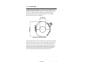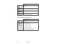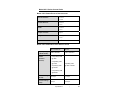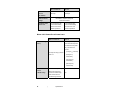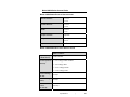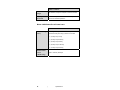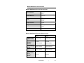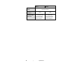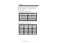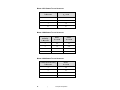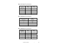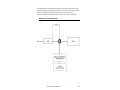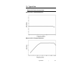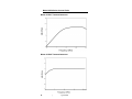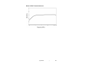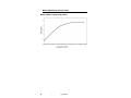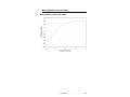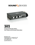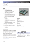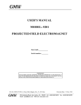
1
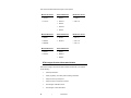
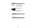
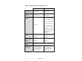
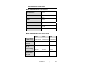
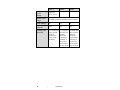
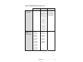
Current Probes User Manual ETS-Lindgren L.P. reserves the right to make changes to any product described herein in order to improve function, design, or for any other reason. Nothing contained herein shall constitute ETS-Lindgren L.P. assuming any liability whatsoever arising out of the application or use of any product or circuit described herein. ETS-Lindgren L.P. does not convey any license under its patent rights or the rights of others. © Copyright 2008 by ETS-Lindgren L.P. All Rights Reserved. No part of this document may be copied by any means without written permission from ETS-Lindgren L.P. Trademarks used in this document: The ETS-Lindgren logo is a trademark of ETS-Lindgren L.P. Revision Record MANUAL DESCRIPTION | Part #399297, Rev. A ii Revision Description Date A Initial Release December, 2008 | Table of Contents Notes, Cautions, and Warnings .............................................. vii 1.0 Introduction .......................................................................... 9 ETS-Lindgren Product Information Bulletin ................................................. 10 2.0 Maintenance ....................................................................... 11 Annual Calibration ....................................................................................... 11 Service Procedures ..................................................................................... 11 3.0 Specifications..................................................................... 13 Model 91197 Series Current Probe ............................................................. 13 Model 91197 Series Physical Specifications ....................................... 13 Model 91197 Series Electrical Specifications ...................................... 14 Model 91550 Series Current Probe ............................................................. 15 Model 91550 Series Physical Specifications ....................................... 15 Model 91550 Series Electrical Specifications ...................................... 15 Model 91550 Series Pulse Power Limits ............................................. 17 Model 93511 Series Current Probe ............................................................. 18 Model 93511 Series Physical Specifications ....................................... 18 Model 93511 Series Electrical Specifications ...................................... 18 Model 93686 Series Current Probe ............................................................. 19 Model 93686 Series Physical Specifications ....................................... 19 Model 93686 Series Electrical Specifications ...................................... 20 Model 94106 Series Current Probe ............................................................. 21 Model 94106 Series Physical Specifications ....................................... 21 Model 94106 Series Electrical Specifications ...................................... 21 Model 94106 Series Pulse Power Limits ............................................. 22 Model 94111 Series Current Probe ............................................................. 23 Model 94111 Series Physical Specifications ....................................... 23 Model 94111 Series Electrical Specifications ...................................... 23 Model 94111 Series Pulse Power Limits ............................................. 24 Model 94430 Series Current Probe ............................................................. 25 Model 94430 Series Physical Specifications ....................................... 25 Model 94430 Series Electrical Specifications ...................................... 25 Model 94430 Series Pulse Power Limits ............................................. 26 | iii Model 94606 Series Current Probe ............................................................. 27 Model 94606 Series Physical Specifications ....................................... 27 Model 94606 Series Electrical Specifications ...................................... 27 4.0 Principles of Operation ..................................................... 29 Circuit ........................................................................................................... 29 Basic RF Transformer.......................................................................... 30 Sensitivity ..................................................................................................... 31 Model 91197 Series Typical Sensitivity ............................................... 31 Model 91550 Series Typical Sensitivity ............................................... 31 Model 93511 Series Typical Sensitivity ............................................... 32 Model 93686 Series Typical Sensitivity ............................................... 32 Model 94106 Series Typical Sensitivity ............................................... 32 Model 94111 Series Typical Sensitivity ............................................... 33 Model 94430 Series Typical Sensitivity ............................................... 33 Model 94606 Series Typical Sensitivity ............................................... 33 Core Saturation and Intermodulation ........................................................... 34 Transfer Impedance ..................................................................................... 34 5.0 Assembly and Installation ................................................ 37 Equipment Setup to Measure RF Current ................................................... 37 For a Single Conductor ........................................................................ 37 For a Two-Conductor Cable ................................................................ 37 For Multi-Conductor Cables ................................................................. 37 To Evaluate Shielding Effectiveness ................................................... 38 Installation Instructions ................................................................................ 38 Sample Test Configuration .......................................................................... 39 6.0 Operation ............................................................................ 41 Signal Measurement .................................................................................... 42 Signal Injection ............................................................................................ 45 7.0 Typical Data ........................................................................ 47 Model 91197 Series Current Probe ............................................................. 47 Model 91197-1 Transfer Impedance ................................................... 47 Model 91197-1L Transfer Impedance ................................................. 47 Model 91550 Series Current Probe ............................................................. 48 Model 91550-1 Transfer Impedance ................................................... 48 Model 91550-2 Transfer Impedance ................................................... 48 iv | Model 91550-5 Transfer Impedance ................................................... 49 Model 93511 Series Current Probe ............................................................. 50 Model 93511-1 Transfer Impedance ................................................... 50 Model 93511-1L Transfer Impedance ................................................. 50 Model 93686 Series Current Probe ............................................................. 51 Model 93686-1 Transfer Impedance ................................................... 51 Model 93686-8 Transfer Impedance ................................................... 51 Model 94106 Series Current Probe ............................................................. 52 Model 94106-1 Transfer Impedance ................................................... 52 Model 94111 Series Current Probe ............................................................. 53 Model 94111-1 Transfer Impedance ................................................... 53 Model 94111-2 Transfer Impedance ................................................... 53 Model 94430 Series Current Probe ............................................................. 54 Model 94430-1 Transfer Impedance ................................................... 54 Model 94606 Series Current Probe ............................................................. 55 Model 94606-1 Transfer Impedance ................................................... 55 Appendix A: Warranty ............................................................. 57 | v This page intentionally left blank. vi | Notes, Cautions, and Warnings Note: Denotes helpful information intended to provide tips for better use of the product. Caution: Denotes a hazard. Failure to follow instructions could result in minor personal injury and/or property damage. Included text gives proper procedures. Warning: Denotes a hazard. Failure to follow instructions could result in SEVERE personal injury and/or property damage. Included text gives proper procedures. See the ETS-Lindgren Product Information Bulletin for safety, regulatory, and other product marking information. | vii This page intentionally left blank. viii | 1.0 Introduction The ETS-Lindgren Current Probe is a clamp-on RF current transformer that determines the intensity of RF current present in an electrical conductor or group of conductors. The current probe is designed for use with electromagnetic interference (EMI) test receivers or spectrum analyzers, or with any similar instrument having a 50-ohm input impedance. Model 93511 Series Current Probe A current probe provides a way to accurately measure net (common mode) radio frequency current flowing on a wire or bundle of wires without requiring a direct connection to the conductor(s) of interest. The probe clamps around the test conductor which becomes a one turn primary winding; the probe forms the core and secondary winding of an RF transformer. Measurements can be made on single-conductor and multi-conductor cables, grounding and bonding straps, outer conductors of shielding conduits and coaxial cables, and so on. Introduction | 9 This manual includes these ETS-Lindgren current probes: Model 91197 Series Model 91550 Series Model 93511 Series • • 91550-1 • • 91550-1L • 93511-1L 91197-1 • 91197-1L 93511-1 • 91550-2 • 91550-2L • 91550-5 Model 93686 Series Model 94106 Series Model 94111 Series • 93686-1 • 94106-1 • 94111-1 • 93686-8 • 94106-1L • 94111-1L • 93686-8L • 94111-2 Model 94430 Series Model 94606 Series • 94430-1 • 94606-1 • 94430-1L • 94606-1L • 94606-6 ETS-Lindgren Product Information Bulletin See the ETS-Lindgren Product Information Bulletin included with your shipment for the following: 10 • Warranty information • Safety, regulatory, and other product marking information • Steps to receive your shipment • Steps to return a component for service • ETS-Lindgren calibration service • ETS-Lindgren contact information | Introduction 2.0 Maintenance Before performing any maintenance, follow the safety information in the ETS-Lindgren Product Information Bulletin included with your shipment. WARRANTY Maintenance is limited to external components such as cables or connectors. If you have any questions concerning maintenance, contact ETS-Lindgren Customer Service. Annual Calibration See the Product Information Bulletin included with your shipment for information on ETS-Lindgren calibration services. Service Procedures For the steps to return a system or system component to ETS-Lindgren for service, see the Product Information Bulletin included with your shipment. Maintenance | 11 This page intentionally left blank. 12 | Maintenance 3.0 Specifications At the lower frequencies, the signal current IP level can be as great as allowed for maximum power current. When both signal and power currents are high, their sum should not exceed the given limits. L model current probes are calibrated down to 20 Hz. Model 91197 Series Current Probe MODEL 91197 SERIES PHYSICAL SPECIFICATIONS Window Diameter: 3.18 cm 1.25 in Outside Diameter: 8.26 cm 3.25 in Width: 3.56 cm 1.4 in Output Connector: Type N Weight: 0.6 kg 1 lb 5 oz Impedance: 50 Ω Specifications | 13 MODEL 91197 SERIES ELECTRICAL SPECIFICATIONS 91197-1 91197-1L 10 kHz–8 MHz 20 kHz–8 MHz Transfer Impedance 0.32 Ω ± 2 dB 0.32 Ω ± 2 dB (Nominal): 10 kHz–1 MHz 1 kHz–1 MHz Frequency Range (L Models 20 Hz): RF Current Range • >20 kHz–150 amps max (RF CW): • 10 kHz–166 amps max • 4 kHz–200 amps max • 2 kHz–250 amps max 100 amps • 1 kHz–400 amps max • 400 Hz–1000 amps ma Below 400 Hz the probe is limited by core saturation effects at an IP of 1000 amps RF Current Range 100 amps 100 amps (Pulse): (200 amps with reduced (200 amps with reduced duty cycle) duty cycle) 350 amps 1000 amps Maximum Power Current (DC-400 Hz): Maximum Power No limitation; subject to adequate conductor insulation Voltage: Sensitivity Under 30 microamperes with 30 microamperes with Rated Load: 1 microvolt sensitivity 1 microvolt sensitivity receiver and 0.33 ohm receiver and 0.33 ohm transfer impedance transfer impedance 14 | Specifications Model 91550 Series Current Probe MODEL 91550 SERIES PHYSICAL SPECIFICATIONS 3.18 cm Window Diameter: 1.25 in 8.89 cm Outside Diameter: 3.5 in 7.29 cm Width: 2.87 in Output Connector: Type N Weight: 0.6 kg 1.31 lb 50 Ω Impedance: MODEL 91550 SERIES ELECTRICAL SPECIFICATIONS 91550-1 91550-2 91550-5 10 kHz–100 MHz 10 kHz–150 MHz 10 kHz–200 MHz Transfer Impedance 5.0 Ω ± 3 dB 1.0 Ω ± 2 dB 1.0 Ω ± 2 dB (Nominal): 1 MHz–100 MHz 1 MHz–150 MHz 1 MHz–100 MHz 42 amps 2.8 amps 2.3 amps 100 amps 100 amps 100 amps 350 amps 350 amps 350 amps Frequency Range (L Models 20 Hz): RF Current Range (RF CW): RF Current Range (Pulse): Maximum Power Current (DC–60 Hz): Specifications | 15 91550-1 Maximum Power 350 amps, Current 91550-2 91550-5 225 amps 225 amps 50 Hz–1500 Hz (400 Hz): Maximum Power No limitation; subject to adequate conductor insulation Voltage: Internal Loading: Rated Ouptut Load Impedance: No Yes No 50 Ω 50 Ω 50 Ω Sensitivity Under 0.17 microampere 1.0 microampere 1.0 microampere Rated Load: with 1 microvolt with 1 microvolt with 1 microvolt sensitivity sensitivity sensitivity receiver and receiver and receiver and 6 ohm transfer 1 ohm transfer 1 ohm transfer impedance impedance, or impedance, or 10 mV across 10 mV across 50 ohm load for 50 ohm load for 0.01 amp signal 0.01 amp signal 16 | Specifications MODEL 91550 SERIES PULSE POWER LIMITS 91550-1 RF Current 100 amps Range (Pulse): 91550-2 91550-5 Pulse signals with 100 amps with peak currents to maximum pulse 100 amps can be duty cycle not to measured if the exceed 0.002 for pulse duty cycle 100 amp signal does not exceed: • (10 amps IP) 0.080 Duty • (30 amps IP) 0.010 Duty • (50 amps IP) 0.003 Duty • (100 amps IP) 0.001 Duty Maximum Power Current (L Models Only): • (2 MHz) 50 amps • (1 MHz) 60 amps • (0.5 MHz) 85 amps • (60 Hz) NA 650 amps • (120 Hz) 650 amps • (400 Hz) 500 amps • (0.2 MHz) • (1500 Hz) 175 amps 140 amps • (0.1 MHz) 340 amps • (0.05 MHz) 650 amps Specifications | 17 Model 93511 Series Current Probe MODEL 93511 SERIES PHYSICAL SPECIFICATIONS 3.18 cm Window Diameter: 1.25 in 8.26 cm Outside Diameter: 3.25 in 3.56 cm Width: 1.4 in Output Connector: Type N Weight: 0.6 kg 1 lb 5 oz 50 Ω Impedance: MODEL 93511 SERIES ELECTRICAL SPECIFICATIONS 93511-1 93511-1L 10 kHz–30 MHz 20 kHz–30 MHz Transfer Impedance 1 Ω (0 db) ± 2 dB 1 Ω (0 db) ± 2 dB (Nominal): 100 kHz–10 MHz 100 kHz–10 MHz 100 amps 100 amps 200 amps 200 amps 350 amps 800 amps Frequency Range (L Models 20 Hz): RF Current Range (RF CW): RF Current Range (Pulse): Maximum Power Current (DC–60 Hz): 18 | Specifications 93511-1 93511-1L 350 amps 800 amps Maximum Power Current (400 Hz): Maximum Power Voltage: No limitation; subject to adequate conductor insulation Sensitivity Under 1.0 microampere with 1.0 microampere with Rated Load: 1 microvolt sensitivity 1 microvolt sensitivity receiver and 1 ohm receiver and 1 ohm transfer impedance transfer impedance Model 93686 Series Current Probe MODEL 93686 SERIES PHYSICAL SPECIFICATIONS Window Diameter: 6.65 cm 2.62 in Outside Diameter: 13.97 cm 5.5 in Width: 5.38 cm 2.12 in Output Connector: Type N Weight: 2.27 kg 5 lb Impedance: 50 Ω Specifications | 19 MODEL 93686 SERIES ELECTRICAL SPECIFICATIONS 93686-1 93686-8 10 kHz–30 MHz 10 kHz–200 MHz Transfer Impedance 2.0 Ω ± 2 dB 8.0 Ω ± 3 dB (Nominal): 100 kHz–10 MHz 10 MHz–200 MHz 0 amps–200 amps 0 amps–62 amps 200 amps 62 amps 350 amps 300 amps 350 amps 300 amps Frequency Range (L Models 20 Hz): RF Current Range (RF CW): RF Current Range (Pulse): Maximum Power Current (DC–60 Hz): Maximum Power Current (400 Hz): Maximum Power No limitation; subject to adequate conductor insulation Voltage: Sensitivity Under 0.5 microampere with 0.125 microampere with Rated Load: 1 microvolt sensitivity 1 microvolt sensitivity receiver and 2 ohm receiver and 8 ohm transfer impedance transfer impedance 20 | Specifications Model 94106 Series Current Probe MODEL 94106 SERIES PHYSICAL SPECIFICATIONS 3.18 cm Window Diameter: 1.25 in 8.26 cm Outside Diameter: 3.25 in 3.56 cm Width: 1.4 in Output Connector: Type N Weight: 0.43 kg 15 oz 50 Ω Impedance: MODEL 94106 SERIES ELECTRICAL SPECIFICATIONS 94106-1 Frequency Range (L Models 20 Hz): Transfer Impedance (Nominal): RF Current Range (RF CW): RF Current Range (Pulse): 100 kHz–450 MHz • 2 Ω (6 db) ± 3 dB @ 1 MHz • 6 Ω (15.5 db) ± 3 dB @ 100 MHz—450 MHz 20 amps 50 amps Maximum Power Current 200 amps (DC–60 Hz): Specifications | 21 94106-1 Maximum Power 200 amps Current (400 Hz): Maximum Power No limitation; subject to adequate conductor insulation Voltage: Rated Output Load 50 Ω Impedance: Sensitivity Under 0.1 microampere with 1 microvolt sensitivity receiver Rated Load: and 10 ohm transfer impedance MODEL 94106 SERIES PULSE POWER LIMITS 94106-1 / 94106-1L RF Current Range 50 amps (Pulse): Maximum Power • (DC to 60 Hz) 300 amps Current • (DC to 120 Hz) 300 amps (L Models Only): • (DC to 400 Hz) 300 amps • (DC to 1500 Hz) 300 amps When both signal and power currents are high, their sum should not exceed the given limits 22 | Specifications Model 94111 Series Current Probe MODEL 94111 SERIES PHYSICAL SPECIFICATIONS 3.18 cm Window Diameter: 1.25 in 8.89 cm Outside Diameter: 3.5 in 3.56 cm Width: 1.4 in Type N Output Connector: 0.42 kg Weight: 15 oz 50 Ω Impedance: MODEL 94111 SERIES ELECTRICAL SPECIFICATIONS Frequency Range (L Models 20 HZ): Transfer Impedance (Nominal): 94111-1 / 94111-1L 94111-2 1 MHz–1000 MHz 1 MHz–1000 MHz • 0.9Ω(-1dB Ω) ±3dB @1 MHz • 2.5Ω(8dB Ω) ±3dB @10 MHz • 5Ω(14dB Ω) ±3dB 1Ω(0dB Ω) ±3dB @1 MHz–100 MHz @100 MHz • 5.6Ω(15dB Ω) ±3dB @500 MHz RF Current Range (RF CW): RF Current Range (Pulse): 20.0 amps 1.7 amps 50 amps 200 amps Specifications | 23 94111-1 / 94111-1L 94111-2 200 amps 200 amps Maximum Power Current (DC–400 Hz): No limitation; subject to adequate Maximum Power conductor insulation Voltage: Sensitivity Under 0.2 microampere with 1 microampere with Rated Load: 1 microvolt sensitivity 1 microvolt sensitivity receiver and 5 ohms receiver and 1 ohm transfer impedance transfer impedance MODEL 94111 SERIES PULSE POWER LIMITS 94111-1 / 94111-1L 94111-2 RF Current Range Pulse signals with peak (Pulse): currents to 200 amps can be measured if the pulse duty cycle does not exceed: 50 amps for duty cycle less • (10 amps IP) 0.06 Duty • (50 amps IP) than 0.4 0.0024 Duty • (100 amps IP) 0.0006 Duty • (200 amps IP) 0.00015 Duty Maximum Power (DC to 1500 Hz) 300 amps Current When both signal and (L Models Only): power currents are high, their sum should not exceed the given limits 24 | Specifications NA Model 94430 Series Current Probe MODEL 94430 SERIES PHYSICAL SPECIFICATIONS 1.91 cm Window Diameter: 0.75 in 5.72 cm Outside Diameter: 2.25 in 2.54 cm Width: 1.0 in Type BNC Output Connector: 0.18 kg Weight: 6.5 oz 50 Ω Impedance: MODEL 94430 SERIES ELECTRICAL SPECIFICATIONS 94430-1 / 94430-1L Frequency Range (L Models 20 Hz): Transfer Impedance (Nominal): 10 kHz–250 MHz • 6 Ω ± 2 dB @ 10 MHz–250 MHz • 3 Ω ± 2 dB @ 1 MHz • 0.6 Ω ± 3 dB @ 100 kHz • 0.1 Ω ± 3 dB @ 10 kHz RF Current Range (RF CW): RF Current Range (Pulse): 16 amps 70 amps Maximum Power Current 200 amps (DC–400 Hz): Specifications | 25 94430-1 / 94430-1L Maximum Power No limitation; subject to adequate conductor insulation Voltage: Sensitivity Under 0.125 microampere with 1 microvolt sensitivity receiver Rated Load: and 8 ohm transfer impedance MODEL 94430 SERIES PULSE POWER LIMITS 94430-1 / 94430-1L RF Current Range Pulse signals with peak currents to 70 amps can be (Pulse): measured if the pulse duty cycle does not exceed: • (16 amps IP) 1.0 Duty • (25 amps IP) 0.625 Duty • (40 amps IP) 0.39 Duty • (50 amps IP) 0.3125 Duty • (70 amps IP) 0.227 Duty Maximum Power (DC to 1500 Hz) 400 amps Current (L Models Only): 26 | Specifications Model 94606 Series Current Probe MODEL 94606 SERIES PHYSICAL SPECIFICATIONS 12.7 cm Window Diameter: 5.0 in 19.81 cm Outside Diameter: 7.8 in 5.38 cm Width: 2.12 in Output Connector: Type N Weight: 3.18 kg 7.0 lb 50 Ω Impedance: MODEL 94606 SERIES ELECTRICAL SPECIFICATIONS Frequency Range (L Models 20 HZ): Transfer Impedance (Nominal): RF Current Range (RF CW): RF Current Range (Pulse): 94606-1 94606-6 10 kHz–100 MHz 1 kHz–5 MHz 5 Ω ±4dB 1 Ω ±2dB @1 MHz–100 MHz @10 kHz–5 MHz 0 amps–100 amps 0 amps–300 amps 0 amps–100 amps 0 amps–400 amps 350 amps 350 amps Maximum Power Current (DC–60 Hz) (400 Hz): Specifications | 27 94606-1 Maximum Power 94606-6 No limitation; subject to adequate conductor insulation Voltage: Rated Output Load Impedance: 28 50 Ω 50 Ω Sensitivity Under 0.2 microampere with 1 microampere with Rated Load: 1 microvolt sensitivity 1 microvolt sensitivity receiver and 5 ohms receiver and 1 ohm transfer impedance transfer impedance | Specifications 4.0 Principles of Operation Before connecting any components or operating the probe, follow the safety information in the ETS-Lindgren Product Information Bulletin included with your shipment. The current probe is an inserted-primary type of radio frequency current transformer. When the probe is clamped over the conductor or cable in which current is to be measured, the conductor forms the primary winding. The clamp-on feature of this probe enables easy placement around any conductor or cable. Circuit The circuit is that of a radio frequency transformer, as illustrated on page 30. Because the current probe is intended for clamp-on operation, the primary shown on page 30 is the electrical conductor in which interference currents are to be measured. This primary is considered as one turn since it is assumed that the noise currents flow through the conductor and return to the source by way of a ground conductor such as a frame, common ground plane, or earth. On some current probe models the secondary output terminals are resistively loaded internally to provide substantially constant transfer impedance over a wide frequency range. Principles of Operation | 29 BASIC RF TRANSFORMER 30 | Principles of Operation Sensitivity Probe sensitivity in microamperes depends on the sensitivity in microvolts of the receiving equipment with which it is used. The following tables show the relationship of receiving sensitivity in microvolts to the overall sensitivity of the probe and receiver in microamperes. This data is based on the transfer impedance of each model. MODEL 91197 SERIES TYPICAL SENSITIVITY Test Equipment Sensitivity 91197-1 in Microvolts ZT = 0.33 Ω 4 12.1 2 6.0 1 3.0 0.1 0.3 MODEL 91550 SERIES TYPICAL SENSITIVITY Test Equipment 91550-1 91550-2 91550-5 Sensitivity ZT = 5.0 Ω ZT = 1.0 Ω ZT = 1.0 Ω 5 1 5 5 2 0.4 2 2 1 0.2 1 1 0.1 0.02 0.1 0.1 in Microvolts Principles of Operation | 31 MODEL 93511 SERIES TYPICAL SENSITIVITY Test Equipment Sensitivity 93511-1 in Microvolts ZT = 1.0 Ω 4 4.0 2 2.0 1 1.0 0.1 0.1 MODEL 93686 SERIES TYPICAL SENSITIVITY Test Equipment 93686-1 93686-8 in Microvolts ZT = 2.0 Ω ZT = 8.0 Ω 4 2.0 0.5 2 1.0 0.25 1 0.5 0.125 0.1 0.05 0.0125 Sensitivity MODEL 94106 SERIES TYPICAL SENSITIVITY 32 Test Equipment Sensitivity 94106-1 in Microvolts ZT = 5.0 Ω 4 0.8 2 0.4 1 0.2 0.1 0.02 | Principles of Operation MODEL 94111 SERIES TYPICAL SENSITIVITY Test Equipment 94111-1 94111-2 in Microvolts ZT = 5.0 Ω ZT = 1.0 Ω 5 1 5 2 0.4 2 1 0.2 1 0.1 0.02 0.1 Sensitivity MODEL 94430 SERIES TYPICAL SENSITIVITY Test Equipment Sensitivity 94430-1 in Microvolts ZT = 6.0 Ω 5 0.625 2 0.25 1 0.125 0.1 1.0125 MODEL 94606 SERIES TYPICAL SENSITIVITY Test Equipment 94606-1 94606-6 in Microvolts ZT = 5.0 Ω ZT = 1.0 Ω 4 0.8 4 2 0.4 2 1 0.2 1 0.1 0.02 0.1 Sensitivity Principles of Operation | 33 Core Saturation and Intermodulation The magnetizing effects of a primary conductor carrying large currents at power line frequencies can saturate the current probe core material. Core saturation produces non-linear transforming action and can result in: • A decrease in the current probe RF output for a given RF current input. • Modulation of the RF output by the power line frequency. The specified pulse duty cycle should not be exceeded or the current probe internal load resistor (if applicable) may be subject to damage. The load resistor must also be protected from excessive line currents. The influence of intermodulation on the current probe output as measured with the EMI test equipment is negligible for primary conductor power frequency currents under 300 amperes. For primary power currents above 300 amperes, measurements taken by the EMI test equipment generally will not be affected by intermodulation due to the averaging characteristics for the quasi-peak and peak functions; the readings will increase with current. Transfer Impedance The RF current (IP) in microamps in the conductor under test is determined from the reading of the current probe output in microvolts (ES) divided by the current probe transfer impedance (ZT). IP ES ZT Or, in dB: IP dBμA 34 | ES dBμV ZT dB Principles of Operation The typical transfer impedance of the current probe throughout the frequency range is shown in Typical Data on page 47. It is determined by passing a known RF current (IP) through the primary test conductor and noting the voltage (ES), developed across a 50-ohm load. ZT ES IP Principles of Operation | 35 This page intentionally left blank. 36 | Principles of Operation 5.0 Assembly and Installation Before connecting any components, follow the safety information in the ETS-Lindgren Product Information Bulletin included with your shipment. Equipment Setup to Measure RF Current Standing waves can exist on the test conductor under test at or near the resonant frequency. Under these conditions, several measurements taken along the line will provide a complete picture of the RF current distribution and amplitude. FOR A SINGLE CONDUCTOR 1. Place the probe jaws around the conductor so that the conductor passes through the center opening. 2. Lock the jaws together. FOR A TWO-CONDUCTOR CABLE • To evaluate the common mode component of the noise current (the net effect of the currents leaving and returning): Place the probe over both conductors at the same time. • To measure the interference current in either conductor separately: Place the probe over each wire individually. FOR MULTI-CONDUCTOR CABLES The probe will measure the net external effects of all the currents in the conductors that pass through the center of the probe. Assembly and Installation | 37 TO EVALUATE SHIELDING EFFECTIVENESS When placed over shielding conduit, coaxial cable, or ignition shielding, the probe measures the current flowing on the external surface of the shield. Installation Instructions The window (aperture) of the probe will accommodate cables up to the following maximum outside diameters. Current Probe Maximum Outside Diameter Model 91197 Series 1.25 inches Model 91550 Series 1.25 inches Model 93511 Series 1.25 inches Model 94106 Series 1.25 inches Model 94111 Series 1.25 inches Model 94430 Series 0.75 inches Model 93686 Series 2.62 inches Model 94606 Series 5.0 inches For greatest accuracy, the conductor under measurement should be centered in the window of the current probe. Place the probe around the conductor(s) to be measured and then carefully lock the probe jaws. Otherwise, inadequate shielding or incorrect air gap will result and the measurement will not be accurate. The connecting cable used between the current probe and the EMI test equipment must have 50-ohm characteristic impedance and matching cable connectors. The current probe is calibrated for use only with a 50-ohm load. Therefore, the EMI test equipment must have a 50-ohm input impedance. Observe precautions regarding minimum bending radius when installing and using the cable. For long cables and at high frequencies, cable loss may also be a factor. Use low loss cables and perform cable loss corrections if necessary. 38 | Assembly and Installation The probe rejection of any external pickup from conductors not passing through the window is better than 60 dB. The presence of very strong magnetic fields will likely have an effect on probe sensitivity. Do not place the unit close to permanent magnets or the magnetic field structures of motors or generators. Sample Test Configuration Assembly and Installation | 39 This page intentionally left blank. 40 | Assembly and Installation 6.0 Operation Before connecting any components, follow the safety information in the ETS-Lindgren Product Information Bulletin included with your shipment. If measuring uninsulated conductors: Use extreme care when installing the current probe and taking measurements. If possible, de-energize the test sample during assembly and disassembly of the setup. Also, arrange to center the test conductor in the current probe window for additional voltage breakdown protection. Do not permit the uninsulated current probe connector and cable connectors to come in contact with the ground plane or other nearby conductors. This will prevent possible measurement error due to ground loops, and will avoid danger from high voltages. Ensure that the 50-ohm load is capable of safely dissipating the incurred power. Should the load become disconnected, the developed voltage will be come much greater and may be very dangerous. The RF current probe is a broadband RF transformer for use with EMI test equipment. Radio frequency currents can be measured in cables without physically disturbing the circuit. Operation | 41 Signal Measurement OSCILLOSCOPE USE: IN TERMS OF RF AMPERES 1. Standardize the gain of the oscilloscope to correctly read the voltage (ES) applied to the input terminals. 2. Divide ES in volts by the average current probe transfer impedance ZT in ohms. The result is the value of the RF signal in terms of amperes in the test conductor. Example: Assume an oscilloscope peak voltage measurement of 5 volts and the average ZT to be 1.06 ohms. Then: 5/1.06 = 4.71 amperes in the test conductor. The example is valid providing that the oscilloscope rise time (T = 0.3/BW) is shorter than RF signal pulse duration. This also applies to the current probe which has a rise time of about 3 nanoseconds based on a 100 megahertz bandwidth. IN TERMS OF dB ABOVE ONE MICROAMPERE AT METER INPUT (CW CONDUCTED MEASUREMENTS) 1. Adjust the EMI test equipment for standard gain and make a measurement of the CW signal (voltage output from the current probe) in terms of dB above one microvolt. Use procedures outlined in the EMI test equipment instruction manual. 2. Subtract the transfer impedance of the current probe in dB at the test frequency from the dB measurement of the previous step. The result is the value of the conducted CW signal in terms of dB above one microamp at meter input. At meter input as used in the MIL-I-26600 and MIL-I-6181D specifications refers to the current in the test sample lead. 42 | Operation Example: Frequency is 10.0 kHz; step 1 measurement is 52 dB above one microvolt. For example, suppose the transfer impedance of the current probe used in the example was 8.0 dB below one ohm at 10.0 kHz. Then, as outlined in step 2: 52 dB + 8.0 dB = 60 dB above one microampere at meter input. IN TERMS OF dB ABOVE ONE MICROAMPERE PER MEGAHERTZ AT METER INPUT (BROADBAND INTERFERENCE MEASUREMENT) 1. Adjust the EMI test equipment for standard gain and make a peak measurement of the broadband interference (voltage output from the current probe) in terms of dB above one microvolt per megahertz. Use procedures outlined in the EMI test equipment instruction manual. 2. Subtract the transfer impedance of the current probe in dB at the test frequency from the dB measurement of the previous step. The result is the value of the broadband interference in terms of dB above one microamp per megahertz at meter input. At meter input as used in the MIL-I-26600 and MIL-I-6181D specifications refers to the current in the test sample lead. Example: Frequency is 100 kHz; step 1 measurement is 41 dB above one microvolt per megahertz. For example, suppose the transfer impedance of the current probe was 8.0 dB below one ohm at 100 kHz. Then, as outlined in step 2: 41 dB + 8.0 dB = 49 dB above one microamp per megahertz at meter input. This result is beyond the limit of 46.2 dB above one microamp per megahertz. Operation | 43 IN TERMS OF MICROAMPERE IN TEST SAMPLE LEAD (CW CONDUCTED MEASUREMENTS) 1. Adjust the EMI test equipment for standard gain and make a measurement of the CW signal (voltage output from current probe) in terms of microvolts at meter input. Use procedures outlined in the EMI test equipment instruction manual. 2. Divide the microvolt measurement of the previous step by the transfer impedance in ohms at the test frequency. The result is the value of conducted CW signal in terms of microamperes in the test sample lead. Example: Frequency is 3.0 kHz; step 1 measurement is 150 microvolts. For example, suppose the transfer impedance of the current probe was 0.34 ohms. Then, as outlined in step 2, 150/0.34 = 441.1 microamperes in the test sample lead. IN TERMS OF MICROAMPERE PER MEGAHERTZ IN TEST SAMPLE LEAD (BROADBAND INTERFERENCE MEASUREMENT) 1. Adjust the EMI test equipment for standard gain and make a measurement of the broadband interference (voltage output from current probe), in terms of microvolts per megahertz at meter input. Use procedures outlined in the EMI test equipment instruction manual. 2. Divide the microvolt per megahertz measurement of the previous step by the transfer impedance in ohms at the test frequency. The result is the value of conducted broadband interference in terms of microamps per megahertz in the test sample lead. Example: Frequency is 10.0 kHz; step 1 measurement is 8000 microvolts per megahertz. For example, suppose the transfer impedance of the current probe was 0.39 ohms. Then, as outlined in step 2, 8000/0.39 = 20513 microamps per megahertz in test sample lead. 44 | Operation Signal Injection Applies to Model 94111 Series only. Current probes may be used to inject RF currents into test conductors when performing susceptibility tests. Injection is best accomplished with current probes that do not have internal loading. Internal loading will absorb part (or most) of the driving power and can seriously limit the maximum levels of voltage and current that the current probe can handle as an injection device. The current probe does not have an internal load and therefore is suited for signal injection. However, it will be limited by connector voltage rating (500 V) and by the thermal limit of the coil windings. A maximum continuous injection current into the current probe coils of 4.2 amps may be used; two or three times this level may be used for short periods of time. When injecting pulse signals, the average current should be held within the above limits, and the peak voltage held below 500 V. Because of variable circuit impedances, there is no easy way to compute the RF current that may be injected into the test conductor. The practical way to determine the injected current is to measure it with a second current probe on the test conductor. The second current probe can be any model that covers the frequency range of interest. Operation | 45 This page intentionally left blank. 46 | Operation 7.0 Typical Data Model 91197 Series Current Probe MODEL 91197-1 TRANSFER IMPEDANCE MODEL 91197-1L TRANSFER IMPEDANCE Typical Data | 47 Model 91550 Series Current Probe MODEL 91550-1 TRANSFER IMPEDANCE MODEL 91550-2 TRANSFER IMPEDANCE 48 | Typical Data MODEL 91550-5 TRANSFER IMPEDANCE Typical Data | 49 Model 93511 Series Current Probe MODEL 93511-1 TRANSFER IMPEDANCE MODEL 93511-1L TRANSFER IMPEDANCE 50 | Typical Data Model 93686 Series Current Probe MODEL 93686-1 TRANSFER IMPEDANCE MODEL 93686-8 TRANSFER IMPEDANCE Typical Data | 51 Model 94106 Series Current Probe MODEL 94106-1 TRANSFER IMPEDANCE 52 | Typical Data Model 94111 Series Current Probe MODEL 94111-1 TRANSFER IMPEDANCE MODEL 94111-2 TRANSFER IMPEDANCE Typical Data | 53 Model 94430 Series Current Probe MODEL 94430-1 TRANSFER IMPEDANCE 54 | Typical Data Model 94606 Series Current Probe MODEL 94606-1 TRANSFER IMPEDANCE Typical Data | 55 This page intentionally left blank. 56 | Typical Data Appendix A: Warranty See the Product Information Bulletin included with your shipment for the complete ETS-Lindgren warranty. DURATION OF WARRANTIES All product warranties, except the warranty of title, and all remedies for warranty failures are limited to two years. Product Warranted Duration of Warranty Period Model 91197 Series Current Probe 2 Years Model 91550 Series Current Probe 2 Years Model 93511 Series Current Probe 2 Years Model 93686 Series Current Probe 2 Years Model 94106 Series Current Probe 2 Years Model 94111 Series Current Probe 2 Years Model 94430 Series Current Probe 2 Years Model 94606 Series Current Probe 2 Years Warranty | 57