1
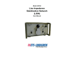
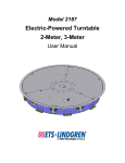
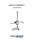
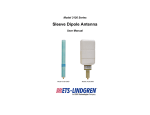
Model 95236-1 / Model 95242-1
Bulk Current
Injection Probes
User Manual
ETS-Lindgren L.P. reserves the right to make changes to any product described
herein in order to improve function, design, or for any other reason. Nothing
contained herein shall constitute ETS-Lindgren L.P. assuming any liability
whatsoever arising out of the application or use of any product or circuit
described herein. ETS-Lindgren L.P. does not convey any license under its
patent rights or the rights of others.
© Copyright 2001–2010 by ETS-Lindgren L.P. All Rights Reserved. No part
of this document may be copied by any means without written permission
from ETS-Lindgren L.P.
Trademarks used in this document: The ETS-Lindgren logo is a trademark of
ETS-Lindgren L.P.
Revision Record
MANUAL, CURRENT PROBE, 95236,95242 | Part #399263, Rev. D
Revision
Description
Date
A
Initial Release
October, 2001
B
Updates/edits
March, 2002
C
Updates/edits
February, 2005
Remove Model 95252-1; update
June, 2010
D
frequency range specifications;
rebrand
ii
|
Table of Contents
Notes, Cautions, and Warnings ................................................ v 1.0 Introduction .......................................................................... 7 Supporting Equipment ................................................................................... 8 Optional Injection Probe ........................................................................ 8 Model 95241-1 Calibration Jig ............................................................... 8 Current Monitoring probes ..................................................................... 8 Operation: Precautionary Measures .............................................................. 9 ETS-Lindgren Product Information Bulletin ................................................. 10 2.0 Maintenance ....................................................................... 11 Annual Calibration ....................................................................................... 11 Service Procedures ..................................................................................... 11 3.0 Specifications..................................................................... 13 Physical Specifications ................................................................................ 13 Electrical Specifications ............................................................................... 14 4.0 Application ......................................................................... 17 Conducted Susceptibility ............................................................................. 17 Typical Test Setup ............................................................................... 17 Test Setup Equipment ................................................................................. 18 Sample Conducted Susceptibility Calibration Setup Diagrams ................... 19 Diagram 1 ............................................................................................ 19 Diagram 2 ............................................................................................ 20 5.0 Conducted Emission: Transfer Impedance .................... 21 Model 95236-1 ............................................................................................. 22 Model 95242-1 ............................................................................................. 23 6.0 Insertion Loss .................................................................... 25 Equipment .................................................................................................... 25 Typical Reference Calibration Setup ........................................................... 25 Procedure .................................................................................................... 26 Appendix A: Warranty ............................................................. 27 |
iii
This page intentionally left blank.
iv
|
Notes, Cautions, and Warnings
Note: Denotes helpful information intended to
provide tips for better use of the product.
Caution: Denotes a hazard. Failure to follow
instructions could result in minor personal injury
and/or property damage. Included text gives proper
procedures.
Warning: Denotes a hazard. Failure to follow
instructions could result in SEVERE personal injury
and/or property damage. Included text gives proper
procedures.
See the ETS-Lindgren Product Information Bulletin for safety,
regulatory, and other product marking information.
|
v
This page intentionally left blank.
vi
|
1.0 Introduction
The ETS-Lindgren Bulk Current Injection Probe (BCIP) Series is used to
inject RF current into conductors and cables of electrical and electronic
equipment undergoing susceptibility testing. This manual includes information for
these BCIP models:
•
Model 95236-1
•
Model 95242-1
The BCIP provides a means of applying a controlled RF stress level to an
instrument under test through interconnecting cables or power cables without
requiring a direct connection to the conductor(s) of interest. The models in this
series are simply clamped around the test conductor which then becomes a
one turn secondary winding, with the current probe forming the core and primary
winding of an RF transformer. RF energy can be injected onto single and
multi-conductor cables, grounding and bonding straps, outer conductors of
shielding conduits and coaxial cables, and so on.
Because of the high efficiency design, the probes can also be used as sensors.
Frequency Range*
Useful Range
95236-1
1 MHz–100 MHz
10 kHz–100 MHz
95242-1
10 MHz–400 MHz
2 MHz–400 MHz
*
The BCIP Series is especially designed to provide minimum insertion loss
over these frequency ranges.
Introduction
|
7
Supporting Equipment
Contact ETS-Lindgren for sizes and sensitivities of other current
probes.
When using the Model 95242-1 to perform susceptibility tests, the following
equipment may be required.
OPTIONAL INJECTION PROBE
The Model 93686-1 Current Probe with a 6.6 cm window diameter may be used
as a bulk current injection probe over the frequency range 50 kHz to 2 MHz.
MODEL 95241-1 CALIBRATION JIG
The Model 95241-1 Calibration Jig is used in equipment setup for measuring
insertion loss of the current probe and is essential to set up equipment for some
susceptibility test procedures.
CURRENT MONITORING PROBES
Suggested current monitoring probes are Model 91550-1 (10 kHz to 100 MHz)
and Model 94111-1 (1 MHz to 1 GHz). These probes have a 1.25-inch (3.2-cm)
window size and a transfer impedance of 1 ohm to 6 ohms over the 50 kHz to
400 MHz frequency range.
8
|
Introduction
Operation: Precautionary Measures
Before connecting any components, follow the
safety information in the ETS-Lindgren
Product Information Bulletin included with your
shipment.
RF fields can be hazardous. Observe
appropriate RF exposure limits.
When measuring conductors that are not
insulated, use extreme care when installing the
current probe and taking measurements. If
possible, de-energize the test sample during
assembly and disassembly of the setup. Also,
arrange to center the test conductor in the
current probe window for additional voltage
breakdown protection.
Do not permit the uninsulated current probe
connector and cable connectors to come in
contact with the ground plane or other nearby
conductors. This will prevent possible
measurement error due to ground loops, and
will avoid danger from high voltages.
Ensure that the 50-ohm load is capable of safely
dissipating the incurred power. Should the load
become disconnected, the developed voltage
will be come much greater and may be very
dangerous.
Introduction
|
9
ETS-Lindgren Product Information Bulletin
See the ETS-Lindgren Product Information Bulletin included with your shipment
for the following:
10
•
Warranty information
•
Safety, regulatory, and other product marking information
•
Steps to receive your shipment
•
Steps to return a component for service
•
ETS-Lindgren calibration service
•
ETS-Lindgren contact information
|
Introduction
2.0 Maintenance
Before performing any maintenance,
follow the safety information in the
ETS-Lindgren Product Information
Bulletin included with your shipment.
Maintenance of the Bulk Current Injection
WARRANTY
Probe is limited to external components
such as cables or connectors.
If you have any questions concerning
maintenance, contact ETS-Lindgren
Customer Service.
Annual Calibration
See the Product Information Bulletin included with your shipment for information
on ETS-Lindgren calibration services.
Service Procedures
For the steps to return a system or system component to ETS-Lindgren for
service, see the Product Information Bulletin included with your shipment.
Maintenance
|
11
This page intentionally left blank.
12
|
Maintenance
3.0 Specifications
Physical Specifications
Window Diameter:
4.0 cm (1.57 in)
Outside Diameter:
13.0 cm (5.11 in)
At Widest Point:
10.2 cm (4.01 in)
Height:
6.0 cm (2.36 in)
Weight:
1.60 kg (3.52 lb)
Output Connector:
Type N
Input Impedance:
50 Ω
Specifications
|
13
Electrical Specifications
95236-1
95242-1
1 MHz–100 MHz
10 MHz–400 MHz
100 W*
200 W**
20 Amperes
60 Amperes
80°C
80°C
35°C
35°C
30 minutes
30 minutes
Turns Ratio:
1:2
1:1
Inductance:
47 μH, ±20%
0.8 μH, ±20%
Frequency Range:
Maximum Input
Power:
Maximum Input
Current:
Maximum Core
Temperature:
Recommended
Maximum
Temperature Rise:
Maximum Time for
Continuous Rating at
Full Power:
*
95236-1: The power limit of the 95236-1 is 100 W. Powers in excess of
75 W should be used with care to avoid excessive temperature in the
equipment under test. Prolonged testing should be avoided, particularly if
unattended.
**
95242-1: The power limit of the 95242-1 is 200 W. Powers in excess of
100 W should be used with care to avoid excessive temperature in the
equipment under test. Prolonged testing should be avoided, particularly if
unattended.
14
|
Specifications
Insertion Loss (Typical)
Useful Range
95236-1
95242-1
dB
Range
< 15 dB
1 MHz–100 MHz
-35 db ± 3 dB
@ 10 kHz
< 15 dB
10 MHz–400 MHz
10 kHz–100 MHz
2 MHz–400 MHz
Specifications
|
15
This page intentionally left blank.
16
|
Specifications
4.0 Application
The principal use of the Bulk Current Injection Probe (BCIP) is for inducing
relatively large RF currents into the signal and power circuits of equipment under
test for conducted susceptibility. A secondary application would be to use the
same probe in a more familiar role as a sensor for measuring weak conducted
RF currents.
Conducted Susceptibility
Conducted susceptibility testing is intended to ensure that RF signals, when
coupled on to interconnecting cables and power supply lines of a device under
test (DUT), will not cause malfunction or degradation of performance. In addition,
this testing can provide an amplitude vs. frequency malfunction signature for the
system which, when compared with the levels of current on the cables in a typical
operating environment, can assist in the determination of adequate safety
margins.
TYPICAL TEST SETUP
Typical conducted susceptibility tests require that all power and interconnecting
cables be tested by subjecting them to the required current or voltage levels,
while monitoring the applied current using a current probe. Usually, a reference
level calibration is performed using a calibration jig with a specified impedance.
This reference curve is then replayed to expose the DUT to a controlled stress
level, while a current probe is used to ensure that a low impedance DUT is not
overstressed.
Some tests may allow the reference calibration to be performed at a
lower level and then scaled up to the required power level when
applied to the DUT.
Entire cables or cable bundles may be tested, or each line may be broken out
and tested individually. Some standards may also require simultaneous injection
onto multiple cable bundles using several injection probes. Absorbing clamps
may be required to isolate peripheral equipment from the DUT, and ensure that
only the DUT is exposed to the required stress level. See the pertinent test
standard for more details.
Application
|
17
Test Setup Equipment
The following equipment may be needed to set up the test environment.
• Current Injection Probes:
95236-1
95242-1
• Calibration Jig 95241-1
• Current Monitoring Probes
• Signal Source/Generator
• Power Amplifier(s):
The power amplifier should be capable of
supplying the full rated power into the current
injection probes (which have a high VSWR)
with a low harmonic content.
• Spectrum Analyzer or Measuring Receivers
• Directional Coupler
• RF Voltmeter(s)
• RF Absorbing Clamp
• RF Attenuator
• RF Loads
18
|
Application
Sample Conducted Susceptibility Calibration
Setup Diagrams
DIAGRAM 1
Application
|
19
DIAGRAM 2
20
|
Application
5.0 Conducted Emission: Transfer Impedance
The Bulk Current Injection Probe (BCIP) may also be used as a sensor for
measuring conducted emission. The RF current IP (in microamperes) in the
conductor under test is determined from the measuring receiver reading of the
probe output ES (in microvolts) divided by the probe transfer impedance ZT
(in ohms).
IP = ES / ZT
Or, in dB:
IP(dBµA) = ES(dBµV) – ZT(dB)
The transfer impedance is determined by passing a known RF current IP through
the primary test conductor and noting the voltage ES developed across a 50 ohm
load on the probe output.
ZT = ES / IP
Calibration gig 95241-1 may be used for this determination. Following are the
typical transfer impedance values when the BCIP is used as a sensor.
High sensitivity and minimal core gap indicate that the current probe
should be used only on signal lines where heavy currents are not
encountered. Heavy currents may affect measurement accuracy
should current probe core saturation occur.
Conducted Emission: Transfer Impedance
|
21
Model 95236-1
22
|
Frequency (MHz)
ZT (Ω)
1
16
2
20
3
19
4
19
5
19
6
19
7
19
8
19
9
19
10
19
20
18
30
18
40
17
50
16
60
15
70
14
80
13
90
12
100
11
Conducted Emission: Transfer Impedance
Model 95242-1
Frequency (MHz)
ZT (Ω)
2
7
4
13
6
19
8
22
10
27
20
25
30
27
40
30
50
32
60
32
70
32
80
30
90
30
100
30
200
33
300
32
400
30
Conducted Emission: Transfer Impedance
|
23
This page intentionally left blank.
24
|
Conducted Emission: Transfer Impedance
6.0 Insertion Loss
Insertion loss of the Bulk Current Injection Probe (BCIP) may be measured at low
signal levels. ETS-Lindgren offers this measurement as a calibration service. See
the Product Information Bulletin included with your shipment for information on
ETS-Lindgren calibration services.
Equipment
Signal Generator (50 Ohms):
10 kHz to 400 MHz
RF Voltmeter (50 Ohms):
10 kHz to 400 MHz
Calibration Jig:
95241-1
50 Ohm Termination:
VSWR <1.2
Bulk Injection Current Probe:
95236-1 or 95242-1
Typical Reference Calibration Setup
Insertion Loss
|
25
Procedure
1.
Connect the signal generator output directly to the RF voltmeter input
as show in Typical Reference Calibration Setup on page 25, indicated
by the dashed line. Use the same cables which connected the
calibration jig and the injection probe under test. Tune to the test
frequency and adjust the signal level for a reference of 0 dBm
indication on the RF voltmeter.
2.
Without changing control settings, connect the signal generator output
to the bulk current injection probe input and connect the calibration jig
connector to the RF voltmeter input.
3.
Note the RF voltmeter output in dB. The difference between this
reading and 0 dB is the insertion loss. In this measurement, the loss
cannot be less than 3 dB since half the injected power is absorbed by
the 50 ohm termination that is particularly loading (50%) the
calibration jig.
26
|
Insertion Loss
Appendix A: Warranty
See the Product Information Bulletin included with your shipment for
the complete ETS-Lindgren warranty for your Bulk Current
Injection Probe.
DURATION OF WARRANTIES FOR BULK CURRENT INJECTION PROBE
All product warranties, except the warranty of title, and all remedies for warranty
failures are limited to two years.
Duration of
Product Warranted
Warranty Period
Model 95236-1 Bulk Current Injection Probe
2 Years
Model 95242-1 Bulk Current Injection Probe
2 Years
Warranty
|
27