1
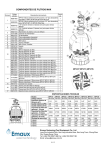
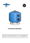
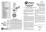
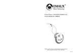
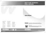
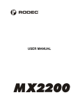
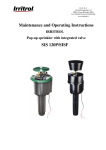
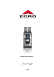
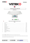
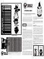
PARTS FOR FILTER MAX FILTER
Key NO. Part Number
1
Product Description
QTY
MPV07 6-Way 1.5" Clamp Type Multiport Valve for MFV17
88281505
MFV 20 MFV24 MFV27A MFV31A Filter Max
1
MPV08 6-Way 2.0" Clamp Type Multiport Valve for MFV27
MFV 31 MFV35 Filter Max
1
88280306
Water Technology
89280102 1.5" Uni on Set (3 Pieces) With O-Ring for MPV07 Valve
3
89280103 2.0" Uni on Set (3 Pieces) With O-Ring for MPV08 Valve
3
06021013 P lastic Pressure Gauge With O-Ring (40psi)
1
01111048 Connector for Pressure Gauge/Stopp er
1
4
89012512 Clamp Ki t
1
5
01271021 Clamp Lock (left)
1
6
01271022 Clamp Lock (right)
1
7
03021035 M6 Nut
1
8
01111101 S tar-Shaped Nu t
1
9
03011166 M6×110mm Screws
1
10
03018124 P in
1
11
02010007 O -Ring
1
01331024 MFV 17 Filter Tank
1
01331025 MFV 20 Filter Tank
1
01331026 MFV 24 Filter Tank
1
01331027 MFV 27A MFV2 7 Filter Tank
1
01331028 MFV 31A MFV3 1 Filter Tank
1
01331029 MFV 35 Filter Tank
1
89012507 La teral Assembly with Center Pipe for MFV17
1
89012508 La teral Assembly with Center Pipe for MFV20
1
89012509 La teral Assembly with Center Pipe for MFV24
1
89012510 La teral Assembly with Center Pipe for MFV27A
1
89012513 La teral Assembly with Center Pipe for MFV27
1
89012511 La teral Assembly with Center Pipe for MFV31A
1
89012514 La teral Assembly with Center Pipe for MFV31
1
89012515 La teral Assembly with Center Pipe for MFV35
1
01172007 La terals (115mm) for MFV17
8
01172008 La terals (126mm) for MFV20 MFV 24 MFV27A MFV31A
8
01172010 La terals (185mm) for MFV27 MFV 31 MFV35
4
HOW IT WORKS
01172007 La terals (115mm) for MFV27 MFV 31 MFV35
4
89010107 Water Drain Set
1
01111059 Filter Base for MFV17 MFV20
1
01111062 Filter Base for MFV24 MFV27A MFV27
1
01331003 Filter Base for MFV31A MFV31 MFV35
1
89012516 La terals bracket for MFV27 MFV31 MFV35
4
The Filter uses special sand to remove dirt particles
from pool water. Filter sand is loaded into the filter tank
to act as the filtration media. The pool water which
contains dirt particles is pumped through your piping
system to the filter via the filter control valve. As pool
water passes through the filter, dirt particles will be
caught by the sand bed and filtered out. The cleaned
pool water is returned from the bottom of the Filter
Tank, through the control valve and back to the pool
through your piping system. The entire sequence is
continuous and automatic. It is this sequence that
provides the filtration process and circulation of water
in your pool.
2
3
12
13
14
15
16
17
FILTER MAX SERIES
MODEL: MFV17(88012526), MFV20(88012527), MFV24(88012528),
MFV27A(88012529), MFV27(88012530), MFV31A(88012531),
MFV31(88012532), MFV35(88012533)
Your Emaux “Filter Max” Filter is a high performance
corrosion-proof filter that has superior flow
characteristics that is with the ease of operation.
Everything is made simple from installation, operation
to the maintenance of the filter. Your “Filter Max” filter
will be your pool filtration partner that provides clear
water with the least maintenance hassle and care.
B E F O R E I N S TA L L AT I O N B E
T O R E A D A L L
INSTRUCTIONS AND WARNINGS
CAREFULLY. KEEP THIS USER MANUAL FOR
FUTURE REFERENCE.
WAR NING S U R E
SPECIFICATIONS
CODE
Effective Filtration Area (Sq Ft)
Max Flow Rate (LPM)
Max Flow Rate (m3/h)
Turnover Capacity (In Gallons) - 8 Hour
A
E
C
D
Turnover Capacity (In Gallons) - 10 Hour
Turnover Capacity (In Gallons) - 12 Hour
All Sand Required (kg)
A(mm)
B(mm)
B
C(mm)
D(mm)
E(mm)
MFV17 MFV20 MFV24 MFV27A MFV27 MFV31A MFV31 MFV35
88012526 88012527 88012528 88012529 88012530 88012531 88012532 88012533
0.14
0.20
0.28
0.36
0.39
0.47
0.47
0.61
125
175
238
325
325
373
373
515
7.5
10.5
14.3
19.5
20.3
22.4
24.7
30.9
15840
22176
30202
41184
42874
47309
52166
65261
19800
27720
33752
51480
53592
59136
65208
81576
23760
33264
45302
61776
64310
70963
78250
97871
40
70
125
185
185
320
320
430
816
889
980
1081
1133
1126
1178
1296
425
500
600
675
675
775
775
875
695
772
860
963
976
1008
1021
1139
625
712
800
903
910
948
955
1073
195
225
280
300
300
370
370
440
Emaux Swimming Pool Equipment Co., Ltd
Water Technology
Long Zhu Industrial Park, Nan Lang Industrial Area,Nan Lang Town, Zhong Shan City,
Guang Dong, China
Tel: (+86) 760 85527 988 Fax: (+86) 760 85527 188 Email:[email protected]
4-4
With the filtration process, dirt will accumulate and
becomes saturated in the filter tank. Pressure in the
tank will increase and the resistance of water flow will
occur. This means it is time to clean (backwash) your
filter. Another indication to know when to clean
(backwash) the filter is by checking the pressure
gauge reading. Backwash operation should be
performed when the pressure increases by 10psi
above the pressure when it was clean. Typically a
clean filter will run at 10 to 15psi depending, so take
note of the clean reading when the filter was installed.
When the pressure reaches approximately 20 to 25psi
or 50% increase from the clean reading proceed to the
Backwash operation.
operation will depends on how dirty your filter is.
Check the sight glass to see when the water becomes
clear. It is recommended that the backwash should be
at least 2 minutes long.
Once the backwash operation had been completed,
the filter should go through the process of “Rinse” and
then back to “Filter”. To do perform the different
operations, position the handle on the control valve as
indicated.
INSTALLATION
Installation had been made simple, the only tools
needed is a screwdriver and pipe sealant for plastic.
The filter should be installed as close to the pool as
possible, but keep a distance of at least 5 feet (1.5m).
Locate the Filter on hard, level surface, preferably in a
dry, shaded, and well-ventilated area. Prior to
installation give consideration to the following:
Position of suction, return, and waste connections.
Access for backwashing operation and servicing;
protection from sun, rain, splashing, etc; Drainage of
filter room; Ventilation and protection of the motor.
1/ Place the empty tank in position.2/ Fill the tank with
water to the level that covers the laterals (crepinas)
about 1/3 of the tank is recommended. This will avoid
damages to the laterals (crepinas) by the force of the
sand when pouring into the filter.
Model MFV17, the Multiport Control Valve had
been pre-assembled. Remove the Multiport Control
Valve from the tank by unfastening the screw from the
Clamp. Place the Sand Fill Cover over the tank
opening to prevent the sand from getting into the
standpipe.
Model MFV20, MFV24, MFV27A, MFV27,
MFV31A, MFV31, MFV35, the Sand Fill Cover had
been pre-assembled.
MFV17 MFV20 MFV24
1.Sand fill cover.
2. Place
on tank
opening.
MFV27A MFV31A MFV27
MFV31 MFV35
Add water to cover
laterals and add sand.
3. Add water
to cover
laterals and
add sand.
To perform the Backwash operation position the
handle on the control valve to “Backwash”, the water
flow is automatically reversed through the filter so the
water is directed from the bottom of the tank, up
through the sand, flushing the trapped dirt and debris
out of the waste line. The duration of the backwash
1-4
EMFI10042301
3/ Pour the recommended amount of sand into the
tank, making sure that the centre-pipe remains
centred and vertical.
4/ Level the surface of the sand upon completion.
5/ Remove the Sand Fill Cover.
6/ Carefully remove all sand particles from the valve
mounting surface.
7/ Place the O-ring into the groove on the tank.
8/ Lower the Multiport Control Valve carefully into
position so that its underside engages with the
centre-pipe. Rotate the valve until the inlet is
approximately in line with the pump.
9/ Place the clamp set around the tank and the valve.
Secure using the screw provided.
10/ Firmly tap with a rubber mallet outside of the
clamps as you tighten the screw.
11/ Tighten the screw until the Multiport Control Valve
is in situ and properly assembled to create a water
tight seal. Do not over tighten.
FIGURE3.-Clamp Installation
tap with a rubber
mallet and tighten the
screws.
12/ Install the pressure gauge into the threaded
opening on the Multiport Control Valve.
13/ Install the union sets and the backwash union set.
14/ Connect pump to the control valve opening marked
“PUMP”.
15/ Make return to pool pipe connection to control
valve opening marked “RETURN”.
16/ Connect the waste water pipe to the control valve
opening marked “WASTE”.
START-UP PROCEDURE
1/ Be sure the correct amount of filter sand media is in
the tank and all connections have been made and
are secure.
2/ Turn the Control Valve handle to the “Backwash”
position. Press the handle downward before
turning.
3/ Start the pump according to pump instruction
manual (be sure all suction and return lines are
open).
4/ Once water flow is steady out the waste line, run the
pump for at least 2 minutes. The initial backwashing
of the filter is recommended to remove any
impurities or fine sand particles in the sand media.
5/ Turn the pump off and set the control valve to RINSE
position. Start pump and operate until water in sight
glass is clear about ½ to 1 minute. Turn pump off,
set valve to FILTER position and restart pump. Your
filter is now operating in the normal filter mode,
filtering particles and dirt from the pool water.
6/ Take note of the initial pressure gauge reading for
future reference. Variation may occur from pool to
pool.
7/ Adjust pool suction and return valves to achieve
desired flow. Check system and filter for water
leaks and tighten connections, bolts, nuts as
required.
NOTE: During the initial clean-up of the pool water,
it may be necessary to backwash frequently due
to the unusually heavy initial dirt load in the
water.
IMPORTANT: To prevent unnecessary strain on piping
system and control valve, always turn off the pump
before changing the operation of the control valve.
To prevent damage to the pump and filter and for
proper operation of the system, clean pump strainer
(basket) and skimmer basket(s) regularly.
MULTIPORT CONTROL VALVE FUNCTIONS:TYPICAL INSTALLATION
Pressure Gauge
Waste
pipe
Inl et
(From pu mp)
Outl et
(To po ol)
Sa nd
Nozzl e
Drain
17/ To prevent water leakage, be sure all pipe
connections are tight.
18/ Prior to starting the filtration process by turning on
the pump, we highly recommend that you read
through the pump instruction manual to ensure
proper installation and to avoid the risk of electric
shock.
2-4
FILTER gives downward flow through the filter bed.
This position can also be used for vacuuming.
BACKWASH gives upward flow through the filter bed
that removes the dirt from the sand and carries it to
the waste.
WASTE is for pumping water from the pool. It allows
the flow from the pump to bypass the filter and go
directly to the waste. You can also use this position
to vacuum heavy concentration of debris.
RECIRCULATE bypasses the filter to circulate water
through the pool system.
RINSE gives a downward flow that settles the filter bed
after backwashing and carries any remaining loose
dirt to the waste.
CLOSED prevents only backflow of water from pool
during pump maintenance.
To WINTERISE, set the control valve handle in the
middle between RINSE and FILTER. This will allow
air to leave or enter the tank to help priming and
draining. Only to be used when the pump is off.
INADEQUATE FILTERING
Dirty make-up water; improper sand; Sand is too low;
Algae in filter; Excessive dirt in pool; Calcified sand
bed; Heavy swimmer load; Flow rate too high or too
low; Backwashing cycle too short; Backwash line too
small.
VACUUMING THE POOL
Light Soil: set the control valve to FILTER position.
Heavy Soil: set the control valve to WASTE position.
WINTERRISING
Backwash the filter for at least thirty minutes before
closing down the pool for winterising. This will clean
the filter bed thoroughly.
SHORT FILTER CYCLE
Dirty filter; Improper sand; Sand is low; Algae in filter;
Excessive dirt in pool; Calcified sand bed; heavy
swimmer load; Flow rate too high or too low;
Backwashing cycle too short; Channels low;
Backwash adapter in wrong location; Channels in
sand.
1/ Drain the filter tank by removing the drain cap at the
base of the filter tank. Leave the cap off during the
winter.
2/ Set the control valve handle between the RINSE and
FILTER. This will lift the handle and help with the
draining process by allowing air to enter into the
tank.
3/ Unscrew the pressure gauge from the control valve
and store the gauge indoor.
4/ Drain and winterise pump according to pump
instructions.
5/ Repairs should be made during the off-season when
the best service is available do not leave them until
the next season.
FILTER LEAKS
Tank cracked; Drain plug not tight; Valve/Tank O'ring
damaged.
CONTROL VALVE LEAKS
Handle not properly engaged; Valve/Tank O'ring
damaged; Valve cover O'ring damaged. Pressure
gauge O'ring damaged.
ABNORMAL LOSS OF POOL WATER
Leak inside Control Valve; Leakage from pool or
piping.
TROUBLE SHOOTING
HIGH PRESSURE FILTER
Dirty filter; Calcified sand bed; Return lines too small.
SAND BACK TO POOL
Sand too small; Flow too high; Sand bed calcified;
Broken Laterals; Loose centre-pipe; Too much sand;
Control Valve not engaged; Air accumulation in filter.
LOW PRESSURE IN FILTER
Control Valve incorrectly set; Pump running too slow
(plugged or clogged); Air leakage into pump suction.
SAND OUT OF BACKWASH HOSE
Flow too high; Too much sand in tank.
NOTE: If the recommendation in this manual do not
solve your particular problem(s), please contact
your local dealer for service.
POOL CHEMISTRY GUIDELINES
SUGGESTED POOL CHEMISTRY LEVELS
ACTION REQUIRED TO CORRECT POOL CHEMISTRY
TO RAISE
pH
7.2 to 7.6
TO LOWER
Add Soda Ash
Add Muriatic Acid or Sodium Bisulphate
TOTAL ALKALIN ITY
100 to 130 ppm
Add Sodium Bicarbonate
Add Muriatic Acid
CHLORINE (UNSTABILIZED)
0.3 to 1.0 ppm
Add Chlorine Chemical
No action-chlorine will naturally dissipate
CHLORINE (STABILIZED)
1.0 to 3.0 ppm
Add Chlorine Chemical
No action-chlorine will naturally dissipate
CHLOR!NE STAB!LIZER
(Cyanuric Acid)
40 to 70 ppm
Add Stabilizer
Dilution-partially drain&refill pool with water
that has not been treated with Cyanuric Acid.
3-4