1
Technical Information
Modbus Interface for
®
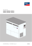
SUNNY CENTRAL 1850-US / 2200-US / 2200 / 2500-EV
MODBUS-SC2xxx-TI-en-13 | Version 1.3
ENGLISH
1 Information on this Document
SMA Solar Technology AG
Legal Provisions
The information contained in these documents is the property of SMA Solar Technology AG. Any publication, whether
in whole or in part, requires prior written approval by SMA Solar Technology AG. Internal reproduction used solely for
the purpose of product evaluation or other proper use is allowed and does not require prior approval.
SMA Factory Warranty
You can download the current warranty conditions from the Internet at www.SMA-Solar.com.
Trademarks
All trademarks are recognized, even if not explicitly identified as such. Missing designations do not mean that a
product or brand is not a registered trademark.
Modbus® is a registered trademark of Schneider Electric and is licensed by the Modbus Organization, Inc.
SMA Solar Technology AG
Sonnenallee 1
34265 Niestetal
Germany
Tel. +49 561 9522-0
Fax +49 561 9522-100
www.SMA.de
E-mail: [email protected]
© 2010 until 2015 SMA Solar Technology AG. All rights reserved.
2
MODBUS-SC2xxx-TI-en-13
Technical Information
SMA Solar Technology AG
1 Information on this Document
Table of Contents
1
2
3
Information on this Document ..................................................................................................... 5
1.1
Validity.................................................................................................................................................................. 5
1.2
Target Group ....................................................................................................................................................... 5
1.3
Additional Information ......................................................................................................................................... 5
1.4
Symbols ................................................................................................................................................................ 5
1.5
Typographies ....................................................................................................................................................... 6
1.6
Nomenclature ...................................................................................................................................................... 6
1.7
Terms and Abbreviations ..................................................................................................................................... 6
Security ........................................................................................................................................ 8
2.1
Intended Use ........................................................................................................................................................ 8
2.2
Information on Data Security .............................................................................................................................. 8
Product Description ..................................................................................................................... 9
3.1
Modbus Protocol ................................................................................................................................................. 9
3.2
SMA Modbus Profile ........................................................................................................................................... 9
3.3
User-Defined Modbus Profile ............................................................................................................................ 10
3.4
SMA Modbus Master Profile ............................................................................................................................ 10
3.5
PV System Topology .......................................................................................................................................... 10
3.6
Addressing and Data Transmission in the Modbus Protocol ........................................................................... 10
3.6.1
Unit IDs .......................................................................................................................................................................... 10
3.6.2
Assignment of the Modbus Register to Unit IDs....................................................................................................... 11
3.6.3
File Formats Used ......................................................................................................................................................... 11
3.6.4
Modbus Register Address, Register Width and Data Block .................................................................................. 11
3.6.5
Address Range for Modbus Register ........................................................................................................................ 11
3.6.6
Data Transmission ........................................................................................................................................................ 11
3.7
Address Types .................................................................................................................................................... 12
3.8
Reading and Writing Data in the Modbus Protocol ........................................................................................ 12
3.9
SMA Data Types ............................................................................................................................................... 13
3.9.1
Data Types .................................................................................................................................................................... 13
3.9.2
16-Bit Integer Values ................................................................................................................................................... 13
3.9.3
32-Bit Integer Values ................................................................................................................................................... 13
3.10 SMA Data Formats ............................................................................................................................................ 14
4
Configuration ............................................................................................................................ 16
4.1
Detection of SMA Modbus Devices and Allocation of Unit IDs...................................................................... 16
4.2
Importing the Modbus Profile File of External Devices .................................................................................... 16
4.3
Exporting the Profile File .................................................................................................................................... 16
4.4
Deleting the Profile File ...................................................................................................................................... 16
Technical Information
MODBUS-SC2xxx-TI-en-13
3
1 Information on this Document
5
SMA Modbus Profile – Assignment Tables ............................................................................... 17
5.1
Information on the Assignment Tables.............................................................................................................. 17
5.2
PV System Parameters (Unit ID = 2) ................................................................................................................. 18
5.3
Inverter Parameter (Unit ID = 3) ....................................................................................................................... 19
5.4
6
7
SMA Solar Technology AG
5.3.1
Holding Parameters ...................................................................................................................................................... 19
5.3.2
Input Register .................................................................................................................................................................21
Zone Monitoring Parameter (Unit ID = 32 and 33) ....................................................................................... 26
Modbus Profiles for External Devices ....................................................................................... 27
6.1
Structure of the XML File for the Modbus Device Profile ................................................................................. 27
6.2
Moxa ioLogik E1240-T – Assignment Table ................................................................................................... 29
6.3
Moxa ioLogik E1242-T – Assignment Table ................................................................................................... 29
6.4
Moxa ioLogik E1260-T – Assignment Table ................................................................................................... 30
User-Defined Modbus Profile .................................................................................................... 31
7.1
Structure of the XML File for the User-Defined Modbus Profile ....................................................................... 31
8
Troubleshooting ......................................................................................................................... 33
9
Technical Data............................................................................................................................ 34
9.1
Supported SMA Devices................................................................................................................................... 34
9.2
Supported Modbus Devices from Other Manufacturers................................................................................. 34
9.3
Modbus Communication Ports.......................................................................................................................... 34
9.4
Reaction time ..................................................................................................................................................... 35
9.5
Interval of the Data Request and Number of Values....................................................................................... 35
10 Contact ....................................................................................................................................... 36
4
MODBUS-SC2xxx-TI-en-13
Technical Information
SMA Solar Technology AG
1 Information on this Document
1 Information on this Document
1.1 Validity
This document is valid for the following device types from firmware version 1.0:
•
•
•
•
Sunny Central 1850-US (SC-1850-US)
Sunny Central 2200-US (SC-2200-US)
Sunny Central 2200 (SC-2200)
Sunny Central 2500-EV (SC-2500-EV)
It describes the variant of the communication protocol "Modbus® Application Protocol" implemented by SMA and also
the corresponding parameters, measured values and data exchange formats.
This document does not contain any information on software which can communicate with the Modbus interface (see
the software manufacturer's manual).
1.2 Target Group
This document is intended for qualified persons. The activities described in this document are to be performed by
qualified persons only. Qualified persons must have the following skills:
•
•
•
•
•
Knowledge of IP-based network protocols
Knowledge of installation and configuration of IT systems
Knowledge of how SMA inverters work and are operated
Training in how to deal with dangers and risks associated with operating electrical devices and systems
Knowledge of and compliance with this document
1.3 Additional Information
SMA Documents
Additional information is available at www.SMA-Solar.com:
Additional Documents
Document title
Source
Service Name and Transport Protocol Port Number
Registry
http://www.iana.org/assignments/service-names-portnumbers/service-names-port-numbers.xml
Modbus Application Protocol Specification
http://www.modbus.org/specs.php
1.4 Symbols
Symbol
Explanation
Information that is important for a specific topic or goal, but is not safety-relevant
◻
Indicates a requirement for meeting a specific goal
☑
Desired result
✖
A problem that might occur.
Technical Information
MODBUS-SC2xxx-TI-en-13
5
SMA Solar Technology AG
1 Information on this Document
1.5 Typographies
Typography
Usage
Example
bold
File names
Select Settings.
Elements to be selected
Read off the configured port in the field
Port.
Elements on a user interface
Enter the value 502 in the field Port.
Elements to be entered
Parameters
>
Connects several elements to be selected
Select Settings > Port.
[Button/Key]
Button or key to be selected or pressed
Select [Next].
[Source]
Data channel name
Reading of the system time (UTC)
[SerTm].
1.6 Nomenclature
Complete Designation
Designation in this Document
SMA Modbus Master Profile
Modbus master profile
Sunny Central 1850-US
Inverter
Sunny Central 2200-US
Sunny Central 2200
Sunny Central 2500-EV
1.7 Terms and Abbreviations
6
Term/abbreviation
Designation
Explanation
Attribute value
-
Changeable content of an XML attribute, e.g.
attribute="My content".
CT
Current measuring unit
Hardware for string-current monitoring
DWORD
-
Data with a width of 32 bits, as per IEC 61131-3
Device ID
-
Numerical value that identifies a certain SMA device
type, e.g. 102 = SMA Power Plant Controller.
GFDI
Ground-Fault Detection and
Interruption
Detection of the grounding error and subsequent
interruption of the electric circuit.
Hex
-
Hexadecimal number
IP
Internet protocol
Network protocol for connections via the Internet
MPP
Maximum Power Point
Maximum power point
MODBUS-SC2xxx-TI-en-13
Technical Information
SMA Solar Technology AG
1 Information on this Document
Term/abbreviation
Designation
Explanation
NaN
Not a Number
No valid value is available.
PMAX
Active power, maximum value
The device can generate active power up to this limit.
Source register
-
Modbus register that is assigned to a different
Modbus address (destination register).
RO
Read Only
Value can only be read
RW
Read/Write
Value can be read and written
SCADA
Supervisory Control and Data
Acquisition
Control center software; in this document SCADA is
used as an example of a Modbus master system.
UTC
Coordinated Universal Time
Universal Time Coordinated
VPN
Virtual Private Network
VPN is used to establish a connection from one private
computer network to another. The point of connection
is established on both sides by a VPN gateway. In
each case, the VPN gateway may be a computer or a
router. The connection itself is described as a VPN
tunnel. A secured data stream runs via the tunnel from
one network to the other, providing VPN nodes from
one network with access to services and devices of the
other network.
WO
Write-only value
Value can only be written
WORD
-
Data with a width of 16 bits, as per IEC 61131-3
Destination register
-
Modbus register to which a different Modbus address
(source register) is assigned. The destination register is
used instead of the source register for further data
processing.
Technical Information
MODBUS-SC2xxx-TI-en-13
7
SMA Solar Technology AG
2 Security
2 Security
2.1 Intended Use
The Modbus interface of the inverter is designed for industrial use and has the following tasks:
• Remote control of the grid management services of a PV system.
• Remote-controlled querying of the measured values of a PV system.
• Remote-controlled changing of the parameters of a PV system.
The Modbus interface can be accessed via the LAN port of the inverter and it can be used via the protocol Modbus
TCP and by the protocol Modbus UDP.
The enclosed documentation is an integral part of this product. You must read and observe the documentation and
keep it in a convenient place for future reference.
2.2 Information on Data Security
Data security in Ethernet networks
You can connect the inverter to the Internet. When connecting to the Internet, there is a risk that unauthorized
users can access and manipulate the data of your system.
• Take appropriate protective measures, e.g.:
- Set up a firewall
- Close unnecessary network ports
- Only enable remote access via VPN tunnel
- Do not set up port forwarding at the Modbus port in use
8
MODBUS-SC2xxx-TI-en-13
Technical Information
SMA Solar Technology AG
3 Product Description
3 Product Description
3.1 Modbus Protocol
The Modbus Application Protocol is an industrial communication protocol that is currently used in the solar sector
mainly for system communication in PV power plants. The Modbus protocol is based on a master/slave architecture.
The Modbus protocol has been developed for reading data from or writing data to clearly defined data areas.
The Modbus specification does not prescribe what data is within which data area. The data areas must be defined
device-specifically in Modbus profiles. With knowledge of the device-specific Modbus profile, a Modbus master
(e.g. a SCADA system) can access the data of a Modbus slave (e.g. communication interface of the inverter).
The special Modbus profile for SMA devices is the SMA Modbus profile.
3.2 SMA Modbus Profile
The SMA Modbus profile contains definitions for selected SMA devices. A reduction of the available data on SMA
devices was carried out for the definition and this was then assigned to the corresponding Modbus registers. The SMA
Modbus profile contains, for example, the total and daily energy, current power, voltage and current levels. The
assignment between SMA device data and Modbus addresses is split into ranges in the SMA Modbus profile and
these can be addressed via unit IDs (see Section 3.6 "Addressing and Data Transmission in the Modbus Protocol",
page 10).
To enable access to the data of an SMA device, a special gateway is required, which is provided via the
communication interface of the inverter.
Technical Information
MODBUS-SC2xxx-TI-en-13
9
SMA Solar Technology AG
3 Product Description
3.3 User-Defined Modbus Profile
The user-defined Modbus profile enables you to reassign Modbus addresses of the SMA Modbus profile.
One advantage of reassigning Modbus addresses can be that the measured values and parameters which are
relevant for a specific purpose, can be applied to consecutive Modbus addresses. These addresses can then be read
or placed in a single data block.
3.4 SMA Modbus Master Profile
The SMA Modbus master profile is an extension of the Modbus interface, which is used to access Modbus-capable
slave devices of other providers. Each external Modbus device has a separate profile (*.mmp) and is managed as a
separate device in the inverter. The external devices can be accessed under the unit IDs = 16 to 31 via the Modbus
slave in the inverter.
3.5 PV System Topology
The SMA Modbus profile was developed for a hierarchical PV system structure. In this structure the inverter has a
communication interface that is equipped with a Modbus TCP/IP and Modbus UDP interface. All other Modbuscapable devices are subordinate to the inverter.
From the perspective of the Modbus protocol, the inverter represents a Modbus slave that provides a gateway to the
Modbus-capable devices. These devices can only be addressed via the gateway of the inverter by unit ID.
3.6 Addressing and Data Transmission in the Modbus Protocol
3.6.1
Unit IDs
The unit ID is a superordinate addressing type in the Modbus protocol. The SMA Modbus protocol has 247 unit IDs,
of which 245 can be assigned to individual devices. If a unit ID is assigned to a device, then the parameters and
measured values of this device can be accessed.
The following table shows an overview of the unit IDs in the SMA Modbus profile: Individual unit IDs and unit-ID
ranges are reserved and are not used with automatic system detection. With manual detection, however, these can be
used:
Unit ID
Explanation
2
This unit ID is reserved for the PV system parameters.
3
This unit ID is reserved for the inverter.
4 to 15
Reserved
16 to 31
External devices. The last character of the IP address of the external device corresponds to the
assigned unit ID.
32
Left DC module for zone monitoring
33
Right DC module for zone monitoring
34 to 99
Reserved
100
User-defined modbus profile
101
Reserved
102
SMA Power Plant Controller
103 to 247
Reserved
10
MODBUS-SC2xxx-TI-en-13
Technical Information
SMA Solar Technology AG
3 Product Description
Unit ID
Explanation
255
Devices that are assigned to this unit ID cannot be addressed. You must assign unit IDs from the
range 3 to 247 to these devices (see Section Fehler! Verweisquelle konnte nicht gefunden
werden. "Fehler! Verweisquelle konnte nicht gefunden werden.", page Fehler!
Textmarke nicht definiert.).
3.6.2
Assignment of the Modbus Register to Unit IDs
The assignment of the parameters and measured values of the SMA devices to Modbus register addresses is achieved
using assignment tables and is also shown in this document (see Section 5 "SMA Modbus Profile – Assignment
Tables", page 17).
In the assignment table "PV System Parameters (unit ID = 2)", parameters and measured values of the inverter and of
the PV system are saved.
In the assignment table "Inverter (unit ID = 3)", the parameters and measured values used in the inverter are saved.
In the assignment tables "External devices (unit ID = 16 to 31)", the channels used for the various external devices are
saved.
3.6.3
File Formats Used
The Modbus protocols are saved in XML format. For easier assignment, the profiles of the various devices have
different file extensions.
Extension
Explanation
*.kmp
Modbus profile of the inverter
*.vdp
User-defined modbus profile
*.mmp
Modbus profile of external devices
3.6.4
Modbus Register Address, Register Width and Data Block
3.6.5
Address Range for Modbus Register
3.6.6
Data Transmission
A Modbus register is 16 bits wide. For wider data types, connected Modbus registers are used and considered as
data blocks. The number of connected Modbus registers is indicated in the assignment tables. The address of the first
Modbus register in the data block is the start address of the data block. In addition, larger data blocks can be formed.
For addressing Modbus registers, the address range 0 to 0xFFFF is available with 65536 addresses.
In accordance with the Modbus specification, only a specific volume of data can be transported in a single data
transmission in a simple Protocol Data Unit (PDU). The data also contains function-dependent parameters such as the
function code, start address or number of Modbus registers to be transmitted. The amount of data depends on the
Modbus command used and has to be taken into account during data transmission. You can find the number of
possible Modbus registers per command in Section 3.8.
With data storage in the Motorola format "Big Endian", data transmission begins with the high byte and then the low
byte of the Modbus register.
Technical Information
MODBUS-SC2xxx-TI-en-13
11
SMA Solar Technology AG
3 Product Description
3.7 Address Types
The individual Modbus registers can be addressed with different data.
Address type
Explanation
Modbus function code
Coil
One bit, which can be read and written, is
set, e.g. for digital signals.
FC 01 (0x01) – Read Coils
FC 05 (0x05) – Write single coil
Discrete
One bit, which can be read and written, is
set, e.g. for digital signals.
FC 02 (0x02) – Read discrete inputs
Input
The addressed registers contain measured
values and can only be read (RO).
FC 04 (0x04) – Read Input registers
Holding
The addressed registers contain
parameters and can be read and written
(RW).
FC 03 (0x03) – Read holding registers
FC 15 (0x0F) – Write multiple coil
FC 06 (0x06) – Write single holding register
FC 16 (0x10) – Write multiple holding registers
3.8 Reading and Writing Data in the Modbus Protocol
The Modbus interface can be used via the protocol Modbus TCP and by the protocol Modbus UDP. Using Modbus
TCP enables read- and write access (RW) and using Modbus UDP enables only write access (WO) to the Modbus
register.
The following Modbus commands are supported by the implemented Modbus interface:
Modbus command
Modbus function code
Data volume (number of registers) 1
Read coils2
FC 01 (0x01)
1 to 2000
Read Discrete Input
FC 02 (0x02)
1 to 2000
Read Holding Registers
FC 03 (0x03)
1 to 123
Read Input Registers
FC 04 (0x04)
1 to 125
Write Single Coil
FC 05 (0x05)
1
Write Single Holding Register
FC 06 (0x06)
1
Write Multiple Coil
FC 15 (0x0F)
1 to 1968
Write Multiple Registers
FC 16 (0x10)
1 to 123
Reading or writing a single Modbus register
If a Modbus register is accessed, which is not contained in the Modbus profile, or if a Modbus command is incorrect,
a Modbus exception is generated. Modbus exceptions are also generated when write access occurs on a read-only
Modbus register or read access occurs on a write-only Modbus register.
Reading or writing of data blocks
To prevent inconsistencies, data blocks of associated registers or register ranges must be read or written consecutively.
1
2
Number of Modbus registers transferable as data block per command (16 bit)
Not available for the SMA Modbus master profile.
12
MODBUS-SC2xxx-TI-en-13
Technical Information
SMA Solar Technology AG
3 Product Description
Writing multiple Modbus registers as a data block
If multiple registers are written in the data block (Modbus command 0x10) and an error occurs when writing, the next
register in the data block is used to proceed. If some data is dependent on other data, or if some data is mutually
exclusive, the data is only processed if the entire data block is valid. Otherwise the entire data block is discarded.
In the event of an error, a Modbus exception will be generated.
Reading multiple Modbus registers as a data block
If a data block is read and if at least one register defined in the Modbus profile can be determined in its data range,
an answer is returned. If none of the Modbus registers are defined in the data range of a data block in the Modbus
profile, the query is invalid and a Modbus exception is generated.
Modbus exceptions
For Modbus exceptions, see "Modbus Application Protocol Specification" at http://www.modbus.org/specs.php.
3.9 SMA Data Types
3.9.1
Data Types
The following table shows the data types used in the SMA Modbus profile. The SMA data types are listed in the
assignment tables in the Type column. They describe the data widths of the assigned values:
Type
Description
U16
A word (16-bit/WORD) in the local processor format
S16
A signed word (16-bit/WORD) in local processor format
U32
A double word (32 bit/DWORD) in the local processor format
S32
A signed double word (32 bit/DWORD) in the local processor format
3.9.2
16-Bit Integer Values
16-bit integers are stored in a Modbus register.
Modbus register
1
Byte
0
1
Bits
8 to 15
0 to 7
3.9.3
32-Bit Integer Values
32-bit integers are stored in two Modbus registers.
Modbus register
1
Byte
0
1
2
3
Bits
24 to 31
16 to 23
8 to 15
0 to 7
Technical Information
2
MODBUS-SC2xxx-TI-en-13
13
SMA Solar Technology AG
3 Product Description
3.10 SMA Data Formats
The following SMA data formats describe how SMA data is to be interpreted. The data formats are used, for example,
for the display of data or for its further processing. The SMA data formats are listed in the Format column of the
assignment tables.
Format
Explanation
Duration
Duration
Time in seconds, in minutes or in hours, depending on the Modbus register.
Date/time
DT
Date/time, in accordance with country setting. Transmission as UTC (seconds since
1970-01-01).
Factor 1
FIX0
Decimal number, commercially rounded, no decimal place.
Scaling factor to define the decimal places (up to 8)
FIX1
to FIX8
Decimal number, commercially rounded, number of decimal places in accordance
with the number (FIX2 corresponds to a decimal number with two decimal places)
Coded numerical values. Display of settings in abbreviations, e.g. for operating
states or selected procedures for setpoint. Here it is only possible to select one
numerical value in each case.
ENUM
The breakdown of the possible codes can be found directly under the designation
of the Modbus register in the SMA Modbus profile – assignment tables.
ENUM_FLAG
Coded numerical values. Display of settings in abbreviations, e.g. for operating
states or selected procedures for setpoint. Here it is possible to select multiple
numerical values.
VERSION
Firmware version (see "Firmware version extract" below)
TIME_DDMMYY
Display as date, e.g "020913" for September 2, 2013
TIME_YYYYMMDD
Display as date, e.g "20130902" for September 2, 2013
TIME_HHMMSS
Display as time, e.g. "134725" for 13:47:25
TIME_YYYYMMDDHHMMSS
Display as date and time, e.g "20130902134725" for September 2, 2013,
13:47:25
BITMASK
Assignment of meaning of the individual bits of the register
PLAINSTRING
Display as text
ARRAY
Display as text
IPV4
Display as IP V4 address, e.g. "192.168.0.5"
IPV4_ADDR_LIST
Display as list of IP V4 addresses
IPV4_ADDR_MASK
Display as IP V4 address and netmask
IPV6
Display as IP V6 address, e.g. "2001:0db8:85a3:08d3:1319:8a2e:0370:7344"
MAC
Display as MAC address, e.g. "12-34-56-78-9A-BC"
DURATION
Display as duration, e.g. days h:min:sec or h:min:sec
ACTION
Display as visual button
14
MODBUS-SC2xxx-TI-en-13
Technical Information
SMA Solar Technology AG
3 Product Description
Format
Explanation
ACTION_CONFIRMED
Display as visual button with option to confirm
BOOL
Display as checkbox or any other boolean display
Abstract firmware version, format "FW"
Four values are extracted from the delivered DWORD. The values Major and Minor are contained, BCD-coded, in
bytes 1 and 2. Byte 3 contains the Build value (not BCD-coded).
Byte 4 contains the Release Type value according to the following table:
Release type
Release-type coding
Explanation
3
B
Beta release
4
R
Release
5
S
Special release
>5
As number
No special interpretation
Example:
Firmware version of the product:
Values from DWORD:
Technical Information
1.5.10.R
Major: 1, Minor: 5, Build: 10, Release type: 4
(Hex: 0x1 0x5 0xA 0x4)
MODBUS-SC2xxx-TI-en-13
15
4 Configuration
SMA Solar Technology AG
4 Configuration
4.1 Detection of SMA Modbus Devices and Allocation of Unit IDs
With a new PV power plant, the Modbus is activated on commissioning and the Modbus-capable devices are
detected on commissioning. The Modbus-capable SMA devices log in to the inverter independently and the inverter
assigns them a unit ID.
If new SMA devices are added to the system or if devices must be replaced, the new devices are also detected
automatically.
4.2 Importing the Modbus Profile File of External Devices
External Modbus devices can be connected to the inverter. In order to be able to access these devices via the Modbus
protocol also, the external Modbus devices must be detected in the system.
Procedure:
1. Open Modbus profile of the external device in a UTF-8-capable editor (e.g. Notepad++).
2. In the Modbus profile, enter the IP address under which the device can be accessed.
3. Save change. Give the file a unique name. If multiple files of the same name are used, during an import the
existing file will be overwritten in each case by the imported file.
4. Log in to the user interface of the inverter as installer (see the inverter user manual).
5. Import the changed Modbus profile (see inverter user manual). Here, select Modbus Profiles from the list of
available types. A unit ID is assigned to the device automatically.
4.3 Exporting the Profile File
1. Log in to the user interface of the inverter as installer (see the inverter user manual).
2. In the main navigation, select Export (see inverter user manual).
3. Select Modbus profiles from the list of available types.
4. Select the Modbus profile to be exported.
5. If the profile file is to be saved to an external storage medium that is present in the inverter, select the
[Copy file to external device] button.
If the profile file is to be saved on the computer, select the [Download] button.
6. Choose a storage location for the profile file and save it.
4.4 Deleting the Profile File
1. Log in to the user interface of the inverter as installer (see the inverter user manual).
2. In the main navigation, select Export (see inverter user manual).
3. Select Modbus profiles from the list of available types.
4. Select the Modbus profile to be deleted.
5. Select the button [Delete files].
16
MODBUS-SC2xxx-TI-en-13
Technical Information
SMA Solar Technology AG
5 SMA Modbus Profile – Assignment Tables
5 SMA Modbus Profile – Assignment Tables
5.1 Information on the Assignment Tables
The following subsections are sorted by unit ID. Each contains a table of the Modbus addresses which can be
accessed using this unit ID. The tables present the following information:
Information
Explanation
ADR (DEC)
Decimal Modbus address (see Section 3.6 and onwards)
Channel name
Name of the channel
Explanation
Short description of the data channel of the Modbus register
CNT (WORD)
Number of occupied Modbus registers (see Section 3.6 and onwards)
Unique ID
Assignment to the channels in the inverter
Data Type
Data type, e.g. U32 = 32 bits without prefix (see Section 3.6).
Data Format
Data format of the saved value, e.g. DT = date, FIXn = output with n decimal
places, TEMP = output as temperature (see Section 3.10)
Access
Access type for Modbus TCP (see Section 3.8 "Reading and Writing Data in
the Modbus Protocol", page 12):
RO: Read only
RW: Read and write
If an access type is not supported, a Modbus exception will be generated.
Scaling
Specification of scaling factor with which the data must be converted
Offset
Specification of offset with which the data must be converted
Unit
Specification of the unit in which the data is specified
Technical Information
MODBUS-SC2xxx-TI-en-13
17
SMA Solar Technology AG
5 SMA Modbus Profile – Assignment Tables
5.2 PV System Parameters (Unit ID = 2)
Format
Access
Version number of the SMA Modbus profile
2
U32
RAW
RO
2
Device ID of the communication interface
2
U32
RAW
RO
6
Modbus data change: Meter value is increased on each
access.
2
U32
RAW
RO
18
MODBUS-SC2xxx-TI-en-13
Type
Data
0
CNT
Description/number code
(DEC)
Register
(WORD)
In the following table, you can find the PV system parameters that you can access using unit ID = 2 and function code
0x04. The PV system parameters represent measured values and parameters of the inverter and also PV system
devices that are connected via the Modbus protocol. Parameters such as time settings are transferred by the inverter to
the devices of the PV system and there, depending on the device type, processed further. Measured values such as
energy meter values are queried by the devices and made available as accumulated values:
Technical Information
SMA Solar Technology AG
5 SMA Modbus Profile – Assignment Tables
5.3 Inverter Parameter (Unit ID = 3)
5.3.1
Holding Parameters
Unit
Data Format
Offset
Scaling
Data Type
Unique ID
Modbus register
number
In the following table, you can find the measured values supported by the inverter, which you can access under unit
ID = 3 and function code 0x03, 0x06 and 0x10 (see Section 3.6.1 "Unit IDs", page 10).
Channel name
Explanation
0
InvOpMod
Operating state of the inverter,
setpoint
329
S32
1
0
ENUM
-
2
RemRdy
Put inverter into operation or standby
331
S32
1
0
ENUM
-
4
GriMng.VArMod
Utility grid system services: Selection of
procedure for setpoint for reactive
power
6080
S32
1
0
ENUM
-
6
GriMng.WMod
Utility grid system services: Selection of
procedure for setpoint for active
power
6078
S32
1
0
ENUM
-
8
ErrClr
Acknowledgment of the present error
733
S32
1
0
ENUM
-
10
VADrtPriMod
Prioritizing of control of derating
730
S32
1
0
ENUM
-
12
WGraMod
Activates the active power gradient
725
S32
1
0
ENUM
-
14
WGra
Active power set point
726
S32
1000
0
FIX3
##
16
VArGraMod
Activates the reactive power gradient
727
S32
1
0
ENUM
-
18
VArGra
Reactive power setpoint
728
S32
1000
0
FIX3
##
Technical Information
MODBUS-SC2xxx-TI-en-13
19
SMA Solar Technology AG
5 SMA Modbus Profile – Assignment Tables
Related ENUM Codes
2
4
6
8
10
InvOpMod
329
RW
RemRdy
GriMng.VArMod
GriMng.WMod
ErrClr
VADrtPriMod
12
WGraMod
16
VArGraMod
20
331
6080
6078
733
730
RW
RW
RW
RW
RW
725
727
MODBUS-SC2xxx-TI-en-13
RW
Return code
Access
0
Channel
Unique ID
Address
The following table contains number codes which, as function coding in data format ENUM, are frequently used in the
SMA Modbus profile. The column "Related text" contains the corresponding abbreviations.
Related text
973
---
381
Stop
309
Operation
973
---
308
Enabled
303
Disabled
1387
VArCtlAnIn
1388
PFCtlAnIn
1072
VArCtlCom
1075
PFCtlCom
2270
AutoCom
1071
VArCtlMan
1074
PFCtlMan
303
Off
1390
WCtlAnIn
1079
WCtlCom
1077
WCtlMan
303
Off
973
---
26
Ackn
16
VAr
18
W
973
---
308
303
Enable
Disable
Technical Information
SMA Solar Technology AG
5.3.2
5 SMA Modbus Profile – Assignment Tables
Input Register
Channel name
Explanation
Unique ID
Data Type
Scaling
Offset
Data Format
Unit
Modbus register
number
In the following table, you can find the parameters supported by the inverter, which you can access under unit ID = 3
and function code 0x04 (see Section 3.6.1 "Unit IDs", page 10).
0
DcMs.Vol
DC voltage DC plus to DC
minus
597
S32
10
0
FIX1
V
2
DcMs.Amp.Stk1
DC current inverter bridge 1
600
S32
1
0
FIX0
A
4
DcMs.Amp.Stk2
DC current inverter bridge 2
601
S32
1
0
FIX0
A
6
DcMs.Amp.Stk3
DC current inverter bridge 3
602
S32
1
0
FIX0
A
8
DcMs.TotAmp
DC current, total
6146
S32
1
0
FIX0
A
10
DcMs.TotWatt
DC power, total
603
S32
1
0
FIX0
kW
12
InvMs.DclVol.Stk1
DC voltage of the inverter
bridge 1
616
S32
10
0
FIX1
V
14
InvMs.DclVol.Stk2
DC voltage of the inverter
bridge 2
617
S32
10
0
FIX1
V
16
InvMs.DclVol.Stk3
DC voltage of the inverter
bridge 3
618
S32
10
0
FIX1
V
18
InvMs.TotA.PhsA
AC current L1, total
408
S32
1
0
FIX0
A
20
InvMs.TotA.PhsB
AC current L2, total
409
S32
1
0
FIX0
A
22
InvMs.TotA.PhsC
AC current L3, total
410
S32
1
0
FIX0
A
24
InvMs.PF
Power factor (cos phi)
404
S32
10000
0
FIX4
-
26
InvMs.TotVA
Apparent power, total
401
S32
1
0
FIX0
kVA
28
InvMs.TotW
Active power, total
402
S32
1
0
FIX0
kW
30
InvMs.TotVAr
Reactive power, total
403
S32
1
0
FIX0
kVAr
32
GriMs.V.PhsAB
Line-to-line voltage L1-L2, utility
grid
405
S32
10
0
FIX1
V
34
GriMs.V.PhsBC
Line-to-line voltage L2-L3, utility
grid
406
S32
10
0
FIX1
V
36
GriMs.V.PhsCA
Line-to-line voltage L3-L1, utility
grid
407
S32
10
0
FIX1
V
38
GriMs.Hz
Power frequency
607
S32
100
0
FIX2
Hz
40
TmpCab.Acc
Temperature in the AC range
751
S32
10
0
FIX1
°C
Technical Information
MODBUS-SC2xxx-TI-en-13
21
SMA Solar Technology AG
Channel name
Explanation
Unique ID
Data Type
Scaling
Offset
Data Format
Unit
Modbus register
number
5 SMA Modbus Profile – Assignment Tables
42
TmpCab.Dcc
Temperature in the DC range
750
S32
10
0
FIX1
°C
44
TmpCab.Rio
Temperature in the electronics
area
752
S32
10
0
FIX1
°C
46
TmpCab.Max
Temperature in interior,
maximum value
6130
S32
10
0
FIX1
°C
TmpStk.IgbtMax
Temperature of the inverter
bridge (switch), maximum
value
6100
S32
10
0
FIX1
°C
50
TmpStk.PcbMax
Temperature of the inverter
bridge (assembly), maximum
value
6099
S32
10
0
FIX1
°C
52
TmpExl
Outside temperature
759
S32
10
0
FIX1
°C
54
TmpTrf
Temperature of the MV
transformer
6107
S32
10
0
FIX1
°C
56
DcSw1Stt
Switching status of the DC
load-break switch 1
611
S32
1
0
ENUM
-
58
DcSw2Stt
Switching status of the DC
load-break switch 2
721
S32
1
0
ENUM
-
60
DcSw3Stt
Switching status of the DC
load-break switch 3
722
S32
1
0
ENUM
-
62
AcSwStt
Switching status of the AC
circuit breaker
6202
S32
1
0
ENUM
-
66
CapacSwStt
Switching state of the capacitor
contactor
6708
S32
1
0
ENUM
-
68
PrchrgSwStt
Switching status of the precharging contactor
6707
S32
1
0
ENUM
-
70
Cnt.TotFeedTm
Feed-in hours
6779
U32
1
0
FIX0
-
72
Cnt.TotOpTm
Operating hours
6777
U32
1
0
FIX0
-
74
Cnt.TotWatthIn
DC energy drawn, total
7119
S32
100
0
FIX2
MWh
76
Cnt.TotWhOut
AC energy fed in, total
7118
S32
100
0
FIX2
MWh
78
Cnt.WatthIn
DC energy drawn that day
6771
S32
100
0
FIX2
MWh
80
Cnt.WhOut
AC energy fed in that day
6767
S32
100
0
FIX2
MWh
48
22
MODBUS-SC2xxx-TI-en-13
Technical Information
SMA Solar Technology AG
Modbus register
number
Channel name
Explanation
Unique ID
Data Type
Scaling
Offset
Data Format
Unit
5 SMA Modbus Profile – Assignment Tables
82
Cnt.FanCab1Tm
Operating hours of the interior
fan 1
6793
U32
1
0
FIX0
-
84
Cnt.FanCab2Tm
Operating hours of the interior
fan 2
6795
U32
1
0
FIX0
-
86
Cnt.FanStkTm
Operating hours of the inverter
bridge fan
6791
U32
1
0
FIX0
-
88
Cnt.HtCabTm
Operating hours of the internal
heating element
6797
U32
1
0
FIX0
-
90
Cnt.HtLoExlTmpTm
Operating hours of the -40°C
internal heating element
6799
U32
1
0
FIX0
-
92
ErrLcn
Error location of the present
error
6968
U32
1
0
FIX0
-
94
ErrStt
Error status of the inverter
328
S32
1
0
ENUM
-
96
ErrNo
Error number of the present
error
823
U32
1
0
FIX0
-
98
OpStt
Operating state of the inverter
332
S32
1
0
ENUM
-
100
Rio.KeySw
Switch status of the start-stop
key switch
327
S32
1
0
ENUM
-
102
WaitGriTm
Waiting time for grid
connection
614
S32
10
0
FIX1
s
104
DevInf.SerNo
Inverter serial number
6763
U32
1
0
FIX0
-
106
GfdiSwStt
Switching status of the GFDI
6706
S32
1
0
ENUM
-
108
WSpt
Active power, setpoint
320
S32
1
0
FIX0
kW
110
VAMaxSpt
Maximum apparent power,
setpoint
665
S32
10
0
FIX1
kVA
112
VArSpt
Reactive power, setpoint
321
S32
1
0
FIX0
kVAr
114
PFSpt
Power factor cos (phi), setpoint
322
S32
10000
0
FIX4
-
116
TrfPro.Pres
Fast stop hermetic protection,
pressure
7029
S32
1
0
ENUM
-
118
TrfPro.TmpTrp
Fast stop hermetic protection,
temperature
506
S32
1
0
ENUM
-
120
TrfPro.GasOilLev
Hermetic protection, gas fill
level
7170
S32
1
0
ENUM
-
Technical Information
MODBUS-SC2xxx-TI-en-13
23
SMA Solar Technology AG
Channel name
Explanation
Unique ID
Data Type
Scaling
Offset
Data Format
Unit
Modbus register
number
5 SMA Modbus Profile – Assignment Tables
122
TrfPro.TmpWrn
Hermetic pressure, temperature
warning
7168
S32
1
0
ENUM
-
124
TmpStk1.lgbt
Temperature of inverter bridge
1 (switch)
756
S32
10
0
FIX1
°C
126
TmpStk2.lgbt
Temperature of inverter bridge
2 (switch)
757
S32
10
0
FIX1
°C
128
TmpStk3.lgbt
Temperature of inverter bridge
3 (switch)
758
S32
10
0
FIX1
°C
130
TmpStk1.Pcb
Maximum temperature of
inverter bridge 1 (assembly)
753
S32
10
0
FIX1
°C
132
TmpStk2.Pcb
Maximum temperature of
inverter bridge 2 (assembly)
754
S32
10
0
FIX1
°C
134
TmpStk3.Pcb
Maximum temperature of
inverter bridge 3 (assembly)
755
S32
10
0
FIX1
°C
136
Cnt.YstdWhOut
##
7032
S32
100
0
FIX2
MWh
Related ENUM Codes
Channel
Unique ID
Access
56
DcSw1Stt
611
RO
60
DcSw3Stt
722
RO
58
62
66
68
94
24
DcSw2Stt
721
AcSw1Stt
6202
PrchrgSwStt
6707
CapacSwStt
ErrStt
MODBUS-SC2xxx-TI-en-13
6708
328
RO
RO
RO
Return code
Address
The following table contains number codes which, as function coding in data format ENUM, are frequently used in the
SMA Modbus profile. The column "Related text" contains the corresponding abbreviations.
Related text
973
311
51
--Open
Closed
973
---
307
Ok
1392
Error
RO
RO
Technical Information
SMA Solar Technology AG
Unique ID
98
OpStt
332
Return code
Channel
Access
Address
5 SMA Modbus Profile – Assignment Tables
RO
1787
Init
381
Stop
1392
Error
3522
Update
3523
Reset
1394
WaitAC
3524
ConnectAC
1393
WaitDC
3525
ConnectAC
3526
GridFeed
3527
FRT
3528
Standby
3529
QonDemand
3530
RampDown
1469
ShutDown
375
Selftest
973
---
308
On
303
Off
973
---
311
Open
51
Closed
Rio.KeySw
100
327
RO
GfdiSwStt
106
6706
116
TrfPro.Pres
7029
120
TrfPro.GasOilLev
7170
118
122
TrfPro.TmpTrp
TrfPro.TmpWrn
Technical Information
506
7168
RO
RO
973
307
1392
Related text
--Ok
Error
MODBUS-SC2xxx-TI-en-13
25
SMA Solar Technology AG
5 SMA Modbus Profile – Assignment Tables
5.4 Zone Monitoring Parameter (Unit ID = 32 and 33)
Number of available inputs
Input
U16
1
0
FIX0
-
55
DcMs.Amp.01
DC current input 1
Input
S16
10
0
FIX1
A
56
DcMs.Amp.02
DC current input 2
Input
S16
10
0
FIX1
A
57
DcMs.Amp.03
DC current input 3
Input
S16
10
0
FIX1
A
58
DcMs.Amp.04
DC current input 4
Input
S16
10
0
FIX1
A
59
DcMs.Amp.05
DC current input 5
Input
S16
10
0
FIX1
A
60
DcMs.Amp.06
DC current input 6
Input
S16
10
0
FIX1
A
61
DcMs.Amp.07
DC current input 7
Input
S16
10
0
FIX1
A
62
DcMs.Amp.08
DC current input 8
Input
S16
10
0
FIX1
A
63
DcMs.Amp.09
DC current input 9
Input
S16
10
0
FIX1
A
64
DcMs.Amp.10
DC current input 10
Input
S16
10
0
FIX1
A
65
DcMs.Amp.11
DC current input 11
Input
S16
10
0
FIX1
A
66
DcMs.Amp.12
DC current input 12
Input
S16
10
0
FIX1
A
67
DcMs.Amp.13
DC current input 13
Input
S16
10
0
FIX1
A
68
DcMs.Amp.14
DC current input 14
Input
S16
10
0
FIX1
A
69
DcMs.Amp.15
DC current input 15
Input
S16
10
0
FIX1
A
70
DcMs.Amp.16
DC current input 16
Input
S16
10
0
FIX1
A
26
MODBUS-SC2xxx-TI-en-13
Unit
Offset
DcMs.AmpMsCnt
Data Format
Scaling
11
Data Type
Explanation
Address type
Channel name
Unique ID
Modbus register
number
In the following table, you can find the measured values and parameters supported by zone monitoring, which you
can access under unit ID = 32 and 33 (see Section 3.6.1 "Unit IDs", page 10).
Technical Information
SMA Solar Technology AG
6 Modbus Profiles for External Devices
6 Modbus Profiles for External Devices
With the Modbus profile, Modbus devices (slaves) of other manufacturers can be integrated in the inverter.
The Modbus device profile acts like a Modbus device of SMA Solar Technology AG.
The Modbus master profile is an XML file in which, for each channel tag, one Modbus register of a slave device is
allocated to any Modbus address. For the assignments, an address range from 0 to 65535 is available in each case.
Currently, various Moxa IO modules from the ioLogik series are supported (see Section 9.2 "Unit IDs", page 34).
The relevant XML templates can be acquired, adapted and imported from SMA Solar Technology AG.
The stored assignments are requested at regular intervals (default: 1000 ms).
Currently, the Modbus device profile contains register assignments for the following devices:
•
•
•
"Moxa ioLogik E1240-T" (see Section 6.2 "Moxa ioLogik E1240-T – Assignment Table", page 29)
"Moxa ioLogik E1242-T" (see Section 6.3 "Moxa ioLogik E1242-T – Assignment Table", page 29)
"Moxa ioLogik E1260-T" (see Section 6.4 "Moxa ioLogik E1260-T – Assignment Table", page 30).
6.1 Structure of the XML File for the Modbus Device Profile
The Modbus device profile is created in the file *.mmp .
The basic structure of the XML file is as follows:
<?xml version="1.0" encoding="UTF-8"?>
<ModbusMasterProfile>
<ProfileVersion version=”514”>
<ModbusDevices>
<Device name="aaa" type="bbb" description="ccc">
<Modbus ipaddress="192.168.100.16" port="502" unitid="16"/>
<Mapping>
<Channel />
…
</Mapping>
</Device>
</ModbusDevices>
</ModbusMasterProfile>
Legend for XML tags and attributes:
The term "source register" in the following table stands for a specific Modbus register of the slave device, which is used
as source for the assignment.
XML tag / attribute
Explanation
<ModbusMasterProfile>
</ModbusMasterProfile>
The Modbus device profile is defined within this XML structure.
<ModbusDevices>
The Modbus device profile is defined within this XML structure.
Device name="aaa"
Here you can assign any term for the device name. The XML template contains an entry
appropriate for the device.
type="bbb"
Here you can assign any term for the device type. The XML template contains an entry
appropriate for the device.
</ModbusDevices>
Technical Information
MODBUS-SC2xxx-TI-en-13
27
6 Modbus Profiles for External Devices
SMA Solar Technology AG
XML tag / attribute
Explanation
description="ccc"
Here you can assign any term for the use. The XML template contains an entry
appropriate for the device.
Modbus ipaddress
="192.168.100.16"
IPv4 address of the slave device. The IP addresses can be assigned in the range from
192.168.100.16 to 192.168.100.31.
port="502"
Modbus communication port of the slave device. The default setting is 502.
unitid="0"
Unit ID (8 bit) of the slave device (see manufacturer datasheet).
<Mapping>
Within this XML structure, the profiles of the different channels are defined.
</ Mapping >
<Channel />
Within every channel tag, one source register of a slave device is assigned to the
Modbus profile.
The following attributes can be assigned to each channel:
XML attribute
Explanation
name="ddd"
Here you can assign any name to the assignment.
tagid_index
Numerical index as suffix to the name of a channel (e.g. AIn1, AIn2, AIn3). If no index
is required, then this attribute can remain empty.
source
Decimal address of the source register (see attribute "destination"). You can find
possible "source" values in the datasheet of the manufacturer of each Modbus device.
destination
Decimal address (0 to 65535) of the Modbus register to which the value is assigned
(destination register). Observe the length (in WORD) of the source register (see
attribute "size").
datatype
Data format of the saved value, e.g. DT = date, FIXn = output with n decimal places,
TEMP = output as temperature (see Section 3.10)
type
Type of the register, e.g. Holding (see Section 0)
size
Length of the source register (in WORD) (1 = 16 or 2 = 32), depending on register
type.
Holding or input register: 1, 2
Coil: 1
Depending on the length of the source register (1 or 2 WORD), the target addresses
should be set for the status register and quality register following the "destination"
register, e.g. destination = 1000 (size = 2), status = 1002, quality = 1003 + 1004,
ensuring that they do not overlap with the subsequent registers.
swap
Definition of sequence of the Modbus register for data transmission
0 - first the high byte and then the low byte of the Modbus register
1 - first the low byte and then the high byte of the Modbus register
scale
Specification of scaling factor with which the data must be converted
offset
Signed offset value which is to be added to the source data. The default setting is 0.
min
Lower value of the permitted range for valid values of the channel
max
Upper value of the permitted range for valid values of the channel
28
MODBUS-SC2xxx-TI-en-13
Technical Information
SMA Solar Technology AG
6 Modbus Profiles for External Devices
XML attribute
Explanation
representation
Data format of the saved value, e.g. DT = date, FIXn = output with n decimal places,
TEMP = output as temperature (see Section 3.10)
unit
Displayed unit of the channel
Modbus exceptions
For Modbus exceptions, see "Modbus Application Protocol Specification" at
http://www.modbus.org/specs.php.
6.2 Moxa ioLogik E1240-T – Assignment Table
In this section you will find a table with an overview of the Modbus registers that are saved in the Modbus master
profile for the "Moxa ioLogik E1240-T". In accordance with the XML structure, each line of the table shows the attribute
values of a Modbus register assignment. The attribute values in the columns "source", "type" and "size" correspond to
the standard values of the "Moxa ioLogik E1240-T".
Changed settings of the Moxa ioLogik E1240-T
If you change the settings (e.g. ip, description, etc.) of the "Moxa ioLogik E1240-T", you also have to change
the attribute values of the Modbus master profile.
0
-32768
32768
unit
1
representation
0
max
1
min
datatype
S16
offset
Input
scale
0 to 65535
type
destination
0 to
65535
swap
1
to
n
size (WORD)
"AIn1" to "AIn8"
source
Channel/name
tagid_index
The following channels are defined in the profile file:
FIX2
A
6.3 Moxa ioLogik E1242-T – Assignment Table
In this section you will find a table with an overview of the Modbus registers that are saved in the Modbus master
profile for the "Moxa ioLogik E1242-T". In accordance with the XML structure, each line of the table shows the attribute
values of a Modbus register assignment. The attribute values in the columns "source", "type" and "size" correspond to
the standard values of the "Moxa ioLogik E1242-T".
Changed settings of the Moxa ioLogik E1242-T
If you change the settings (e.g. ip, description, etc.) of the "Moxa ioLogik E1242-T", you also have to change
the attribute values of the Modbus device profile.
<Channel />
Within every channel tag, one source register of a slave device is assigned to the
Modbus profile.
The register assignments for the individual devices can be found in the following
sections.
Technical Information
MODBUS-SC2xxx-TI-en-13
29
SMA Solar Technology AG
6 Modbus Profiles for External Devices
size (WORD)
swap
scale
offset
max
representation
unit
512
to
515
0 to
7
Input
U16
1
0
1
0
0
65535
FIX0
-
AIn_Float
1 to 4
520
to
526
12
to
15
Input
F32
2
0
1
0
4.0
20.0
FIX3
mA
32
0
Holding
U16
1
0
1
0
0
65535
FIX0
-
source
DOAll
min
datatype
1 to 4
type
AIn_Digit
Channel/
destination
name
tagid_index
The following channels are defined in the profile file:
DigIn
1 to 8
0 to 7
4 to
11
Discrete
Bool
1
0
1
0
0
1
FIX0
-
DigOut
1 to 4
0 to 3
1 to
4
Coil
Bool
1
0
1
0
0
1
FIX0
-
6.4 Moxa ioLogik E1260-T – Assignment Table
In this section you will find a table with an overview of the Modbus registers that are saved in the Modbus master
profile for the "Moxa ioLogik E1260-T". In accordance with the XML structure, each line of the table shows the attribute
values of a Modbus register assignment. The attribute values in the columns "source", "type" and "size" correspond to
the standard values of the "Moxa ioLogik E1260-T".
Changed settings of the Moxa ioLogik E1260-T
If you change the settings (e.g. ip, description, etc.) of the "Moxa ioLogik E1260-T", you also have to
change the attribute values of the Modbus master profile.
XML tag or attribute
Explanation
<ModbusMasterProfile>
</ModbusMasterProfile>
The Modbus device profile is defined within this XML structure.
30
MODBUS-SC2xxx-TI-en-13
U16
0
0
65535
FIX0
unit
1
representation
0
max
1
min
offset
Input
datatype
type
destination
0 to 5
scale
1536
to
1541
swap
1
to
6
size (WORD)
Temperature
source
Channel/name
tagid_index
The following channels are defined in the profile file:
°C
Technical Information
SMA Solar Technology AG
7 User-Defined Modbus Profile
7 User-Defined Modbus Profile
You can change the assignment of the Modbus addresses by creating a user-defined Modbus profile. In the userdefined Modbus profile, the address assignments that were defined in the SMA Modbus profile can be reassigned to
other Modbus addresses. You can use the entire Modbus address range from 0 to 65535.
The user-defined Modbus profile can be called up via the gateway like an additional device and has a separate unit
ID with a default setting of 100 (see Section 3.6.1 "Unit IDs", page 10).
One advantage of the user-defined Modbus profile can be that the measured values and parameters which are
relevant for controlling your system can be applied to consecutive Modbus addresses and can therefore be read out
or set in one block.
7.1 Structure of the XML File for the User-Defined Modbus Profile
The user-defined Modbus profile is created in the file VirtualDevice.vdp in addition to the SMA Modbus profile.
The basic structure of the XML file is as follows:
<?xml version="1.0" encoding="UTF-8"?>
<VirtualModbusProfile>
<Device name="Virtual device" type="virtual device" description="Merge channels of different devices to one
device">
<Mapping>
<channel unitid="aaa" source="bbbbb" destination="ccccc" />
…
</ VirtualModbusProfile >
Legend for XML tags and attributes:
XML tag or attribute
Explanation
<VirtualModbusProfile>
</VirtualModbusProfile>
A user-defined Modbus profile is specified within this XML structure.
<ModbusDevices>
The device is described within this XML structure.
</ModbusDevices>
<channel />
Within a channel tag, a Modbus address of a unit ID is redefined:
unitid="aaa"
Specifies the unit ID of the device whose Modbus addresses are to be
redefined. Possible unit IDs for individual devices are 3 to 247.
source="bbbbb"
Specifies a Modbus address of the device selected under "unitid" whose
value is to be used as source. (Information on the assignment tables, see
Section 5).
destination="ccccc"
Specifies the new Modbus address from which the value is to be retrieved
(0 to 65535). Note the number of Modbus registers that are stored at the
original address. The destination registers must not overlap. If incomplete
Modbus registers are called up later, a Modbus exception is generated.
If register addresses are called up, which are not filled with values, 65535
(0xFFFF) is returned.
Technical Information
MODBUS-SC2xxx-TI-en-13
31
7 User-Defined Modbus Profile
SMA Solar Technology AG
Modbus exceptions
For Modbus exceptions, see "Modbus Application Protocol Specification" at http://www.modbus.org/specs.php.
32
MODBUS-SC2xxx-TI-en-13
Technical Information
SMA Solar Technology AG
8 Troubleshooting
8 Troubleshooting
You can find information on error analysis of the SMA Modbus profile in Section 3.8 "Reading and Writing Data in the
Modbus Protocol", page 12.
For troubleshooting of the SMA devices, go to Modbus address 30197 and use the event numbers displayed there.
The event numbers of the SMA devices cannot be decrypted with the number codes in this
document.
The event numbers of the SMA devices are device-specific and cannot be decrypted with the number codes in
this document.
To decrypt the event numbers of central inverters, contact the SMA Service Line (see Section 10 " Contact",
page 36).
Technical Information
MODBUS-SC2xxx-TI-en-13
33
SMA Solar Technology AG
9 Technical Data
9 Technical Data
9.1 Supported SMA Devices
This document is only valid for the following SMA devices:
Inverters:
•
•
•
•
Sunny Central SC1850-US
Sunny Central SC 2200-US
Sunny Central SC 2200
Sunny Central SC2500-EV
(SC-1850-US-10)
(SC-2200-US-10)
(SC-2200-10)
(SC-2500-EV-10)
9.2 Supported Modbus Devices from Other Manufacturers
The Modbus master profile described in this document is valid for the following Modbus-capable devices from other
manufacturers:
• Moxa ioLogik E1240-T
• Moxa ioLogik E1242-T
• Moxa ioLogik E1260-T
9.3 Modbus Communication Ports
The following table shows the default settings of the supported network protocols:
Network protocol
Communication port, default setting
TCP/UDP
502
Using free communication ports
You should only use free communication ports. The following range is generally available: 49152 to 65535.
You can find more information on occupied ports in the database "Service Name and Transport Protocol Port
Number Registry" at http://www.iana.org/assignments/service-names-port-numbers/service-names-portnumbers.xml.
Changing the communication port
If you change the Modbus port of the inverter, you must also change the Modbus port of a connected
Modbus master system. Otherwise the inverter can no longer be accessed via the Modbus protocol.
34
MODBUS-SC2xxx-TI-en-13
Technical Information
SMA Solar Technology AG
9 Technical Data
9.4 Reaction time
The typical reaction time of the inverter is 100 ms.
The reaction time is the interval within which value changes in the SMA devices are available at the Modbus interface
of the inverter for monitoring. Consequently, value changes in a Modbus master system (e.g. in a SCADA system) can
only be displayed in a corresponding or larger interval.
9.5 Interval of the Data Request and Number of Values
Limit of the data processing capacity
For system stability reasons, the time period between data transfers via the Modbus protocol should be at least
100 ms. 123 Modbus registers can be transferred per data block.
Technical Information
MODBUS-SC2xxx-TI-en-13
35
SMA Solar Technology AG
10 Contact
10 Contact
If you experience any technical problems with our products, please contact the SMA Service Line. We need the
following information in order to provide you with the necessary assistance:
•
•
•
•
Modbus master software or hardware used
Software version of the inverter
Type of communication interface between the inverter and the devices
Type, serial numbers, and software version of the devices that are connected to the PV system
Denmark
SMA Solar Technology AG
Belgium
SMA Benelux BVBA/SPRL
Germany
Niestetal (Germany)
Belgique
Mechelen
Austria
SMA Online Service Center:
www.SMA.de/Service
België
+32 15 286 730
Sunny Boy, Sunny Mini Central,
Sunny Tripower:
+49 561 9522-1499
Luxembourg
Switzerland
SMA Central & Eastern
Europe s.r.o.
Sunny Island, Sunny Backup,
Hydro Boy: +49 561 9522-399
SMA Hellas AE
SMA Ibérica Tecnología Solar,
S.L.U.
Portugal
Netherlands
Monitoring Systems (communication Česko
products):
Magyarország
+49 561 9522-2499
Polska
Fuel Save Controller (PV Diesel
România
Hybrid Systems):
Slovensko
+49 561 9522-3199
Sunny Central: +49 561 9522-299
España
Luxemburg
Ελλάδα
Κύπρος
France
United Arab
Emirates
36
Αθήνα
SMA France S.A.S.
Lyon
+33 472 22 97 00
+34 935 63 50 99
SMA Italia S.r.l.
+420 235 010 417
+30 210 9856666
Barcelona
Italia
Praha
United Kingdom
SMA Solar UK Ltd.
Milano
Milton Keynes
+39 02 8934-7299
+44 1908 304899
SMA Middle East LLC
India
SMA Solar India Pvt. Ltd.
Abu Dhabi
Mumbai
+971 2 234-6177
+91 22 61713888
MODBUS-SC2xxx-TI-en-13
Technical Information
SMA Solar Technology AG
대한민국
10 Contact
SMA Technology Korea Co., Ltd.
SMA Solar (Thailand) Co., Ltd.
서울
+82-2-520-2666
South Africa
SMA Solar Technology
South Africa Pty Ltd.
Argentina
SMA South America SPA
Cape Town
Brasil
Santiago
Chile
+562 2820 2101
08600SUNNY (78669)
International:
+27 (0)21 826 0600
Australia
+66 2 670 6999
SMA Australia Pty. Ltd.
Perú
Other countries
International SMA Service Line
Sydney
Niestetal (Germany)
Toll free for Australia: 1800 SMA
AUS
(1800 762 287)
Toll free worldwide:
00800 SMA SERVICE
(+800 762 7378423)
International: +61 2 9491 4200
Technical Information
MODBUS-SC2xxx-TI-en-13
37