1
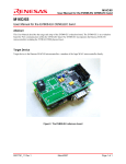
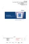
Proprietary Information IT700 Y-NET Package Quick Start February 1, 2009 Copyright © Yitran Communications Ltd. PRELIMINARY information concerns products in the formative or design phase of development. Characteristic data and other specifications are design goals. YITRAN Communications reserves the right to change or discontinue these products without notice. Please be aware that an important notice concerning availability, standard warranty, and use in critical applications of YITRAN Communications semiconductor products and disclaimers thereto appears at the end of this document. The IT700 Y-NET Package Quick Start IT700-UM-004-R1.6 Proprietary Information Table of Contents TABLES ....................................................................................................................................................................... 3 1 INTRODUCTION ............................................................................................................................................... 4 1.1 SCOPE ............................................................................................................................................................ 4 1.2 OVERVIEW ..................................................................................................................................................... 4 1.2.1 The Network Layer Features ............................................................................................................... 5 1.2.1.1 NL Topology ...................................................................................................................................... 6 1.2.1.2 Addressing Services........................................................................................................................... 7 1.2.1.3 Routing Services ................................................................................................................................ 7 1.2.1.4 Data Services..................................................................................................................................... 8 1.2.2 Technical Specifications ...................................................................................................................... 8 1.2.2.1 PHY Specifications ............................................................................................................................ 8 1.2.2.2 NL Management Specifications ......................................................................................................... 9 1.2.2.3 NL Data Specifications...................................................................................................................... 9 1.3 Y-NET PACKAGE CONTENT ........................................................................................................................ 10 1.3.1 The STK4 – (Starter Kit) .................................................................................................................... 11 1.3.2 The CD ................................................................................................................................................ 12 1.3.2.1 Software Application ....................................................................................................................... 12 1.3.2.2 Documentation: ............................................................................................................................... 12 2 WORKING WITH THE PACKAGE.............................................................................................................. 13 2.1 EVALUATION USER MODE OPTIONS ........................................................................................................... 13 2.1.1 Coverage Test Mode ........................................................................................................................... 13 2.1.1.1 Requirements ................................................................................................................................... 13 2.1.1.2 Evaluation Steps .............................................................................................................................. 14 2.1.2 Peer To Peer Mode ............................................................................................................................. 14 2.1.2.1 Requirements ................................................................................................................................... 15 2.1.2.2 Evaluation steps .............................................................................................................................. 15 2.1.3 Basic NL Setup Mode ......................................................................................................................... 16 2.1.3.1 Requirements ................................................................................................................................... 16 2.1.3.2 Evaluation steps .............................................................................................................................. 17 2.2 DEVELOPMENT PROCESS AND OPTIONS ...................................................................................................... 20 2.2.1 Required Documentation ................................................................................................................... 20 2.2.2 Implementation Options ..................................................................................................................... 21 2.2.2.1 PC .................................................................................................................................................... 21 2.2.2.2 External uP...................................................................................................................................... 21 2.2.3 Choosing Application Requirements ................................................................................................. 22 2.2.4 Implementation................................................................................................................................... 22 3 FREQUENTLY ASKED QUESTIONS (FAQ) .............................................................................................. 23 DOCUMENT CONTROL ........................................................................................................................................ 25 IMPORTANT NOTICE ........................................................................................................................................... 26 Copyright © 2009 Yitran Communications Ltd. Page 2 of 26 The IT700 Y-NET Package Quick Start IT700-UM-004-R1.6 Proprietary Information Figures Figure 1: The Tree Type NL Topology ......................................................................................................................... 6 Figure 2: Y-NET Package ........................................................................................................................................... 10 Figure 3: IT700 PIM ................................................................................................................................................... 11 Figure 4: IT700 STK4 and Board ............................................................................................................................... 11 Figure 5: LED Display on STK4................................................................................................................................. 14 Figure 6: Peer To Peer Setup....................................................................................................................................... 16 Figure 7: Basic NL Setup ............................................................................................................................................ 18 Figure 8: Network‟s Topology Display on PLC Studio .............................................................................................. 19 Figure 9: PC Program Application Development ....................................................................................................... 21 Figure 11: External uP/Own Board Application ......................................................................................................... 21 Tables Table 1: PHY Specifications ......................................................................................................................................... 8 Table 2: NL Management Specifications ...................................................................................................................... 9 Table 3: NL Data Specifications ................................................................................................................................... 9 Table 4: Y-NET Package Contents ............................................................................................................................. 10 Copyright © 2009 Yitran Communications Ltd. Page 3 of 26 The IT700 Y-NET Package Quick Start IT700-UM-004-R1.6 Proprietary Information 1 Introduction 1.1 Scope This document reviews the content of the IT700 Y-NET Package and provides the required information to allow a quick and smooth start for various evaluation and development purposes; from a simple peer-to-peer communication up to an advanced large scale PLC network. This document describes the technical specifications of the Y-NET package and the new features for this version. Follow the instructions in this document to get started and learn how to work with the Y-NET Package in its different modes. 1.2 Overview The Y-NET package is designed to enable evaluation, testing and application development with Yitran‟s IT700 networking technology to provide solutions for command and control applications such as Energy Management, Automatic and Remote Metering, Home/Building Automation, Lighting and HVAC control and more. The IT700 is a highly integrated System-on-a-Chip (SoC) Powerline Communication (PLC) modem. It incorporates Yitran‟s extremely reliable Physical Layer (PHY), high-performance Data Link Layer (DLL) and Network (Y-Net) protocol. The Network Layer (NL) is implemented using an advanced and compact adaptive routing and automatic addressing mechanism, enabling optimal and simple Powerline Communication. The IT700‟s PHY is optimized for PLC media and provides the following features: Differential Code Shift Keying (DCSK) - Yitran‟s patented modulation technique, which provides extremely high communication reliability. High immunity to signal fading, various noise characteristics, impedance modulation and phase/frequency distortion. A high in-phase and cross-phase reliability and an error correction CRC-16 mechanism. Meets worldwide regulation requirements (FCC, ARIB and CENELEC). Multiple transmission modes – Standard Mode (SM), Robust Mode (RM) and Extremely Robust Mode (ERM). Copyright © 2009 Yitran Communications Ltd. Page 4 of 26 The IT700 Y-NET Package Quick Start IT700-UM-004-R1.6 Proprietary Information The IT700‟s DLL is designed for PLC networking and applications, and provides the following features: Support of up to 1023 logical networks with 2047 nodes per network. Acknowledged and Unacknowledged data transmission services and retransmission mechanisms. Carrier Sense Multiple Access with Collision Avoidance (CSMA/CA) channel access scheme. Patent pending adaptive back-off algorithm based on IEEE802.11 and optimized for the power line medium. Quality of Service (QoS). Yitran‟s technology has been extensively tested, proven to be high performance and selected by major leading companies and standardization bodies worldwide. Yitran‟s technologies provide an ideal solution for a variety of applications and support the implementation of various national and international standards and protocols. 1.2.1 The Network Layer Features The NL is designed to provide a set of services to create and maintain a tree type topology where the root of the tree is a Network Coordinator (NC) and the body and leaves of the topology are remote stations (RS). The network layer (NL) provides two main services: (1) Network formation and (2) Routing services. The network formation provides the function and procedural means to create a new network, admit stations to the network and maintain the entirety of the network. The Routing Services provide the functional and procedural means of transferring data sequences from a NC to a RS in a network, even if these lack a direct communication link. The RS also responds to service requests from the upper layers and issues service requests to the Data Link Layer (DLL). The Adaptive Routing and Addressing (ARA) module‟s NL services allow the upper layers to consider the power line media as a simple peer-to-peer communication service between NC and RS. The ARA also provides notifications to the upper layers upon significant events that may affect those layers (an interface to the upper layer). The following sections describe the services provided by the NL. Copyright © 2009 Yitran Communications Ltd. Page 5 of 26 The IT700 Y-NET Package Quick Start IT700-UM-004-R1.6 Proprietary Information 1.2.1.1 NL Topology The NL is designed to create a tree type topology, allowing efficient connectivity between all nodes in the network. The tree consists of a NC and RS, as described below: Network Coordinator - NC The NC functions as the concentrator of the network. Once a network is created, it assigns a Network ID to the NC; the Node ID of the NC is „1‟. As a concentrator of the network, the NC is the root of the tree. The networks topology is derived from the NC‟s Tables. Remote Station - RS The RS is a general name for all nodes in the tree which are not the root, i.e. body nodes and leaves. An RS can function as both an initiating station as well as a repeater and maintains both functions, or may be one or the other. The following figure describes an example of a tree type topology, the NC and RS: Figure 1: The Tree Type NL Topology Net ID: 54 NC ID = 1 RS ID = 5 RS ID = 4 RS ID = 6 RS ID = 3 RS ID = 2 The figure above describes a tree type topology network consisting of six elements. Notice the tree root where the NC is given the address 54.1 (where 54 denotes the network ID, and 1 denotes the node ID). Other nodes are numbered from 2 to 6 and are organized randomly, simulating the creation of a PLC network topology. Example: If RS 54.2 (the initiating station) transmits a message to the NC, the message will be sent using Table Routing (special small sized tables in each RS) through stations 54.4 and 54.5, which function as Repeaters, to the NC (54.1). Copyright © 2009 Yitran Communications Ltd. Page 6 of 26 The IT700 Y-NET Package Quick Start IT700-UM-004-R1.6 Proprietary Information 1.2.1.2 Addressing Services Every node has a factory assigned serial number, which is a 16 bytes identification number. However, using this number for communication purposes is inefficient. Therefore, a logical ID is assigned to each node by giving it a Network ID and a Node ID. The DLL requires the upper layers to assign these logical IDs before normal communication can begin. The Network Layer provides an automatic addressing mechanism responsible for selecting a network address by the NC and associating nodes (RS) with the network by assigning logical addresses to nodes in the network. The two main functions are: 1. Network ID service: - Forming a new network by selecting a network address. - Resolving conflicts with other networks. - Maintenance of the uniqueness of the network address. 2. Node ID service: 1.2.1.3 - Associating nodes in the network with the network, by assigning addresses to nodes. - Maintaining nodes‟ addresses in the data base. - Resolving node address conflicts. - Node admission modes (automatic, based on the CNC number or controlled by Upper Layer). - Node approval network association, according to the node‟s Node Key. Routing Services The DLL provides communication where there is a direct link between the transmitter and receiver nodes. However, when there is no physical connection between the two nodes, routing functions are required and provided by the NL. The NL provides two services, packet routing and route discovery and maintenance. The NL provides the functions for an automatic formation of a tree type topology by defining a concentrator node, the NC and multiple nodes serving as repeaters and end-nodes in the network (RS). The automatic routing is responsible of identifying, creating and maintaining a route between every node in the network and the NC. The main functions are: 1. Route Discovery: - Every node discovers its route to the concentrator and vice versa. 2. Route Maintenance and Self Recovery: - Direct parent link maintenance – the link to the direct parent is continuously maintained. Copyright © 2009 Yitran Communications Ltd. Page 7 of 26 The IT700 Y-NET Package Quick Start IT700-UM-004-R1.6 Proprietary Information - Concentrator route maintenance – the entire route to the concentrator is maintained. 3. Route Optimization: - The route to the concentrator is continuously optimized. 4. Concentrator Recovery: - The NC, upon reset, retrieves the networks data from the non-volatile memory. - Recovery from NC replacement. The NC, after disconnection from its RS is „replaced‟. The NC is then given a new Net ID and the network will be built over again. 1.2.1.4 Data Services Data Services are responsible for the transmission and reception of packets. The NL receives data packets from the upper layers (the application) and passes it on the lower layers (the DLL) and vice versa. The NL performs the packet routing according to the route information created by the automatic routing services. 1.2.2 Technical Specifications 1.2.2.1 PHY Specifications The following table described the PHY technical specifications: Table 1: PHY Specifications Parameter Value Dynamic Range 90 dB Narrowband Interference (At least) -30 dB AWGN Interference (At least) -4 dB Maximum Data Rate Copyright © 2009 Yitran Communications Ltd. FCC 7.5 Kbps ARIB 7.5 Kbps CENELEC A 2.5 Kbps CENELEC B 2.5 Kbps Page 8 of 26 The IT700 Y-NET Package Quick Start IT700-UM-004-R1.6 Proprietary Information 1.2.2.2 NL Management Specifications The following table describes NL Management technical specifications: Table 2: NL Management Specifications Parameter Value Maximum Network Depth 16 Maximum Number of Overlapping Networks 1023 Maximum RS Nodes in Logical Network 1400 Performance1 1.2.2.3 RS Connection to NC < 30 sec Route Fail Detection < 1 minute NL Data Specifications The following table describes the maximal payload size supported by the NL Data services: Table 3: NL Data Specifications Parameter Value Single Fragment Internetworking Unicast 87 bytes Internetworking Broadcast 103 bytes Intranetworking source routing service 88 bytes Intranetworking table routing service 105 bytes Intranetworking direct Unicast service 110 bytes Intranetworking Broadcast service 110 bytes Intranetworking source routing service 1738 bytes Intranetworking table routing service 1755 bytes Intranetworking direct Unicast service 1760 bytes Fragmented 1 The Performance values mentioned in Table 2 are relevant for a network with 20 RS. Increasing the network size will result in different performance values. For performance values in other network sizes, please refer to the IT700 NL Parameter Configuration Recommendations application note. Copyright © 2009 Yitran Communications Ltd. Page 9 of 26 The IT700 Y-NET Package Quick Start IT700-UM-004-R1.6 Proprietary Information Intranetworking Broadcast service 1760 bytes 1.3 Y-NET Package Content The following table describes the items included in the Y-NET Package: Table 4: Y-NET Package Contents Item STK4 (Starter Kit) Quantity NC (Network’s Coordinator) One RS (Remote Station) Five CD – Software and Documentation One The following figure shows an example of the contents of the Y-NET Package: Figure 2: Y-NET Package Copyright © 2009 Yitran Communications Ltd. Page 10 of 26 The IT700 Y-NET Package Quick Start IT700-UM-004-R1.6 Proprietary Information 1.3.1 The STK4 – (Starter Kit) The STK4 for NC and RS are identical where the difference between the two is in the embedded software configuration. The STK4 serves as a mother board for IT700 Plug-In Module (PIM) and enables evaluation of the IT700 performance, development of PLC (Power Line Communication) enabled products, and creation of a multiple-node testing set-up. Each STK4 (NC/RS) consists of Mother Board, IT700 PIM, Power Supply unit and USB-Cable. The following figure shows an example of an IT700 PIM: Figure 3: IT700 PIM The following figure shows an example of the IT700 STK4 and the board inside: Figure 4: IT700 STK4 and Board Copyright © 2009 Yitran Communications Ltd. Page 11 of 26 The IT700 Y-NET Package Quick Start IT700-UM-004-R1.6 Proprietary Information 1.3.2 The CD The CD consists of the following: 1.3.2.1 Software Application IT700 PLC Studio – This application is used for direct communication with each node. The application allows node control and monitoring. 1.3.2.2 Documentation: 1. This Document (IT700 Y-NET Package - Quick Start) 2. IT700 STK4 User Manual This document describes the IT700 STK4 (Starter Kit) platform, its usage and configuration options. IT700 PLC Studio User Manual This document describes the PLC Studio PC application used with the IT700 based platform. It includes installation instructions, an overview of its different configurations options and display screens, and test examples. 3. IT700 Host Interface Command Set User Guide The Host Application interfaces with the IT700 via a UART physical interface. This document describes the interface for host applications operating above the IT700 modem, on which the YNET protocol stack resides. The document reviews the YNET protocol stack‟s supported functions and processes, provides guidelines for creating new applications and allows for an in-depth understanding of the host interface‟s available commands for implementing host applications above IT700. 4. IT700 Data Sheet The Data Sheet provides a full review of the IT700 IC including pins description, general block diagram, electrical specifications and package information. In addition the document provides functional description of the IT700‟s AFE, Physical Layer, internal 8051 controller and Y-NET Protocol. Copyright © 2009 Yitran Communications Ltd. Page 12 of 26 The IT700 Y-NET Package Quick Start IT700-UM-004-R1.6 Proprietary Information 2 Working with the Package The Y-NET package is designed to enable evaluation, testing and application development with Yitran‟s technology. The User Mode Options are divided to: Evaluation User Mode Options. Development Process and Options. 2.1 Evaluation User Mode Options For evaluation of IT700 based technology, there are four user-modes described in this chapter. These modes range from a simple coverage test mode to a complicated network system. The following sections describe each usermode and provide the requirements and implementation steps for each evaluation process. Note that the Evaluation User Modes described in this document are designated for the Y-NET Package content only and allow evaluation of a network of the specified scale. 2.1.1 Coverage Test Mode The Coverage Test Mode is a simple test to assess connectivity via the power line grid. In this mode, two STK4s, a NC and a RS are used. Connectivity is confirmed using the LED labeled LINK on the RS. 2.1.1.1 Requirements 1. The required Hardware: Two STK4s: o 1 RS o 1 NC 2. The required Software: There is no required software for this mode. 3. The required Documentation: IT700 STK4 User Manual Copyright © 2009 Yitran Communications Ltd. Page 13 of 26 The IT700 Y-NET Package Quick Start IT700-UM-004-R1.6 Proprietary Information 2.1.1.2 Evaluation Steps 1. Connect the NC STK4 to the PSU (Power Supply Unit) and then a plug/socket and turn on the board (black switch). 2. Check that the LED labeled ON is lit. 3. Take an RS STK4 and connect it to a different power supply (plug/socket) and turn on the board. 4. Check that the LED labeled ON is lit. 5. Wait several seconds, a minute at the most, and check that the LED labeled LINK is lit. If the LED labeled LINK is lit, the RS is connected to the NC, connectivity exists and the coverage test succeeded. Otherwise, try connecting the RS to a different power supply and repeat the steps above. Figure 5: LED Display on STK4 On Link Tx Rx IT800-STK2 Note For enabling evaluation without usage of PC running the PLC Studio (evaluation preformed using the link led indicating Connectivity), the modem must be configured to AUTOMATIC START mode to allow IT700 operation without need for external initialization. Refer to the PLC Studio User Manual for more details about this configuration option. 2.1.2 Peer To Peer Mode Peer to Peer evaluation assesses the connectivity and throughput of the PLC link between the two stations using the PLC Studio application. This mode enables both evaluation and product development. This mode requires two STK4s and the PLC Studio software. It requires a basic setup of two STK4s and installation of the PLC Studio on a PC. Copyright © 2009 Yitran Communications Ltd. Page 14 of 26 The IT700 Y-NET Package Quick Start IT700-UM-004-R1.6 Proprietary Information 2.1.2.1 Requirements 1. The required Hardware: Two STK4s: o 1 NC o 1 RS 2. The required Software: PLC Studio - The PLC Studio may be installed on one PC using two USB ports (virtual COM Ports) or it may be installed on two different PCs. 3. The required Documentation: 2.1.2.2 IT700 STK4 User Manual IT700 PLC Studio User Manual Evaluation steps 1. Install the PLC Studio application from the package CD on your PC. (Installation instructions can be found in the IT700 PLC Studio User Manual.) 2. Connect the STK4 to the PSU (Power Supply Unit) and then a plug/socket and turn on the board (black switch). 3. Using the USB cable, connect the STK4 to the desired USB port of the PC. 4. Repeat steps 1-3 for a second STK4 but use a different plug/socket and a different PC (or to the same PC, but to a different USB port). 5. Use the two PLC Studios to evaluate the connectivity by transmitting data and checking its reception. To configure settings and controlling the various options, refer to the IT700 PLC Studio User Manual. Copyright © 2009 Yitran Communications Ltd. Page 15 of 26 The IT700 Y-NET Package Quick Start IT700-UM-004-R1.6 Proprietary Information Figure 6: Peer To Peer Setup IT700 STK4 IT700 STK4 2.1.3 Basic NL Setup Mode The NL Setup mode allows the user to test the NL services of the IT700 (refer to Section 1.2.1). Testing these services will allow the user to learn the addressing and routing functionalities provided by the NL ARA (Adaptive Routing and Addressing) mechanism. The user may view the topology of the system (displayed by the PC connected to the NC) and examine its connectivity by transferring packets between various stations in the network. 2.1.3.1 Requirements 1. The required Hardware: STK4 (at least two, recommended to use 6 for full evaluation) o 1 NC o The rest - RS 2. The required Software: PLC Studio - The PLC Studio may be installed on one PC only connected to the NC. The PLC Studio for IT700, allows configuring the RS via the NC. 3. The required Documentation: IT700 STK4User Manual IT700 PLC Studio User Manual Copyright © 2009 Yitran Communications Ltd. Page 16 of 26 The IT700 Y-NET Package Quick Start IT700-UM-004-R1.6 Proprietary Information 2.1.3.2 Evaluation steps 1. Connect the STK4s to the PSU (Power Supply Unit) and then a plug/socket and turn on the boards (black switch). 2. Locate the stations in various locations (note: if there is direct link between all nodes than the network topology will be flat – all nodes will be directly connected to the NC). 3. View the network‟s topology on the PLC Studio connected to the NC in order to learn the addresses of the different nodes in the network and to initiate communication. 4. Examine the data of the transferred packets for evaluation of the network establishment and maintenance. Copyright © 2009 Yitran Communications Ltd. Page 17 of 26 The IT700 Y-NET Package Quick Start IT700-UM-004-R1.6 Proprietary Information Figure 7: Basic NL Setup IT700 STK4 PLC Studio IT700 STK4 IT700 STK4 IT700 STK4 IT700 STK4 IT700 STK4 PLC Studio Note The power line links and parent links described in the figure above are for illustration purposes only. Your network may be constructed automatically with different links. Copyright © 2009 Yitran Communications Ltd. Page 18 of 26 The IT700 Y-NET Package Quick Start IT700-UM-004-R1.6 Proprietary Information Figure 8: Network’s Topology Display on PLC Studio Note The Node IDs displayed on the topology screen above will not necessarily be the same Node IDs in your created network. Copyright © 2009 Yitran Communications Ltd. Page 19 of 26 The IT700 Y-NET Package Quick Start IT700-UM-004-R1.6 Proprietary Information 2.2 Development Process and Options For product development with the IT700, follow the sections describing the development process below. The user should first read the required documentation, plan the application structure and content, and then perform the implementation. 2.2.1 Required Documentation Reading and learning the following documents are essential for further development. 1. IT700 Host Interface Command Set User Guide This document describes the interface of the IT700 and explains how to interface with the IT700; configure and monitor parameters, transmit data, receive data and more. 2. IT700 Host Interface SW (Software) Example This document describes the application Software Example for the IT700 provided by Yitran. The Software Example is available for developers by request from Yitran, as a reference for implementation of further development. Copyright © 2009 Yitran Communications Ltd. Page 20 of 26 The IT700 Y-NET Package Quick Start IT700-UM-004-R1.6 Proprietary Information 2.2.2 Implementation Options The development of the application interfacing with the IT700 may take place in any of the following: 2.2.2.1 PC This option allows for the development of a PC program application which interfaces with the IT700. Use this implementation option for enabling settings and configuration of the IT700, controlling of message transmission and reception, statistics, file transfer and more. Figure 9: PC Program Application Development IT700 – STK4 IT700 IT800 -STK4 STK2 On Link Tx Rx USB PC Program Application Development IT800-STK2 2.2.2.2 External uP This option allows for the development of a program for an „Own Board‟ uP, interfacing with the IT700 through UART. Use this implementation option for development of a substantive product. Different configurations, settings, control and monitoring of the IT700 is maintained via the Own Board uP. Figure 10: External uP/Own Board Application IT700 – STK4 IT800 -STK4 STK2 IT700 On Link Tx Rx UART ‘Own Board’ Application Development External uP IT800-STK2 Copyright © 2009 Yitran Communications Ltd. Page 21 of 26 The IT700 Y-NET Package Quick Start IT700-UM-004-R1.6 Proprietary Information 2.2.3 Choosing Application Requirements An important stage of the development process is planning the application, its different options and functions, and features to be included. When developing an application the user should to take into consideration developing two types of interfaces; the concentrator of the network (NC) and the end-nodes/repeaters of the network (RS). The following options refer to the functions that may be included in the application: Common Functionalities 1. Initialization 2. Packet Transmission (Tx) 3. Packet Reception (Rx) 4. Parameters Configuration and Monitoring NC Functionalities 1. Network Monitoring (access to Addressing and Routing tables) 2. Admission Conditions RS Functionalities 1. RS Monitoring 2. RS Joining Conditions 2.2.4 Implementation After reading the necessary documentation and planning the application, the implementation itself may begin. In order to implement the desired application follow the IT700 Host Interface Command Set User Guide, in which the implementation of each command is described. For easier implementation of the necessary code, refer to the software example documents (available by request from Yitran). Copyright © 2009 Yitran Communications Ltd. Page 22 of 26 The IT700 Y-NET Package Quick Start IT700-UM-004-R1.6 Proprietary Information 3 Frequently Asked Questions (FAQ) This section consists of frequently asked question about general topics related to the IT700 technology. Q: What is the maximum range for a single hop communication using IT700? A: There is no real meaning to a maximal range for the power line communication since the distance depends on the power line conditions (noise, load, etc.). The IT700 signal can run for several kilometers under ideal power line conditions (i.e. mid-voltage). When the power line conditions are not ideal and the modem „suffers‟ from heavy load and noises the distance will be shorter, but it will still provide full connectivity (communication between every two nodes) in standard size houses. Q: What is the modem‟s performance in terms of SNR and Dynamic range? A: IT700 provides over 90 db of dynamic range, (-5) db SNR for AWGN and (-30) db SNR for CW Interference (communicating even under negative SNR). Q: Can two modems communicate if they are located on different phases? Is a phase coupler required? A: Communication between different phases can exist due to inductance between the phases. The problem with most PLC technologies is that the quality of the signal after passing from one phase to another is very poor and does not stand in the minimal modem requirements (SNR, dynamic Range etc.) for performing communication. Due to the robustness and the ability to perform communication in negative SNR and bad power line conditions, on standard size houses with normal power line conditions, IT700 can perform cross-phase communication with no need for external phase coupling. But, when trying to communicate over “long distances” and over different phases (i.e modem X located on floor 1 plugged to phase 1 and modem Y located on floor 5 plugged to phase 2), there is a possibility that the modems will not overcome both the distance and cross-phasing. In this case you might need to use an external phase-coupler. Q: What is the actual data rate and how do I reach the maximal rate? A: In order to reach maximal data rate, send single burst packets with maximal payload length. The actual data rate should reach ~1.3K in CENELEC-B band and ~4K in FCC band. Copyright © 2009 Yitran Communications Ltd. Page 23 of 26 The IT700 Y-NET Package Quick Start IT700-UM-004-R1.6 Proprietary Information Q: Does the modem work even when there is no power on the lines? A: The modem does not require the AC power in order to perform communication. In fact, if there is no power on the lines the communication conditions are ideal since IT700 will not suffer from noises or load. Q: Can the modem work on a DC line? A: Yes. Q: What is the difference between IT700 and IT800D/IT800Y? What do I need to do in order to upgrade from IT800Y to IT700? A: The main difference is that IT700 integrates into the chip most of the Analog components surrounding the IT800 (line driver, filters). The fact that IT700 requires a minimal number of components surrounding the IC leads to a very cheap solution. The first version of IT700 will include PHY, DLL and Networking layers. The PHY and DLL are identical to PHY and DLL of the IT800D and IT800Y. The Networking layer and Logical Interface Command Set are identical to the interface provided by the IT800Y-v1. An additional benefit of IT700 is that it will allow on chip programming (no need for application controller). The on-chip programming option will be available a few months after first release of IT700. Q: Is there a different price for NC PIM compared to the RS PIMs? A: Both “NC” and “RS” modules contain exactly the same software and hardware (in very big networks we might add external EEPROM to the NC). The node‟s operation mode (NC/RS) is a simple configuration and can be easily done by the application. Q: What is the typical power consumption of IT700 while it is on Idle (Rx)? A: The IT700 typical consumption (RX) is ~250 mW. More information about IT700 consumption and power supply requirements are detailed in IT700 Data Sheet. Copyright © 2009 Yitran Communications Ltd. Page 24 of 26 The IT700 Y-NET Package Quick Start IT700-UM-004-R1.6 Proprietary Information Document Control Revision 1.0 1.1 1.2 1.3 1.4 1.5 1.6 Date February 1, 2009 June 18, 2009 November 2, 2009 November 30, 2009 October 26, 2010 November 3, 2010 Copyright © 2009 Yitran Communications Ltd. Description Creation Updated for STK3 Section 2.2.2.2 removed (no longer relevant) Page 9, Table 2 – Maximum Network Depth corrected & Maximum Number of Overlapping Networks added. “Preliminary” removed STK3 changed to STK4 Page 25 of 26 The IT700 Y-NET Package Quick Start IT700-UM-004-R1.6 Proprietary Information Important Notice Yitran Communications (“Yitran”) reserve the right to make changes to their products or to discontinue any product or service without notice, and advise customers to obtain the latest version of relevant information to verify, before placing orders, that information being relied on is current and complete. All products are sold subject to the terms and conditions of sale supplied at the time of order acknowledgement, including those pertaining to warranty, patent infringement, and limitation of liability. Yitran warrants performance of its products to the specifications applicable at the time of sale in accordance with Yitran‟s standard warranty. Testing and other quality control techniques are utilized to the extent Yitran deems necessary to support this warranty. Specific testing of all parameters of each device is not necessarily performed, except those mandated by government requirements. CERTAIN APPLICATIONS USING SEMICONDUCTOR PRODUCTS MAY INVOLVE POTENTIAL RISKS OF DEATH, PERSONAL INJURY, OR SEVERE PROPERTY OR ENVIRONMENTAL DAMAGE (“CRITICAL APPLICATIONS”). YITRAN‟S PRODUCTS ARE NOT DESIGNED, AUTHORIZED, OR WARRANTED TO BE SUITABLE FOR USE IN LIFE–SUPPORT DEVICES OR SYSTEMS OR OTHER CRITICAL APPLICATIONS. INCLUSION OF YITRAN‟s PRODUCTS IN SUCH APPLICATIONS IS UNDERSTOOD TO BE FULLY AT THE CUSTOMER‟S RISK. In order to minimize risks associated with the customer‟s applications, the customer to minimize inherent or procedural hazards must provide adequate design and operating safeguards. Yitran assumes no liability for applications assistance or customer product design. Yitran does not warrant or represent that any license, either express or implied, is granted under any patent right, copyright, mask work right, or other intellectual property right of Yitran covering or relating to any combination, machine, or process in which such semiconductor products or services might be or are used. Yitran‟s publication of information regarding any third party‟s products or services does not constitute Yitran‟s approval, warranty or endorsement thereof. Copyright © 2009 Yitran Communications Ltd. Page 26 of 26