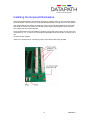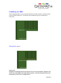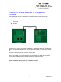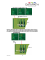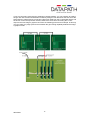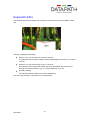
1
Express9
User Manual
UK Headquarters
Datapath Ltd., Alfreton Road, Derby, DE21 4AD, UK
Tel: +44 (0) 1332 294441 Fax: +44 (0) 1332 290667
Email [email protected]
www.datapath.co.uk
1
09/03/2011
Contents
Contents .......................................................................................................... 2
Specifications: .................................................................................................. 3
Introduction ...................................................................................................... 4
Features ................................................................................................................................. 4
Unpacking ........................................................................................................ 5
Requirements ......................................................................................................................... 5
Installing the Express9 Backplane ................................................................... 6
Installing an SBC ............................................................................................. 7
Express9 slot layout ............................................................................................................... 7
Connecting a Host Machine to an Expansion Chassis..................................... 8
Connecting more than one Chassis ................................................................. 9
Gen-locking Cables on H-Link and S-Link Boards ................................................................ 9
Express9 LED’s ............................................................................................. 12
Datapath Limited ............................................................................................ 13
Technical Support ................................................................................................................ 13
Copyright Statement ............................................................................................................ 13
Index .............................................................................................................. 15
2
09/03/2011
Specifications:
Express9
Max Power
16W
Power requirements
Max current at +3.3V - 0.5A
Max current at +12V – 0.5A
Max current at +5V – 1.5A
Form Factor
PICMG1.3 Host SBC interface
1 x PCIe (x8) expansion slot
ATX PSU
4 x 24 pin power connectors
SATA Ports
2 x ports via PICMG1.3 interface
USB Ports
2 x ports via PICMG1.3 interface
S-Link
Max Power
5W
Power requirements
Max current at +3.3V – 0.1A
Max current at +12V – 0.3A
Max current at +5V – 0.1A
Form Factor
PICMG1.3
PCIe x 8 expansion interface
H-Link
Max Power
5W
Power requirements
Max current at +3.3V – 0.1A
Max current at +12V – 0.3A
Form Factor
PCIe x 8
Environment: Express9/Slink/Hlink/Ex-cable
Operating Temperature
0 to 35 deg C
Storage Temperature:
-20 to 70 deg C
Relative Humidity:
5% to 90% non-condensing
3
09/03/2011
Warranty
3 Years
Introduction
The Datapath Express9 backplane provides nine PCI express slots and can be used with a
standard PICMG 1.3 SBC as a stand alone system or with the Datapath S-Link and H-Link
cards to provide a PCIe expansion system for a standard PC.
Features
Nine slot PCIe backplane. 8 x 4 lane slots plus 1 x 8 lane slot
All slots implemented as x 16 physical connectors so any width PCIe card can be
accommodated
1 x PICMG 1.3 SBC slot
Use as a PCIe expansion backplane for a standard PC using the S-Link and H-Link
cards
Compatible with a standard 4U IPC chassis
Support for daisy chaining multiple backplanes
PCIe Switch Fabric providing 192 Gb/s peak system bandwidth
4
09/03/2011
Unpacking
Your packing box should contain the following items:
Express9 Backplane
SBC1 (optional)
S-Link Card (optional)
H-Link Card (optional)
Ex-cable (optional)
Datapath CD containing the user manual
Note:
All PCB’s are static sensitive and are packed it anti-static materials. Please keep the
Express9 Backplane and any plug-in card in its packaging until you are ready to install
and observe anti static precautions when installing this product.
Requirements
To install the Express9 backplane you require:
ATX Power supply
Chassis
Host Computer
5
09/03/2011
Installing the Express9 Backplane
The Express9 backplane is fixed into the chassis by screwing down on the mounts located in
the host chassis. Ensure the rear of the Express9 backplane is facing the rear of the chassis.
The chassis will have a number of locating mounts not used by the Express9, it is important
that stand off mounts are used to ensure the reverse side of the backplane does not come
into contact with any unused mounts.
Once the Express9 is secured inside the chassis connect the power supply to one of the four
connectors (J1, J2, J3, and J4) on the Express9 backplane and connect the 12v supply (J5 or
J6).
Connect the fan headers
There is no requirement to connect the power reset cable unless using an SBC.
6
09/03/2011
Installing an SBC
When installing an SBC onto the Express9 backplane the SBC should be carefully inserted
into the PICMG1.3 SBC slot. The SBC should be installed as per the manufacturer’s
instructions.
Express9 slot layout
Please note
Datapath recommend that the first (x8) PCIe slot is not occupied with a graphics card
as this can cause BIOS issues with certain chipsets. This slot should be reserved as
the expansion slot or for a non-VGA device.
7
09/03/2011
Connecting a Host Machine to an Expansion
Chassis
The Express9 can be used as an expansion chassis providing you have the following
accessories:
H-Link card
S-Link card
Ex-cable
Power down the host machine and insert the H-Link card into a free x8 PCIe slot.
Insert the S-Link card into the PICMG1.3 SBC slot on the Express9 as shown in the diagram
above. The S-Link card should occupy the first half of the PICMG1.3 slot (connectors A and
B).
Connect the H-Link and S-Link cards using the Ex-cable.
When powering up the host machine the expansion chassis will power up automatically, the
LED for the PICMG1.3 slot containing the S-Link card will flash indicating that a successful
link has been made between the host machine and the expansion chassis.
Note:
When inserting PCI cards into the host machine or expansion chassis, ensure the
system is powered down prior to any cards being installed.
8
09/03/2011
Connecting more than one Chassis
It is possible to connect more than one expansion chassis to a host machine increasing the
number of PCIe slots available.
The following diagram illustrates how this can be achieved:
In this instance the host machine is an Express9 backplane with an SBC fitted.
When connecting two expansion chassis to a host machine the H-Link card in the first
expansion chassis must be installed into the x8 slot.
The S-Link card in the second expansion chassis should be installed in the PICMG1.3 SBC
slot.
Connect the H-Link and S-Link cards using the Ex-cable as shown in the above illustration.
Gen-locking Cables on H-Link and S-Link Boards
Connectors J4 and J5 are used for Gen-locking multiple chassis together. This is useful when
using multiple chassis that each contains a number of Datapath Image4 graphics cards. The
gen-locking chain can be used to tie the outputs of the graphics cards together so that they all
render their outputs to the screen at the same time. This makes fast moving images appear
smoother on the video/data wall and eliminates ‘tearing’ artefacts on the display.
To create a gen-locked chain using the H-Link and corresponding S-Link cards, firstly ensure
that the system is powered down. Then connect the gen-locked output of the closest Image 4
graphics card to connector J4 (GEN LOCK IN) on the H-Link board using the cable supplied
with your H-Link board, as shown in the picture below. Note that this cable is longer than the
cable supplied with each Image 4 graphics card in order to cover the extra distance between
the Image4 and the H-Link board. This will send the gen-locked clock over the Ex-cable to the
next downstream chassis.
9
09/03/2011
In order to complete the gen-locked link, you will need to connect the output of the S-Link
board in the downstream expansion chassis back into the next Image 4 graphics card in the
chain, as per the following image. Note again that the cable supplied with the S-Link board is
longer than those supplied with the Image4 graphics card in order to cover the extra distance.
10
09/03/2011
If you are connecting more than two expansion chassis together, you can continue to expand
the gen lock link to further downstream chassis by fitting a H-link board into the first slot of the
first expansion chassis and by connecting a Gen-lock cable from the S-Link board directly into
the H-Link card in the expansion chassis, whilst at the same time connecting the H-Link
output to the next Image 4 graphics card. See the following picture as an example. In this way
you can create very large systems and maintain the gen locking capability between all Image
4 graphics cards.
11
09/03/2011
Express9 LED’s
The Datapath Express9 backplane has an LED for each PCIe slot and the PICMG1.3 SBC
slot.
The LED’s indicate the following:
Flashes on for 1.5 seconds then off for 0.5 seconds.
This indicates that the full lane width has been established for that slot e.g. x4 card in
a x4 slot
Flashes on for 0.5 seconds then off for 1.5 seconds.
This indicates that a reduced lane width has been established and the slot is not
working to maximum efficiency e.g. a x1 card inserted into a x4 slot.
No LED’s flashing.
This indicates that lane width has not been established.
The LED’s will not flash on slots where no cards are fitted.
12
09/03/2011
Datapath Limited
Datapath has a long and very successful history in the computer graphics industry. Datapath
has been designing and supplying high performance, high quality graphics display systems to
the worlds largest and most demanding companies and institutions since 1982. Datapath
was one of the founding companies of multi-screen Windows acceleration using single and
multi board solutions. Now using the very latest display technology Datapath offers some of
the world’s leading multi screen graphics accelerators for the most demanding applications.
As new technology advances, so we at Datapath improve the performance and functionality
of both our hardware and software to give our customers more. Following a continuous
development program, we pride ourselves on our support and responsive nature towards all
our customers and their changing needs. As more sophisticated equipment and techniques
become readily available, so we are there to exploit the power and potential that this
technology presents.
Technical Support
Registered Users can access our technical support line using, email, and the Support page
on the Datapath Web Site, usually with a response within 24 hours (excluding weekends).
Via Email
Send an email to [email protected] with as much information about your system as
possible. To enable a swift response we need to know the following details:
Specification of the PC - including processor speed
Operating System
Application Software
Datapath Hardware / Software
The exact nature of the problem - and please be as specific as possible.
Please quote version and revision numbers of hardware and software in use wherever
possible.
Copyright Statement
© Datapath Ltd., England, 2009
Datapath Limited claims copyright on this documentation. No part of this documentation may
be reproduced, released, disclosed, stored in any electronic format, or used in whole or in
part for any purpose other than stated herein without the express permission of Datapath
Limited.
Whilst every effort is made to ensure that the information contained in this on-line help is
correct, Datapath Limited make no representations or warranties with respect to the contents
thereof, and do not accept liability for any errors or omissions. Datapath reserves the right to
change specification without prior notice and cannot assume responsibility for the use made
of the information supplied. Datapath Limited acknowledges all registered trademarks used
within this documentation.
13
09/03/2011
UK Headquarters and Main Sales Office
Datapath Ltd.,
Alfreton Road,
Derby, DE21 4AD, UK
Tel: +44 (0) 1332 294441
Fax: +44 (0) 1332 290667
Email: [email protected]
www.datapath.co.uk
French Office
Datapath France,
7 rue des Pinsons,
78990 Elancourt
Tel: +33 1 30 13 89 34
Fax: +33 1 30 13 89 35
Email: [email protected]
14
09/03/2011
Index
ATX Power supply, 5
Compatible, 4
connecting two expansion, 9
Copyright Statement, 13
daisy chaining, 4
Datapath Limited, 13
Environment, 3
Form Factor, 3
French Office, 14
H-Link, 8
increasing the number of PCIe slots, 9
Installing Vision Switch with Multiple iH4 Cards, 7
Introduction, 5
LED, 12
locating mounts, 6
Max Power, 3
packing box, 5
Power requirements, 3
Relative Humidity, 3
Requirements, 5
SBC, 7
S-Link, 3, 9
slot layout, 7
Specifications:, 3
stand off mounts, 6
Storage Temperature, 3
Switch Fabric, 4
Technical Support, 13
Unpacking, 5
15
09/03/2011