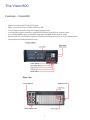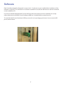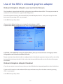
1
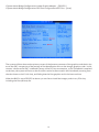
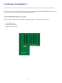
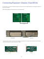
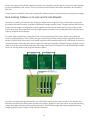
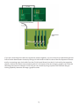
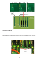
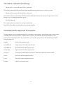
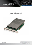
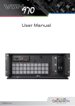
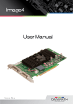
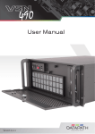
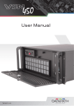
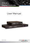
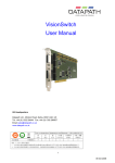
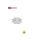
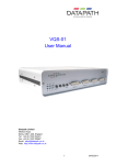
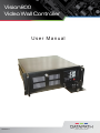
Vision800
Video Wall Controller
User Manual
16.08.2011
Contents
Safety Instructions3
Rack Mount Safety Instructions4
Introduction5
Unpacking6
The Vision8007
Specifications
8
Software9
Use of the SBC’s onboard graphics adaptor 10
Hardware Installation12
Connecting Expansion Chassis (Vision800X) 13
Datapath Limited18
Index20
Safety Instructions
To prevent damage to your Datapath product or injury to personnel operating the equipment, please read
the following safety precautions prior to operation. These instructions should be made available to all
those who will use and operate Datapath products.
Power Supply
All Datapath products require a mains power supply. This power supply must be disconnected when
equipment is being upgraded or relocated.
Cables
Do not expose cables to any liquids; doing so may cause a short circuit which could damage the
equipment. Do not place heavy objects on top of any cables as this can cause damage and possibly lead to
exposed live wires.
Ventilation
All computer equipment should be located in a well ventilated area. All ventilation holes on the computer
casing must be kept clear of any obstruction at all times. Failure to do so will result in the system over
heating and damaging your equipment.
Working Environment
The equipment should be located in an environment free from dust, moisture and extreme changes in
temperature and should be placed on a stable and solid work surface. Liquids (hot/cold drinks etc) should
not be placed near the equipment as spillage could cause serious damage.
Gas/Flammable Liquids
Electronic equipment should never be used in the presence of gas or any flammable liquid, doing so could
result in an explosion or serious fire.
Smoke/Unusual Smells
Should you notice smoke or unusual smells being emitted from your computer, turn off and unplug the
system from the mains supply. The system should then be passed to a qualified technician for
inspection. Continued operation could result in personal injury and damage to property.
Maintenance
Maintenance should only be carried out by competent technicians, any Datapath plug-in cards that are
physically damaged should be returned to Datapath for repair using Datapath RMA procedures.
Disposal
At the end of life all Datapath products should be disposed of as per local laws and regulations dictate. In
UK contact Datapath to arrange disposal. Our WEE registration number is WEEE/AA0005ZR.
3
Rack Mount Safety Instructions
Temperature
If Vision800 systems are to be installed in a closed or multi-unit rack assembly, the installation should be
such that the amount of air flow required for safe operation of the equipment is not compromised. The operating ambient temperature of the rack environment should be maintained below 35 degrees centigrade
under all conditions. Appropriate cooling arrangements should be built into the cabinet to ensure that this
specification is maintained.
Mechanical Loading
Mounting of the equipment in the rack should be such that a hazardous condition is not achieved due to
uneven mechanical loading.
Circuit Overloading
Consideration should be given to the connection of the equipment to the mains supply circuit and the
effect that overloading of the supply might have on any overcurrent protection or supply wiring. Appropriate consideration of equipment nameplate ratings should be used when addressing this concern.
Reliable Earthing
Reliable earthing of all rack-mounted equipment should be maintained. Particular attention should be
given to supply connections other than direct connections to the branch circuit (e.g. use of power strips).”
Introduction
The Vision800 controller is a highly expandable and flexible solution for video wall and multi-screen
display applications. The controller is optimised for operation with the latest generation of Datapath PCI
express graphics and video capture cards. The Vision800 can also be used with the Vision800X expansion
chassis.
The Vision800X is a general purpose 9-slot PCIe expansion chassis that can be used with any host PC to
expand the number of available PCIe slots. (Note: The host PC must have one x 8 lane slot available)
5
Unpacking
Your packing box should contain the following items:
• The Vision800 Chassis
• Express9 backplane (installed)
• SBC1 (installed)
• Mouse
• Keyboard
• Power cable
• Datapath CD ROM
• SBC documentation
If there are any discrepancies, you should contact Datapath immediately.
Note:
When shipped, the Vision800 contains transit packaging INSIDE the chassis, this must be removed
prior to operation.
To remove the packaging, remove the chassis lid via the two screws located on each side of the case.
6
The Vision800
Features – Vision800
•
•
•
•
•
•
•
Quad Core Industrial PC with 9 PCIe slots
SBC1 - Quad Core CPU 2.66 GHz PICMG1.3 SBC
1 to 40 Display channels using the Image4 graphics card
4 to 128 video capture channels using the VisionSD8 or VisionSD4+1 capture cards
1 to 32 RGB/HD/DVI capture channels using the VisionRGB-E1/E2 capture cards
Expand with 1 or 2 Vision800X expansion chassis providing a maximum of 25 PCI express slots
Compatible with Datapath Wall Control
7
Specifications
19” 4U Industrial PC chassis
Dimensions (approx) Length 500mm (incl handles, Height 177mm,
Width 481mm (incl mounting brackets)
SBC1 - Quad Core CPU 2.66 GHz PICMG1.3 SBC with VGA, dual Gigabit LAN, SATA RAID USB2.0 and 16-bit GPIO
4GB DDR2 system memory
Express9 PCIe back plane providing 1 x 8 lane slot and 8 x 4 lane slots
Two 500GB removable SATA hard drives
One DVD/RW combo drive
Two Gigabit Ethernet ports
VGA output. (Can be used as a control screen)
500 Watt Redundant PSU or 400 Watt ATX PSU
Dual cooling fans with removable air filter
Includes keyboard and mouse
Windows 7 64bit operating system
Operating temperature: 0 to 35 Deg C
3 year warranty on the Express9 backplane
Models
Vision800-RPSU
Controller chassis with 500 Watt RPSU
Vision800-ATX Controller chassis with 400 Watt ATX PSU
8
Software
Each Vision800 shipped by Datapath is custom built. If cards are not pre-installed then installation of the
software is required. For information on software installation consult the relevant user manual contained
on the installation CD.
If you have ordered Datapath Wall Control-PRO-HK software and this has been installed prior to shipment, please ensure the Wall Control hardware USB key is installed before system boot up.
To install the Wall Control hardware USB key remove from its packaging and insert it into a vacant USB
port as shown below:
9
Use of the SBC’s onboard graphics adaptor
Onboard Graphics Adaptor used as Control Screen
The Vision800 is shipped with the BIOS configured to boot off the onboard VGA. This output can then be
used as the control screen for a typical wall configuration.
To set the system to boot on the onboard VGA (“Internal Graphics Device” - IGD), enter setup from the
boot screen by pressing <DEL> as prompted.
In the BIOS setup utility select:
Chipset>North Bridge Configuration>Initiate Graphic Adapter - [IGD]
Chipset>North Bridge Configuration>PEG Port Configuration>PEG Port - [Auto]
CAUTION: If the SBC BIOS is setup for IGD as above, then you must not insert an Image4 or other
VGA graphics card in the first (x8 lane) PCIe slot.
Please note that when the Vision800 is configured with a Vision800X expansion chassis, the first slot of the
host machine is taken up by the H-Link card, so the above prohibition refers to the first slot of the expansion chassis.
Onboard Graphics Adaptor Disabled
If you do not require a control screen, then you should disable the integrated graphics as described below.
Connect a VGA monitor to the onboard VGA output and enter setup from the boot screen by pressing
<DEL> as prompted.
In the BIOS setup utility select:
10
Chipset>North Bridge Configuration>Initiate Graphic Adapter - [PEG/PCI]
Chipset>North Bridge Configuration>PEG Port Configuration>PEG Port - [Auto]
The system will then boot on the primary screen of the bottom connector of the graphics card that is closest to the SBC, irrespective of the settings of the identification links on the Image4 graphics cards. In this
context “closest to the SBC” is defined in terms of the PCI bus enumeration, so if a Vision800X is attached
to the host, the system will boot on the first VGA card to be discovered in the Vision800X (counting from
the slot closest to the S-Link slot), and failing that the first graphics card in the host machine.
When the BIOS is set to PEG/PCI as above you are free to install the Image4 cards in any PCIe slot,
including the first (x8 lane) slot.
11
Hardware Installation
Your Vision800 may have cards that require installation as cards may have been shipped separately.
To ensure your cards are installed correctly please consult the user manual for detailed instructions. All
user manuals can be located on the Datapath Installation CD.
Vision800 Backplane Layout
The Vision800 is fitted with the Datapath Express9 backplane. The backplane consists of:
•
•
•
One PICMG1.3 slot
One x8 lane PCIe slot
Eight x4 lane PCIe slots
12
Connecting Expansion Chassis (Vision800X)
It is possible to connect a Vision800X expansion chassis to the Vision800 thereby increasing the number of
PCIe slots available.
The following diagrams illustrate how this can be achieved:
Vision800X
Vision800
Connecting the chassis is achieved by installing H-Link and S-Link cards in the Vision800 and Vision800X
and connecting the two cards using the Ex-Cable.
S-Link
H-Link
13
When connecting a Vision800X expansion chassis to a Vision800 machine the H-Link card in the Vision800
must be installed into the x8 slot. The S-Link card in the Vision800X should be installed in the PICMG1.3
SBC slot.
Connect the H-Link and S-Link cards using the Ex-Cable as shown in the illustrations on the previous page.
Gen-locking Cables on H-Link and S-Link Boards
Connectors J4 and J5 are used for Gen-locking multiple chassis together. This is useful when using multiple chassis that each contains a number of Datapath Image4 graphics cards. The gen-locking chain can be
used to tie the outputs of the graphics cards together so that they all render their outputs to the screen
at the same time. This makes fast moving images appear smoother on the video/data wall and eliminates
‘tearing’ artefacts on the display.
To create a gen-locked chain using the H-Link and corresponding S-Link cards, firstly ensure that the
system is powered down. Then connect the gen-locked output of the closest Image 4 graphics card to connector J4 (GEN LOCK IN) on the H-Link board using the cable supplied with your H-Link board, as shown in
the picture below. Note that this cable is longer than the cable supplied with each Image 4 graphics card in
order to cover the extra distance between the Image4 and the H-Link board. This will send the gen-locked
clock over the Ex-cable to the next downstream chassis.
In order to complete the gen-locked link, you will need to connect the output of the S-Link board in the
downstream expansion chassis back into the next Image 4 graphics card in the chain, as per the following
image. Note again that the cable supplied with the S-Link board is longer than those supplied with the
Image4 graphics card in order to cover the extra distance.
14
If you are connecting more than two expansion chassis together, you can continue to expand the gen lock
link to further downstream chassis by fitting a H-link board into the first slot of the first expansion chassis
and by connecting a gen-lock cable from the S-Link board directly into the H-Link card in the expansion
chassis, whilst at the same time connecting the H-Link output to the next Image 4 graphics card. See the
following picture as an example. In this way you can create very large systems and maintain the gen
locking capability between all Image 4 graphics cards.
15
Vision800 LED’s
The Vision800 and Vision800X have an LED for each PCIe slot and the PICMG1.3 SBC slot.
16
The LED’s indicate the following:
•
Flashes on for 1.5 seconds then off for 0.5 seconds. This indicates that the full lane width has been established for that slot e.g. x4 card in a x4 slot
•
Flashes on for 0.5 seconds then off for 1.5 seconds.
This indicates that a reduced lane width has been established and the slot is not working to maximum efficiency e.g. a x1 card inserted into a x4 slot.
•
No LED’s flashing.
This indicates that lane width has not been established.
The LED’s will not flash on slots where no cards are installed.
Vision800 Series Approved Accessories
The items below are UL Listed Accessories for Vision800 series machines. Use of these plug-in cards within
Vision800 and Vision800X chassis, to build custom systems, will maintain the UL listed status for the
system. The cards can be used in any combination, in any order, in any slots on the backplane(s) without
losing the approval.
Image4
Quad-screen graphics card
VisionRGB-E1
Single channel HD video capture card
VisionRGB-E2
Dual channel HD video capture card
Vision-SD8
Eight channel SD video capture card
Vision4+1
Combination video capture card with 4 channels of SD and 1 channel of HD.
H-Link
Host Link card for expansion racks
S-Link
Slave Link card for expansion racks
ExCable
Cable for expansion racks
17
Datapath Limited
Datapath has a long and very successful history in the computer graphics industry. Datapath has been designing and supplying high performance, high quality graphics display systems to the world’s largest and
most demanding companies and institutions since 1982. Datapath was one of the founding companies
of multi-screen Windows acceleration using single and multi board solutions. Now using the very latest
display technology Datapath offers some of the world’s leading multi screen graphics accelerators for the
most demanding applications.
As new technology advances, so we at Datapath improve the performance and functionality of both our
hardware and software to give our customers more. Following a continuous development program, we
pride ourselves on our support and responsive nature towards all our customers and their changing needs.
As more sophisticated equipment and techniques become readily available, so we are there to exploit the
power and potential that this technology presents.
Technical Support
Registered Users can access our technical support line using, email, and the Support page on the Datapath
Web Site, usually with a response within 24 hours (excluding weekends).
Via Email
Send an email to [email protected] with as much information about your system as possible. To
enable a swift response we need to know the following details:
Specification of the PC - including processor speed
Operating System
Application Software
Datapath Hardware / Software
The exact nature of the problem - and please be as specific as possible.
Please quote version and revision numbers of hardware and software in use wherever possible.
Copyright Statement
© Datapath Ltd., England, 2011
Datapath Limited claims copyright on this documentation. No part of this documentation may be reproduced, released, disclosed, stored in any electronic format, or used in whole or in part for any purpose
other than stated herein without the express permission of Datapath Limited.
Whilst every effort is made to ensure that the information contained in this on-line help is correct, Datapath Limited make no representations or warranties with respect to the contents thereof, and do not accept liability for any errors or omissions. Datapath reserves the right to change specification without prior
notice and cannot assume responsibility for the use made of the information supplied. Datapath Limited
acknowledges all registered trademarks used within this documentation.
18
UK Headquarters and Main Sales Office
Datapath Ltd.,
Alfreton Road,
Derby, DE21 4AD, UK
Tel: +44 (0) 1332 294441
Fax: +44 (0) 1332 290667
Email: [email protected]
www.datapath.co.uk
19
Index
A
Approved Accessories 17
ATX 8
B
Backplane Layout 12
BIOS setup 10
C
capture channels 7
copyright 18
D
Dimensions 8
E
email 18
expansion chassis 13
F
Features 7
G
Gen-locking 14
I
Introduction 5
L
LED’s 16
M
Models 8
multiple chassis 14
multi-unit rack assembly 4
20
O
Onboard Graphics 10
operating system 8
P
packing box 6
R
Rack Mount Safety Instructions 4
RPSU 8
T
technical support 18
transit packaging 6
W
Wall Control 7, 9
21