1
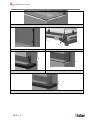
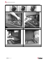
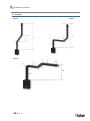
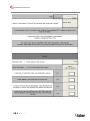
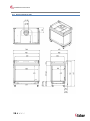
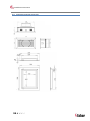
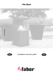
Duet Premium M 40011422-1441 Duet Premium M ENG Installation instructions 1<<<< 1.1 1.2 1.3 1.4 1.5 1.6 1.7 1.8 Installation instructions 2.1 a 2.1 b 2.1 c A C 2.2 2<<<< Installation instructions F F 2.3 H X X C 2.4 2.5 S T 3.1 3.2 R Q 3.3 3<<<< Installation instructions A 4<<<< 4.1 4.2 4.3 4.4 Installation instructions 5.0 5.1 5.2 5.3 5<<<< Installation instructions 1 Dear user Congratulations on purchasing your Faber product! A quality product, which provide you with the warmth and atmosphere for many years. Please read the user manual before using the fire. Should, despite the careful final checks, a malfunction occur, please contact your Faber dealer. Please note: The data of your fire is available in the user manual. 1.1 Introduction Only have the appliance installed by a qualified installer according to the gas safety regulations. Read this installation manual properly. 1.2 Please check Check the fire for transport damage and report any damage immediately to your dealer. 1.3 3 Installation requirements 3.1 3.2 This Declaration is invalid, if without the written permission of Glen Dimplex Benelux: Changes are made to the appliance. The fire is connected to other exhaust materials than specified. Safety instructions Fire CE Declaration Glen Dimplex Benelux certifies that this Faber fire complies with the essential requirements of the gas appliances directive. Product: gas room heater Model: Duet Premium M Applicable EC directives: 90/396/EEC Harmonised standards applied: NEN-EN-613 NEN-EN-613/A1 2 including the glass, can be very hot (over 100°C); exceptions to this are the bottom of the fire and the control elements. Do not place any combustible materials within 0.5 m of the radiation area of the fire. Light the fire for the first time and run for several hours on the highest setting, so that the paint can cure. Provide adequate ventilation, so that any fumes can disperse ; we recommend vacating the room during this process Please note Through the natural air circulation of the fire moisture and uncured volatile components from paint, building materials and carpeted floors, etc. are attracted. These parts can settle as soot on cold surfaces. Therefore do not light the fire shortly after installation. The unit must be installed and checked every year according to these instructions and the applicable national and local regulations. Ensure that the data on the type label matches the local gas type and pressure. The settings and the construction of the fire must not be changed! Do not place extra imitation wood or other smouldering material on the burner or in the combustion chamber. The unit is for atmosphere and heating purposes. This means that all surfaces, 6<<<< 3.3 This device can be built into an existing or new chimney. For devices with flexible gas pipes the gas regulator block is mounted on the right side of the fire for transport reason. The gas regulator block with the receiver and the I.T.C. must be placed directly behind a service door. (Fig. 1.5) False chimney breast or other structure The False chimney should be of noncombustible material. The space above the fire should always be ventilated using the supplied grids or a similar alternative with minimal free passage of 200cm² per grid. Fluepipe and terminal requirements For the supply of the combustion air and the discharge of the combustion gases you should always use the Flue materials specified by Faber. Please note: Only when using these materials can Faber guarantee the safe and proper operation of the appliance. The outside of the concentric flue material can heat up to +/-150°C. Ensure, when penetrating a flammable wall or ceiling, Installation instructions 3.4 construction with proper insulation and protection. And ensure respective distance. Ensure for great discharge lengths that the concentric discharge material is supported every meter, so that the weight of the material is not supported by the fire. It is not permitted to start directly on the device with concentric cut down pipe material. The air supply could then possibly be closed. Terminals The combined supply and discharge can be done both via wall or through the roof or through an existing chimney. Please note: Verify if the position of the terminal meets the local regulations regarding ventilation openings. For proper functioning, the air supply and combustion gas discharge are not to be obstructed. The minimum distances are specified in Chapter 15. 3.4.1 C11, Wall terminal. For a facade or wall outlet use a wall terminal. (Fig. 5.0 C11) Depending on the calculation this can be a diameter of 130/200mm or 100/150mm. 3.4.2 C31, Roof terminal. For a flat or pits roof outlet use a long roof outlet with a diameter of 100/150mm (Fig. 5 0 C31) 3.4.3 C91, Existing chimney. For an existing chimney use the short chimney outlet with a diameter of 100/150mm (Fig.5.0 C91). 4 Preparation and installation instructions 4.1 The gas connection must comply with the applicable local standards. We advise using a Ø 15mm gas connection directly from the gas meter to the appliance, with a shutoff valve in the proximity of the appliance, which must always be freely accessible. Position the gas connection so that it is easily accessible at all times for service, and that the burner unit can be disassembled. 4.2 Electrical connection The power supply must comply with the applicable local standards. A 6 Volt adapter is used. For this, a wall socket 230VAC/50Hz must be installed near the fire. 4.3 4.4 Preparing the fire Remove the fire from its packaging. Ensure that the gas supply pipes under the appliance are not damaged. Remove frame and glass and take the packaged parts from the fire. Store frame and glass in a safe place. Prepare the gas connection on the regulator Positioning the fire Take the installation requirements into account (see Chapter 3). 4.4.1 In this case the existing chimney acts as air inlet an inserted flexible stainless steel pipe discharges the flue gas. The top and the bottom should be airtight. Depending on the calculated outlet diameter, use a flexible stainless steel tube of Ø 100mm or Ø 130mm with CE marking for 600°C. Please note: The minimum chimney diameter for a 130mm flexible stainless steel pipe must 200 x 200mm. And for a 100mm flexible stainless steel pipe 150x150mm. Gas connection Standing on the floor Place the unit in the right position and set the height with the leg levellers. Height adjustment and levelling of the fire (Fig. 1.4). Rough height adjustment: with the extendable leg, or with the long legs supplied. Fine adjustment: with the adjustable feet. 4.4.2 Suspended from the wall The appliance can be mounted suspended from the wall with the use of the suspension bracket and the Rawlplugs supplied (Fig.1.3). 7<<<< Installation instructions These mounting materials are exclusively intended for use on walls constructed of brick or concrete. For walls built of other materials, such as hollow bricks, consult a professional expert. 4.5 For installation and finishing the following points are of interest: A = Fixing points (Fig. 2.2). B = Mouldings (Fig. 2.2). C = Spacer (Fig. 2.5) Installing the Flue materials D, F and H (Fig. 2.2, 2.3 and 2.5). 4.6 When penetrating a wall or ceiling the opening must be at least 5mm larger than the diameter of the discharge material. Horizontal sections should be installed with a slope towards the fire (3 degrees). Build the system from the fire. If this is not possible you can make use of an extendable adapter section. For truing up the exhaust system use the ½ meter pipe, which can be shortened and ensure that the inner pipe is always 2cm longer than the outer pipe. Parts, which are shortened, must be secured with a self-tapping screw Wall and roof terminals can also be cut. Do not insulate but ventilate built-in flue material. (approx. 100cm2). Constructing the false chimney Please note: Ensure that the fire is not load-bearing with regard to the false chimney breast . (See the dimensional drawing Chapter 16.1). Pay special attention to the following points: 1. Check during work if the glass can be inserted and removed. 2. Check during work if the strips T (Fig. 3.2) or Q (Fig. 3.3) match. 4.6.4 Method 1 (Fig. 2.1a) Build the false chimney breast against the fixing points A, the mouldings B and the build-in frame D (Fig. 2.2). The installation must always allow for installing and removing the glass! Take into account the thickness of the finish! If possible, carry out a performance test on the fire before finally finishing the installation. Mouldings B has to be in line (F Fig. 2.3) with the top of the glass slot H.(Fig. 2.5) 4.6.1 Do not use moulding B as a supporting structure (fig. 2.5) Minimum false chimney size and distance to combustible materials Construct the false chimney of non-combustible material in combination with metal profiles or of masonry/concrete blocks. Always use a lintel or reinforcing bars while bricking the outlet. They should not be placed directly on the fire. 4.6.2 Ventilation The ventilation must comply with the applicable local standards. Correct ventilation prevents a too high temperature of the gas regulator block and its electronics and also limits the temperature of the convection air. Therefore plan for outlet of grills and a ventilating control hatch with a minimum 2 free passage of 200cm per grid or a similar alternative. Place above the grates a screen plate made of noncombustible material. ( Fig. 1.2A) 4.6.3 Installation and finishing 8<<<< Remove the fixing points (A) on the side wall before the outlet wall is finally finished! (Fig. 2.4). 4.6.5 Method 2 (Fig. 2.1b) Process see Chapter 4.6.4 4.6.6 Method 3 (Fig. 2.1c) Remove the moulding B (Fig. 2.2). To ensure the air-tightness of the unit the screws must be replaced. The base X (Fig. 2.5) must be 2mm clear of the spacer C (Fig. 2.5) and 4mm above the glass slot H of the unit (Fig. 2.5). This will allow the Strip Q (Fig. 3.3) to be on the same level as the base. 4.6.7 Mounting the Solid cover strips (Fig. 3.1, 3.2 and 3.3) First, place the bottom strip (T or Q) Then place the left and right strips (S) (these are fixed by the adjustable magnetic snappers) Installation instructions 6.2 Remove the bottom strip (Q) using the supplied magnetic knob (R, Fig. 3.3). 5 Removing the glass 5.1 removing the front glass Remove the solid covers trips see Chapter 4.6.7 Place the suction cups on the glass. Draw the sealing cord from the slot. (Fig.4.1). Slide the glass to the top so that the bottom is released from the slot. Now pull the glass out and gradually down. (Fig. 4.2). 5.2 removing the glass from the side It is not necessary to take out the glass on the side for placing the log set or for maintenance. First remove the front glass. Remove the log set, bottom plate and burner. (Fig. 4.3) Place the suction cups on the glass Remove the sealing cord from the slot. Remove the top of the glass gradually forward and up from the fire (Fig.4.4) Please note Replace the glass in reverse order. Clean all fingerprints from the glass, otherwise they will burn in once the fire is used. 6 Placing the decoration material It is not permitted to use other or to add more material in the combustion chamber. Keep the pilot light always free of decoration material! Do not place all decoration material at one time on the burner; the fabric parts can block it. 6.1 Log set Place some of the chips on the burner and on the bottom. Place the logs as specified. (Fig.5.1 or the included log set card) Divide the rest of the chips on the burner and on the bottom. Prevent a thick layer on the burner; this adversely affects the flame pattern. 9<<<< Glow wire The “glow wire” gives a decorative glow effect. Pull the wool well apart and place tufts in different places on the burner. Please note: Do not use the glow wire near the pilot flame! This can cause a short circuit in the ignition system! 6.3 Pebbles or Grey stone Place the pebbles or grey stones on the burner and on the bottom. (Fig. 5.2 and 5.3 or the included log set card). Prevent a double layer; this adversely affects the flame pattern. Replace the glass and check the flame pattern. Start the fire as described in the user manual. Check if the flame distribution is good. Move the chips if necessary, until a good flame distribution is achieved. 7 Checking the installation 7.1 Checking the main burner ignition, pilot flame Ignite the fire as described in the user manual. Check that the pilot flame is well above the main burner and not covered by chips. Check the ignition of the main burner on full and small setting. (ignition must be smooth and quiet). 7.2 Checking for gas leaks Check with a gas leak finder or spray all connections and pipes for gas leakage. 7.3 Checking the burner pressure and primary pressure Check that the burner pressure and primary pressure match the information listed in the manual, Chapter 14 Technical specifications. Measuring the primary pressure: Close the shutoff valve. Turn measuring nipple B (Fig. 1.6) some turns open and connect a measuring hose to the gas regulator. Installation instructions Take this measurement at highest setting of the fire and when the fire is set to pilot light. Do not connect the unit if the pressure is too high. Measuring the burner pressure: Check the burner pressure only with proper primary pressure. Turn measuring nipple A (Fig. 1.6) some turns open and connect a measuring hose to the gas regulator. The pressure must correspond to the value indicated in the technical specifications of this manual. In case of deviation contact the manufacturer. Please note: Close all pressure measuring nipples and check for gas leakage. CO2 is 4% and CO is 400ppm, measured at the highest point If the ratio is greater than 1:100 or exhaust gases are measured in the supply air, then also check above points. 8 Instructions for client 7.4 Checking the flame image Let the fire burn for at least 20 minutes at highest setting and check the flame for: 1. Flame distribution 2. Colour of the flames If one or both points are not acceptable then check: The log set layout and/or the amount of chips on the burner. The pipe connections for leaks (in case of blue flames). Whether the correct Restrictor is fitted. The outlet. o Wall terminal right side up o Roof terminal on the right position o If the maximum horizontal flue lengths is not exceeded. 7.5 Flue gas analyzer If you are in possession of a CO/CO2 flue gas analyzer, then it is possible to check the supply air and the combustion gases. There are two measuring pipes at the front of the fire between the mounting frame and the glass (Fig. 1.7 A and B). The ratio CO2 and CO must not be greater than 1:100 Example: 10 < < < < Recommend that the unit should be checked annually by a qualified specialist to ensure the safe use and to guarantee a long service life. Give advice and instructions on care and cleaning of the glass. Highlight the danger of burnt-in fingerprints. Instruct the customer on the operation of the unit and the remote control, including replacing the batteries and setting the receiver. Handover to customer: o Installation instructions o User manual o ITC operating instructions o Log set instruction card o Suction Cups o Magnetic snapper 9 Annual maintenance 9.1 Checking and cleaning: Check and clean if necessary after verification: o The pilot light o The burner; for LPG flat burner the ceramic burner top. 9.2 o The combustion chamber o The glass o The ceramic logs for breakages. o The flue system. Replace, if necessary: o Chips/Embers/ Glow wire Cleaning the glass Most deposits can be removed with a dry cloth. Clean the glass with a ceramic hob cleaner. Please note: Avoid fingerprints on the glass. These are no longer removable after they are burnt in! Now carry out the checks described in Chapter 7 “Checking after installation”. Installation instructions 10 Conversion to other gas type The conversion to a different gas type may only be performed by a qualified installer/dealer. 10.1 Conversion from natural gas to propane (or vice versa) This can only be done by replacing the burner. To do so, please contact your dealer. Specify with your order always the type and serial number of the device. Total Vertical Height (TVH) TVH is the difference in height measured from the top of the fire to the outlet; it can be measured or determined from the building plan. For clarification see the TVH indication in the drawings. (Fig. 12.1, 12.2 and 12.3: TVH) Total Horizontal Length (THL) THL is the Total Horizontal Length and consists of elbows and pipes which are entirely in the horizontal plane. Elbows I, K and Q and the elements H, J, L, M, P and R (Fig. 12.2 and 12.3). Horizontal length The horizontal length consists of the elements H, J, L, M, P and R (Fig. 12.2 end 12.3). Elbows 90° in the horizontal plane Horizontal bends are bends which are entirely in the horizontal plane (Fig. 12.1, 12.2 and 12.3 I, K and Q). 11 Flue calculation A simple way to calculate whether the exhaust configuration is possible in combination with your fire, use the free “Faber Flue App” and download from: Bends 45° or 30° in the horizontal plane Horizontal bends are bends which are entirely in the horizontal plane Bends Elbows 90° vertical to horizontal plane These are 90° elbows, which proceed from horizontal to vertical (Fig. 12.2 and 12.3 G, O and S) INTERNET: BlackBerry, Android, PC (with Google Chrome browser) APP store: iPhone, iPad and Mac. Google Play: Android smartphones and Android tablets. Alternatively use the exhaust calculation table. (see chapter 13). The alternatives of outlet lengths and any restrictors are set out in the restrictor table. In the table we work with Start Length (STL) Total Vertical Height (TVH) and Total Horizontal Length (THL). Start Length (STL) This is the first part that is placed on the fire and represents a certain value (Fig. 12.1, 12.2 and 12.3 A, N, F). This value is in the top row of the table (see table). 11 < < < < Bends 45° or 30 °vertical to horizontal plane These are 30° or 45° bends with a vertical offset of less than 45° (Fig.12.1 B and D). Pipes under a tilt angle: These are pipes which are vertically ascending at an angle of 30° or 45°. (Fig. 12.1 C). Fill in only in combination with at least 2 x 30 or 45° bends in the vertical part. Table: See the table at the right vertical (TVH) and horizontal length (THL). For “x” and if the values are outside the table, then the combination is not allowed. Only then adjust the TVH or THL. If a value is indicated, check that the calculated STL value is not lower than indicated in the table. In this case STL must be adjusted. The found value indicates the width of the restrictor (“0” means no restrictor). Standard is a restrictor of 30mm installed. (Fig.1.8). Installation instructions 11.1 Table for pipe diameter 150/100mm Startlength (STL) Vertical (TVH) and Horizontal (THL) STL TVH STL 0.1 0.2 0.5 0.5 1 1 1 TVH 0 0,5 1 1,5 2 3 4 5 6 7 8 9 10 11 12 13 14 15 16 17 18 19 20 21 22 23 24 25 26 27 28 29 30 0 1 2 3 4 5 6 7 8 9 10 x x x x x x x x x x x x x x x x x x x x x x 0.00 0.00 0.00 x x x x x x x x 0.00 0.00 0.00 0.00 0.00 x x x x x x 30.00 0.00 0.00 0.00 0.00 0.00 0.00 x x x x 30.00 30.00 0.00 0.00 0.00 0.00 0.00 x x x x 40.00 30.00 30.00 0.00 0.00 0.00 0.00 x x x x 40.00 40.00 30.00 30.00 0.00 0.00 0.00 x x x x 50.00 40.00 40.00 30.00 30.00 0.00 0.00 x x x x 50.00 50.00 40.00 40.00 30.00 30.00 0.00 x x x x 50.00 50.00 50.00 40.00 40.00 30.00 0.00 x x x x 65.00 50.00 50.00 50.00 40.00 30.00 30.00 x x x x 65.00 65.00 50.00 50.00 40.00 30.00 30.00 x x x x 65.00 65.00 60.00 50.00 40.00 40.00 30.00 x x x x 65.00 65.00 60.00 50.00 50.00 40.00 30.00 x x x x 65.00 65.00 60.00 50.00 50.00 40.00 30.00 x x x x 65.00 65.00 60.00 50.00 50.00 40.00 30.00 x x x x 65.00 65.00 60.00 50.00 50.00 40.00 30.00 x x x x 65.00 65.00 60.00 50.00 50.00 40.00 30.00 x x x x 65.00 65.00 60.00 50.00 50.00 40.00 30.00 x x x x 65.00 65.00 60.00 50.00 50.00 40.00 30.00 x x x x 65.00 65.00 60.00 50.00 50.00 40.00 30.00 x x x x 65.00 65.00 60.00 50.00 50.00 40.00 30.00 x x x x 65.00 65.00 60.00 50.00 50.00 40.00 30.00 x x x x 65.00 65.00 60.00 50.00 50.00 40.00 30.00 x x x x 65.00 65.00 60.00 50.00 50.00 40.00 30.00 x x x x 65.00 65.00 60.00 50.00 50.00 40.00 30.00 x x x x 65.00 65.00 60.00 50.00 50.00 40.00 x x x x x 65.00 65.00 60.00 50.00 50.00 x x x x x x 65.00 65.00 60.00 50.00 x x x x x x x 65.00 65.00 60.00 x x x x x x x x 65.00 65.00 x x x x x x x x x 65.00 x x x x x x x x x x 12 < < < < THL THL Installation instructions 12 Example fig. 12.1 fig. 12.3 13 < < < < fig.12.2 Installation instructions 13 Calculation sheet 14 < < < < Installation instructions 15 < < < < Installation instructions 14 Technical data II2H3P II2H3+ II2H3P C11 C31 C91 C11 C31 C91 C11 C31 C91 G20 G30 G31 8.5 8.5 8.5 Efficiency class 2 2 2 NOx class 5 5 5 mbar 20 30 37 Gas rate at 15ºC and 1013 mbar l/h 909 268 349 Gas rate at 15ºC and 1013 mbar gr/h 670 660 Burner pressure at full mark mbar 11.5 20.2 28 Injector main burner mm 2x 390 100 Bin 100 Bin 120 Bui 120 Bui Reduced input restraint mm 1.8 1.3 1.3 Pilot assembly SIT145 SIT145 SIT145 Code Nr.36 Nr.23 Nr.23 150/100 150/100 150/100 Gas control valve GV60 GV60 GV60 Gas connection 3/8” 3/8” 3/8” 220 220 220 4x AA 4x AA 4x AA (1,5V) (1,5V) (1,5V) 9 9 9 Gascat. Type appliance Reference gas Input Nett inlet-pressure Diameter inlet / outlet kW mm Electrical connection V Batteries receiver V Batteries sender V 16 < < < < Installation instructions 15 Terminal position Please note: These rules apply only for the proper functioning of the unit, for ventilation and environmental protection you need to comply with the applicable rules as defined in the building regulations. Short roof terminal Only for existing Chimney connection Extension pipe over roof Location Distance mm D Under a gutter 500 E Under a roof edge 500 F Under a carport or balcony 500 G Vertical downpipe 300 H Inside and outside corners 500 J From wall surface to a wall outlet 1000 K Two gable outlets against over each other 1000 L Distance between two roof outlets 450 M Two roof outlets above each other on a pitched roof 1000 N Two gable outlets next to each other 1000 17 < < < < Installation instructions 16 Dimensional drawings 16.1 Duet Premium M left 18 < < < < Installation instructions 16.2 Duet Premium M right 19 < < < < Installation instructions 16.3 Ventilation grid and control door 20 < < < < Installation instructions 21 < < < < Installation instructions 22 < < < <