1
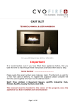
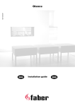
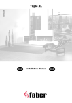
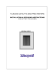
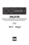
The Buzz 40010918-1013 ENG Installation and users guide ENG L 1.1 A 1.3 1.4 1.5 1.6 B 1<<<< L D 1.7 1.8 1 2.1 2.2 3.1 3.2 3.3 2<<<< L Table of contents 1 Introduction ......................................................................................... 4 2 Safety instructions.................................................................................. 4 2.1 3 Tips for the safe use of gas bottles ....................................................... 5 Installation requirements ......................................................................... 5 3.1 Placement of the Buzz ...................................................................... 5 3.2 Gas bottle and connection.................................................................. 5 4 Installation guide ................................................................................... 6 4.1 Contents ....................................................................................... 6 4.2 Installing the wheels......................................................................... 6 4.3 Installation gas connection ................................................................. 6 4.4 Removing front glass......................................................................... 7 4.5 Removing side glasses ....................................................................... 7 4.6 Placing the log set ........................................................................... 7 5 User manual ......................................................................................... 8 5.1 Ignition pilot light ............................................................................ 8 5.2 Igniting and regulating the main burner.................................................. 8 5.3 Extinguishing the pilot light. ............................................................... 8 6 Checking ............................................................................................. 9 6.1 Checking the ignition of the pilot burner, main burner................................ 9 6.2 Checking for gas leakage.................................................................... 9 6.3 Checking the flame image .................................................................. 9 7 Instruction client ................................................................................... 9 8 Annual maintenance .............................................................................. 10 8.1 Checking and cleaning:..................................................................... 10 8.2 Cleaning the glass ........................................................................... 10 9 Conversion to a different type of gas. (e.g. natural gas) .................................. 10 10 Technical specifics............................................................................. 11 11 Dimensions of the Buzz........................................................................ 12 3<<<< L 1 Introduction The Buzz is only intended for use outside the house. We urgently advise you to read this installation guide and user manual carefully. This appliance complies with the guidelines for European gas appliances (Gas Appliances Directive) and bears the CE mark. 2 Safety instructions. The Buzz should be installed and annually checked in accordance with these installation instructions and valid national and local Gas Safety (Installation and Use) Regulations . Check whether the data on the registration plate are in agreement with the local type of domestic gas and pressure. The installer is not permitted to change these adjustments or the construction of the Buzz! Do not place any additional imitation logs or glowing coals on the burner or in the combustion chamber. The first time the Buzz is switched on, burn it at the highest mark for some hours so that the lacquer coating will have an opportunity to set. The Buzz is only intended for use outside the house. Do not move the Buzz when it is in use. The Buzz has been designed for atmospheric and heating purposes. This means that the surface of the Buzz, including the glass, can become very hot (hotter than 100 °C). with the exception of the bottom of the Buzz and the controls. Do not place any combustible materials within a distance of 0.5 m. of the Buzz. When the Buzz is in use, it should not be exposed to rain. If the Buzz is not in use, cover it with the supplied cover. Let the Buzz cool down before placing the cover. If the Buzz is not in use for a considerable period of time, we advise you to store it inside. Note: damage to the lacquer will result in corrosion. 4<<<< L 2.1 Tips for the safe use of gas bottles Gas bottles should always be in an upright position, both while they are in use and during transportation. Never take a flame or a burning object near a gas bottle during the installation. Trace leaks by means of a brush with washing-up liquid and water, if bubbles are formed you will know there is a leak. Always use a pressure regulator between the bottle and the appliance. Replace the pressure regulator every 5 years. Only use approved gas connection hoses. Replace these every two years. Make sure there is always proper ventilation. Close the gas bottle if the appliance is not in use. Leave the filling of gas bottles in the hands of a certified gas cylinder filling station. 3 Installation requirements 3.1 Placement of the Buzz Place the Buzz outside on a flat and solid surface. Leave a free space of at least 0,5 m behind the Buzz for operating the controls. 3.2 Gas bottle and connection. Natural gas: The gas connection must comply with locally valid Guidelines. Use a stability chain. This will keep the Buzz from moving and prevent damage to the flexible hosing. Propane: The gas connection must comply with locally valid Guidelines. The gas bottle should be placed in the space underneath the burner. (See fig. 1.4) 5<<<< L 4 Installation guide 4.1 Contents Remove the rear wall plate and take out loose parts from the wrapping and check the Buzz for possible damages incurred during transport. (Report such damages to your supplier.) You will find : 1. Two PVC wheels with fasteners (see fig. 1.1) 2. Log set 3. Instruction manual 4. Suction pad (see fig. 2.1) 5. cover Not supplied : 1. A gas bottle with an approved gas hose with a ….. mbar pressure regulator. (See the Technical specifics for the correct pressure) 2. Security chain. 4.2 Installing the wheels Place the Buzz on a flat surface. Put the bolt with the washer through the whole of the wheel and tighten it with the black nut. Make sure that the nut is attached in such a way that there is minimal space on the wheel and that it can still turn. Attach the wheel to the Buzz and fix it with the lock nut. (See fig.1.1) 4.3 Installation gas connection Please take the installation requirements into account. (chapter 3) Propane bottle : Open the gas bottle space by removing the access plate (see fig. 1.3 ) Attach the gas hose to the pressure regulator by means of a hose clamp. Fix the other end in the same way to the threaded insert attached to the gas control tap. (see fig. 1.5 B) Remove the seal on the gas bottle. Connect the pressure regulator to the gas bottle. Check the entire gas connection for leakages. Now place the gas bottle into the space and fasten it with the web sling. (see fig. 1.4 A ) The gas bottle can be opened now. 6<<<< L Natural gas : Make sure you have an easily accessible gas tab outside the Buzz. Use a stability chain. This will keep the Buzz from moving and prevent damage to the flexible hosing, for assembling you can use the holes in the bottom plate. Disconnect the buzz if you plan to move the Buzz. 4.4 Removing front glass Place the suction pad on the front glass. (see fig. 2.1) Lift the glass and move the bottom side forwards towards you, the glass can now be removed from below. (see fig. 2.2) Replacing the glass is done in reverse order. Remove all Fingerprints from the glass, these will be burnt into the glass when the Buzz is in use. 4.5 Removing side glasses Is only necessary in case of damage. Remove the front glass. Remove the inside bottom plate (see fig. 3.1) Remove the burner unit (see fig. 1.6) Place the suction pad on the glass. (see fig. 2.1) Lift the glass, move the bottom of the glass inwards and remove the glass from below. (see fig.2.2) 4.6 Placing the log set Remove the front glass (see par. 4.3) Place the log set (see fig. 3.2 or the supplied log set instruction card) Replace the glass plate again. 7<<<< L 5 User manual The Buzz has been provided with a control valve with an inbuilt ignition for the pilot light. The level of the flame can be adjusted accordingly. The control panel is located at the back behind the access plate. (see fig. 1.4) 5.1 Ignition pilot light turn the knob of the control valve in the OFF-position Open the gas bottle. Press the knob and turn it to the position. You will hear a click and a spark will appear which should ignite the pilot light. If the pilot does not light then repeat procedure Keep pressing the knob down for about ten seconds after the ignition of the pilot light. Let go of the knob and check whether the pilot light remains alight. 5.2 Igniting and regulating the main burner. Turn the knob to the left, the main burner will ignite and the level of the flame can be continuously adjusted now. By turning the knob to the position, the main burner will be extinguished and the pilot light will remain alight. 5.3 Extinguishing the pilot light. Turn the knob to the OFF position, and the pilot light will be extinguished. Turn off the tap on the gas bottle. 8<<<< L 6 Checking 6.1 Checking the ignition of the pilot burner, main burner. Ignite the pilot burner as described in chapter 5 Check the ignition of the main burner at full mark and low mark (the ignition should proceed smoothly). 6.2 Checking for gas leakage. Check all connections and attachments for possible gas leaks. This can be done with the help of: a small brush with washing-up liquid and water a gas leak spray a gas leak detector. Dry off the checked connections after the check-up. 6.3 Checking the flame image Let the Buzz burn at full mark and then check the flame image Flame distribution (see fig. 3.3) If the flame image is not consistent, then check: The positioning of the log set. The primary air intake of the burner for blockages. (see fig. 1.7 C ) 7 Instruction client Recommend that the appliance be serviced annually by a Gas Safe registered gas fitter in order to guarantee a safe use and a long lifespan. Point out the lifespan of the gas hose and the pressure regulator to the client. Advise and instruct the client about maintenance and cleaning of the glass. Emphasize the risk of burning in fingerprints. Instruct the client about the operation of the appliance. Hand over to the client: 9<<<< o Installation guide o Log set instruction card o Suction lifter L 8 Annual maintenance We recommend the cleaning of the pilot light and the main burner unit after retrieval of the appliance from winter storage before it is used again. 8.1 Checking and cleaning: Check and clean if necessary after check-up: o The main burner, especially for the primary air intake (see fig.1.7 C ) o The pilot light, especially for the primary air intake (see fig.1.8 D ) o The glass o The log set for possible fractures o Gas hose and pressure regulator. 8.2 Cleaning the glass Most deposits can be removed by means of a dry cloth. You can use ceramic hob cleaner to clean the glass. Note: prevent fingerprints on the glass. These will be burned into it once the appliance is used and cannot be removed. Now carry-out the check-up as described in chapter 6 “Checking”. 9 Conversion to a different type of gas. (e.g. natural gas) This can only be done by replacing the correct burner unit. Please get in touch with your supplier for this. Always mention the type and serial number of the appliance when giving the order. 10 < < < < L 10 Technical specifics Gascat. II2H3P II2H3P Type appliance A A Reference gas G31 G20 Input Nett kW 9.3 8 inlet-pressure mbar 30 20 Gas rate at 15ºC and 1013 mbar l/h 374 823 Gas rate at 15ºC and 1013 mbar gr/h 700 - Burner pressure at full mark mbar 27.5 8.5 Injector main burner 1.6 2.7 Reduced input restraint ajustible ajustible Pilot assembly OP 9222 OP 9030 Code - - Seagas Gas control valve A7 Gas connection Electrical connection 11 < < < < V Seagas A7 ø8mm ø8mm - - L 11 Dimensions of the Buzz 12 < < < < L 13 < < < < L 14 < < < <