1
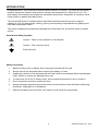
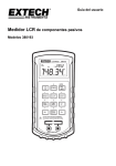
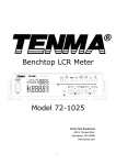
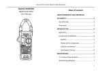
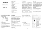
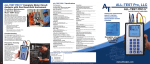
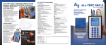
User's Guide Passive Component LCR Meter Model 380193 LCR Meter 380193 APO AUTO D PAL c 1kHz µ -0 ENTER PAL SER FREQ 1 2 3 RANGE L/C/R Q/D/R 4 5 6 MIN MAX SET 7 8 9 REL Hi / Lo LIMITS TOL >2sec HOLD DO NOT APPLY VOLTAGE TO TERMINALS DISCHARGE CAPACITOR BEFORE TESTING + AUTO-POWER OFF – F INTRODUCTION Congratulations on your purchase of Extech's Model 380193 LCR meter. This meter will accurately measure capacitors, inductors and resistors using the test frequencies of 120Hz and 1 kHz. The dual display will simultaneously display the associated quality factor, dissipation or resistance value using a series or parallel equivalent circuit. The included RS-232c PC interface feature with Data Acquisition permits the user to capture readings to a PC for data storage, viewing, printing, and exporting to spreadsheet for graphing and other data manipulation tasks. This meter is shipped fully tested and calibrated and, with proper use, will provide years of reliable service. International Safety Symbols ! Caution ! Refer to the explanation in this Manual Caution ! Risk of electric shock Earth (Ground) Safety Precautions 1. Make sure any covers or battery doors are properly closed and secured. 2. Always remove the test leads before replacing the battery or fuses. 3. Inspect the condition of the test leads and the meter itself for any damage before operating the meter. Repair or replace any damage before use. 4. To reduce the risk of fire or electric shock, do not expose this product to rain or moisture. 5. Do not exceed the maximum rated input limits. 6. Always discharge capacitors and remove power from the device under test before performing Inductance, Capacitance, or Resistance. 7. Remove the battery from the meter if the meter is to be stored for long periods. 2 380193-en-GB_V2.5 4/15 METER DESCRIPTION 6 1. Q/D/R display 2. L/C/R display 3. Keypad 4. 7 Input jacks 6. External power input 1kHz µ 3 -0 ENTER FREQ PAL SER 1 RANGE 7. Protective holster 4 >2sec HOLD 8. 380193 D PAL c 2 Test fixture 5. LCR Meter APO AUTO Battery compartment (rear) 2 3 L/C/R Q/D/R 5 6 MIN MAX SET 7 8 9 REL Hi / Lo LIMITS TOL DO NOT APPL YVOLTAGETOTERMINALS DISCHARGE CAP ACITOR BEFORE TESTING 4 + – AUTO-POWER OFF 1 F 8 5 Display Symbols and Annunciators APO Auto Power Off 1KHz 1kHz test frequency R Recording mode active 120Hz 120Hz test frequency MAX Maximum reading M Mega (10 ) MIN Minimum reading K kilo (10 ) AVG Average reading p pico (10 ) AUTO AutoRanging active n nano (10 ) H Data hold active micro (10 ) SET SET mode m milli (10 ) TOL Tolerance mode H Henry (inductance units) PAL Parallel equivalent circuit F Farad (capacitance units SER Series equivalent circuit Ohms (resistance units) D Dissipation factor Upper limit Q Quality factor Lower limit R Resistance Relative mode L Inductance Low battery C Capacitance % 3 6 3 -12 -9 -6 -3 Tolerance (percentage) 380193-en-GB_V2.5 4/15 OPERATING INSTRUCTIONS CAUTION: Measuring a DUT (device under test) in a live circuit will produce false readings and may damage the meter. Always remove power and isolate the component from the circuit to obtain an accurate reading. CAUTION: Do not apply voltage to the input terminals. Discharge capacitors before testing Note: Measurement considerations for resistance <0.5 ohms. 1. Use positive contact alligator clips. 2. Perform a SHORT calibration zero to remove stray impedances. 3. Clean the DUT leads / contacts of oxidation or film to minimize contact resistance. Power 1. Press the power key to turn the meter on or off 2. Auto-Power OFF (APO) If the keypad is inactive for 10 minutes, the meter will automatically shut down. If this occurs, press the key to resume operation. 3. Auto-Power Off disable. To disable the auto-power off feature, from the off position, press and hold the power on key until “APO OFF” appears in the display. Auto-Power Off will also be disabled if the MIN MAX record mode is used or if the meter is powered by an external power supply. Frequency Selection Press the FREQ key to select either 120Hz or 1kHz as the test frequency. The frequency selected appears in the display. Generally, 120Hz will be used for large electrolytic capacitors and 1kHz used for most other tests. Parallel/Series Selection Press the PAL SER key to select either a parallel (PAL) or series (SER) equivalent circuit. The selected mode will appears as “SER” or “PAL” in the display. This mode defines the R loss of an inductor or capacitor as a series loss or a parallel loss. Generally, high impedances are measured in the parallel mode and low impedances are measured in the series mode. Range Selection The meter turns on in the autoranging mode with “AUTO” indicated in the display. Press the RANGE key and the “AUTO” indicator will disappear. Each press of the RANGE key will now step through and hold the available ranges for the parameter selected. To exit the manual range mode, press and hold the RANGE key for 2 seconds. 4 380193-en-GB_V2.5 4/15 Inductance, Capacitance, Resistance Selection The L/C/R key selects the primary parameter measurement function. Each press of the key will select either inductance (L), capacitance (C) or resistance (R) along with the proper units of H (henries), F (farads) or (ohms) in the main large display. Quality, Dissipation, Resistance Selection The Q/D/R key selects the secondary parameter measurement function. Each press of the key will select either the quality (Q) or dissipation (D) indicators or resistance () units in the small secondary display. Hold and Backlight Selection The HOLD >2sec key selects the Hold feature and also enables the display backlight. Press the key and the H indicator will appear in the display and the last reading will “freeze” in the display. Press the key again and the reading will begin to update again. Press and Hold the key for 2 seconds and the display backlight will turn-on. To extinguish the backlight, press and hold the key again for 2 seconds or wait 1 minute for it to automatically disable. Minimum, Maximum and Average Selection The MAX MIN key selects the recording function. Press the key and the “R“ indicator will appear in the display and the meter will begin recording the minimum, maximum and average measured values. When this mode is entered, the auto power off and the function keys are disabled. Max-Min operation 1. Set all the function parameters for the test. 2. Press the MAX MIN key. The “R“ indicator will appear and a “beep” will sound after approximately six seconds. Two “beeps” will sound every time the max or min is updated. 3. Press the MAX MIN key. The “MAX” indicator and the maximum recorded value will appear in the display 4. Press the MAX MIN key. The “MIN” indicator and the minimum recorded value will appear in the display 5. Press the MAX MIN key. The “MAX - MIN” indicator and the difference between the maximum - minimum value will appear in the display 6. Press the MAX MIN key. The “AVG” indicator and the average of the recorded values will appear in the display. 7. Press and hold the MAX MIN key for 2 seconds to exit the mode. Notes: The average value is a true average and averages up to 3000 values. If the 3000 limit is exceeded, the AVG indicator will flash and no further averaging will take place. The max and min values will continue to update. If the HOLD key is pressed during min max recording, the recording is halted until the HOLD key is pressed again. Relative Mode The relative mode displays the difference between the measured value and the value of a stored reference. 1. Press the REL key to enter the Relative mode. 2. The value in the display when the REL key is pressed will become the stored reference value and the display will indicate zero or a value close to zero (since the measured value and the reference value are the same at this point). 3. All subsequent measurements will be displayed as a value relative to the stored value. 4. The reference value may also be a value that was stored into memory using the SET Relative procedure (see the Setting a Relative Reference paragraph). 5. To use the SET relative value, press the SET key while in the Relative mode. 6. To exit the Relative mode, press and hold the REL key for 2 seconds. 5 380193-en-GB_V2.5 4/15 Hi / Lo Limits Mode The Hi / Lo limits mode compares the measured value to the stored high and low limit values and gives an audible and visible indication if the measured value is outside the limits. See the setting Hi/Lo limits paragraph below to store the limits in memory. 1. Press the Hi/Lo LIMITS key to enter the mode. The display will briefly show the stored upper limit with the “ “ indicator and then the stored lower limit with the “ “ indicator before displaying the measured value. 2. The meter will sound an audible tone and blink the upper or lower limit indicator if the measured value is outside the limits. 3. The meter will ignore an “OL” overload reading. 4. Press the Hi/Lo LIMITS key to exit the mode. % Tolerance Mode The % Tolerance Limits mode compares the measured value to a % high and low limit based on a stored reference value and gives an audible and visible indication if the measured value is outside the limits. Any % limit can be entered in the SET % Limit mode (see paragraph below) or standard 1%, 5%, 10% and 20% symmetrical limits can be selected directly in the % Tolerance mode. 1. Press the TOL key to enter the mode. The display will briefly show the stored reference value in the main display and the small display will indicate the % difference between the measured value and the reference value. See the SET % Limit paragraph to change the reference value. 2. Press the TOL key to step through and select the 1, 5, 10 or 20% settings. The selected % will briefly appear in the small display. 3. Previously stored user defined % limits are accessed by pressing the SET key. 4. The meter will sound an audible tone and blink the upper or lower limit indicator if the measured value is outside the limits. 5. Press and hold the TOL key for 2 seconds to exit the mode. Set Limits and Open/Short Calibration Selection The SET key is used to; 1. Set Hi/Lo limits, 2. Set % limits, 3. Set Tolerance reference value and 4. Perform the Open / Short calibration. The SET mode can only be activated if no other function is active. Entering the SET mode 1. Power ON and press the SET key. 2. The display will clear, “SEt“ will appear in the small display and a flashing TOL and flashing indicators will appear in the display. 3. The 5 keys that are now active are; Power, SET, REL, Hi/Lo, and TOL Open and Short Calibration The Open and Short function removes stray parallel and series fixture impedances from the measured value. This feature improves accuracy for very high or low impedances. (Note: Remove any leads from the meter during this procedure. Leaving them connected will add impedance to the circuit causing the calibration to fail indicated by OUT UAL appearing on the display.) 1. Press the SET key 2 times and the display will indicate “CAL OPEn”. 2. Remove any devices or test leads from the input terminals and press “ENTER” (PAL SER). After several seconds the calibration will complete and display “CAL SHrt”. 3. Short the input terminals and press “ENTER” (PAL SER). After several seconds the calibration will complete and the meter will return to normal operation. 4. Press the “SET” to bypass either the open or short calibration. 6 380193-en-GB_V2.5 4/15 Setting Absolute Hi/Lo Limits The Hi/Lo limits set allows the user to enter an upper and lower limit value into memory for comparison to the measured value. 1. Press the SET key and then the Hi / Lo LIMITS key. The upper limit “ “ indicator will flash and the previously stored upper limit will appear with the first digit flashing. 2. Set the value of the flashing digit by pressing the appropriate numeric key. The adjustment selection will then proceed through each digit from left to right. 3. Press the - 0 key after the last digit is set to change the value of the sign to negative or positive. 4. Press the “ENTER” key to store the value and continue on to the lower limit adjustment. 5. The lower limit “ “ indicator will flash and the previously stored lower limit will appear. 6. Adjust the limits as described for the upper limit and press the “ENTER” key when complete. Setting % Tolerance Limits The % tolerance set allows the user to enter an upper and lower percentage limit into memory for comparison of the measured value to a reference value. 1. Press the SET key and then the TOL key. The “TOL” indicator will flash and the previously stored reference will appear with the first digit flashing. 2. To adjust the reference, set the value of the flashing digit by pressing the appropriate numeric key. The adjustment selection will then proceed through each digit from left to right. 3. Press the “ENTER” key to store the value and continue on to the % upper limit adjustment. The upper limit “ “ indicator will flash and the previously stored upper % limit will appear. 4. Adjust the % limit as described for the reference value and press the “ENTER” key when complete. The lower limit “ “ indicator will flash and the previously stored lower % limit will appear. 5. Adjust the lower % limit and press “ENTER” when complete. Setting a Relative Reference The relative set allows the user to store a relative reference value into memory for later use in the REL mode. 1. Press the SET key and then the REL key. The “ ” indicator will flash and the previously stored reference will appear with the first digit flashing. 2. To adjust the reference, set the value of the flashing digit by pressing the appropriate numeric key. The adjustment selection will then proceed through each digit from left to right. 3. Press the - 0 key after the last digit is set to change the value of the sign to negative or positive. 4. Press the “ENTER” key to store the reference value. 7 380193-en-GB_V2.5 4/15 PC INTERFACE TM The Model 380193 LCR Meter includes a PC interface feature for use with the supplied Windows software. The interface allows the user to: View measurement data in real time on the PC Save, Print, and Export measurement data. Set standard and high / low limits for data analysis Generate calibration reports in spreadsheet format Plot SPC (statistical process control) analyses TM Database compatibility (supports ODBC) for use with: SQL server, Access , and other database utilities Instructions for use of the PC interface are included on the supplied Program Disk and are beyond the scope of this operation manual. For complete details and instructions refer to the HELP file on the supplied Program Disk. You, as the end user, are legally bound (EU Battery ordinance) to return all used batteries, disposal in the household garbage is prohibited! You can hand over your used batteries / accumulators at collection points in your community or wherever batteries / accumulators are sold! Disposal: Follow the valid legal stipulations in respect of the disposal of the device at the end of its lifecycle 8 380193-en-GB_V2.5 4/15 SPECIFICATIONS Capacitance @ 120Hz Range Cx accuracy DF accuracy Note 9.999mF ±(5.0% rdg + 5d) ±(10%rdg + 100/Cx + 5d) after short cal (DF<0.1) (DF<0.1) 1999.9μF ±(1.0% rdg + 5d) ±(2%rdg + 100/Cx + 5d) after short cal (DF<0.1) (DF<0.1) 199.99μF ±(0.7% rdg + 3d) ±(0.7%rdg + 100/Cx + 5d) (DF<0.5) (DF<0.1) 19.999μF ±(0.7% rdg + 3d) ±(0.7%rdg + 100/Cx + 5d) (DF<0.5) (DF<0.1) 1999.9nF ±(0.7% rdg + 3d) ±(0.7%rdg + 100/Cx + 5d) (DF<0.5) (DF<0.1) 199.99nF ±(0.7% rdg + 5d) ±(0.7%rdg + 100/Cx + 5d) after open cal (DF<0.5) (DF<0.5) 19.999nF ±(1.0% rdg + 5d) ±(2.0%rdg + 100/Cx + 5d) after open cal (DF<0.1) (DF<0.1) Capacitance @ 1kHz Range Cx accuracy DF accuracy Note 999.9μF ±(5.0% rdg + 5d) ±(10%rdg + 100/Cx + 5d) after short cal (DF<0.1) (DF<0.1) 199.99μF ±(1.0% rdg + 3d) ±(2.0%rdg + 100/Cx + 5d) after short cal (DF<0.5) (DF<0.5) 19.999μF ±(0.7% rdg + 3d) ±(0.7%rdg + 100/Cx + 5d) (DF<0.5) (DF<0.1) 1999.9nF ±(0.7% rdg + 3d) ±(0.7%rdg + 100/Cx + 5d) (DF<0.5) (DF<0.1) 199.99nF ±(0.7% rdg + 5d) ±(0.7%rdg + 100/Cx + 5d) (DF<0.5) (DF<0.1) 19.999nF ±(0.7% rdg + 5d) ±(0.7%rdg + 100/Cx + 5d) after open cal (DF<0.1) (DF<0.1) 1999.9pF ±(1.0% rdg + 5d) ±(2.0%rdg + 100/Cx + 5d) after open cal (DF<0.1) (DF<0.1) Inductance @ 120Hz Range Lx accuracy (DF<0.5) DF accuracy (DF<0.5) Note 10000H Not specified Not specified 1999.9H ±(1.0%rdg + Lx/10000 + 5d) ±(2.0%rdg + 100/Lx + 5d) after open cal 199.99H ±(0.7%rdg + Lx/10000 + 5d) ±(1.2%rdg + 100/Lx + 5d) 19.999H ±(0.7%rdg + Lx/10000 + 5d) ±(1.2%rdg + 100/Lx + 5d) 1999.9mH ±(0.7%rdg + Lx/10000 + 5d) ±(1.2%rdg + 100/Lx + 5d) 199.99mH ±(1.0%rdg + Lx/10000 + 5d) ±(3.0%rdg + 100/Lx + 5d) after short cal 19.999mH ±(2.0%rdg + Lx/10000 + 5d) ±(10%rdg + 100/Lx + 5d) after short cal Inductance @ 1kHz Range Lx accuracy (DF<0.5) DF accuracy (DF<0.5) Note 1999.9H Not specified Not specified 199.99H ±(1.0%rdg + Lx/10000 + 5d) ±(1.2%rdg + 100/Lx + 5d) after open cal 19.999H ±(0.7%rdg + Lx/10000 + 5d) ±(1.2%rdg + 100/Lx + 5d) 1999.9mH ±(0.7%rdg + Lx/10000 + 5d) ±(1.2%rdg + 100/Lx + 5d) 199.99mH ±(0.7%rdg + Lx/10000 + 5d) ±(1.2%rdg + 100/Lx + 5d) 19.999mH ±(1.2%rdg + Lx/10000 + 5d) ±(5.0%rdg + 100/Lx + 5d) after short cal 1999.9μH ±(2.0%rdg + Lx/10000 + 5d) ±(10%rdg + 100/Lx + 5d) after short cal Note: Where Lx or Cx is the the C or L reading in the display without range indication. i.e. For a reading of 18.888, use 18888 as the factor. 9 380193-en-GB_V2.5 4/15 Resistance Range accuracy (1kHz & 120Hz) Note ±(2.0%rdg + 8d) after open cal* 10.000M ±(0.5%rdg + 5d) after open cal* 1.9999M ±(0.5%rdg + 3d) 199.99k ±(0.5%rdg + 3d) 19.999k ±(0.5%rdg + 3d) 1.9999k ±(0.8%rdg + 5d) after short cal 199.99 ±(1.2%rdg + 8d) after short cal 0.020 to 19.999 *Note: For resistance readings above 1MΩ, series and parallel impedances may affect readings (especially at 1kHz). This effect is often noticed on decade resistance boxes where the AC measured value can vary from the DC calibrated value. Use fixed value low inductance resistors (film or equivalent) for high resistance calibration or certification. Note: In the 20 range, effective readings must be over 20 counts. Test Frequency (accuracy) 122.88Hz (±4Hz) and 1kHz (±4Hz) Display: Dual 4 ½ digit backlit LCD Overload indication: “OL” Low battery indication: Measurement rate: One time per second Auto-power off: After 10 minutes of inactivity Operating environment: 0 C to 50 C (32 F to 122 F), < 80% RH Storage environment: -20 C to 60 C (14 F to 140 F), < 80% RH, battery removed o o o o o o o o Power: 9V battery or optional external 12V-15V @ 50mA (approx.) Fuse 0.1A/250V fast blow Dimensions: 19.2x9.1x5.25cm (7.56x3.6x2.1”) Weight: 365g (12.9oz) Copyright © 2011 ‐ 2015 FLIR Systems, Inc. All rights reserved including the right of reproduction in whole or in part in any form www.extech.com 10 380193-en-GB_V2.5 4/15