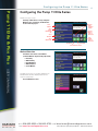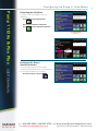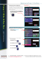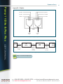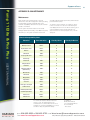
1
USER’S MANUA L
Harvard Apparatus Pump 11 Elite
& Pump 11 Pico Plus Elite Series
Publication 5420-002 Rev B
phone
email
www.h arvar d ap p a ra tu s .c o m
Pump 11 Elite &
Pump 11 Pico Plus Elite
800.272.2775
[email protected]
Table of Contents
2
Pump 11 Elite & Pico Plus
Table of Contents
SUBJECT
PAGE NO.
General Information ................................................................................................6
Safety Information..................................................................................................6
Warranty and Repair Information ..........................................................................7
Manual Description ....................................................................................7
Warranty ......................................................................................................7
Repair Facilities and Parts ..........................................................................7
Serial Numbers............................................................................................7
Calibrations..................................................................................................7
Specifications ........................................................................................................8
Product Overview....................................................................................................9
Pump Models ......................................................................................................10
Pump 11 Elite Series Touch Screen Button Reference........................................11
Selecting an Item from a Menu List ....................................................................12
Messages ............................................................................................................12
Entering Values ....................................................................................................12
USER’S MANUAL
Operating Instructions..........................................................................................13
Power Connections ..............................................................................................13
Syringe Loading....................................................................................................14
Configuring the Pump 11 Elite Series..................................................................15
Method Selection ................................................................................................15
Syringe Selection..................................................................................................16
Flow Rate Selection ............................................................................................17
Target Volume/Time Selection ..............................................................................18
Previewing the Quick Start ..................................................................................19
Configuring the Pump’s General Parameters ......................................................19
Setting the Audible Alarms ..................................................................................20
For Near End of Run Selection ..................................................................21
For a Custom ............................................................................................21
Locking the Touch Screen ........................................................................22
508.893.8999 fax 508.429.5732
web www.harvardapparatus.com
phone
e-mail
[email protected]
Pump 11 Elite Series Syringe Pump User’s Manual • Publication 5420-002 Rev B
Table of Contents
3
Pump 11 Elite & Pico Plus
PAGE NO.
SUBJECT
Setting the Password ................................................................................22
Turning the Touch Screen Lock on ............................................................22
Turning the Touch Screen Lock off............................................................22
Setting the Force Limits ............................................................................23
Setting Display Backlight ..........................................................................24
Setting the Pump Address ........................................................................25
Setting the Baud Rate ..............................................................................25
Power-Up Running ....................................................................................26
Setting and Viewing Pump Information ....................................................26
Tilt ..............................................................................................................27
Operating the Pump 11 Elite Series ....................................................................28
Running the Pump................................................................................................28
Custom Method Workflow ..................................................................................29
Configuring Custom Methods ..............................................................................31
Configuring a New Custom Method ....................................................................31
Configuring Custom Methods ..............................................................................32
Setting a Delay ....................................................................................................33
USER’S MANUAL
Creating a New Custom Method ........................................................................34
To Create a New User-Defined Method ....................................................34
Modifying an Existing/User-Defined Method ......................................................36
Changing the Order of Steps in a Method ................................................36
Deleting a Step from a Method ................................................................36
Defining Method Step Parameters ......................................................................36
Pump Operation Profiles ......................................................................................37
Constant Rate Profile ................................................................................38
Ramp Profile..............................................................................................39
Gradient Profile..........................................................................................40
Autofill Cycling Profile ..............................................................................42
Incorporating Advanced Options Into a Method ..................................................43
Delay ........................................................................................................44
Repeat Step ..............................................................................................44
Stop ..........................................................................................................44
508.893.8999 fax 508.429.5732
web www.harvardapparatus.com
phone
e-mail
[email protected]
Pump 11 Elite Series Syringe Pump User’s Manual • Publication 5420-002 Rev B
Table of Contents
4
Pump 11 Elite & Pico Plus
PAGE NO.
SUBJECT
I/O Event Triggers ................................................................................................45
I/O Trigger (OUT) ......................................................................................45
I/O Event (IN) ............................................................................................46
Managing Pump 11 Elite Series Methods............................................................47
Saving a Copy of a Method ......................................................................47
Renaming a Method..................................................................................47
Appending a Method ................................................................................47
Deleting a Method ....................................................................................47
Method Import and Export ..................................................................................48
Exporting a Method to an External Computer ..........................................49
Importing a Method from an External Computer ......................................49
External Pump Control ........................................................................................50
Setting up HyperTerminal ..........................................................................50
Pump Chain Commands ......................................................................................51
Using the Pump 11 Elite Series Pump Chain Commands ........................51
Error Messages ........................................................................................52
USER’S MANUAL
Command Errors ......................................................................................52
Argument Errors........................................................................................52
System Commands ..................................................................................52
Run Commands ........................................................................................54
Rate Commands........................................................................................54
Volume Commands ..................................................................................55
Time Commands ......................................................................................56
Digital I/O Commands ..............................................................................57
Internal Commands ..................................................................................57
Serial Command Notes ............................................................................57
508.893.8999 fax 508.429.5732
web www.harvardapparatus.com
phone
e-mail
[email protected]
Pump 11 Elite Series Syringe Pump User’s Manual • Publication 5420-002 Rev B
Table of Contents
5
Pump 11 Elite & Pico Plus
PAGE NO.
SUBJECT
Appendices ............................................................................................................58
Appendix A: Syringe Volume/Diameter Reference Table ....................................58
Appendix B: Min/Max Flow Rates........................................................................59
Appendix C: External Connections ......................................................................60
User I/O Connector Specifications ............................................................60
Utilizing USB Interface ..............................................................................61
RS-485 ......................................................................................................63
Legacy RJ-11 Option ................................................................................64
Appendix D: Maintenance ....................................................................................65
Maintenance..............................................................................................65
Upgrading Pump 11 Elite Series Software ................................................66
Troubleshooting ........................................................................................67
Appendix E: Ordering Information........................................................................68
USER’S MANUAL
508.893.8999 fax 508.429.5732
web www.harvardapparatus.com
phone
e-mail
[email protected]
Pump 11 Elite Series Syringe Pump User’s Manual • Publication 5420-002 Rev B
Table of Contents
6
Pump 11 Elite & Pico Plus
General Information
SAFETY INFORMATION
Please read the following safety precautions to ensure proper use of your syringe pump. If the equipment is used in a
manner not specified, the protection provided by the equipment may be impaired.
To Prevent Hazard or Injury:
USE PROPER POWER SUPPLY
The pump is supplied with an approved power supply and line cord. To maintain the safety integrity of the device, use
only the following power supplies:
Cui Inc.
Model:
Output:
Input:
Globtek Inc.
Model: GT–41062–T3
Output: 24V – 0.75A
Input:
100–240V~50–60 Hz 0.6A
3A – 242DB24
24V – 1.0A
100–240V~50–60 Hz 0.8A
USE PROPER LINE CORD
Use only the specified line cord for this product and make sure line cord is certified for country of use. The operating
voltage range for the Pump 11 Elite Series is 12-30 VDC. The universal power supply operating voltage range is
100-240 VAC, 50/60 Hz.
GROUND THE PRODUCT
This product is grounded through the grounding conductor of the power cord. To avoid electric shock, the grounding
conductor must be connected to earth ground. Before making any connections to the input or output terminals of the
product, ensure that the product is properly grounded.
MAKE PROPER CONNECTIONS
Make sure all connections are made properly and securely. Any signal wire connections to the unit must be no longer than 3
meters.
USER’S MANUAL
OBSERVE ALL TERMINAL RATINGS
Review the operating manual to learn the ratings on all connections.
AVOID EXPOSED CIRCUITRY
Do not touch any electronic circuitry inside of the product.
AVOID PINCH HAZARD
A pinch hazard may exist between the pusher block and end blocks. Avoid placing fingers between these points while
the pump is running.
DO NOT OPERATE WITH SUSPECTED FAILURES
If damage is suspected on or to the product do not operate the product. Contact qualified service personnel to perform
inspection.
ORIENT THE EQUIPMENT PROPERLY
Do not orient the equipment so that it is difficult to operate the disconnection device.
PLACE PRODUCT IN PROPER ENVIRONMENT
Review the operating manual for guidelines for proper operating environments.
OBSERVE ALL WARNING LABELS ON PRODUCT
Read all labels on product to ensure proper usage.
!
CAUTION
Refer to Manual
508.893.8999 fax 508.429.5732
web www.harvardapparatus.com
phone
Protective
Ground Terminal
e-mail
[email protected]
Pump 11 Elite Series Syringe Pump User’s Manual • Publication 5420-002 Rev B
General Information
7
Pump 11 Elite & Pico Plus
WARRANTY AND REPAIR INFORMATION
!
CAUTION: REFER TO SAFETY INFORMATION AND SETTING UP THE
HARVARD APPARATUS PUMP 11 ELITE SERIES BEFORE PLUGGING IN
THE PUMP.
Manual Description
This manual is designed to provide all operational and Method information required to operate and maintain the
Pump 11 Elite Syringe Pumps. The functions and features are described in the Technical Specifications section.
Warranty
Harvard Apparatus warranties this instrument for a period of two years from date of purchase. At its option,
Harvard Apparatus will repair or replace the unit if it is found to be defective as to workmanship or materials.
This warranty does not extend to damage resulting from misuse, neglect or abuse, normal wear and tear, or
accident. This warranty extends only to the original consumer purchaser.
IN NO EVENT SHALL HARVARD APPARATUS BE LIABLE FOR INCIDENTAL OR CONSEQUENTIAL
DAMAGES. Some states do not allow the exclusion or limitation of incidental or consequential damages so the
above limitation or exclusion may not apply to you. THERE ARE NO IMPLIED WARRANTIES OF
MERCHANTABILITY, OR FITNESS FOR A PARTICULAR USE, OR OF ANY OTHER NATURE. Some states do not
allow this limitation on an implied warranty, so the above limitation may not apply to you.
If a defect arises within the warranty period, promptly contact Harvard Apparatus, 84 October Hill Road,
Holliston, Massachusetts 01746 using out toll free number 1-800-272-2775 or outside the US call 1–508-8938999. Email address is [email protected]. Goods will not be accepted for return unless an RMA
(returned materials authorization) number has been issued by our customer service department. The customer is
responsible for shipping charges for non-warranty repairs. Please allow a reasonable period of time for completion
of repairs or replacement. If the unit is replaced, the replacement unit is covered only for the remainder of the
original warranty period dating from the purchase of the original device.
USER’S MANUAL
This warranty gives you specific rights, and you may also have other rights which vary from state to state.
Repair Facilities and Parts
Harvard Apparatus stocks replacement and repair parts. When ordering, please describe parts as completely as
possible, preferably using a part number obtained from our Technical Support department. If practical, enclose a
sample part or sketch. We offer a complete reconditioning service.
Serial Numbers
All inquiries concerning our product should refer to the serial number of the unit, located on the rear panel.
Calibrations
All electrical apparatus are calibrated at rated voltage and frequency. While the flow and volume will stay calibrated,
the peak pressure may vary. Harvard Apparatus recommends an annual calibration of the pump.
!
CAUTION: FOR RESEARCH USE ONLY. NOT FOR CLINICAL USE ON
PATIENTS.
508.893.8999 fax 508.429.5732
web www.harvardapparatus.com
phone
e-mail
[email protected]
Pump 11 Elite Series Syringe Pump User’s Manual • Publication 5420-002 Rev B
General Information
8
Pump 11 Elite & Pico Plus
Specifications
Pump 11 Elite
Pico Plus Elite
Accuracy
± 0.5%
± 0.35%
Reproducibility
± 0.05%
± 0.05%
Syringes (Min./Max.)
0.5 µl / 60 ml (10 ml dual)
0.5 µl / 10 ml
Minimum (0.5 µl syringe)
1.28 pl/min
0.54 pl/min
Maximum (10 ml syringe)
25.99 ml/min
11.70 ml/min
Maximum (60 ml syringe)
88.28 ml/min
N/A
Flow Rate:
Display
4.3" WQVGA TFT Color Display with Touch Screen 4.3" WQVGA TFT Color Display with Touch Screen
Non-Volatile Memory
Stores all settings
Stores all settings
RS-485
IEEE-1394, 6 pos
IEEE-1394, 6 pos
USB
Type B
Type B
I/O & TTL
15 pin D-Sub Connector
15 pin D-Sub Connector
Footswitch
mini phono jack
mini phono jack
Linear Force (Max)
16 kg (35 lbs) @ 100% Force Selection
16 kg (35 lbs) @ 100% Force Selection
Drive Motor
0.9° Stepper Motor
0.9° Stepper Motor
Motor Drive Control
Microprocessor with 1/16 microstepping
Microprocessor with 1/16 microstepping
Number of Microsteps
per one rev. of Lead Screw
15,360
20,480
Step Resolution
0.069 µm/µstep
0.031 µm/µstep
Minimum
27.5 sec/µstep
27.5 sec/µstep
Maximum
26 µsec/µstep
26 µsec/µstep
Minimum
0.15 µm/min
0.02 µm/min
Maximum
Connectors:
Step Rate:
Pusher Travel Rate:
USER’S MANUAL
159.00 mm/min
71.55 mm/min
Input Power
12-30 VDC
12-30 VDC
Input Power Connection
2.5mm ID x 5.5mm OD male plug
2.5mm ID x 5.5mm OD male plug
Power Supply
100-240 VAC, 50/60 Hz, 8 Watts Universal Power
Supply, Use Only a Harvard Apparatus Approved
Power Supply and Line Cord
100-240 VAC, 50/60 Hz, 8 Watts Universal Power
Supply, Use Only a Harvard Apparatus Approved
Power Supply and Line Cord
Dimensions
22.6 x 17.78 x 15 cm (9 x 7 x 6 in)
22.6 x 17.78 x 15 cm (9 x 7 x 6 in)
Weight
2.1 kg (4.6 lbs)
2.1 kg (4.6 lbs)
Operating Temperature
4°C to 40°C (40°F to 104°F)
4°C to 40°C (40°F to 104°F)
Storage Temperature
-10°C to 70°C (14°F to 158°F)
-10°C to 70°C (14°F to 158°F)
Humidity
20% to 80% RH, non condensing
20% to 80% RH, non condensing
Method of Operation
Continuous
Continuous
Classification
Class I
Class I
Pollution Degree
1
1
Installation Category
II
II
Supplier Name
Harvard Apparatus
Harvard Apparatus
Supplier Address
84 October Hill Rd., Holliston, MA 01746
84 October Hill Rd., Holliston, MA 01746
Supplier Phone Number
(508) 893-8999
(508) 893-8999
Regulatory Certifications
CE, ETL (UL, CSA), WEEE, EU RoHS & CB Scheme CE, ETL (UL, CSA), WEEE, EU RoHS & CB Scheme
Safety Declarations
ANSI/UL 61010-1:2004 ED. 2 Rev. 2005 ; CAN/CSA
C22.2 No. 61010-1:2004 Ed 2 ; IEC 61010-1:2001
Ed 2 Corrigendum 1:2002, Corrigendum 2:2003 ;
CENELEC EN 61010-1:2001 ; CB Scheme
ANSI/UL 61010-1:2004 ED. 2 Rev. 2005 ; CAN/CSA
C22.2 No. 61010-1:2004 Ed 2 ; IEC 61010-1:2001
Ed 2 Corrigendum 1:2002, Corrigendum 2:2003 ;
CENELEC EN 61010-1:2001 ; CB Scheme
EMC Declaration
CENELEC EN 61326-1:2006
CENELEC EN 61326-1:2006
Atmospheric Specifications:
508.893.8999 fax 508.429.5732
www.harvardapparatus.com
phone
web
e-mail
[email protected]
Pump 11 Elite Series Syringe Pump User’s Manual • Publication 5420-002 Rev B
Product Overview
9
Pump 11 Elite & Pico Plus
Product Overview
The Harvard Apparatus Pump 11 Elite Series is the
next generation of syringe pumps. The series offers
unparalleled ease of use through the high resolution
color touch screen user interface. The full touch screen
interface enables the user to quickly create
configurations and recall them for easy use. The TFT
color display presents all the pump operating
parameters on an easy to view run screen. The touch
screen “lock” feature prevents accidental configuration
changes ensuring the Methods integrity is retained.
USER’S MANUAL
A green led light on the front panel makes it easy to see
if the pump is running. Once the pump starts to run, the
display shows the pumps is running and the LED turns
on. This will make it easy to see the pump’s status.
The pumps are versatile and can be interconnected
through the RS-485 interface. Pump 11 Elite Series
models can be mixed and matched in the daisy chain
offering maximum flexibility. Up to 99 pumps can be
linked together through the RS-485 interface. This
interface is easy to use provided each pump is assigned
its own unique pump address.
Advanced microstepping techniques are employed to
further reduce the step angle to eliminate flow
pulsation. The accuracy is 0.5% (0.35% for Pico Plus
Elite). A wide dynamic flow range from 1.28 pl/min to
88.28 ml/min (0.54 pl/min to 11.70 ml/min for the Pico
Plus Elite) can be programmed into the pump. Flow
rates are selectable with user selected engineering
units from ml, µl, nl, pl, and hours, minutes and
seconds.
Up to 16 kg (35 lbs) of linear force is available. This force
is user adjustable to ensure the right force is applied for
the various syringe sizes.
The spill dam is designed to prevent fluids from
ingressing into the sealed display or electrical
connections.
For limited laboratory space the Pump 11 Elite Series
can be placed on its side to reduce the footprint by
55%. The display can also be tilted to allow the user to
operate the pump vertically.
Notifications and error messages are displayed for the
user to acknowledge, eliminating any guesswork about
problems.
Flow performance is optimized with a small step angle
stepping motor that drives a precision lead screw and
pusher block. The syringe mechanism is easy to use
and securely holds the syringes for smooth flow
performance.
508.893.8999 fax 508.429.5732
web www.harvardapparatus.com
phone
e-mail
[email protected]
Pump 11 Elite Series Syringe Pump User’s Manual • Publication 5420-002 Rev B
Product Overview
10
Pump 11 Elite & Pico Plus
Easy external connections to a computer or other
control devices are made through USB interface. Simple
ASCII commands make communication with the pump
easy. For direct control of the pump, the user can use
the I/O interface (15pin Dsub). One trigger output and a
trigger input in for external events such as a process
parameter are available. The footswitch input will allow
the control of the pump through an external device. The
unit also has an output for run indication allowing
connection to a remote LED.
The pump Information/settings screen shows the
pump’s software version, maintenance interval and
pump address. The pump’s alarm configurability
includes alarms for near end of run (user selectable),
completion of run, power up, keypad clicks and stall
detection.
Pump Models
Infusion Only –
(single and dual syringe models): These two models
support infuse only Quick Start Methods with
user-defined flow rates and selectable target volume or
target time values to control the total infusion time.
The Basic and Programmable 11 Elite Pumps are
available with single and dual syringe options. Complete
flexibility is offered with the ability to use ANY
manufacturers syringes ranging from 0.5 µl to 60 ml
single syringe and 5 µl to 10 ml dual syringe.
Infusion/Withdrawal Programmable –
(single and dual syringe models): These two models
support infuse only, withdraw only, infuse/withdraw and
withdraw/infuse Quick Start Methods with user-defined
flow rates and selectable target volume or target time
values to control the total infusion time. These models
also support two user-defined Methods up to 50 steps
each. Two Methods can be stored.
The programmable models offer maximum flexibility
and capability for configuring and running different
Methods. Methods can be configured and stored in the
unit, and recalled quickly with the touch of the screen.
The Methods are identified with a 15 character
alphanumeric name for easy identification and can be
stored on the computer and downloaded at future
dates. Extensive programming options allow the user to
duplicate configurations, append one configuration to
another, rename Methods, delete Methods, export
Methods to a PC or export a Method to another pump.
This feature can ensure consistency and accuracy of
multiple pumps.
Pico Plus Infusion/Withdrawal Programmable –
(dual syringe only): Supports all four Quick Start
Methods and two user-defined Methods up to 50
steps each.
USER’S MANUAL
Preprogrammed profiles are selectable from Constant
Rate, Ramp, Autofill and Gradient. These standard
profiles make configuration easy to set up. If more
complexity is needed the user can select from advanced
Method programming options including:
•
Time delays
•
Repeating steps
•
Stopping the pump
•
Triggering the pumps TTL output
•
Accepting an event input in such as a user
touch or motor stall
•
Events can trigger the pump to withdraw or
infuse
508.893.8999 fax 508.429.5732
web www.harvardapparatus.com
phone
e-mail
[email protected]
Pump 11 Elite Series Syringe Pump User’s Manual • Publication 5420-002 Rev B
Product Overview
11
Pump 11 Elite & Pico Plus
PUMP 11 ELITE SERIES TOUCH SCREEN BUTTON REFERENCE
The following buttons are part of the Pump 11 Elite Series software:
Settings: Access the settings menu used
to adjust the following parameters:
Audible Alarms, Pusher Block Force,
Backlighting, Baud Rate, etc.
Page Down: Used to page down in a
display list.
Page Up: Used to page up in a display
list.
Fast Forward: Advances the Pusher Block
in the forward (infuse) direction.
Scroll Up: Used to scroll up in a display
list.
Fast Reverse: Advances the Pusher Block
in the reverse (withdraw) direction.
Scroll Down: Used to scroll down in a
display list.
Accept: Used to accept the
parameters/settings on a screen and
advance to next screen in the menu.
Insert Step: Used to insert a new Step in
a Method while editing/creating the
Method. The new Step is inserted after
the Step that is currently selected.
Cancel: Used to cancel any
changes/entries on a screen and return to
the previous screen in the menu.
Delete Step: Used to delete the selected
Step in a Method while editing/creating
the Method. To confirm deletion, you
must select the Delete Step button a
second time.
Back: Used to go back one screen.
Set Delay Parameters: Used to set the
time values for delayed operation. This
permits the pump to start automatically
after a preset time.
Move Step Up: Moves the currently
selected Step in a Method up one
position in the Method Order (e.g. Step 3
becomes Step 2).
USER’S MANUAL
Set Delay Parameters: Indicates the
Delay Timer has been set. The pump will
start automatically after the preset delay
expires.
Move Step Down: Moves the currently
selected Step in a Method down one
position in the Method Order (e.g. Step 2
becomes Step 3).
Run Preview: Access the Method
Preview screen that shows a summary of
steps and operating parameters.
Copy Step: Creates a duplicate (copy) of
the currently selected Step in a Method
and inserts it as the last Step in the
Method being created/edited.
Run/Resume: Used to Run or Resume a
Method.
Re-Run: Clears counters/timers and runs
the selected Method from the beginning.
Touch Screen Unlocked: Indicates that
the Pump is unlocked. Pressing the
button twice locks the touch screen.
Stop: Used to stop running a Method.
Touch Screen Locked: Indicates that the
Pump set-up screens are locked from
editing. Press the button and enter
password to unlock the touch screen.
Clear: Clears the counters/timers.
Minimum Value Allowed: Used to select
minimum value allowed.
File Options: Access the File Options
menu that is used to manage the list of
Methods and to export Method
information to an externally linked pump
or to a connected computer.
Maximum Value Allowed: Used to select
maximum value allowed.
508.893.8999 fax 508.429.5732
web www.harvardapparatus.com
phone
e-mail
[email protected]
Pump 11 Elite Series Syringe Pump User’s Manual • Publication 5420-002 Rev B
Product Overview
12
Pump 11 Elite & Pico Plus
Selecting An Item From a Menu List
Selecting items is easy with the Pump 11 Elite Series.
Touch the item to select/highlight the item,
then touch again to accept it or press
Canceling a Selection
Canceling selections is easy.
Press
Messages
There are different types of messages. Error messages
are shown in yellow.
•
•
•
•
Critical
Run--mode
Method
Settings
Notices, alarms, confirming, and verified messages are
show in green.
• Alarms
• Confirm
• Verified
USER’S MANUAL
Entering Values
Entering new values is easy.
Use the keypad to enter the number
Backspace key
Decimal point
Cancel and go back to
the previous screen.
Accept the value and go back
to the previous screen.
508.893.8999 fax 508.429.5732
web www.harvardapparatus.com
phone
e-mail
[email protected]
Pump 11 Elite Series Syringe Pump User’s Manual • Publication 5420-002 Rev B
Product Overview
13
Pump 11 Elite & Pico Plus
OPERATING INSTRUCTIONS
Retaining Brackets
Pusher Block
Syringe Barrel Clamp
Lead Screw
Guide Rod
Syringe Holder
Bracket Clamp Knobs
Half Nut
Button
Run LED
User Interface
Screen with
Protective
Antiglare and
EMI Shield
Universal
Power Input
USER’S MANUAL
*RJ-11 Option
Main Switch
*I/O Connector
*Power Source When powering a
pump in a chain
through an RS-485
cable, toggle
switch to RS-485.
Only one pump can
be powered from
master through
RS-485
Foot Switch
USB Serial Input
(Type B)
*RS-485 Connection
(Pump to Pump)
* Programmable pumps only
POWER CONNECTIONS
1. Plug the power cord in. The Pump 11 Elite Series has a universal power input connector on the rear of the
unit. The operating range for the Pump 11 Elite Series series is 12-30 Vdc.
2. Turn on the main power switch.
!
Best performance guaranteed when using
24V power supply.
508.893.8999 fax 508.429.5732
web www.harvardapparatus.com
phone
e-mail
CAUTION: DO NOT CONNECT TO
FIREWIRE PORTS ON A COMPUTER.
DAMAGE MAY OCCUR TO THE
PUMP OR COMPUTER.
[email protected]
Pump 11 Elite Series Syringe Pump User’s Manual • Publication 5420-002 Rev B
Product Overview
14
Pump 11 Elite & Pico Plus
SYRINGE LOADING
2
4
5
3
6
7
11
1
10
8
9
The Pump 11 Elite Series can accommodate up to two
syringes. Depending on the mechanism, any type of
syringe, glass, plastic or stainless steel can be used.
The Pump 11 Elite can accommodate from 0.5 µl to 60
ml single syringe and 0.5 µl to 10 ml dual syringe. The
syringe barrel clamp should be flipped for syringes
smaller than 30 ml. For syringes larger than 30 ml the
syringe clamp should be used as shown.
1. Press the release button (1) and move the
pusher block (2) to the approximate length of
the syringe.
USER’S MANUAL
2. Unscrew the bracket clamping knobs (7,8) to
loosen the retaining brackets (4,5) on the
pusher block (2) and the Syringe holder block
(3).
5. Screw down the syringe clamp knob (6) until
the syringe barrel clamp (10) is tight against
the syringe barrel. Do not overtighten,
especially when using glass syringes.
6. Secure the syringe flanges by pushing the
retaining brackets (4,5) tightly against the
syringe flanges using the bracket clamping
knobs (7,8). The syringe plunger should be
secured by the pusher block retaining bracket
and the flange of the syringe should be
secured by the syringe holder block retaining
bracket.
7. Tighten the mechanical stop collars (9) using
allen wrench (12) to prevent excess travel of
the pusher block.
3. Unscrew the syringe barrel clamp by
unscrewing the syringe barrel clamp knob (6).
The syringe barrel clamp (10) may need to be
flipped depending on your syringe size. To do
so, completely unscrew and remove the
syringe barrel clamp knob from the syringe
block. Then remove lock nut (11). Flip the
bracket and reassemble.
4. Place the syringe on the syringe holder block
(3). Ensure the barrel flange is with in the
syringe holder’s block’s retaining bracket (5)
and the plunger flange is in the pusher block’s
retaining bracket.
*The Pico Plus Elite can accomodate from 0.5 µl
to 10 ml.
> 30 cc syringes
< 30 cc syringes
!
508.893.8999 fax 508.429.5732
web www.harvardapparatus.com
phone
e-mail
CAUTION: BE SURE MECHANICAL
STOP COLLARS ARE POSITIONED
PROPERLY TO PREVENT THE
PLUNGER FROM BOTTOMING OUT
ON GLASS SYRINGES.
[email protected]
Pump 11 Elite Series Syringe Pump User’s Manual • Publication 5420-002 Rev B
Configuring the Pump 11 Elite Series
15
Pump 11 Elite & Pico Plus
Configuring the Pump 11 Elite Series
A Method is easy to set up.
The Pump 11 Elite Series is easily configured.
When the unit is powered up, the Quick Start
Screen will be displayed.
General
Pump
Parameter
Settings
Select
Method
Select
Syringe
Manufacturer
Size
Preview
Method
Jumps to
Run Screen
Select
Flow Rates
Starts
Pump &
Jumps to
Run Screen
Select
Target Volume
Fast Reverse
Fast Forward
Press and hold to activate
Method Selection
In the Quick Start Screen select Method
(available Methods depend on the pump model)
•
•
•
•
•
Infuse Only
Withdraw Only
Infuse/Withdraw
Withdraw/Infuse
Custom Method
USER’S MANUAL
The Method Selection Screen will be displayed. The
available Methods will be displayed based on the
model of syringe pump.
Press the Method to select
508.893.8999 fax 508.429.5732
web www.harvardapparatus.com
phone
e-mail
[email protected]
Pump 11 Elite Series Syringe Pump User’s Manual • Publication 5420-002 Rev B
Configuring the Pump 11 Elite Series
16
Pump 11 Elite & Pico Plus
Syringe Selection
1. In the Quick Start Screen select the
syringe button.
2. Select the manufacturer type. Then the
available syringe sizes will be displayed. In
this example we have selected a Becton
Dickinson Syringe.
Press
USER’S MANUAL
Press
3. For a Custom Syringe use this
selection if syringe manufacturer is
not listed.
Press to
enter a
custom
syringe
Custom Syringe Definition Display
Press to enter the inside
diameter of the syringe
Press to enter the
total syringe volume
Press to change
the units (µl, ml)
!
CAUTION: BE SURE TO LOWER
THE FORCE VALUE WHEN USING
GLASS SYRINGES.
508.893.8999 fax 508.429.5732
web www.harvardapparatus.com
phone
e-mail
[email protected]
Pump 11 Elite Series Syringe Pump User’s Manual • Publication 5420-002 Rev B
Configuring the Pump 11 Elite Series
17
Pump 11 Elite & Pico Plus
Flow Rate Selection
1. In the Quick Start Screen enter the flow
rate(s). In this example we want to enter
75 ml/min.
Press
2. Depending on the Method, the appropriate
set rate screen will be displayed. To change
the units, press the units.
Enter the flow rate
Press to
change the units
Press to select the maximum flow
rate for the syringe size selected
Press to select the minimum
flow rate for the syringe size
selected
USER’S MANUAL
3. In the Units Selection Screen select the volume
and the time base.
508.893.8999 fax 508.429.5732
web www.harvardapparatus.com
phone
e-mail
[email protected]
Pump 11 Elite Series Syringe Pump User’s Manual • Publication 5420-002 Rev B
Configuring the Pump 11 Elite Series
18
Pump 11 Elite & Pico Plus
Target Volume/Time Selection
1. In the Quick Start Display enter the target
volume or time. In this example we want a
volume of 60 ml.
Target time is only allowed in infuse only or
withdraw only Methods.
2. Depending on the Method either Target Volume
(I/W or W/I) will appear or Target Volume or
Target Time Selection (I only or W only).
Press
For time enter h:m:s. or press again to select
secs. Time is accurate to ±0.01secs.
Remember to enter the :
Press to change the units
3. To change the units, press the units.
Press to select target volume
Press to select target time
Press to select the
maximum volume for the
syringe size selected
USER’S MANUAL
4. In the Units Selection Screen select the
volume units.
508.893.8999 fax 508.429.5732
web www.harvardapparatus.com
phone
e-mail
[email protected]
Pump 11 Elite Series Syringe Pump User’s Manual • Publication 5420-002 Rev B
Configuring the Pump 11 Elite Series
19
Pump 11 Elite & Pico Plus
Previewing the Quick Start
It is simple to view the Pump Quick Start on the
RUN display.
Press
to view Pump Quick Start
After you have verified the configuration.
Press
to run the displayed configuration.
Press to preview
configuration
Configuring the Pump’s
General Parameters
USER’S MANUAL
The pump has basic parameters that should be
configured during initial start-up. Once these parameters
are entered they probably won’t be changed.
To enter the settings screen press
508.893.8999 fax 508.429.5732
web www.harvardapparatus.com
phone
e-mail
[email protected]
Pump 11 Elite Series Syringe Pump User’s Manual • Publication 5420-002 Rev B
Configuring the Pump 11 Elite Series
20
Pump 11 Elite & Pico Plus
Setting the Audible Alarms
In the Settings screen , press Audible Alarms.
Select the alarms, a check mark will
indicate the alarms selected.
Press
If these alarms are selected the pump
will provide an audible alarm.
Accept the changes made by pressing
and go back to the Settings screen.
Cancel the changes made by pressing
and go back to the Settings screen.
Power Up – Alarm
when pump is
power cycled while
running
Keypad Clicks – When the
keypad is touched the unit
will provide audible feedback
End of Run –Alarm when
the Method is finished
Stall – Motor stalls
Near End of Run – When the volume dispensed is reached for the specified %
Mute All – No audible sounds
USER’S MANUAL
508.893.8999 fax 508.429.5732
web www.harvardapparatus.com
phone
e-mail
[email protected]
Pump 11 Elite Series Syringe Pump User’s Manual • Publication 5420-002 Rev B
Configuring the Pump 11 Elite Series
21
Pump 11 Elite & Pico Plus
For Near End of Run Selection
Select the % volume dispensed. For example, if
you select 80%, the pump will sound an alarm (3
short beeps) when 80% of the volume is
dispensed.
Accept the changes made by pressing
and go back to the Settings screen.
Cancel the changes made by pressing
and go back to the Settings screen.
Press to select %
volume dispensed
For a Custom %
Use this selection if the % is not listed.
Press Set Other Value to enter a custom %
Enter the percentage.
Accept the changes made by pressing
and go back to the Settings screen.
Cancel the changes made by pressing
and go back to the Settings screen.
Press to enter
a custom %
USER’S MANUAL
508.893.8999 fax 508.429.5732
web www.harvardapparatus.com
phone
e-mail
[email protected]
Pump 11 Elite Series Syringe Pump User’s Manual • Publication 5420-002 Rev B
Configuring the Pump 11 Elite Series
22
Pump 11 Elite & Pico Plus
Locking the Touch Screen
A touch screen lock function can be enabled to
prevent accidental operation or interruption of
operation. Unlocking the touch screen requires a
password, defined by the user.
Set password
Setting the Password
To set the Password go to the Settings screen.
Press the Set Password button.
Enter your desired password, up to 8 digits,
and press the “ACCEPT” button.
Turning the Touch Screen Lock On
Password
Lock Button
Press the Lock button twice to lock the touch
screen.
Turning the Touch Screen Lock Off
USER’S MANUAL
Press the “LOCK” button to bring up the Enter
the Pump Password screen.
Enter your password and press the
“ACCEPT” button.
If you forget your password contact
Harvard Apparatus Technical Support at
508-893-8999.
508.893.8999 fax 508.429.5732
web www.harvardapparatus.com
phone
e-mail
[email protected]
Pump 11 Elite Series Syringe Pump User’s Manual • Publication 5420-002 Rev B
Configuring the Pump 11 Elite Series
23
Pump 11 Elite & Pico Plus
Setting the Force Limits
The maximum linear force of the syringe pump is 35 lbs
or 16 kgs. This force is sufficient to damage delicate,
low volume syringes, as well as many standard syringes
if pumping viscous fluids. The % of maximum force
applied by the pusher block can be changed.
In the settings screen, press Force.
A minimum value of approximately 20% is
required to overcome friction forces in the
mechanism. You may have to set the force
level to a higher value depending on the
back pressure/friction in your system.
Press
Set the Force Level.
Select the Force Level %
Accept the changes made by pressing
and go back to the Set Force screen.
Cancel the changes made by pressing
and go back to the Set Force screen.
Press here to enter
custom force %
For a Custom Force %
Press Set Other Value to enter a custom force %
Enter the precentage
Accept the changes made by pressing
and go back to the Set Force screen.
USER’S MANUAL
Cancel the changes made by pressing
and go back to the Set Force screen.
Suggested Force Level Settings for Common Syringes
Syringe Type/Material
Capacity
Force Setting
Common Manufacturer(s)
Plastic Syringes
≤20ml
>20ml
50%
100%
BD plastic, Sherwood,
Airtite, Terumo
Stainless Steel
All
100%
Harvard Apparatus
≤20ml
20%
>20ml
30%
≤1000µl
30%
≤5ml
50%
>5ml
100%
Glass/Glass
Glass/Plastic
The Pump 11 Elite can accomodate syringes
ranging from 0.5 µl to 60 ml single syringe
and 0.5 µl to 10 ml dual syringe.
508.893.8999 fax 508.429.5732
web www.harvardapparatus.com
phone
Cadence (Popper)
Hamilton, SGE
The Pico Plus Elite can accomodate
syringes ranging from 0.5 µl to 10 ml.
e-mail
[email protected]
Pump 11 Elite Series Syringe Pump User’s Manual • Publication 5420-002 Rev B
Configuring the Pump 11 Elite Series
24
Pump 11 Elite & Pico Plus
Setting Display Backlight
The backlight can be adjusted.
In the Settings screen, select Backlight
Select the % Backlight. For example, if you select
80%, the brightness of the display will be 80% of
the maximum.
Accept the changes made by pressing
and go back to the Settings screen.
Cancel the changes made by pressing
and go back to the Settings screen.
Press
For a Custom Value
Use this selection if the % is not listed.
Press Set Other Value to enter a custom %
Enter the percentage.
Accept the changes made by pressing
and go back to the Settings screen.
Cancel the changes made by pressing
and go back to the Settings screen.
Press here for custom
display brightness level
USER’S MANUAL
508.893.8999 fax 508.429.5732
web www.harvardapparatus.com
phone
e-mail
[email protected]
Pump 11 Elite Series Syringe Pump User’s Manual • Publication 5420-002 Rev B
Configuring the Pump 11 Elite Series
25
Pump 11 Elite & Pico Plus
Setting the Pump Address
Up to 100 pumps can be linked together. Each pump
can be given a unique address.
In the Settings Screen press Pump Address.
Valid entries are 00 to 99.
Enter the pump address.
Accept the changes made by pressing
and go back to the Settings screen.
Cancel the changes made by pressing
and go back to the Settings screen.
Press
Setting the Baud Rate
The Pump 11 Elite Series have an RJ-11 option for serial
communications.
USER’S MANUAL
To adjust the baud rate from 9600 to 115,200 in the
Settings screen press Baud Rate
Select the Baud Rate.
Accept the changes made by pressing
and go back to the Settings screen.
Cancel the changes made by pressing
and go back to the Settings screen.
Press
Press here to
select Baud Rate
508.893.8999 fax 508.429.5732
web www.harvardapparatus.com
phone
e-mail
[email protected]
Pump 11 Elite Series Syringe Pump User’s Manual • Publication 5420-002 Rev B
Configuring the Pump 11 Elite Series
26
Pump 11 Elite & Pico Plus
Power-Up Running
If Power-Up Running is selected the pump will power
up running when power resumes.
In the Settings screen,
select Power-Up Running
Accept the changes made and go back
to the previous screen before Settings
Method was selected.
Cancel and go back to the previous
screen before Settings Method was
selected.
Press
This feature is only valid in Infuse Only or
Withdraw Only Methods. This feature will
only execute if the pump is running at the
time when power is lost, and was running
with no target set.
NOTE: Elapsed Timers and Total Infused
Volume will be reset when power resumes.
Counters and timers information prior to
loss of power are lost
Setting and Viewing
Pump Information
The information on the pumps parameters are displayed
in the Pump Information Screen.
In the Settings screen, select Pump Information
The current information on the pump will be displayed.
USER’S MANUAL
•
The Model type
•
The Software Version
•
The Maintenance Due
•
The Current Pump Address
Press
Press Maintenance Reset to reset the # of hours
for maintenance. This will reset it to 100 hours.
Confirm the Maintenance Reset by pressing the
Maintenance Reset again.
Accept the changes made by pressing
and go back to the Settings screen.
Cancel the changes made by pressing
and go back to the Settings screen.
Press here to reset the
maintenance counter
Free RTOS v6.0.1 (www.freertos.com)
508.893.8999 fax 508.429.5732
web www.harvardapparatus.com
phone
e-mail
[email protected]
Pump 11 Elite Series Syringe Pump User’s Manual • Publication 5420-002 Rev B
Configuring the Pump 11 Elite Series
27
Pump 11 Elite & Pico Plus
Tilt
The touch screen can be tilted for ease of use when the
pump is placed on its side.
In the Settings screen:
Press
to rotate the touch screen
counter-clockwise.
Press
to rotate the touch screen clockwise.
Press
to return the touch screen to its
original orientation.
USER’S MANUAL
508.893.8999 fax 508.429.5732
web www.harvardapparatus.com
phone
e-mail
[email protected]
Pump 11 Elite Series Syringe Pump User’s Manual • Publication 5420-002 Rev B
Operating the Pump 11 Elite Series
28
Pump 11 Elite & Pico Plus
Operating the Pump
The Pump 11 Elite Series is easy to operate because all
the pump parameters are shown on the RUN Screen.
Depending on the Method of the pump, different
parameters will be shown on the display.
The Pump 11 Elite Series Run Screen is shown below.
Status of current
pump operation
Method
settings
Press to go to
Settings screen
Indicates current
flow direction
Press to Lock/Unlock
the touch screen
Indicates volume
delivered and direction
Press to Start/Stop
the pump
Total elapsed time
Total remaining time
Press to go to
Quick Start Screen
Total volume
delivered
Fast forward
Fast reverse
USER’S MANUAL
Running the Pump
Simply press the
button to start the pump.
When the pump is running the
is shown.
button
Press the
button to pause the Method.
Press the
to resume running the pump.
Press
Press the
to clear the counters and timers.
The fast forward and fast reverse key are not
active when the pump is running.
508.893.8999 fax 508.429.5732
web www.harvardapparatus.com
phone
e-mail
[email protected]
Pump 11 Elite Series Syringe Pump User’s Manual • Publication 5420-002 Rev B
Operating the Pump 11 Elite Series
29
Pump 11 Elite & Pico Plus
Custom Method Workflow
The following flow diagram describes the use of a
Custom Method:
Select Method
Select Syringe Manufacturer & Size
OR
Create New Syringe Type
Review Method Steps
(Pump Operation Profiles)
Enter Pump Operation Profile
Parameters
Validate Commands and
I/O Operations
USER’S MANUAL
The software provides the user with a variety of
prompts and warnings to help guide the setup of
Methods. For example, if a pump Method incorporates
steps that exceed the capacity of the defined syringe,
the system will prompt you that parameters are out-ofrange. The system also prompts users if required values
are not entered.
The pump will check the validity of
parameters entered for each Step in the
Method, but will not review the Method in
its entirety to verify that it is logical and can
be fully executed
508.893.8999 fax 508.429.5732
web www.harvardapparatus.com
phone
e-mail
[email protected]
Pump 11 Elite Series Syringe Pump User’s Manual • Publication 5420-002 Rev B
Operating the Pump 11 Elite Series
30
Pump 11 Elite & Pico Plus
STEP-BY-STEP OPERATION EXAMPLE: USING A
CUSTOM METHOD
6. To review details for any individual Step in the
Method, select the Step you wish to review,
then press the Step button again to enter the
Step Definition screen for that Step.
The following steps describe operation using a Custom
Method.
In the following description, we are assuming the use of
a Method that is already saved on the Pump 11 Elite
Series. Note that if you make any changes to the
Method’s operating parameters and choose Accept on
the page where the changes are made, the changes
automatically become part of the stored Method for
future use.
1. From the Method Quick Start screen, the
Method you wish to use should be displayed in
the Method Select button. If the Method is not
displayed, select the correct Method using the
procedure outlined in Running The Pump.
2. Choose the Syringe Select button to enter the
Syringe Selection screen.
3. Follow the instructions in the Syringe Selection
section of this Guide to complete the selection
of a syringe from the built-in syringe definition
list, or to create a new syringe definition. When
finished, choose the Accept button to save
your changes, or choose the Cancel button to
cancel your changes, and return to the Method
Quick Start screen.
7. To edit the parameters for any Pump Control
Profile, follow the instructions supplied in the
applicable Pump Operation Profile description
contained in the Setting Method Parameters
section later in this Guide.
8. To return to the Method Steps Summary
screen when finished reviewing or editing
the Step parameter details, choose the
Accept button to save your changes or choose
the Cancel button to cancel any changes you
made.
9. When you are finished reviewing the operating
details for all Steps, choose the Back button to
return to the Method Main screen.
10. To preview the Method, choose the Preview
Method button, or to run the Method, choose
the Method Run button.
USER’S MANUAL
4. Review the Pump Control Profile Steps
described in the Step Definition button. Note
that the software will display the first three
Steps in the Method in the main button area.
If the Method uses more than three Steps, the
last Step in the Method will be displayed in the
box that is still part of the button beneath the
Step Definition button.
Press to Run
Method
5. To review the Method Steps in detail or to
update/modify any of the stored Pump Control
Profile Parameters, choose the Step Definition
button to enter the Method Steps Summary
Screen. The name of the Method is listed at the
top of the screen, and the complete list of
Steps is listed in a series of buttons is on the
left of the screen.
Step Definition Screen showing the list of Steps
currently defined for the Method
508.893.8999 fax 508.429.5732
web www.harvardapparatus.com
phone
e-mail
[email protected]
Pump 11 Elite Series Syringe Pump User’s Manual • Publication 5420-002 Rev B
Operating the Pump 11 Elite Series
31
Pump 11 Elite & Pico Plus
Press to see the pump
information screen
Configuring Custom Methods
The Pump 11 Elite Series Programmable Models offer
the flexibility of configuring custom Methods including
multistep Methods. The Methods and steps can also be
triggered to start and stop with events and external I/O,
and user defined inputs.
To determine if your pump is programmable go
to the pump information screen. The Model Type
should say Programmable.
Press
Configuring a New Custom Method
To display the Method Selection
screen press Method.
Select
Method
USER’S MANUAL
The Method Selection screen will be displayed
Select New Method
Press
View Methods up a page
View the Methods down a page
Views up the Method
Select
Method
Views down the Method
508.893.8999 fax 508.429.5732
web www.harvardapparatus.com
phone
e-mail
[email protected]
Pump 11 Elite Series Syringe Pump User’s Manual • Publication 5420-002 Rev B
Operating the Pump 11 Elite Series
32
Pump 11 Elite & Pico Plus
Configuring Custom Methods
The first thing to do on a custom Method is to name the
Method.
Enter any 15 character alphanumeric name.
Accept the new name
Go back to the Method Selection screen
Select the Syringe manufacturer and Size.
To define the steps for the custom Method
press Step Definition
Below are some predefined steps including:
Constant Rate - a single continuous rate of flow
Ramped Rate - a linearly changing flow rate
between a starting and ending flow rate
Autofill - continuous infuse/withdraw or
withdraw/infuse operation
Gradient - combined flow streams from multiple
pumps into a common output stream
USER’S MANUAL
In addition to these you can repeat steps or set a delay
within a Method as well as send signals to external
devices or react to signals received from external
devices. This package of pumping profiles and
commands provides users with an extremely broad
array of applications that can be easily configured with
complex external programming.
Methods can be edited and saved under a new name,
simply edited to fit another application. Steps can be
copied, moved, inserted or deleted.
508.893.8999 fax 508.429.5732
web www.harvardapparatus.com
phone
e-mail
[email protected]
Pump 11 Elite Series Syringe Pump User’s Manual • Publication 5420-002 Rev B
Operating the Pump 11 Elite Series
33
Pump 11 Elite & Pico Plus
Setting A Delay
You can set the Pump 11 Elite Series to run after a
delay. This delayed run function allows you to set up all
the parameters for operation, then have the pump start
unattended after a specified amount of time.
SETTING A DELAY FOR METHOD
OPERATION:
1. From the Quick Start or Method Main screen,
choose the Set Delay Parameters button to
enter the Set Delay.
2. Enter the desired Time using the keypad.
3. If the Units of your Time are not correct for
your application, select the Units button to
toggle between sec (seconds) and hh:mm:ss
(hours:minutes:seconds). To use hh:mm:ss
option, enter your time value in hours,
minutes, and seconds, separating each value
with a colon. You can enter a value up to
99:99:99.
4. When the desired values are entered, choose the
Accept button to save your Changes and return
to the Method Quick Start screen. When a Time
Delay value is active, the Time Delay Parameters
button is displayed in Red on the screen to alert
the user that a delay has been set.
5. Press the Run button to activate the Delay.
USER’S MANUAL
Set Delay Time screen
Quick Start run screen with a Time Delay Set
508.893.8999 fax 508.429.5732
web www.harvardapparatus.com
phone
e-mail
[email protected]
Pump 11 Elite Series Syringe Pump User’s Manual • Publication 5420-002 Rev B
Operating the Pump 11 Elite Series
34
Pump 11 Elite & Pico Plus
Creating a New Custom Method
If none of the Methods stored on the Pump 11 Elite
Series match your requirements, you can create a new
Method and store the Method for use. The following
flow diagram outlines the basic steps you will follow to
create a new Method:
Choose
Syringe Select
Method Main
Syringe Select
Screen
Choose Step Definition
Method Selection
Program Steps
Summary Screen
Add Step
New Method
Step Definition
Screen
Yes
Name Method
Complete
Parameter Entry
Choose Accept
Add More
Steps?
USER’S MANUAL
Steps Summary
Screen
New User-Defined Method creation workflow
TO CREATE A NEW USER-DEFINED METHOD
1. From the Method Quick Start or Method Main
screen, choose the Method Select button to
enter the Method Selection screen.
2. Select New Method then choose Accept or
press New Method again.
3. On the Method Name screen, type the name of
your Method using the onscreen keyboard.
Choose the Symbols/Numbers button
to
display the list of available numbers and
symbols that can be included in the Method
Name. To switch the keyboard back to letters
Method, choose the Letters button (ABC).
508.893.8999 fax 508.429.5732
web www.harvardapparatus.com
phone
New Method Name Entry screen showing letter keys.
To view numbers/symbols, choose the
use button
in the lower left corner
e-mail
[email protected]
Pump 11 Elite Series Syringe Pump User’s Manual • Publication 5420-002 Rev B
Operating the Pump 11 Elite Series
35
Pump 11 Elite & Pico Plus
TO CREATE A NEW USER-DEFINED METHOD (CONTINUED)
4. When you have entered the desired name for
your Method, choose the Accept button to go
to the Method Main screen. Your new Method
will now be listed in the Method Select button.
5. Choose the Syringe Select button and
complete the description of the syringe by
following the procedure outlined previously in
the Syringe Selection section of this Guide.
9. Complete the parameter entry applicable to the
selected Pump Operation Profile, follow the
detailed instructions supplied in the Pump
Operation Profiles (Existing and User-Defined
Methods) section later in this Guide.
If you do not complete the required
parameter entry for a Step, subsequent Step
additions may be ignored. You should enter
all required parameters for a Step when
creating it to ensure that the application
software can assemble your Method
without errors.
6. To begin creating Pump Control Profile Steps,
choose the Step Definition button to enter the
Method Steps Summary screen.
7. To add a Step to your Method, choose the Add
Step button to access the Method Steps Menu
screen. The available options include:
a.
b.
c.
d.
e.
Constant Rate
Ramp
Gradient
Autofill
Repeat
f.
g.
h.
i.
Delay
I/O (in) Event
I/O (out) Trigger
Stop
10. When you have completed all parameter
entries on the Step Definition screen, choose
the ‘ACCEPT button to save your changes
and return to the Method Steps Summary
screen.
11. Repeat items 7-10 in this procedure to include
additional Steps in the Method.
When adding a Step to a Method, the Step is
added after the currently selected Step (i.e.
the Step that is highlighted in magenta)
USER’S MANUAL
12. When you are done adding all required Steps
to the Method, choose the ‘BACK’ button to
return to the Method Main screen.
Method Steps Profile Menu screen
8. Choose the Method Step type that you want to
add to the Method. If you choose a pumping
profile (e.g. Constant Rate, Ramp, etc.) you will
be taken to the Step Definition screen for the
selected profile.
508.893.8999 fax 508.429.5732
web www.harvardapparatus.com
phone
e-mail
[email protected]
Pump 11 Elite Series Syringe Pump User’s Manual • Publication 5420-002 Rev B
Operating the Pump 11 Elite Series
36
Pump 11 Elite & Pico Plus
Modifying an Existing User-Defined
Method
Once you have created a Method or have reviewed an
Existing Method, you may have a need to modify the
structure of the Method (i.e. the types of Steps and
Commands included, not just changes in the operating
parameters for a specific Step. The following
procedures will help you to efficiently modify a stored
Method.
CHANGING THE ORDER OF STEPS IN A METHOD
1. From the Method Main screen, choose the
Step Definition button to enter the Method
Steps Summary screen.
DELETING A STEP FROM A METHOD
1. From the Method Main screen, choose
the Step Definition button to enter the Method
Steps Summary screen.
2. Highlight (select with a single touch) the Step
that you want to delete.
3. Choose the Delete Step button. The application
will display a warning message in the Message
Area asking you to confirm your deletion
request.
4. To confirm the deletion, choose the Delete
Step button again.
Defining Method Step Parameters
This section of the User Guide describes each of the
functions available for use in Pump 11 Elite Series
Existing and User-Defined Methods. The information in
this section is designed to help you set the individual
parameter values in each of the Method Step options
and to properly use the Advanced Options commands.
The information that follows is organized into two
sections:
•
Pump Operation Profiles
•
Advanced Options (Commands and I/O)
2. Highlight (select with a single touch) the Step
for which you want to change the order.
USER’S MANUAL
3. Choose the Move Step Up or Move Step Down
button, as required, to move the Step into the
position that you want it executed.
508.893.8999 fax 508.429.5732
web www.harvardapparatus.com
phone
e-mail
[email protected]
Pump 11 Elite Series Syringe Pump User’s Manual • Publication 5420-002 Rev B
Operating the Pump 11 Elite Series
37
Pump 11 Elite & Pico Plus
PUMP OPERATION PROFILES
The Pump 11 Elite Series Existing Methods and all UserDefined Methods use Pump Operation Profiles as part
of the Methods controlling the pump. These profiles are
combined with a syringe selection and any Commands
or Input/Output triggers to create a complete Method.
The following sections describe each profile along with
instructions for setting up the profile. The following
Pump Operation Profiles are available on the Pump 11
Elite Series:
CONSTANT RATE
RAMP RATE
Flow
Flow
Rate
GRADIENT
Rate
Time | Volume
AUTOFILL
Time
# Cycles
Infuse
USER’S MANUAL
Flow Rate
% of
Flow
Rate
# Cycles
or Total
Volume
Withdraw
Time | Volume
Time
Pump Operation Profiles available on the Pump 11 Elite Series
508.893.8999 fax 508.429.5732
web www.harvardapparatus.com
phone
e-mail
[email protected]
Pump 11 Elite Series Syringe Pump User’s Manual • Publication 5420-002 Rev B
Operating the Pump 11 Elite Series
38
Pump 11 Elite & Pico Plus
Constant Rate Profile
TO SET UP/EDIT A CONSTANT
RATE PROFILE:
The Constant Rate profile is used to run the pump at a
defined flow rate and for a specific pumping mode
(infuse or withdraw) up to a target volume or for a
defined time period.
Flow
STOP
Rate
1. From the Step Definition screen for a Constant
Rate profile, choose the Set Mode button to
toggle the Flow Method between Infuse and
Withdraw operation.
Target Time
or Total
Volume Point
2. Choose the Set Rate button to enter the Set
Rate screen.
3. Enter the flow rate value desired using the
keypad or select the Minimum Rate or
Maximum Rate button.
4. If the Units of Rate are not correct for your
application, choose the Units button.
Time | Volume
Constant Rate Pump Operation Profile
When creating or editing a Constant Rate profile, you
will define three primary operating parameters:
•
The Flow Method defining the direction of
flow: infuse or withdraw
•
The Flow Rate to define the rate of uptake or
dispensing
•
The Target Volume or Run Time that determine
how long the pump will operate at the set rate
USER’S MANUAL
When creating or editing a Constant Rate profile, you
can set the rate in ml, µl, nl or pl units of volume using
sec, min or hr as the units of time. The system
automatically calculates a minimum and maximum flow
rate based on the syringe selected or custom-defined.
The min/max values are made available as button
selection options on the Set Infuse and Withdraw Rate
screens.
5. On the Units Selection screen, select the unit
of measure (ml, µl, nl or pl) and the unit of
time(sec, min, hr) as appropriate, then choose
‘ACCEPT’to confirm your selections.
6. When all parameters are correctly set on the
Set Rate screen, choose ‘ACCEPT’ to confirm
your settings and return to Constant Rate
Definition screen.
7. Choose the Set Target Volume or Time button
to enter the Set Volume or Time screen.
8. On the Set Volume or Time screen, select the
Volume or Time button, as desired.
9. Enter the desired value using the keypad, or
select the Maximum Volume button.
10. If the Units of Volume/Time are not correct for
your application, choose the Units button to
the right of the parameter entry box. For the
Units of Volume, this choice takes you to the
Units Selection screen. For the Units of Time
option, this choice will toggle the button
between sec (seconds) and h:m:s
(hours:minutes:seconds). To use the h:m:s
option, enter your time value in hours, minutes
and seconds, separating each value with a
colon.
11. If you are changing the Units of Volume, on the
Units Selection screen, select the unit of
measure (ml, µl, nl or pl) as appropriate, then
choose ‘ACCEPT’ to confirm your selection.
12. When all parameters are correctly set on the
Set Target Volume or Time screen, choose
‘ACCEPT’ to confirm your settings and return
to the Constant Rate Definition screen.
13. Choose ‘ACCEPT’ again to return to the Step
Definition screen.
Constant Rate Profile Setup Screen
508.893.8999 fax 508.429.5732
web www.harvardapparatus.com
phone
e-mail
[email protected]
Pump 11 Elite Series Syringe Pump User’s Manual • Publication 5420-002 Rev B
Operating the Pump 11 Elite Series
39
Pump 11 Elite & Pico Plus
Ramp Profile
2. Choose the Set Start and End Rate button to
enter the Set Start & End Rates screen.
The Ramp Rate profile is used to create a linearly
increasing or decreasing flow rate for a single pumping
Method (infuse or withdraw) over the course of a
defined time period.
Target Time
Flow
Rate
STOP
Set Start and End Rates screen
Time
Ramp Rate Pump Operation Profile
When creating or editing a Ramp Rate profile, you will
define three primary operating parameters:
•
The Flow Method defining the direction of
flow: infuse or withdrawl
•
The Flow Rate at the beginning and end of
the pumping cycle
•
The Target Time that determines the total
length of time over which the ramp will be
calculated
USER’S MANUAL
During a Ramp Rate profile, the Pump 11 Elite Series
varies the flow rate linearly between the starting rate
and ending rate over the full time period entered. A
Ramp Rate profile can be applied to an increasing or
decreasing rate application.
When creating or editing a Ramp Rate profile, you can
set the rate in ml, µl, nl or pl units of volume using sec
or h:m:s (hours:minutes:seconds) as the units of time.
The system automatically calculates a minimum and
maximum flow rate based on the syringe selected or
custom-defined. The min/max values are made available
as button selection options on the Set Infuse and
Withdraw Rate screens.
TO SET UP/EDIT A RAMP RATE PROFILE:
1. From the Step Definition screen for a Ramp
Rate profile, choose the Set Mode button to
toggle the Flow Method between Infuse and
Withdraw operation.
3. Select the Set Start and End Rate button
(it should be selected by default as indicated
by the active data entry box to the right of the
button). Enter the flow rate value desired using
the keypad or select the Minimum Rate or
Maximum Rate button.
4. If the Units of Rate are not correct for your
application, choose the Units button.
5. On the Units Selection screen, select the unit
of measure (ml, µl, nl or pl) and the unit of
time (sec, min, hr) as appropriate, then choose
‘ACCEPT’ to confirm your selections.
6. Repeat Steps 3 to 5 for the End Rate by
selecting the End Rate button and continuing
data entry.
7. When all parameters are correctly set on the
Set Rate screen, choose ‘ACCEPT’ to confirm
your settings and return to Ramp Definition
screen.
8. Choose the Time button to enter the Set Time
screen.
9. Enter the desired Time value using the keypad.
10. If the Units of Time are not correct for your
application, select the Units button to toggle
between sec (seconds) and h:m:s
(hours:minutes:seconds). To use the h:m:s
option, enter your time value in hours, minutes
and seconds, separating each value with a
colon.
11. When all parameters are correctly set on the
Set Target Time screen, choose Accept to
confirm your settings and return to the Ramp
Definition screen.
12. Choose Accept again to return to the Step
Definition screen.
Ramps ≤ 2 seconds from min to max rates
may cause motor stalls.
Step Definition screen for a Ramp Rate profile
508.893.8999 fax 508.429.5732
web www.harvardapparatus.com
phone
e-mail
[email protected]
Pump 11 Elite Series Syringe Pump User’s Manual • Publication 5420-002 Rev B
Operating the Pump 11 Elite Series
40
Pump 11 Elite & Pico Plus
TO SET UP/EDIT A GRADIENT PROFILE:
Gradient Profile
The Gradient profile is used to combine multiple flow
streams from different pumps into a common output
stream. The flow profiles can be constant, ramped
or stepped.
1. From the Step Definition screen for Gradient,
choose Set Combined Flow Rate to enter the
Set Rate screen.
% of
Flow
Rate
Time
2. Enter the desired combined flow rate value for
both pumps using the keypad or select the
Minimum Rate or Maximum Rate button.
When creating or editing a Gradient profile you will
define 4 primary operating parameters:
•
The combined Flow Rate
•
The Target Starting and Ending Percentages
for each pump in the system.
•
The Target Time that determines the total
length of time over which the Gradient profile
will be calculated
•
The Number of Steps that will be created in
the profile
USER’S MANUAL
See Appendix C: RS-485 for physical
gradient connections
Master address must be set to 00. Ensure
that the satellite’s address matches the
address set in the gradient step.
!
CAUTION: ALL PUMPS MUST USE
THE SAME SYRINGE SIZE AND
TYPE. IF THERE IS A SYRINGE
CHANGE AT MASTER THEN SAME
CHANGE MUST OCCUR AT ALL
SATELLITES.
Make all cable connections, then power-up
the satellite pump before powering-up the
master pump.
508.893.8999 fax 508.429.5732
web www.harvardapparatus.com
phone
3. If the Units of Rate are not correct for your
application, choose the Units button.
4. On the Units Selection screen, select the unit
of measure (ml, µl, nl, or pl) and the unit of
time (sec, min, hr) as appropriate, then choose
Accept to confirm your selections.
5. When all parameters are correctly set on the
Set Rate screen, choose Accept to confirm
your settings and return to the Step Definition
screen.
6. Choose the Set Percentage button for pump 00.
7. Set the Start and End Percentages for pump 00
then choose Accept.
8. Choose the Address button, and then set the
address of the second pump. Choose Accept to
return to the Step Definition screen.
e-mail
[email protected]
Pump 11 Elite Series Syringe Pump User’s Manual • Publication 5420-002 Rev B
Operating the Pump 11 Elite Series
41
Pump 11 Elite & Pico Plus
9. The pump will calculate the remaining
percentages for the second pump.
10. Choose the Set Time and # Steps button. Enter
the total amount of time and the number of
steps desired and then choose Accept.
Running a Gradient Profile
The pump control button’s background color indicates
the status of the satellite unit.
Blue Background= Connected / Motor Stopped
Red Background= Comm Error
Yellow Background= Motor Stall
Green Background= Motor Running
Pump Control
button
showing the
satellite’s
address
For a Constant rate
or Ramp profile
choose 0 steps. For a Stepped
profile
select the number of steps
desired.
When running a Gradient step, the satellite
pump’s screen will display “Satellite”
followed by its pump address.A stop button
will be active on the satellite when the
pump is running.
When running a gradient step, ensure
that no unused pumps are included in the
pump chain.
USER’S MANUAL
508.893.8999 fax 508.429.5732
web www.harvardapparatus.com
phone
e-mail
[email protected]
Pump 11 Elite Series Syringe Pump User’s Manual • Publication 5420-002 Rev B
Operating the Pump 11 Elite Series
42
Pump 11 Elite & Pico Plus
Autofill Cycling Profile
The Autofill Cycling Profile is an automated
Infuse/Withdraw or Withdraw/Infuse step that operates
at constant, but separately defined, flow rates for the
withdraw and infuse operations. The Autofill profile is
designed to work in conjunction with an autofill valve
that controls the switching of flows from a reservoir for
refilling the syringe, to the target infusion subject.
Infuse
Flow Rate
# Cycles
or Total
Volume
Withdraw
Time | Volume
When creating or editing an Autofill Cycling profile, you
will define the following operating parameters:
USER’S MANUAL
•
The Flow Mode defining the cycle:
Infuse/Withdraw (INF/WD) or Withdraw/Infuse
(WD/INF)
•
The Flow Rates to be used during
Infuse/Withdraw operations
•
The infusion volume to be delivered during
each pump cycle
•
The total volume to be delivered during all
cycles or the total number of Infuse/Withdraw
or Withdraw/Infuse cycles that you want the
pump to execute. For example, if you want to
pump 100 ml using a 10 ml syringe, the pump
will execute 10 Infuse/Withdraw or
Withdraw/Infuse cycles, depending upon the
chosen flow mode.
During an Autofill profile, the Pump 11 Elite operates at
a constant pump rate during the infusion and withdrawal
stages, although the rate can be different for each
direction (i.e. infuse vs. withdraw).
When creating or editing an Autofill Cycling profile, you
can set the rate in ml, µl, nl or pl units of volume using
sec, min or hr as the units of time. The system
automatically calculates a minimum and maximum flow
rate based on the syringe selected or custom-defined.
The min/max values are made available as button
selection options on the Set Rate and Concentration
screen.
508.893.8999 fax 508.429.5732
web www.harvardapparatus.com
phone
e-mail
[email protected]
Pump 11 Elite Series Syringe Pump User’s Manual • Publication 5420-002 Rev B
Operating the Pump 11 Elite Series
43
Pump 11 Elite & Pico Plus
TO SET UP/EDIT AN AUTOFILL CYCLING PROFILE:
Cycle screen are correct, choose the Accept
button to return to the Step Definition screen.
1. From the Step Definition screen for an Autofill
Cycle, choose the Set Mode button to toggle
between the Withdraw/Infuse (WD/INF) and
Infuse/Withdraw (INF/WD) modes.
Withdraw/Infuse begins by withdrawing into
the syringe, following by infusing into the
target.
12. Choose the Set Total Volume or # Cycles
button to enter the Set Total Volume or #
Cycles screen.
13. Select either Total Volume or # Cycles to define
how the pump will control pumping activity.
Total Volume will cycle the pump the correct
number of times to deliver the total volume
according to the Volume per Cycle setting. For
example, if you set a 10 ml Volume per Cycle
and set 100 ml in Total Volume, the pump will
cycle 10 times.
2. Choose the Set Rates button to enter the Set
Infuse/Withdraw Rate screen.
3. Select the Infuse Rate (it should be selected by
default as indicated by the active data entry
box to the right of the button). Enter the
desired rate using the keypad or select the
Minimum Rate or Maximum Rate button.
14. If you select Total Volume, enter the volume
desired using the keypad. If you select #
Cycles, enter the total number of
Infuse/Withdraw or Withdraw/Infuse cycles
that you wish to perform.
4. If the Units of Rate are not correct for your
application, choose the Units button.
5. On the Units Selection screen, select the unit
of measure (ml, µl, nl or pl) and the unit of
time (sec, min, hr) as appropriate, then choose
Accept to confirm your selections.
6. Select the Withdraw Rate and enter the desired
rate using the keypad or select the Minimum
Rate or Maximum Rate button.
15. If the Units of Measure associated with Volume
are not correct for your application, choose the
Units button to enter the Units selection
screen. Select the unit of measure button (ml,
µl, nl, pl) appropriate for your application, then
choose the Accept button to return to the Set
Target Volumes screen.
7. When all parameters are correctly set on the
Set Infuse/Withdraw Rate screen, choose
Accept to confirm your settings and return to
Step Definition screen.
16. When all parameters on the Set Total Volume
or # Cycles screen are correct, choose the
Accept button to return to the Step Definition
screen.
8. Choose the Set Volume per Cycle button to
enter the Set Volume per Cycle screen.
USER’S MANUAL
Using maximum rate may not be appropriate
during the Withdraw stage of an Autofill
profile, since air can be drawn into the
syringe, or a high vacuum pressure can be
produced depending on the syringe and/or
tubing being used, or the fluid viscosity.
9. Enter the Volume using the keypad.
10. If the Units of Measure associated with Volume
are not correct for your application, choose the
Units button to enter the Units selection
screen. Select the unit of measure button (ml,
µl, nl, pl) appropriate for your application, then
choose the Accept button to return to the Set
Target Volumes screen.
11. When all parameters on the Set Volume per
Incorporating Advanced Options
(Commands and I/O) Into A Method
Pump 11 Elite Series Methods can incorporate a variety
of commands that expand the versatility of the system
by permitting convenient looping, chaining of events,
sending signals to external devices, or accepting
inbound signals from external devices. These Advanced
Options controls are described in this section of the
Guide.
508.893.8999 fax 508.429.5732
web www.harvardapparatus.com
phone
e-mail
[email protected]
Pump 11 Elite Series Syringe Pump User’s Manual • Publication 5420-002 Rev B
Operating the Pump 11 Elite Series
44
Pump 11 Elite & Pico Plus
TO INSERT A STEP REPEAT SEQUENCE IN A
METHOD:
Delay
The Delay Command is used to insert a time delay in a
procedure. You can set a time delay between 0.2
seconds up to 99:99:99 (99 hours, 99 minutes, 99
seconds).
1. From the Method Main screen, choose Step
Definition to enter the Step Definition screen.
2. Highlight (select once) the Method Step that
you want the repeat step to follow.
TO INSERT A TIME DELAY IN A METHOD:
3. Choose the ‘ADD STEP’ button to access the
Method Steps Menu screen.
1. From the Method Main screen, choose Step
Definition to enter the Step Definition screen.
4. Choose Repeat to insert the Repeat Step
function into the Method.
2. Highlight (select once) the Method Step that
you want the time delay to follow.
5. Select the Step(s) you would like to repeat
from by selecting the Step button twice or
selecting once and then choosing Accept.
3. Choose the Insert Step button to access the
Method Steps Menu screen.
4. Choose Delay to enter the Set Delay Time screen.
Advanced Options Repeat Step screen. Choosing Repeat
brings you to a listing of the available steps in the Method
Advanced Options Set Delay Time screen
USER’S MANUAL
6. Enter the number of repeats using the keypad
then choose the Accept button to save your
change and return to the Step Definition screen.
5. Enter the desired Time using the keypad.
6. If the Units of Time associated with Time are not
correct for your application, select the Units button
to toggle between sec (seconds) [0.2 seconds
minimum allowable value] and h:m:s
(hours:minutes:seconds). To use the h:m:s option,
enter your time value in hours, minutes and
seconds, separating each value with a colon. You
can enter a value up to 99:99:99.
This command creates a loopback to the
designated Step in a Method, executing the
selected Step, plus all subsequent Steps up
to the point of insertion of the Repeat
command. For example, if the Repeat
command is set to repeat Step 2 one time, the
system will loop back to Step 2 and execute
both Steps 2 and 3 one additional time.
7. When your Time entry is correct, choose the Accept
button to insert the Delay Step in the Method and
return to the Step Definition screen.
Stop
The Stop Command is used to instruct the pump to stop
operation. This Command can be used in conjunction with I/O
Events to control pump operation based on external events.
Repeat Step
The Repeat Command is used to repeat Steps in a procedure
a defined number of times. To use this Command, you will tell
the application what Steps you want to Repeat and how many
times you want them repeated. The Repeat Step command
creates a “jump” back to a specific Step in a Method that
executes the defined Step plus all following Steps up to the
Repeat command (i.e. it creates a Method loop).
TO INSERT A STOP COMMAND IN A METHOD:
1. From the Method Main screen, choose
Step Definition to enter the Step Definition
screen.
When defining a Repeat jump in a Method, the Command
targets the Step sequence position and not the function that
currently occupies that position. For example, if you create a
Repeat jump to Step 4 in a Method (currently a Ramp Pump
Operation Profile) and subsequently move a Constant Rate profile
into the Step 4 position, the Repeat jump will then connect to the
Constant Rate operation and not to the Ramp operation.
508.893.8999 fax 508.429.5732
web www.harvardapparatus.com
phone
2. Highlight (select once) the Method Step that you
want the Stop Command to follow.
3. Choose the ‘ADD STEP’ button to access the
Method Steps Menu screen.
4. Choose Stop to insert the Stop Command into
the Method.
e-mail
[email protected]
Pump 11 Elite Series Syringe Pump User’s Manual • Publication 5420-002 Rev B
Operating the Pump 11 Elite Series
45
Pump 11 Elite & Pico Plus
TO INSERT AN I/O (OUT) TRIGGER COMMAND:
I/O EVENT TRIGGERS
The Pump 11 Elite Series pump permits easy
connection to external I/O devices via a variety of
interfaces, including a built-in 15-pin D-sub connector.
The Pump 11 Elite Series software incorporates simple
commands for incorporating I/O controls into your pump
Methods. General trigger signals are integrated in the
software. The following procedure describes the use of
the Advanced Options I/O commands. Following the
procedure is a description of the selection menu options
for each of the I/O command types. Details for the
electrical connection controls and pin-out description for
the 15-pin User I/O Connector are provided in Appendix
C of this manual.
1. From the Method Main screen, choose Step
Definition to enter the Step Definition screen.
2. Highlight (select once) the Method Step that
you want the I/O (OUT) Trigger to follow.
3. Choose the ‘ADD STEP’ button to access the
Method Steps Menu screen.
4. Choose the I/O (OUT) Trigger button to enter
the Trigger Step Definition Screen.
5. Set your Trigger settings by using the
following procedure:
a. To send a Trigger signal to an external
device via Pin 4, select the Trigger 1
button. Then select whether the signal
will be High or Low by selecting the
appropriate button (selection will
highlight in white).
The Pump 11 Elite Series manages trigger events
through specific pins on the I/O Connector port on the
back of the pump. The following details define pin logic:
•
Trigger is communicated via Pin 4.
•
Event signal are communicated via Pin 2.
6. Choose the Accept button to save your
changes and return to the Step Definition
screen.
I/O (OUT) Trigger
The I/O (OUT) Trigger command is used to send a
signal to an external device when the Step in the
Method is reached.
USER’S MANUAL
When using triggers, the first step in your
Method should define the trigger starting
level (High or Low). You may then use the
trigger command to change the level as
desired for your Method.
I/O (OUT) Trigger Advanced Options menu
The following option is available when setting an I/O
(OUT) Trigger command:
•
Trigger 1: Specifies output via the Trigger 1
(Pin 4) port. When selected, you must also
specify whether the signal to be sent is High
Signal or Low Signal.
– High Signal: Sets the output signal to
logic high.
– Low Signal: Sets the output signal to
logic low.
508.893.8999 fax 508.429.5732
web www.harvardapparatus.com
phone
e-mail
[email protected]
Pump 11 Elite Series Syringe Pump User’s Manual • Publication 5420-002 Rev B
Operating the Pump 11 Elite Series
46
Pump 11 Elite & Pico Plus
I/O (IN) Event
The I/O (IN) Event command is used to have the pump
pause and wait for a signal from an external device or
for a manual user input at the touch screen. These
external signals are communicated via Pin 2 on the
15-pin I/O Connector port.
TO INSERT AN I/O (IN) EVENT COMMAND:
1. From the Method Main screen, choose Step
Definition to enter the Step Definition screen.
2. Highlight (select once) the Method Step that
you want the I/O (IN) Event to follow.
3. Choose the ‘ADD STEP’ button to access the
Method Steps Menu screen.
4. Choose the I/O (IN) Event button to enter the
Event Step Definition Screen.
5. Select either Input High, Input Low or User
Press, as appropriate.
6. Choose the Accept button to save your
changes and return to the Step Definition
screen.
The following options are available when setting an I/O
(IN) Event command.
•
Input High-to-Low: Sets the pump to wait for
a logic low input signal falling edge.
•
Input Low-to-High: Sets the pump to wait for
a logic high input signal rising edge.
•
User Press: Sets the pump to wait for manual
input from the user at the touch screen
(screen touch).
USER’S MANUAL
508.893.8999 fax 508.429.5732
web www.harvardapparatus.com
phone
e-mail
[email protected]
Pump 11 Elite Series Syringe Pump User’s Manual • Publication 5420-002 Rev B
Operating the Pump 11 Elite Series
47
Pump 11 Elite & Pico Plus
MANAGING PUMP 11 ELITE
SERIES METHODS
All Existing and User-Defined Methods are stored in the
Method List for ongoing use. Over time, you may want
to manage previously created Methods to keep your
Method List easy to navigate. In addition, the Pump 11
Elite Series allows you to export Method information to
an externally connected pump or to a computer that will
be used to control operation. This section of the Guide
describes the file management facilities available on the
Pump 11 Elite Series.
The Method management procedures
outlined in this section are not available for
Quick Start Methods (Infuse only, Withdraw
only, I/W or W/I)
3. Choose Rename Method to access the Method
Name Entry screen. The current Method Name
will be displayed in the text entry box.
4. On the Method Name screen, type the new
name for your Method using the onscreen
keyboard. Choose the Symbols/Numbers
button (.?123) to display the list of available
numbers and symbols that can be included in
the Method Name. To switch the keyboard
back to letters Method, choose the Letters
button (ABC). [15 characters maximum]
5. When finished entering the new Method
Name, choose Accept to save your changes
and return to the File Options screen.
6. Choose ‘BACK’ to return to the Method
Selection screen.
Appending A Method
Saving A Copy Of A Method
Follow these instructions to save a copy of a Method
under a new name:
1. From Quick Start screen, choose the Method
Select button to enter the Method Selection
screen.
2. From the list of available Methods, select
(press once) the Method you want to save a
copy of, then choose the File Options button to
enter the File Options screen.
USER’S MANUAL
3. Choose Save As/Copy to access the Method
Name Entry screen. The current Method Name
will be displayed in the text entry box.
4. On the Method Name screen, type the new
name for your Method using the onscreen
keyboard. Choose the Symbols/Numbers
button (.?123) to display the list of available
numbers and symbols that can be included in
the Method Name. To switch the keyboard
back to letters Method, choose the Letters
button (ABC). [15 characters maximum]
5. When finished entering the new Method
Name, choose Accept to save your changes
and return to the File Options screen.
6. Choose ‘BACK’ to return to the Method
Selection screen.
Renaming A Method
Follow these instructions to rename a previously saved
Method:
Follow these instructions to Append a previously
created Method into a new Method:
1. From the Method Main or Quick Start screen,
choose the Method Select button to enter the
Method Selection screen.
2. From the list of available Methods, select
(press once) the Method you want as the base
Method.
3. Choose the File Options button to enter the File
Options screen.
4. Choose Append to access the Method to
Append screen.
5. Choose (press twice) the Method you would
like to Append (attach) to your base Method.
The pump will return you to the File Options
screen and display a confirmation that the
Method was copied.
6. Choose ‘BACK’ to return to the Method
Selection screen.
Deleting A Method
Follow these instructions to delete a previously saved
Method:
1. From the Method Main or Quick Start screen,
choose the Method Name button to enter the
Method Selection screen.
2. From the list of available Methods, select
(press once) the Method you want to delete,
then choose the File Options button to enter
the File Options screen.
1. From the Quick Start screen, choose the
Method Select button to enter the Method
selection screen.
3. Choose Delete Method. The application will
display a warning message in the Message
Area asking you to confirm your deletion
request.
2. From the list of available Methods, select
(press once) the Method you want to rename,
then choose the File Options button to enter
the File Options screen.
4. Choose Delete Method again to confirm the
deletion and return to the Method Selection
screen.
508.893.8999 fax 508.429.5732
web www.harvardapparatus.com
phone
e-mail
[email protected]
Pump 11 Elite Series Syringe Pump User’s Manual • Publication 5420-002 Rev B
Operating the Pump 11 Elite Series
48
Pump 11 Elite & Pico Plus
TRANSFER A METHOD BETWEEN PUMPS
PUMP 11 ELITE SERIES METHOD
EXPORT AND IMPORT
Follow these instructions to transfer a Method between
two Pump 11 Elite Series pumps.
The Pump 11 Elite Series pump permits the daisy chaining
of multiple pumps, as well as integration with/control by
an external computer through HyperTerminal. To facilitiate
operation in these Methods, the Pump 11 Elite Series
application software includes a variety of commands
designed to simplify the export/import of Methods
between the pump and external devices. This section
outlines the use of these commands.
Import will only work when the destination
pump has 0 or 1 Method stored.
Do not attempt to Export/Import Methods
while the pump is running.
1. Connect two pumps together via a RS-485
(firewire type) cable and set the address on the
first pump to ‘00’ using the Set Pump Address
command in the Settings menu.
2. Set the address on the second pump to
something other than ‘00’ using the Set Pump
Address command in the Settings menu.
3. From the Method Main screen, choose Method
Select then choose the Method you would like
to export.
4. Choose the File Options button.
5. Choose the Pump button and enter the address
for the pump you would like to receive the
Method.
6. Choose Export Method to Pump.
Do not change screens while
Importing/Exporting a Method.
For additional details on the physical
interfaces used to connect the Pump 11 Elite
Series to external devices, refer to the
External I/O Connections section in the
Appendices.
7. The pump will display a confirmation message
in the Message Area on the screen when the
export is complete. Note that long Methods
may take a few seconds to export.
8. Before disconnecting the pumps, verify that
the Method was successfully exported by
choosing Method Select from the Method
Main screen on the destination pump, then
browse the available Methods to verify that the
exported Method is shown in the menu.
USER’S MANUAL
Method option screen
508.893.8999 fax 508.429.5732
web www.harvardapparatus.com
phone
e-mail
[email protected]
Pump 11 Elite Series Syringe Pump User’s Manual • Publication 5420-002 Rev B
Operating the Pump 11 Elite Series
49
Pump 11 Elite & Pico Plus
EXPORTING A METHOD
TO AN EXTERNAL COMPUTER
IMPORTING A METHOD FROM AN EXTERNAL
COMPUTER
Follow these instructions to export a Method to an
external computer.
Follow these instructions to import a Method from an
external computer.
1. Connect the pump to the external computer via
USB cable.
2. On the computer, open the HyperTerminal
application and verify that the computer can
communicate with the pump.
3. At the pump, from the Method Main screen,
choose Method Select then choose the Method
you would like to export.
4. Choose the ‘FILE OPTION’ button.
1. Connect the pump to the external computer via
a USB cable and set the Address value to ‘00’
using the Set Pump Address command in the
Settings menu.
2. On the computer, open the HyperTerminal
application and verify that the computer can
communicate with the pump.
3. In HyperTerminal, click on the Properties icons
and choose the Settings tab on the pop-up box
that is displayed.
5. In HyperTerminal, choose Transfer Capture
Text...
4. Click on the ASCII Setup button.
6. Enter the File Name that you want to save
the Method under, then choose Start.
5. In the Line Delay field, enter 500. This will set a
500 millisecond delay after each line is
transferred during the import process.
7. Choose Export Method to PC.
8. The pump will display a confirmation message
in the Message Area on the screen when the
export is complete. Note that long Methods
may take a few seconds to export.
9. At the destination computer, in HyperTerminal,
when the Method is done transferring, the
message “mend” will appear onscreen.
10. In HyperTerminal, choose Transfer Capture
Text... Stop. Your Method is now saved on the
external computer.
USER’S MANUAL
508.893.8999 fax 508.429.5732
web www.harvardapparatus.com
phone
6. Click OK twice to return to the HyperTerminal
Main Menu screen.
7. In HyperTerminal, choose Transfer Send Text
File...
8. Select the Method that you want to import to
the pump and click Open.
9. Before disconnecting, verify that the Method
was transferred by choosing Method Select
from the Method Main screen at the
destination pump, then browse the Method
menu to confirm that the new Method is now
saved at the pump.
e-mail
[email protected]
Pump 11 Elite Series Syringe Pump User’s Manual • Publication 5420-002 Rev B
Operating the Pump 11 Elite Series
50
Pump 11 Elite & Pico Plus
EXTERNAL PUMP CONTROL
4. Set up the Port Settings as shown below and
click OK.
This section of the Pump 11 Elite Series manual
describes the control of the pump using an external
computer device. If communicating via the USB Port,
see Appendix C for one time installation instructions of
USB Driver.
Setting Up HyperTerminal
HyperTerminal is a Windows application designed to
support the external control of devices such as the
Pump 11 Elite Series pump through a USB connection.
The following instructions describe the configuration of
the HyperTerminal application.
1. Select “Start – All Methods – Accessories –
Communications – HyperTerminal”.
5. Verify the Settings are as shown below.
2. Enter a name for a New Connection
(i.e Pump_11_Elite), then click OK.
USER’S MANUAL
3. Select the Virtual Comm Port from the
“Connect using” drop-down list. Click OK. (If
the Virtual Comm Port is not known, use
Device Manager to find it. Instructions on
setting up the Virtual CommPort Driver
are supplied in Appendix E.)
6. Choose ASCII Setup and select “Echo typed
characters locally”then click OK to complete
the setup.
To determine the proper comport, in your
PCs “Systems Properties” screen, under the
“Hardware” tab, select “Device Manger”.
Expand the “ports (COM & LPT)” section
and you should see “Syringe Pump”. The
comport is listed next to this in parenthesis.
508.893.8999 fax 508.429.5732
web www.harvardapparatus.com
phone
NOTE: To determine if your pump is
connected correctly, in Hyperterminal’s
main window press ‘Enter’; a ‘:’ should
appear. If not connected properly, close
Hyperterminal, turn off the pump, unplug
then re-plug the USB cable, turn on the
pump and re-open Hyperterminal.
e-mail
[email protected]
Pump 11 Elite Series Syringe Pump User’s Manual • Publication 5420-002 Rev B
Operating the Pump 11 Elite Series
51
Pump 11 Elite & Pico Plus
PUMP CHAIN COMMANDS
The Pump Chain commands allow all pump control
information to be managed from an external computer
source. These commands can also be used to control a
series of pumps (up to 100) from a single computer
interface.
Pump 11 Elite Series commands are communicated to
the pump via a USB port interface through a terminal
Method such as Harvard Apparatus’ Method Manager
or HyperTerminal. In using the Pump Chain commands,
you will need to assign each pump in the pump chain a
unique address, using the Set Pump Address command
in the Settings menu. The address range is from 00 to
99. This address value is used to identify which pump is
to receive a command and which pump is responding.
The first pump in the chain, the one connected to the
computer, must use address 0 (zero). Configure each
pump with its assigned address and baud rate as
described in the Pump Settings section of this guide.
If the pump address is nonzero, the one or two-digit
pump address precedes the command. For example, to
set the infuse rate for pump 12, the command would
look like “12irat 3.2 u/m”.
If the USB port is used on a pump with a
nonzero address, the pump address does not
need to be used.
Every line of the response from a pump with a nonzero
address is prefixed by the two digit pump address
(prefixed with a 0 if necessary) followed by a colon. No
colon is used to seperate the pump address from the
prompt however.
In the command list below, the following convention is
used:
NOTE: When daisy-chaining using the
optional RJ-11 connectors, all pumps must
use the same baud rate. Values above 38400
are recommended.
NOTE: If you are using the optional RJ-11
connections for daisy-chaining, the
connection from the computer must also
come through the RJ-11 connectors.
USER’S MANUAL
NOTE: Once communication is established,
if you manipulate the touch screen, you
must reestablish communications to the PC
(<CR> will do this)
The following instructions will help you to utilize the
Pump Chain commands feature on the Pump 11 Elite
Series pump.
Commands may be abbreviated to the first four letters,
i.e. address would be abbreviated addr. A space must
follow the command if arguments are included.
508.893.8999 fax 508.429.5732
web www.harvardapparatus.com
phone
Required parameter
[]
Optional parameter
|
choices
Separator between parameter
#
zeros
Numeric value without preceding
###
Numeric value with preceding zeros
#-#
A range of values
<cr>
Carriage return
<lf>
Line feed
<sp>
Space
[prefix]
Pump address prefix in the format
#: if the pump address is not zero
<prompt> Prompt (see below)
The following prompts are returned after a command is
executed:
NOTE: System commands and start/stop
commands can be executed from Method or
Method configuration screens. However, for
parameter commands (rate, dia, vol, etc) it is
necessary to execute from the Quick Start
configuration screen.
Using the Pump 11 Elite Series Pump
Chain Commands
{}
:
The pump is idle
>
The pump is infusing
<
The pump is withdrawing
*
The pump stalled
T*
The target was reached
If the pump is in poll mode, an XON character is added
after the prompt.
If the pump address is nonzero, the pump address is
prefixed to the prompt without a colon.
In the following list of commands:
•
The pump address is prefixed to every
response line followed by a colon.
•
<lf>[##]<prompt> is the response unless
otherwise noted.
e-mail
[email protected]
Pump 11 Elite Series Syringe Pump User’s Manual • Publication 5420-002 Rev B
Operating the Pump 11 Elite Series
52
Pump 11 Elite & Pico Plus
Error Messages
Error messages are displayed if the entered command
cannot be executed for some reason. The error message
will take up two lines with the first line being the
message type and the second line describing the error
itself. The second line may be up to 80 characters long.
BAUD
Sets or displays the baud rate. Valid baud rates are
9600, 19200, 38400, 57600, 115200, 128000, 230400,
256000, 460800, and 921600. Note that some
computers may not be able to handle baud rates above
115200.
Command format:
baud [9600 | 19200 | 38400 | 57600 | 115200 |
128000 | 230400 | 256000 | 460800 | 921600]
Command Errors
Command errors are displayed when the command is
unrecognized, entered in the wrong mode, or the state
of the pump keeps the command from executing (i.e.
using the IRUN command if a limit switch is active).
The command error has the following format:
Query response:
<lf>[##:]# baud<cr>
<lf>[##]<prompt>
CATALOG
<lf>[##:]Command error:<cr>
Displays a catalog of Methods stored in the pump.
<lf>[##:]<sp><sp><sp>{error message}<cr>
Command format:
<lf>[##]<prompt>
cat
Query response:
Argument Errors
<lf>[##:]Method name
Argument errors are displayed when a command
argument is unrecognized or out of range. The argument
in question will be displayed except in the case of
missing arguments.
<lf>[##:]--------------- ----<cr>
<lf>[##:]{Method name}
#<cr> This line is
repeated for each file on the disk
<lf><lf>[##:]# file(s) using # steps<cr>
The argument error has the following format:
<lf>[##]<prompt>
<lf>[##:]Argument error: [bad argument]<cr>
<lf>[##:]<sp><sp><sp>{error message}<cr>
USER’S MANUAL
<lf>[##]<prompt>
System commands
ADDRESS
Sets or displays the pump address. Valid range is 0 to
99.
Command format:
address [0-99]
Query response:
Size<cr>
Notes: The file size is the number of steps in the
Method plus one for the file information header.
The last line shows the number of files and the total
number of steps being used on the disk.
DELMETHOD
Deletes a Method stored in the pump.
Command format:
delMethod {Method}
DIM
Sets or displays the backlight level in percent. Valid
range is 0 to 100. Note that specifying 0 will turn the
backlight off so that the screen will not be visible.
<lf>[##:]Pump address is #<cr>
Command format:
<lf>[##]<prompt>
dim [0-100]
Notes: Pumps with an address of 0 are masters, and
pumps with an address between 1 and 99 are slaves.
Query response:
<lf>[##:]Backlight is set to #%<cr>
<lf>[##]<prompt>
508.893.8999 fax 508.429.5732
web www.harvardapparatus.com
phone
e-mail
[email protected]
Pump 11 Elite Series Syringe Pump User’s Manual • Publication 5420-002 Rev B
Operating the Pump 11 Elite Series
53
Pump 11 Elite & Pico Plus
ECHO
TIME
Sets or displays the USB echo state. Valid states are on
or off.
Sets or displays the date and time.
Command format:
Command format:
time [mm/dd/yy] [hh:mm:ss]*
echo [on|off]
Query response:
Query response:
<lf>[##:]##/##/## ##:##:## #M<cr>
<lf>[##:]Echo is OFF<cr>
<lf>[##]<prompt>
<lf>[##]<prompt>
* 24 hour time format
or:
VER
<lf>[##:]Echo is ON<cr>
Displays the short version string.
<lf>[##]<prompt>
Command format:
FORCE
ver
Sets or displays the infusion force level in percent. Valid
range is 1 to 100.
Query response:
<lf>[##:] 11 Elite #.#.#<cr>
Command format:
<lf>[##]<prompt>
force [1-100]
VERSION
Query response:
<lf>[##:]#%<cr>
Displays the full version string.
<lf>[##]<prompt>
Command format:
version
METRICS
Query response:
Displays the pump metrics. The operation of this
command is covered in the 11 Elite Configuration
document.
<lf>[##:]Firmware:
v#.#.#<cr>
USER’S MANUAL
<lf>[##:]RTOS:
FreeRTOS v#.#.#
(http://www.freertos.org)<cr>
Command format:
metrics
<lf>[##:]Pump address: #<cr>
<lf>[##]<prompt>
POLL
Sets or displays the polling mode state. In polling mode,
prompts are inhibited if they aren’t generated by a typed
command. Valid states are on or off.
Command format:
poll [on|off]
Query response:
<lf>[##:]Polling mode is OFF<cr>
<lf>[##]<prompt>
or:
<lf>[##:]Polling mode is ON<cr>
<lf>[##]<prompt>
508.893.8999 fax 508.429.5732
web www.harvardapparatus.com
phone
e-mail
[email protected]
Pump 11 Elite Series Syringe Pump User’s Manual • Publication 5420-002 Rev B
Operating the Pump 11 Elite Series
54
Pump 11 Elite & Pico Plus
Run commands
DIAMETER
IRUN
Sets or displays the syringe diameter in mm. Quick Start
mode only.
Runs the pump in the infuse direction. Quick Start mode
only.
Command format:
diameter [{syringe diameter}]
Command format:
irun
Query response:
<lf>[##:]#.#### mm<cr>
rrun
Runs the pump in the opposite direction. Quick Start
mode only.
Command format:
rrun
RUN
<lf>[##]<prompt>
IRAMP
Sets or displays the target infusion rate while ramping.
Quick Start mode only.
Command format:
iramp [{start rate} {start units} {end rate} {end units}
{ramp time in seconds}]
Simulates a key press of the run button located in the
lower right corner of the screen.
Command format:
Query response:
<lf>[##:]Ramp not set up.<cr>
run
<lf>[##]<prompt>
STOP / STP
Stops the pump.
or:
<lf>[##:]Starting rate: # xl/xxx<cr>
Command format:
<lf>[##:]Ending rate: # xl/xxx<cr>
stop
<lf>[##:]Ramp time: # seconds<cr>
stp
<lf>[##]<prompt>
WRUN
USER’S MANUAL
Runs the pump in the withdraw direction. Quick Start
mode only.
Command format:
wrun
IRATE
Sets or displays the infusion rate. Quick Start mode
only.
Command format:
irate [{rate} {rate units}] [max | min]
Rate commands
Query response:
<lf>[##:]# xl/xxx<cr>
CRATE
<lf>[##]<prompt>
Displays the current rate that the motor is running at. A
valid response is returned only in dynamic situations
(while the pump is running). Quick Start mode only.
Command format:
crate
Query response:
<lf>[##:]Infusing at # xl/xxx<cr>
<lf>[##]<prompt>
or:
<lf>[##:]Withdrawing at # xl/xxx<cr>
<lf>[##]<prompt>
508.893.8999 fax 508.429.5732
web www.harvardapparatus.com
phone
e-mail
[email protected]
Pump 11 Elite Series Syringe Pump User’s Manual • Publication 5420-002 Rev B
Operating the Pump 11 Elite Series
55
Pump 11 Elite & Pico Plus
WRAMP
CVOLUME
Sets or displays the target withdraw rate while ramping.
Quick Start mode only.
Clears both the infused and withdrawn volumes. Quick
Start mode only.
Command format:
Command format:
wramp [{start rate} {end rate} {rate units} {ramp
time in seconds}]
cvolume
CWVOLUME
Query response:
<lf>[##:]Ramp not set up.<cr>
Clears the withdrawn volume. Quick Start mode only.
Command format:
<lf>[##]<prompt>
or:
cwvolume
IVOLUME
<lf>[##:]Starting rate: # xl/xxx<cr>
<lf>[##:]Ending rate: # xl/xxx<cr>
Displays the infused volume. Quick Start mode only.
Command format:
<lf>[##:]Ramp time: # seconds<cr>
<lf>[##]<prompt>
ivolume
Query response:
WRATE
<lf>[##:]# xl<cr>
Sets or displays the withdraw rate. Quick Start mode
only.
<lf>[##]<prompt>
Command format:
wrate [{rate} {rate units}] [max | min]
Query response:
SVOLUME
Sets or displays syringe volume. Quick Start mode only.
Command format:
svolume
<lf>[##:]# xl/xxx<cr>
<lf>[##]<prompt>
TVOLUME
Sets or displays the target volume. Quick Start mode
only.
USER’S MANUAL
Volume commands
Command format:
CIVOLUME
Clears the infused volume. Quick Start mode only.
tvolume [{target volume} {volume units}]
Query response:
Command format:
<lf>[##:]Target volume not set<cr>
civolume
CTVOLUME
<lf>[##]<prompt>
or:
Clears the target volume. Quick Start mode only.
<lf>[##:] # xl/xxx<cr>
Command format:
<lf>[##]<prompt>
ctvolume
WVOLUME
Displays the withdrawn volume. Quick Start mode only.
For commands requiring rate units, use the
following format: m, u, n, p/h, m, s. ex: m/m =
milliliter/minutes ex: n/s = nanoliter/second
Command format:
wvolume
Query response:
<lf>[##:]# xl<cr>
<lf>[##]<prompt>
508.893.8999 fax 508.429.5732
web www.harvardapparatus.com
phone
e-mail
[email protected]
Pump 11 Elite Series Syringe Pump User’s Manual • Publication 5420-002 Rev B
Operating the Pump 11 Elite Series
56
Pump 11 Elite & Pico Plus
Time commands
CITIME
Clears the infused time. Quick Start mode only.
TTIME
Sets or displays the target time. Quick Start mode only.
Command format:
ttime [{target time}]
Command format:
citime
Query response:
<lf>[##:]Target time not set<cr>
CTIME
Clears both the infused and withdrawn times. Quick
Start mode only.
<lf>[##]<prompt>
or:
Command format:
<lf>[##:]# seconds<cr>
ctime
CTTIME
<lf>[##]<prompt>
or:
Clears the target time. Quick Start mode only.
<lf>[##:]##:##:##<cr>
Command format:
<lf>[##]<prompt>
cttime
WTIME
CWTIME
Displays the withdrawn time. Quick Start mode only.
Clears the withdrawn time. Quick Start mode only.
Command format:
Command format:
cwtime
wtime
Query response:
ITIME
<lf>[##:]# seconds<cr>
Displays the infused time. Quick Start mode only.
<lf>[##]<prompt>
Command format:
or:
itime
<lf>[##:]##:##:##<cr>
USER’S MANUAL
Query response:
<lf>[##]<prompt>
<lf>[##:]# seconds<cr>
<lf>[##]<prompt>
Digital I/O commands
or:
INPUT
<lf>[##:]##:##:##<cr>
<lf>[##]<prompt>
Reads and displays the trigger input port status.
Command format:
input
Query response:
<lf>[##:]The trigger input is low.<cr>
<lf>[##]<prompt>
or:
<lf>[##:]The trigger input is high.<cr>
<lf>[##]<prompt>
508.893.8999 fax 508.429.5732
web www.harvardapparatus.com
phone
e-mail
[email protected]
Pump 11 Elite Series Syringe Pump User’s Manual • Publication 5420-002 Rev B
Operating the Pump 11 Elite Series
57
Pump 11 Elite & Pico Plus
OUTPUT
Sets the level on the output port.
The Pump 11 Elite does not contain limit
switches, so “.” will be displayed.
Command format:
output {1} {high | low}
Internal commands
Flag three is the stall status and will be “S” if the pump
has stalled. Otherwise it will be “.”.
Flag four is the trigger input state and will be “T” if high
and “.” if low.
STATUS
Displays the raw status for use with a controlling
computer.
Command format:
Flag five is the direction port state and will be “I” for
infuse and “W” for withdraw.
Flag six is the target reached status. It will be “T” if the
target time or volume was reached and “.” if not.
status
Serial Command Notes
The output is in three integer fields and one flag field, all
separated by spaces and terminated by a carriage
return/linefeed pair. The first integer is the current rate
in femtoliters per second. The second integer is the
infuse time in clock cycles. One clock cycle is
1/56,000,000 second. The time has a granularity of 1
millisecond. The third integer is the infused volume in
femtoliters. All three values are for the current direction.
The flag field consists of six flags.
USER’S MANUAL
Flag one is the motor direction and will be “I” if the
pump is infusing and “w” if the pump is withdrawing. If
the letter is lower case, the pump motor is idle. If upper
case, the pump motor is running.
Flag two is the limit switch status. If the infuse limit
switch was hit, “I” is displayed. If the withdraw limit
switch was hit, “W” is displayed. If no limit switch was
hit or the pump does not have limit switches, “.” is
displayed.
508.893.8999 fax 508.429.5732
web www.harvardapparatus.com
phone
e-mail
[email protected]
Pump 11 Elite Series Syringe Pump User’s Manual • Publication 5420-002 Rev B
Appendices
58
Pump 11 Elite & Pico Plus
Appendices
APPENDIX A: SYRINGE VOLUME/DIAMETER REFERENCE TABLE
Harvard Apparatus
Stainless Steel
Size
Diameter
2.5 ml
8
20
50
4.851 mm
9.525
19.13
28.6
Air–Tite
HSW Norm-Ject
Size
Diameter
1. ml
2.5
5
10
20
30
50
4.69 mm
9.65
12.45
15.9
20.05
22.9
29.2
Becton Dickinson
‘Plasti-pak’
Size
Diameter
USER’S MANUAL
1. ml
3
5
10
20
30
50
60
4.699 mm
8.585
11.989
14.427
19.05
21.59
26.594
26.594
Terumo
Size
Diameter
1. ml
3
5
10
20
30
60
4.70 mm
8.95 mm
13
15.8
20.15
23.1
29.1
SGE Scientific
Glass
Engineering
Size
Diameter
5. µl
10
25
50
100
250
500
0.343 mm
0.485
0.728
1.03
1.457
2.303
3.257
1. ml
2.5
5
10
25
50
4.606 mm
7.284
10.301
14.567
23
27.5
Hamilton
Glass - All Types
Size
Diameter
0.5 µl
1
2
5
10
25
50
100
250
500
0.103 mm
0.146
0.206
0.343
0.485
0.729
1.03
1.457
2.304
3.256
1. ml
1.25
2.5
5
10
25
50
4.608 mm
5.151
7.285
10.3
14.567
23.033
32.573
Cadence Science,
Inc.
Formerly Popper &
Sons MICRO-MATE
Glass
Size
Diameter
0.25 ml
0.5
1
2
3
5
10
20
30
50
3.47 mm
3.62
4.82
8.91
8.91
11.71
14.65
19.56
22.7
28.02
Becton Dickinson
Glass-All Types
Size
Diameter
0.5 ml
1
2.5
5
10
20
30
50
4.64 mm
4.64
8.66
11.86
14.34
19.13
22.7
28.6
Sherwood–Monoject
Plastic
Size
Diameter
1. ml
3
6
12
20
35
60
4.674 mm
8.865
12.600
15.621
20.142
23.571
26.568
Hoshi
Size
Diameter
1. ml
2
3
5
10
20
30
50
6.50 mm
9.10
10.00
12.60
15.10
20.45
22.50
25.60
Natsume
Size
Diameter
0.25 ml
0.50
1
2
3
5
2.5 mm
2.8
4.0
6.2
7.4
9.2
Top
Size
Diameter
1. ml
2.5
5
10
20
30
50
6.40 mm
9.30
13.10
15.3
21.0
23.0
29.0
NIPRO
Size
Diameter
1. ml short 6.6 mm
1. ml long 4.7
2.5 ml
9.0
5
13.0
10
15.8
20
20.1
30
23.2
50
29.1
Suggested Force Level Settings for Common Syringes
Syringe Type/Material
Plastic Syringes
Stainless Steel
Glass/Glass
Glass/Plastic
Capacity
≤5ml
>5ml
All
≤20ml
>20ml
≤250µl
≤5ml
>5ml
Force Setting
50%
100%
100%
30%
50%
30%
50%
100%
The Pump 11 Elite can accommodate
syringes ranging from 0.5 µl to 60 ml single
syringe and 0.5 µl to 10 ml dual syringe.
508.893.8999 fax 508.429.5732
web www.harvardapparatus.com
phone
Common Manufacturer(s)
BD plastic, Sherwood, Airtite, Terumo
Harvard Apparatus
Cadence (Popper)
Hamilton, SGE
NOTE: The Pico Plus Elite can accommodate
syringes ranging from 0.5 µl to 10 ml.
e-mail
[email protected]
Pump 11 Elite Series Syringe Pump User’s Manual • Publication 5420-002 Rev B
Appendices
59
Pump 11 Elite & Pico Plus
APPENDIX B: PUMP 11 ELITE MIN/MAX FLOW RATES
Nominal Minimum/Maximum Flow Rates for Various Syringes.
(Actual Limits will vary depending on syringe manufacturer)
Syringe Size
Syringe ID
0.5 µl
0.103 mm
2 µl
0.206 mm
1 µl
5 µl
10 µl
25 µl
50 µl
100 µl
250 µl
500 µl
1000 µl
USER’S MANUAL
1 ml
3 ml
5 ml
0.146 mm
0.343 mm
pl/min
pl/min
5.1
14.1
1.030 mm
127.6
2.304 mm
638.3
0.729 mm
1.457 mm
3.256 mm
4.608 mm
5.151 mm
8.585 mm
11.99 mm
30 ml
21.59 mm
60 ml
2.52
1.26
28.26
14.43 mm
50 ml
Units
0.485 mm
10 ml
20 ml
Minimum
Rate
19.05 mm
26.59 mm
26.59 mm
µl/min
pl/min
29.38
nl/min
nl/min
nl/min
3.191
nl/min
8.863
nl/min
17.29
nl/min
25.03
nl/min
43.64
nl/min
56.05
nl/min
85.05
nl/min
85.05
508.893.8999 fax 508.429.5732
web www.harvardapparatus.com
phone
5.299
pl/min
2.553
nl/min
e-mail
µl/min
pl/min
pl/min
1.275
2.65
µl/min
pl/min
255.2
Units
1.325
pl/min
63.9
Maximum
Rate
14.69
66.37
132.5
265.1
662.9
µl/min
µl/min
µl/min
µl/min
µl/min
µl/min
1.324
ml/min
3.313
ml/min
2.652
9.204
17.95
25.99
45.32
58.21
88.32
88.32
ml/min
ml/min
ml/min
ml/min
ml/min
ml/min
ml/min
ml/min
[email protected]
Pump 11 Elite Series Syringe Pump User’s Manual • Publication 5420-002 Rev B
Appendices
60
Pump 11 Elite & Pico Plus
PICO PLUS ELITE MIN/MAX FLOW RATES
Nominal Minimum/Maximum Flow Rates for Various Syringes.
(Actual Limits will vary depending on syringe manufacturer)
Syringe Size
Syringe ID
0.5 µl
0.103 mm
1 µl
0.1457 mm
5 µl
0.343 mm
2 µl
10 µl
25 µl
50 µl
100 µl
250 µl
500 µl
1000 µl
USER’S MANUAL
1 ml
3 ml
5 ml
10 ml
0.206 mm
Minimum
Rate
Units
1.14
pl/min
0.54
pl/min
2.28
pl/min
6.36
0.485 mm
12.72
1.030 mm
57.36
0.729 mm
1.457 mm
4.608 mm
1.149
8.585 mm
11.989 mm
14.430 mm
pl/min
pl/min
573.7
µl/min
13.22
29.87
59.62
119.3
µl/min
µl/min
µl/min
µl/min
µl/min
ml/min
4.142
ml/min
nl/min
e-mail
6.612
2.385
1.193
nl/min
11.26
µl/min
nl/min
nl/min
nl/min
7.778
1.193
596.2
298.3
nl/min
3.988
Units
nl/min
nl/min
1.195
508.893.8999 fax 508.429.5732
web www.harvardapparatus.com
phone
pl/min
114.8
287.2
4.699 mm
pl/min
28.74
2.304 mm
3.256 mm
pl/min
Maximum
Rate
595.8
1.241
8.078
11.7
µl/min
µl/min
ml/min
ml/min
ml/min
[email protected]
Pump 11 Elite Series Syringe Pump User’s Manual • Publication 5420-002 Rev B
Appendices
61
Pump 11 Elite & Pico Plus
APPENDIX C: EXTERNAL CONNECTIONS
User I/O Connector Specifications
Pin Assignments
1.
Direction control input
All Inputs are pulled high to +5 Vdc through a 10k
resistor All Outputs are at TTL Logic Levels
Rising edge sets pump to infuse
Falling edge sets pump to refill
2.
Trigger Input
Event trigger – falling edge triggers a Method
event
3.
Footswitch Input
Momentary switch closure to ground or TTL
Logic Low; falling edge toggles between states
(run/stop)
4.
Trigger 1 Output
TTL Logic Output-Default = Low Control thru
Method or serial comm
User I/O Connector Specifications
9-13. Signal Return / Ground
14.
Run Indicator Voltage
+5V through a 470 ohm resistor
(connect to LED Anode)
15.
Run Indicator Output
TTL Logic Output, active low
(low = run) (connect to LED Cathode)
USER’S MANUAL
Electrical Specifications
Inputs:
VIH ≥ 2V
VIL ≤ 0.4V
Outputs: VOH ≥ 3.8V
VOL ≤ 0.4V
IIH ≤ 20µA
IIL ≤ 0.5mA
IOH ≤ 6mA
IOL ≤ 6mA
508.893.8999 fax 508.429.5732
web www.harvardapparatus.com
phone
e-mail
[email protected]
Pump 11 Elite Series Syringe Pump User’s Manual • Publication 5420-002 Rev B
Appendices
62
Pump 11 Elite & Pico Plus
Utilizing the USB Interface
Mating Face
Pin #
Signal
2
- Data
2
1
1
3
4
3
4
+5V
+ Data
GND
USB VIRTUAL COMMPORT DRIVER INSTALLATION
When you connect the Pump 11 Elite Series pump to a
computer via USB for the first time, Windows will seek
to install a driver for communication. The following
section details the installation of the Virtual CommPort
Driver supplied with the Pump 11 Elite Series Pump.
1. On connection of the pump to the computer
via USB, the Found New Hardware Wizard will
launch and ask how you wish to locate the
driver. Choose “No, not this time” and click
Next.
USER’S MANUAL
2. Choose “Install from a list or specific location
(Advanced)” and click Next.
508.893.8999 fax 508.429.5732
web www.harvardapparatus.com
phone
e-mail
[email protected]
Pump 11 Elite Series Syringe Pump User’s Manual • Publication 5420-002 Rev B
Appendices
63
Pump 11 Elite & Pico Plus
USB VIRTUAL COMMPORT DRIVER INSTALLATION (CONTINUED)
3. Browse for the proper USB driver installation
folder in the USB folder and then click next. It
can be found on the CD supplied with the
Pump 11 Elite Series Pump.
USB Driver: WindowsXP or Vista
USB Driver: Windows2000
4. If a warning message regarding Windows
Logo testing is displayed, choose Continue
Anyway to proceed with the installation.
USER’S MANUAL
5. The Virtual Commport software will be
installed. When the software installation is
complete, click Finish to close the wizard.
508.893.8999 fax 508.429.5732
web www.harvardapparatus.com
phone
e-mail
[email protected]
Pump 11 Elite Series Syringe Pump User’s Manual • Publication 5420-002 Rev B
Appendices
64
Pump 11 Elite & Pico Plus
RS-485
CAUTION: DO NOT CONNECT TO FIREWIRE PORTS ON A PC.
DAMAGE MAY OCCUR TO PUMP AND/OR PC.
!
Mating Face
1
2
3
4
5
6
Pin #
1
RS-485 In Signal
RS-485 Out Signal
PWR IN
PWR OUT (+30V)*
*
TIED TO PIN 4**
**
2
GND
GND
4
RS-485 B
TIED TO PIN 3**
3
5
6
RS-485 A
TIED TO PIN 6**
TIED TO PIN 5
Notes
RS-485 A
Protected by
resettable fuse
100 Ω, ½ w to
GND termination
RS-485 B
**
RS-485 In/Out - IEEE-1394 Sockets
P.C.
USB
USB
PUMP RS-485
ADDR Ø OUT
RS-485
IEEE 1394
Cable
RS-485 PUMP
ADDR 1
IN
RS-485
OUT
RS-485
•••
IEEE 1394
Cable
RS-485 PUMP
IN
ADDR n
USER’S MANUAL
Daisy-Chaining via RS-485
MASTER PUMP RS-485
OUT
ADDR Ø
RS-485
IEEE 1394
Cable
RS-485 PUMP
ADDR X
IN
RS-485
OUT
Gradient Connections via RS-485
Power may be removed from any group of
pumps, except the first group, without
affecting communications “down-stream’.
When daisy-chaining with RS-485, at
minimum, every fourth pump must be self
powered (i.e., another stand-alone unit).
This can be affected by Force Selection.
When applying power to pumps in a daisychain, apply power to the last group and
work backwards.
When removing power, be sure to remember
that power removed from a stand-alone unit
will also cause power to be removed from
all RS-485 powered units deriving power
from it.
508.893.8999 fax 508.429.5732
web www.harvardapparatus.com
phone
e-mail
[email protected]
Pump 11 Elite Series Syringe Pump User’s Manual • Publication 5420-002 Rev B
Appendices
65
Pump 11 Elite & Pico Plus
Legacy RJ-11 Option
Transmit
Ground
Ground
Receive
Receive
Transmit
Pump
Port #2
(out)
Port #1
(in)
Pumps with Legacy RJ-11 Option
USER’S MANUAL
P.C.
RS-232
D-Sub 9 F to
Telephone
RJ-11
IN
PUMP
ADDR Ø
RJ-11
OUT
RS-232
Non-Standard
Cable Cat #
Telephone
RJ-11
IN
PUMP
ADDR 1
RS-232
•••
RJ-11
OUT Non-Standard IN
Telephone
PUMP
ADDR n
Cable Cat #
CableCat #
70-2022
RJ-11
55-7760
55-7760
or 72-2478
or 72-2478
Daisy-Chaining with Legacy RJ-11 Option
Pumps 1...n also have RJ-11 telephone jacks.
508.893.8999 fax 508.429.5732
web www.harvardapparatus.com
phone
e-mail
[email protected]
Pump 11 Elite Series Syringe Pump User’s Manual • Publication 5420-002 Rev B
Appendices
66
Pump 11 Elite & Pico Plus
APPENDIX D: MAINTENANCE
Maintenance
Pump 11 Elite Series pumps require no special
maintenance other than keeping them clean by avoiding
accidental spills of pumped material. Refer to the
chemical compatibility chart below for specific chemical
resistance information.
The two guide rods and the lead screw should be
sparingly lubricated periodically; every 100 hrs the pump
will remind you. The guide rods and the lead screw
should be lubricated with Super Lube Synthetic Grease
provided with the pump.
To clean the exterior surfaces, use a lint-free cloth to
remove loose dust. Use care to avoid scratching the
clear display window. For more efficient cleaning, use a
soft cloth dampened [not soaked] with water, an
aqueous solution of 75% isopropyl alcohol, or a mild
detergent.
Chemical Compatibility Chart
Chemical
Acetonitrile
Concentration
Hydrochloric Acid
99.8%
A
Overlay Adhesive
Methyl alcohol
99.5%
Overlay Cover
36.5%
A
A
-
A
A
A
Bleach
Windex®
100%
99.5%
Motor Oil
100%
Dish Soap
-
USER’S MANUAL
Simple Green
100%
Ethylene Glycol
(Antifreeze)
100%
Gasoline
Mineral Oil
Superlube
100%
99.5%
Sulfuric Acid
Sodium Hydroxide
Soda (Coca-Cola)®
Dimethyl Sulfoxide
Nitric Acid
Chloroform
D
A
A
A
A
D
A
A
A
A
A
A
A
A
A
A
D
95.0%
D
D
50%
A
A
100%
A
99.9%
68.0%
C
D
100%
508.893.8999 fax 508.429.5732
web www.harvardapparatus.com
A
A
D
D
The chemical resistance data provided is for
reference only. The data is based on the
manufacturer’s recommendations and is not a
guarantee of chemical compatibility for your test
conditions. Wipe any spills immediately.
phone
A
A
100%
Acetone
A
A
100%
27.0%
A
A
100%
Ammonia
Magnalube
A
100%
Isopropyl Alcohol
A
e-mail
D
A
B
C
D
-
Satisfatory
Fair, Minor Effects
Poor, Moderate Effects
Severe Effects
Not tested
[email protected]
Pump 11 Elite Series Syringe Pump User’s Manual • Publication 5420-002 Rev B
Appendices
67
Pump 11 Elite & Pico Plus
Upgrading Pump 11 Elite Series
Software
First time users will need to install the
Pump 11 Elite Series USB driver as well as
the bootloader driver file (Pump 11 Elite
Series-Bootloader.inf). Reference “USB
Virtual Compact Driver Installation”.
1. Upload the latest software version to your
desktop (format is filename.dfu).
2. Connect the pump to PC using a USB cable.
3. On the Settings screen, press the Upgrade
Software button twice to enter “Boot Loader
Mode”. The pumps screen will be blank and
the light should be flashing.
To exit boot loader mode without upgrading
the software, power cycle the pump.
4. Disconnect then reconnect the USB cable.
5. From the CD provided with the pump, open the
Pump 11 Elite Series Flash Upgrade
Application.
6. Check “Verify after download” then click
browse. Browse to the file previously saved on
your desktop and click open.
7. Click upgrade. The previous software will first
be erased, the new software will be loaded,
and finally the software will be verified.
8. Disconnect the USB cable and power cycle
the pump.
USER’S MANUAL
508.893.8999 fax 508.429.5732
web www.harvardapparatus.com
phone
e-mail
[email protected]
Pump 11 Elite Series Syringe Pump User’s Manual • Publication 5420-002 Rev B
Appendices
68
Pump 11 Elite & Pico Plus
TROUBLESHOOTING
1. Infusion Accuracy
To ensure infusion accuracy always use new syringe(s)
and measure syringe bore diameter and enter actual
dimensions in millimeters (mm) using the Custom
Syringe entry option. Additionally, make sure that the
guide rods and lead screw are properly lubricated.
It is recommended that you save your
Methods periodically by uploading them to
a PC.
Pump 11 Elite Series Display
Error Messages
2. Motor Stalled
This indicates that the pusher block travel has been
impeded. This may be caused by the syringe plunger
hitting bottom, a kink in the tubing (occlusion), syringe
plunger binding, incorrect positioning of mechanical stop
collars or any situation requiring more force to the head
of the syringe than the pump is capable of delivering. To
restart the pump, remove the cause of stalling and/or
increase the force setting, then press RUN. The pump
will continue the interrupted procedure where it
stopped.
3. Out of Range
USER’S MANUAL
A value was entered or encountered in a pump Method
that was beyond the pump’s limits.
4. Power Failure Notification
If power to the pump is interrupted during operation, an
alarm will sound (if alarm is activated) to alert the user
to the interruption. When power is restored, an
onscreen message is displayed to indicate the
interruption.
5. Overload Protection
The Pump 11 Elite incorporates resettable fuses for
overload protection. In the event of an overload, power
to the pump may be disconnected. Try to determine and
remove the source of the overload, wait a few minutes,
and then re-apply power to the pump.
508.893.8999 fax 508.429.5732
web www.harvardapparatus.com
phone
The Pump 11 Elite Series Pump will notify you of a power failure
with a message when power is restored
e-mail
[email protected]
Pump 11 Elite Series Syringe Pump User’s Manual • Publication 5420-002 Rev B
Appendices
69
Pump 11 Elite & Pico Plus
APPENDIX E: ORDERING INFORMATION
Standard Version
Description
Single Syringe
Dual Syringe
Pump 11 Elite Infusion Only
70-4500
70-4501
Pump 11 Elite Infusion/Withdrawal Programmable
70-4504
70-4505
Pump 11 Pico Plus Elite Infusion/Withdrawal Programmable
—
70-4506
Options
Description
Catalog Number
RS-232 RJ-11 Connectors Option
(Only available with Programmable Models)
70-3030
*If needed, must be ordered at the same time as the Elite pump
Accessories
USER’S MANUAL
Description
Catalog Number
RS-485 Cable for Pump-to-Pump Communication, 0.5 m (2 ft)
70-4000
RS-485 Cable for Pump-to-Pump Communication, 1 m (3 ft)
70-4021
RS-485 Cable for Pump-to-Pump Communication, 2 m (7 ft)
70-4001
RS-485 Cable for Pump-to-Pump Communication, 9 m (30 ft)
70-4020
USB Cable for PC-to-Pump Communication, 2 m (7 ft)
70-4002
USB Cable for PC-to-Pump Communication, 5 m (16 ft)
70-4003
Cable Assy, Daisy-chain, Legacy RS-232 RJ-11, 0.5 m (2 ft)
55-7760
Cable Assy, Daisy-chain, Legacy RS-232 RJ-11, 2 m (7 ft)
72-2478
Line Cord, US (115 v)
5113-001
Adapter, Digital I/O
70-4005
Adapter, D-sub 15 to Term. Blk
70-4006
Footswitch (w/ Phono Plug)
70-2215
Adapter for 25ml, 50ml Hamilton GasTight™ syringes
55-8000
Hex Key, 3/32
5012-005
Lubricant, SuperLube, 1cc
70-4013
For additional items such as Syringes, Tubing, Syringe Heaters, Spill Sensors, Temperature Controllers, Nano-Fluidic
Accessories, and much more please visit our website www.harvardapparatus.com or call (800) 272-2775.
508.893.8999 fax 508.429.5732
web www.harvardapparatus.com
phone
e-mail
[email protected]
Pump 11 Elite Series Syringe Pump User’s Manual • Publication 5420-002 Rev B
Declaration of Conformity
Manufacturer:
Harvard Apparatus, Inc.
84 October Hill Road
Holliston, Massachusetts 01746-1388, U.S.A.
Phone: (508) 893-8999
We herewith declare that the following product:
Product Name:
Model No.:
Pump 11 Elite Syringe Pump Series
Pump 11 Elite - Catalog # 70-45xx
To which this declaration relates, is in conformity with the applicable EC Directives, harmonized
standards, and other normative requirements:
Application of
Council Directive(s):
2006/95/EC
2004/108/EC
2002/95/EC
Low Voltage Directive
Electromagnetic Compatibility Directive
RoHS Directive
Standard(s) to which
conformity is declared:
Safety:
Emissions/Immunity:
EN 61010-1:2001 (2nd Edition)
EN 61326:2006/05/01
EN 61000-4-2:1995 + A1:1998+A2:2001
EN 61000-4-3:2002
EN 61000-4-4:2004
EN 61000-4-5:1995+A1:2001
EN 61000-4-6:2007
EN 61000-4-8:1993+A1:2001
EN 61000-4-11:2004
EN 61000-3-2:2000
EN 61000-3-3:1995+A1:2001
CISPR11:2003+A1:2004, Group 1, Class B
FCC Part 15 Class B
EMC and Safety compliance were evaluated by Intertek/ETL Semko
Reference test report
file numbers:
100071222 BOX-002, -004a, -007
Place:
Date:
United States of America
April 22, 2010
I, the undersigned, hereby declare that the equipment specified above conforms to the above Directive(s) and Standard(s).
(Signature)
Beth Bauman
(Full Name)
VP Engineering / Operations
(Position)
Harvard Apparatus pumps are distributed
on a non-exclusive basis by:
Instech Laboratories, Inc.
Headquarters:
5209 Militia Hill Road
Plymouth Meeting, PA 19462
TL (800) 443-4227
TL (610) 941-0132
FX (610) 941-0134
European sales office:
P.O. Box 2
9950 AA Winsum
The Netherlands
TL +31 (0)594 769026
www.instechlabs.com/Pumps/syringe/