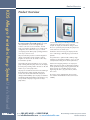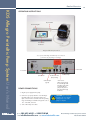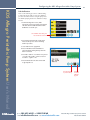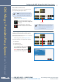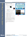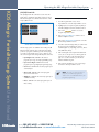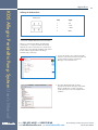
1
KDS Allegro Peristaltic
Pump System
USER’S MANUAL
KDS ALLEGRO PERISTALTIC PUMP SYSTEM
w w w. k d s c i e n t i f i c . c o m
Publication 5613-004-REV-A
Table of Contents
2
KDS Allegro Peristaltic Pump System User’s Manual
Table of Contents
SUBJECT
PAGE NO.
General Information..................................................................................................6
Safety Information ............................................................................................................................6
Warranty and Repair Information ..................................................................................................7
Manual Description ................................................................................................................7
Warranty ..................................................................................................................................7
Repair Facilities and Parts ......................................................................................................7
Serial Numbers ........................................................................................................................7
Calibrations ..............................................................................................................................7
Specifications ....................................................................................................................................8
Product Overview....................................................................................................10
Pump Models ..................................................................................................................................11
Allegro Peristaltic Button Reference ..............................................................................................12
Selecting an Item from a Menu List ..............................................................................................13
Messages ........................................................................................................................................13
Entering Values ..............................................................................................................................13
Operating Instructions....................................................................................................................14
Power Connections ........................................................................................................................14
Tubing Loading ..............................................................................................................................15
Configuring the KDS Allegro Peristaltic Pump System ........................................16
Pump Selection ..............................................................................................................................16
Mode Selection ..............................................................................................................................16
Tubing Selection..............................................................................................................................17
Combining Flow Channels ............................................................................................................18
Flow Rate Selection ........................................................................................................................19
Target Volume/Time Selection ......................................................................................................20
Flow Direction ................................................................................................................................20
Tube Run-in ......................................................................................................................................21
Tube Calibration ............................................................................................................................22
Previewing the Configuration ........................................................................................................24
508.429.6809 fax 508.893.0160
e-mail [email protected] web www.kdscientific.com
phone
KD Scientific Allegro Peristaltic Pump System User’s Manual
Publication 5613-004-REV-A
Table of Contents
3
KDS Allegro Peristaltic Pump System User’s Manual
SUBJECT
PAGE NO.
Configuring the Pump’s General Parameters ..............................................................................25
Setting the Audible Alarms ..................................................................................................25
For Near End of Run Selection ............................................................................................26
For a Custom %......................................................................................................................26
Locking the Touchscreen ......................................................................................................27
Setting the Display Brightness ..............................................................................................28
Setting the Pump Address ....................................................................................................29
Resume Run on Power Loss ..................................................................................................30
Setting and Viewing Pump Information ..............................................................................30
Operating the KDS Allegro Peristaltic Pump System ..........................................31
Running the Pump ..........................................................................................................................32
Custom Program Workflow ..........................................................................................................33
Configuring Custom Programs ......................................................................................................34
Configuring New Custom Program ..............................................................................................34
Setting a Delay ..............................................................................................................................36
Creating a Custom New Program ................................................................................................37
Modifying an Existing/User-Defined Program ............................................................................39
Changing the Order of Steps in a Program ........................................................................39
Deleting a Step from a Program ..........................................................................................39
Defining Program Step Parameters ..............................................................................................39
Pump Operation Profiles................................................................................................................40
Constant Rate Profile ............................................................................................................41
Ramp Profile ..........................................................................................................................42
Stepped Profile ......................................................................................................................43
Pulse Profile ............................................................................................................................45
508.429.6809 fax 508.893.0160
e-mail [email protected] web www.kdscientific.com
phone
KD Scientific Allegro Peristaltic Pump System User’s Manual
Publication 5613-004-REV-A
Table of Contents
4
KDS Allegro Peristaltic Pump System User’s Manual
SUBJECT
PAGE NO.
Delay ......................................................................................................................................47
Repeat Step............................................................................................................................47
Stop ........................................................................................................................................48
I/O Event Triggers ................................................................................................................49
I/O (OUT) Trigger (OUT) ........................................................................................................50
I/O (IN) Event ............................................................................................................................51
I/O (IN) Event Link ....................................................................................................................52
Managing Allegro Peristaltic Pump System Programs ................................................................53
Saving a Copy of a Program ..............................................................................................53
Renaming a Program ............................................................................................................53
Appending a Program ..........................................................................................................54
Deleting a Program ..............................................................................................................54
Program Export and Import ..........................................................................................................55
Transfer a Program between Pumps ....................................................................................55
External Pump Control ..................................................................................................................55
Pump Chain Commands ................................................................................................................56
System Commands ................................................................................................................57
Run Commands......................................................................................................................59
Rate Commands ....................................................................................................................59
Volume Commands ..............................................................................................................60
Time Commands ....................................................................................................................61
Digital I/O Commands ........................................................................................................62
Internal Commands ..............................................................................................................62
Error Codes ....................................................................................................................................63
508.429.6809 fax 508.893.0160
e-mail [email protected] web www.kdscientific.com
phone
KD Scientific Allegro Peristaltic Pump System User’s Manual
Publication 5613-004-REV-A
Table of Contents
5
KDS Allegro Peristaltic Pump System User’s Manual
SUBJECT
PAGE NO.
Appendices ..............................................................................................................65
Appendix A: Allegro Peristaltic Pump System Tubing Table ......................................................65
Appendix B: Tube Break-in Programs ..........................................................................................66
Appendix C: External Connections ..............................................................................................67
User I/O Connector Specifications ....................................................................................67
Utilizing USB Interface..........................................................................................................68
RS-485....................................................................................................................................70
Appendix D: Maintenance............................................................................................................71
Maintenance ....................................................................................................................71
Upgrading Allegro Peristaltic Pump System Software ..................................................72
Troubleshooting ................................................................................................................73
Appendix E: Ordering Information ..............................................................................................74
508.429.6809 fax 508.893.0160
e-mail [email protected] web www.kdscientific.com
phone
KD Scientific Allegro Peristaltic Pump System User’s Manual
Publication 5613-004-REV-A
General Information
6
KDS Allegro Peristaltic Pump System User’s Manual
General Information
SAFETY INFORMATION
Please read the following safety precautions to ensure proper use of your peristaltic pump. If the equipment is
used in a manner not specified, the protection provided by the equipment may be impaired.
To Prevent Hazard or Injury:
USE PROPER POWER SUPPLY
The pump is supplied with an approved power supply and line cord. To maintain the safety integrity of the device,
use only the following power supplies:
Globtek Inc.
Model: GTM – 21097 – 5048 – 18
Output: 30V – 1.67A
Input:
100–240V~50–60 Hz 0.6A
USE PROPER LINE CORD
Use only the specified line cord for this product and make sure line cord is certified for country of use. The
operating voltage range for the KDS Allegro Peristaltic Pump System is 30 VDC. The universal power supply
operating voltage range is 100-240 VAC, 50-60 Hz.
GROUND THE PRODUCT
This product is grounded through the grounding conductor of the power cord. To avoid electric shock, the
grounding conductor must be connected to earth ground. Before making any connections to the input or output
terminals of the product, ensure that the product is properly grounded.
MAKE PROPER CONNECTIONS
Make sure all connections are made properly and securely. Any signal wire connections to the unit must be no longer than 3
meters.
OBSERVE ALL TERMINAL RATINGS
Review the operating manual to learn the ratings on all connections.
AVOID EXPOSED CIRCUITRY
Do not touch any electronic circuitry inside of the product.
AVOID PINCH HAZARD
A pinch hazard may exist between the pusher block and end blocks. Avoid placing fingers between these points
while the pump is running.
DO NOT OPERATE WITH SUSPECTED FAILURES
If damage is suspected on or to the product do not operate the product. Contact qualified service personnel to perform
inspection.
ORIENT THE EQUIPMENT PROPERLY
Do not orient the equipment so that it is difficult to operate the disconnection device.
PLACE PRODUCT IN PROPER ENVIRONMENT
Review the operating manual for guidelines for proper operating environments.
OBSERVE ALL WARNING LABELS ON PRODUCT
Read all labels on product to ensure proper usage.
!
CAUTION
Refer to Manual
Protective Ground
Terminal
508.429.6809 fax 508.893.0160
e-mail [email protected] web www.kdscientific.com
phone
KD Scientific Allegro Peristaltic Pump System User’s Manual
Publication 5613-004-REV-A
General Information
7
KDS Allegro Peristaltic Pump System User’s Manual
WARRANTY AND REPAIR INFORMATION
!
CAUTION: REFER TO SAFETY INFORMATION AND SETTING UP THE KDS Allegro
Peristaltic Pump System BEFORE PLUGGING IN THE PUMP.
Manual Description
This manual is designed to provide all operational and program information required to operate and maintain the
KDS Allegro Peristaltic Pump System. The functions and features are described in the Technical Specifications section.
Warranty
KD Scientific warranties this instrument for a period of one year from date of purchase. At its option, KD Scientific will
repair or replace the unit if it is found to be defective as to workmanship or materials. This warranty does not extend to
damage resulting from misuse, neglect or abuse, normal wear and tear, or accident. This warranty extends only to the
original consumer purchaser.
IN NO EVENT SHALL KD SCIENTIFIC BE LIABLE FOR INCIDENTAL OR CONSEQUENTIAL DAMAGES. Some
states do not allow the exclusion or limitation of incidental or consequential damages so the above limitation or
exclusion may not apply to you. THERE ARE NO IMPLIED WARRANTIES OF MERCHANTABILITY, OR FITNESS
FOR A PARTICULAR USE, OR OF ANY OTHER NATURE. Some states do not allow this limitation on an implied
warranty, so the above limitation may not apply to you.
If a defect arises within the warranty period, promptly contact KD Scientific, 84 October Hill Road, Holliston,
Massachusetts 01746 at 1–508-429-6809. Email address is [email protected]. Goods will not be accepted for
return unless an RMA (returned materials authorization) number has been issued by our customer service department.
The customer is responsible for shipping charges for non-warranty repairs. Please allow a reasonable period of time
for completion of repairs or replacement. If the unit is replaced, the replacement unit is covered only for the remainder
of the original warranty period dating from the purchase of the original device.
This warranty gives you specific rights, and you may also have other rights which vary from state to state.
Repair Facilities and Parts
KD Scientific stocks replacement and repair parts. When ordering, please describe parts as completely as possible,
preferably using a part number obtained from our Customer Service department. If practical, enclose a sample part
or sketch. We offer a complete reconditioning service.
Serial Numbers
All inquiries concerning our product should refer to the serial number of the unit, located on the rear panel.
Calibrations
All electrical apparatus are calibrated at rated voltage and frequency. KD Scientific recommends an annual
calibration of the pump.
!
CAUTION: For research use only. Not for clinical use on patients.
508.429.6809 fax 508.893.0160
e-mail [email protected] web www.kdscientific.com
phone
KD Scientific Allegro Peristaltic Pump System User’s Manual
Publication 5613-004-REV-A
General Information
8
KDS Allegro Peristaltic Pump System User’s Manual
Specifications
Accuracy
± 0.5%
Tubing (Min./Max.)
0.8-8.0 mm (Allegro I, III); 0.8-4.8 mm (Allegro II)
Tubing Durometer Range (Min./Max.)
55A-62A
Flow Rate
(per channel, tubing dependant)*
Display
Non-Volatile Memory
4.3" WQVGA TFT Color Display with
Touch Screen
Stores all settings
Connectors:
RS-485
IEEE-1394, 6 pos
USB
Type B
I/O & TTL
15 pin D-Sub Connector
Footswitch
mini phone jack
Pressure (Max)
30 psi
Drive Motor
1.8° Stepper Motor
Motor Drive Control
Microprocessor with 1/16 microstepping
Step Rate:
Minimum
27.5 sec/µstep
Maximum
26 µsec/µstep
Maximum RPM:
Allegro I
375
Allegro II/III
312
Input Power
30 VDC
Input Power Connection
2.5mm ID x 5.5mm OD male plug
Power Supply
Dimensions (Control Box) (W x D x H)
100-240 VAC, 50-60 Hz, 8 Watts Universal
Power Supply, Use Only a KD Scientific
Approved Power Supply and Line Cord
22.9 x 19.7 x 7.6 cm (9.0 x 7.75 x 3.0 in)
Dimensions (Pump Head) (W x D x H)
11.5 x 24.1 x 11.8 cm (4.5 x 9.5 x 4.63 in)
Weight
2.66 kg (5.9 lbs)
*Please see tubing table (Appendix A).
508.429.6809 fax 508.893.0160
e-mail [email protected] web www.kdscientific.com
phone
KD Scientific Allegro Peristaltic Pump System User’s Manual
Publication 5613-004-REV-A
General Information
9
KDS Allegro Peristaltic Pump System User’s Manual
Specifications (continued)
Atmospheric Specifications:
Operating Temperature
4°C to 40°C (40°F to 104°F)
Storage Temperature
-10°C to 70°C (14°F to 158°F)
Operating Humidity
See Chart Below
Storage Humidity
20% to 80% RH, non condensing
Method of Operation
Continuous
Classification
Class I
Pollution Degree
1
Installation Category
II
Supplier Name
KDS
Supplier Address
84 October Hill Rd., Holliston, MA 01746
Supplier Phone Number
(508) 429-6809
Regulatory Certifications
CE, ETL (UL & CSA), CB Scheme, EU RoHS, WEEE
Safety Declarations
ANSI/UL 61010-1:2004 Ed. 2 Rev. 2005; CAN/CSA
C22.2 No. 61010-1:2004 Ed. 2; IEC 61010-1:2001
Ed. 2 Corrigendum 1:2002, Corrigendum 2:2003;
CENELEC EN 61010-1:2001; CB Scheme
EMC Declaration
IEC 61326-1 Ed. 1
Controller Box
508.429.6809 fax 508.893.0160
e-mail [email protected] web www.kdscientific.com
phone
KD Scientific Allegro Peristaltic Pump System User’s Manual
Publication 5613-004-REV-A
Product Overview
10
KDS Allegro Peristaltic Pump System User’s Manual
Product Overview
The KD Scientific Allegro Peristaltic Pump System is
the next generation of peristaltic pumps. The system
offers unparalleled ease of use through the high
resolution color touch screen user interface. The full
touch screen interface enables the user to quickly create
configurations and recall them for easy use. The TFT
color display presents all the pump operating parameters
on an easy to view run screen.
The password feature prevents accidental configuration
changes ensuring the program’s integrity is retained.
Programs can also be set to be started on a time delay
for unattended operation.
An led light on the front panel makes it easy to see if the
pump is running. Once the pump starts to run, the display
shows the pump is running and the LED turns on. This will
make it easy to see the pump’s status.
The pumps are versatile and can be interconnected through
the RS-485 interface. Allegro Peristaltic Pump System
models can be mixed and matched in the daisy chain
offering maximum flexibility. Up to 99 pumps can be linked
together through the RS-485 interface. This interface is easy
to use provided each pump is assigned its own unique
pump address.
For limited laboratory space the Allegro Peristaltic Pump
controller can be placed on its side to reduce the
footprint. The display also tilts with the change to allow
the user to operate the pump vertically. The pump heads
can be stacked to save bench space.
Notifications and error messages are displayed for the
user to acknowledge, eliminating any guesswork about
problems.
Flow performance is optimized with a small step angle
stepping motor. The tubing mechanism is easy to use and
securely holds the tubing for smooth flow performance.
Advanced microstepping techniques are employed to
further reduce the step angle to eliminate flow pulsation.
A wide dynamic flow range can be programmed into the
pump. Flow rates are selectable with user selected
engineering units from L, ml, µl, nl and hours, minutes
and seconds.
The superior design of the full metal chassis provides
noise isolation and anti-vibration features for increased
reliability.
508.429.6809 fax 508.893.0160
e-mail [email protected] web www.kdscientific.com
phone
KD Scientific Allegro Peristaltic Pump System User’s Manual
Publication 5617-006 Rev E
Product Overview
11
KDS Allegro Peristaltic Pump System User’s Manual
Easy external connections to a computer or other control
devices are made through USB interface. Simple ASCII
commands make communication with the pump easy. For
direct control of the pump, the user can use the I/O
interface (15pin Dsub). A trigger output and a trigger
input in for external events such as a process parameter is
met. The footswitch input will allow the control of the
pump through an external device. The unit also has an
output for run indication allowing connection to a remote
light.
The forward/reverse dispensing programmable model
Allegro offers maximum flexibility and capability for
configuring and running different programs. Multiple
programs of 50 steps each can be configured and stored
in the unit, and recalled quickly with the touch of a
button. The programs are identified with a 15 character
alphanumeric name for easy identification and can be
stored on the computer and downloaded at future dates.
A relative clock is available to start and stop programs
based on time. Extensive programming options allow the
user to duplicate configurations, append one
configuration to another, rename programs, delete
programs, export programs to a PC or export a program
to another pump. This feature can ensure consistency and
accuracy of multiple pumps.
Pump Models
The Allegro Peristaltic Pump System is available in 3
different configurations.
Allegro I Peristaltic Pump System – Single channel
pump head and controller.
Allegro II Peristaltic Pump System – Dual channel
pump head and controller
Allegro III Peristaltic Pump System – Two stacked
single channel pump heads and controller.
Preprogrammed profiles include Constant Rate and
Ramp. These standard profiles make configuration easy
to set up. If more complexity is needed the user can select
from advanced programming options including:
• Time delays
• Repeating steps
• Stopping the pump
• Triggering the pumps TTL output
• Accepting an event input in such as a user
touch
• Events can trigger the pump to dispense in
forward or reverse
The pump Information/setup screen shows the pump’s
software version. The pump’s alarm configurability
includes alarms for near end of run (user selectable),
completion of run, power up, keypad clicks and stall
detection.
508.429.6809 fax 508.893.0160
e-mail [email protected] web www.kdscientific.com
phone
KD Scientific Allegro Peristaltic Pump System User’s Manual
Publication 5613-004-REV-A
Product Overview
12
KDS Allegro Peristaltic Pump System User’s Manual
ALLEGRO PERISTALTIC PUMP SYSTEM TOUCHSCREEN BUTTON REFERENCE
The following buttons are part of the KDS Allegro Peristaltic Pump System software:
Settings: Access the settings menu used to
adjust the following parameters: Audible Alarms,
Pusher Block Force, Display Brightness, etc.
Fast Forward: Rotates in the forward (infuse)
direction (press & hold).
Minimum Value Allowed: Used to
select minimum value allowed.
Maximum Value Allowed: Used to select
maximum value allowed.
Configure: Used to set up the program.
Fast Reverse: Rotates in the reverse (withdraw)
direction (press & hold).
Back: Used to call the Mode and Programs menu.
Rate Increase: Increases dispensing rate.
Page Down: Used to page down in a display list.
Rate Decrease: Decreases dispensing rate.
Page Up: Used to page up in a display list.
Direction (RD): Reverse direction.
Line Up: Used to scroll up in a display list.
Direction (FD): Forward direction.
Line Down: Used to scroll down in a display list.
Accept: Used to accept the parameters/settings on
a screen and return to previous screen in the menu.
Cancel: Used to cancel any changes/entries on a
screen and return to the previous screen in the menu.
Insert Step: Used to insert a new Step in a Program
while editing/creating the Program. The new Step is
inserted after the Step that is currently selected.
Set Delay Parameters: Used to set the time
values for delayed operation. This permits the
pump to start automatically at a preset time
interval.
Delete Step: Used to delete the selected Step in a
Program while editing/creating the Program. To
confirm deletion, you must select the Delete Step
button a second time.
Set Delay Parameters: Indicates the Delay
Timer has been set. The pump will start
automatically.
Move Step Up: Moves the currently selected Step
in a Program up one position in the Program Order
(e.g. Step 3 becomes Step 2).
Run Preview: Access the Run Preview screen that
shows a summary operating parameters.
Move Step Down: Moves the currently selected
Step in a Program down one position in the
Program Order (e.g. Step 2 becomes Step 3).
Run/Resume: Used to Run or Resume a Program.
Copy Step: Creates a duplicate (copy) of the
currently selected Step in a Program and inserts it as
the last Step in the Program being created/edited.
Re-Run: Clears counters/timers (except the Total
Infused Volume counter) and runs the selected
program from the beginning.
Password Protection Off: Indicates that the pump
is currently unlocked. Pressing the button twice locks
the Touchpad.
Stop: Used to stop running a Program.
Password Protection On: Indicates that the pump
is currently locked. Press the button and enter
password to unlock the Touchpad.
Reset: Resets all counters/timers.
File Options: Access the File Options menu that is
used to manage the list of Programs and to export
Program information to an externally linked pump or
to a connected computer.
508.429.6809 fax 508.893.0160
e-mail [email protected] web www.kdscientific.com
phone
KD Scientific Allegro Peristaltic Pump System User’s Manual
Publication 5613-004-REV-A
Product Overview
13
KDS Allegro Peristaltic Pump System User’s Manual
Selecting An Item From a Menu List
Selecting items is easy with the Allegro Peristaltic Pump System.
Touch the item to select/highlight the item,
then touch again to select it or press
Canceling a Selection
Canceling selections is easy.
Press
Messages
There are different types of messages.
Error messages are shown in yellow.
•
•
•
•
Critical
Run--mode
Program
Set-up
Notices, alarms, confirming, and verified
messages are show in green.
• Alarms
• Confirm
• Verified
Entering Values
Entering new values is easy.
Use the keypad to
enter the number
Decimal point
Backspace Key
508.429.6809 fax 508.893.0160
e-mail [email protected] web www.kdscientific.com
phone
Cancel and go back Accept the value and
to the previous screen go back up to the
previous screen
KD Scientific Allegro Peristaltic Pump System User’s Manual
Publication 5613-004-REV-A
Product Overview
14
KDS Allegro Peristaltic Pump System User’s Manual
OPERATING INSTRUCTIONS
Run / Fault LED
Protective Antiglare
User Interface
Touchscreen
Allegro Peristaltic Pump shown above
Close up view of the Allegro Peristaltic Pump rear connections
(connections vary depending on model type)
Main Switch
Foot Switch
RS-485 Connection
I/O Connector
DC Power Input
(Pump to Pump)
USB Serial Input
*Power Source -
(Type B)
When powering a pump
in a chain through an RS485 cable, toggle switch
to RS-485. Only one
pump can be powered
from the master through
the RS-485.
POWER CONNECTIONS
1. Plug the power supply into the pump.
2. Connect to a properly rated line cord. The Allegro
Peristaltic Pump power supply has a DC power
input connector on the rear of the unit. The operating
range for the Allegro Peristaltic Pump System series is
100 – 240 VAC, 50-60 Hz.
!
CAUTION: Do not connect to
firewire ports on a computer.
Damage may occur to the
pump or computer.
3. Turn on the main power switch.
508.429.6809 fax 508.893.0160
e-mail [email protected] web www.kdscientific.com
phone
KD Scientific Allegro Peristaltic Pump System User’s Manual
Publication 5613-004-REV-A
Product Overview
15
KDS Allegro Peristaltic Pump System User’s Manual
TUBE LOADING
1. Turn off the Allegro Peristaltic Pump controller.
!
CAUTION: Stop the drive when
changing the tubing or its position in the
rotor mechanism (the rotor is partially
exposed when the LOADING LEVER is
in the open position).
Figure 1: Open and Load Pump Head
2. Rotate the lever to the left to open the pump head.
3. Load the correct size tubing between the retainers.
Please use Masterflex L/S® tubing only. Center the
tubing between the retainers as shown in Figure 1.
4. Rotate the lever to the right to close as shown in
Figure 2.
Figure 2: Close Pump Head
Note: The Allegro I single channel head is shown in Figure
1 & 2. The above instructions also apply to the dual
channel head used on the Allegro II model and the two
stacked single channel heads used in the Allegro III model.
508.429.6809 fax 508.893.0160
e-mail [email protected] web www.kdscientific.com
phone
KD Scientific Allegro Peristaltic Pump System User’s Manual
Publication 5613-004-REV-A
Configuring the KDS Allegro Peristaltic Pump System
16
KDS Allegro Peristaltic Pump System User’s Manual
Configuring the KDS Allegro Peristaltic Pump System
The KDS Allegro Peristaltic Pump System program is easy
to set up.
Select Mode Select Tubing Manufacturer Size
The Allegro Peristaltic Pump System is easily
configured. When the unit is powered up, the
Configuration Screen will be displayed.
General
Pump
Parameter
Set-Up
Preview
Program
Jumps to
Run
Screen
Select Flow Rates
Select Target Volume
Fast Reverse
Fast Forward
Press and hold to activate
Pump Selection
The Allegro Peristaltic pump must be configured to run
with the installed head configuration.
1) Select the Setup button to enter the Set-up
menu.
2) Choose the proper button for your pump type.
Select I for the Allegro I, II for the Allegro II or III
for the Allegro III.
Pump Type Selection
Mode Selection
Select MODE in the Configuration Display menu and the
Mode Selection screen will be displayed.
The available modes are as follows:
Dispense Mode: Dispense mode is the main operating
mode for the Allegro Peristaltic Pump System.
New Program: Program Mode allows the user to create
automatic dispense programs and save them for later
use.
Note: All created programs will be listed in the mode
directory.
508.429.6809 fax 508.893.0160
e-mail [email protected] web www.kdscientific.com
phone
KD Scientific Allegro Peristaltic Pump System User’s Manual
Publication 5613-004-REV-A
Configuring the KDS Allegro Peristaltic Pump System
17
KDS Allegro Peristaltic Pump System User’s Manual
Tubing Selection
1. In the Configuration Display select the
Tubing button. The Tubing Selection Screen
will be displayed.
2. The Tubing Selection screen contains a Custom
Tubing and Standard Tubing selection. Press the
Standard Tubing button to select a predefined
tubing size. Use the Line Up/Down and
Page Up/Down buttons to scroll through the
selections. Select the desired tubing and
press Enter.
Press
Note: When changing tubing sizes,
please recalibrate the tubing before
using. Please see the Tube Calibration
section of this manual.
Press
3. For a Custom Tubing size, use this selection.
Press to enter a
custom tubing
Custom Tubing Definition Display
Press to enter the inside
diameter of the tubing
508.429.6809 fax 508.893.0160
e-mail [email protected] web www.kdscientific.com
phone
KD Scientific Allegro Peristaltic Pump System User’s Manual
Publication 5613-004-REV-A
Configuring the KDS Allegro Peristaltic Pump System
18
KDS Allegro Peristaltic Pump System User’s Manual
Combining Flow Channels
For Allegro II & Allegro III systems, the flow channels can
be combined into a single output.
1. Toggle the Combined Flow Icon
will change to:
2. When flow channels are combined, a note is
added to the configuration and run screens.
508.429.6809 fax 508.893.0160
e-mail [email protected] web www.kdscientific.com
phone
KD Scientific Allego Peristaltic Pump System User’s Manual
Publication 5613-004-REV-A
Configuring the KDS Allegro Peristaltic Pump System
19
KDS Allegro Peristaltic Pump System User’s Manual
Flow Rate Selection
1. In the Configuration Display enter the flow
rate by pressing Rate on the Configuration
screen. In this example we want to enter
150 ml/min.
Press
2. To change the units, press the units.
Press to change the units
Enter the flow rate
Press to select the
maximum flow rate for the
tubing size selected
Press to select the
minimum flow rate for the
tubing size selected
3. In the Units Selection Display select the volume
and the time base.
508.429.6809 fax 508.893.0160
e-mail [email protected] web www.kdscientific.com
phone
KD Scientific Allegro Peristaltic Pump System User’s Manual
Publication 5613-004-REV-A
Configuring the KDS Allegro Peristaltic Pump System
20
KDS Allegro Peristaltic Pump System User’s Manual
Target Volume/Time Selection
1. In the Configuration Display enter the target
volume or time. In this example we want a
volume of 5 L.
✐
NOTE: For time enter h:m:s. or press
again to select secs. Time is accurate to
+/- 0.01secs. Remember to enter the :
Press Here
Press to change the units
2. To change the units, press the units.
Press to select target volume
Press to select target time
3. In the Units Selection Display select the
volume units.
Flow Direction
1. The flow direction is set on the Run screen. Press
the Run Preview button on the Configuration
screen to enter the Run screen.
2. On the Run screen select the Reverse Direction
button to run the flow in the reverse (counter
clockwise) direction or select the right Forward
Direction button to run the flow in the forward
(clockwise) direction.
Reverse
Direction
button
508.429.6809 fax 508.893.0160
e-mail [email protected] web www.kdscientific.com
phone
Forward
Direction
button
KD Scientific Allegro Peristaltic Pump System User’s Manual
Publication 5613-004-REV-A
Configuring the KDS Allegro Peristaltic Pump System
21
KDS Allegro Peristaltic Pump System User’s Manual
Tube Run-In
New tubing or tubing that has been idle for extended
periods should be run-in prior to use. The pump comes
standard with programs to complete this task. Any tube
size that meets the diameter specifications for the
appropriate pump head can be used.
1. From the Mode Selection screen, select the
proper program for the head configuration of
the pump.
Please select program I_BREAK_IN for the
Allegro I, II_BREAK_IN for the Allegro II or
III_BREAK_IN for the Allegro III.
Tubing Break-In Selections
2. Once the proper tube break-in program is
selected, the Program Configuration screen
will open.
3. Select the Run button to start the break-in
program. The program run time is 15 minutes.
Select Run to start the
break-in program
✐
NOTE: Large diameter and/or high
durometer tubing require lubrication of
tubing. See Appendix E for ordering
information.
508.429.6809 fax 508.893.0160
e-mail [email protected] web www.kdscientific.com
phone
KD Scientific Allego Peristaltic Pump System User’s Manual
Publication 5613-004-REV-A
Configuring the KDS Allegro Peristaltic Pump System
22
KDS Allegro Peristaltic Pump System User’s Manual
Tube Calibration
Please use the following procedure to calibrate tubing.
To achieve the best possible accuracy, the calibration
procedure should be run before using the pump. Please
note that the pumping direction for calibration is always
forward.
1. From the Configuration screen, make
appropriate selections for tubing size and flow
rate and select the Calibrate button and the
Calibration screen will open.
Select Calibrate when tubing and
flow rate have been entered
2. Insert appropriate tubing into Pump Head.
Please see the previous section for tubing
break-in procedure.
3. Insert tube inlet into supply fluid.
4. Press and hold the fast forward button to
prime the tubing. Priming will stop when the
button is released.
5. Insert tube outlet into a container to be placed
on a scale. The weight to volume conversion
for water is 1 gram = 1 ml.
6. Press the Run button. The drive will run until
stopped by the user.
Select Fast Forward
to prime the tubing
508.429.6809 fax 508.893.0160
e-mail [email protected] web www.kdscientific.com
phone
Select Run
to start the
calibration
program
KD Scientific Allego Peristaltic Pump System User’s Manual
Publication 5613-004-REV-A
Configuring the KDS Allegro Peristaltic Pump System
23
KDS Allegro Peristaltic Pump System User’s Manual
7. Upon completion of the calibration run period,
the ‘Enter Volume Delivered’ button will be
activated. Please note the Volume reading listed
under the Tubing and Rate information on the
Calibration screen.
8. Select the Enter Volume Delivered button and
enter the Volume as measured on your scale
into the keypad and press Enter.
9. Press Enter on the Calibration screen to save
the setting or select the Run button to start the
procedure over again, or press the Reset
Calibration button to reset to the Factory
default value.
508.429.6809 fax 508.893.0160
e-mail [email protected] web www.kdscientific.com
phone
KD Scientific Allego Peristaltic Pump System User’s Manual
Publication 5613-004-REV-A
Configuring the KDS Allegro Peristaltic Pump System
24
KDS Allegro Peristaltic Pump System User’s Manual
Previewing the Configuration
It is simple to view the Pump Configuration on the
RUN display.
Press
to view Pump Configuration
After you have verified the configuration.
Press
to run the displayed configuration.
Press to preview
configuration
Configuring the Pump’s
General Parameters
The pump has basic parameters that should be
configured during initial start-up. Once these parameters
are entered they probably won’t be changed.
To enter the set-up screen press
508.429.6809 fax 508.893.0160
e-mail [email protected] web www.kdscientific.com
phone
KD Scientific Allegro Peristaltic Pump System User’s Manual
Publication 5613-004-REV-A
Configuring the KDS Allegro Peristaltic Pump System
25
KDS Allegro Peristaltic Pump System User’s Manual
Setting the Audible Alarms
In the Set-up screen , press Audible Alarms.
Select the alarms, a check mark will
indicate the alarms selected.
Press
If these alarms are selected the pump
will provide an audible alarm.
Accept the changes made by pressing
and go back to the Set-up screen.
Cancel the changes made by pressing
and go back to the Set-up screen.
End of Run –
Alarm when
the program
is finished
Power Fail –
Alarm when
pump is powercycled while
running
Keypad Clicks – When
the keypad is touched,
the unit will provide
audible feedback
Stall – Motor stalls
Near End of Run – When the volume
dispensed is reached for the specified %
Mute All – No audible sounds
508.429.6809 fax 508.893.0160
e-mail [email protected] web www.kdscientific.com
phone
KD Scientific Allegro Peristaltic Pump System User’s Manual
Publication 5613-004-REV-A
Configuring the KDS Allegro Peristaltic Pump System
26
KDS Allegro Peristaltic Pump System User’s Manual
For Near End of Run Selection
Select the % volume dispensed. For example, if
you select 80%, the pump will sound an alarm
(3 short beeps) when the 80% of the volume is
dispensed.
Accept the changes made by pressing
and go back to the Set-up screen.
Cancel the changes made by pressing
and go back to the Set-up screen.
Press to select %
volume dispensed
For a Custom %
Use this selection if the % is not listed.
Press Other Value to enter a custom %
Accept the changes made by pressing
and go back to the Set-up screen.
Cancel the changes made by pressing
and go back to the Set-up screen.
Press to enter
a custom %
Enter the percentage.
Accept the changes made by pressing
and go back to the Set-up screen.
Cancel the changes made by pressing
and go back to the Set-up screen.
508.429.6809 fax 508.893.0160
e-mail [email protected] web www.kdscientific.com
phone
KD Scientific Allegro Peristaltic Pump System User’s Manual
Publication 5613-004-REV-A
Configuring the KDS Allegro Peristaltic Pump System
27
KDS Allegro Peristaltic Pump System User’s Manual
Locking the Touchscreen (Password
Protection)
A touchscreen lock function can be enabled to
prevent accidental operation or interruption of
operation. Unlocking the touchscreen requires a
password, defined by the user.
Set password
Setting the Password
To set the Password go to the Settings screen.
Press the Set Password button.
Enter your desired password, up to 6 digits, and
press the “ACCEPT” button.
Turning the Touchscreen Lock on
Press the Lock button twice to lock the
touchscreen.
Password
Turning the Touchscreen Lock off
Press the “LOCK” button to bring up the Enter the
Pump Password screen.
Enter your password and press the “ACCEPT”
button.
✐
NOTE: If you forget your password
contact KD Scientific Technical Support
at 508-429-6809.
508.429.6809 fax 508.893.0160
e-mail [email protected] web www.kdscientific.com
phone
KD Scientific Allegro Peristaltic Pump System User’s Manual
Publication 5613-004-REV-A
Configuring the KDS Allegro Peristaltic Pump System
28
KDS Allegro Peristaltic Pump System User’s Manual
Setting Display Brightness
The backlight can be adjusted.
In the Set-up screen, select Display Brightness
Press to select % Display Brightness
Select the % Display Brightness. For example, if
you select 80%, the brightness of the display will
be 80% of the maximum.
Accept the changes made by pressing
and go back to the Set-up screen.
Press Here
Cancel the changes made by pressing
and go back to the Set-up screen.
For a Custom Value
Use this selection if the % is not listed.
Press Other Value to enter a custom %
Enter the percentage.
Accept the changes made by pressing
and go back to the Set-up screen.
Cancel the changes made by pressing
and go back to the Set-up screen.
Press here for custom
display brightness level
508.429.6809 fax 508.893.0160
e-mail [email protected] web www.kdscientific.com
phone
KD Scientific Allegro Peristaltic Pump System User’s Manual
Publication 5613-004-REV-A
Configuring the KDS Allegro Peristaltic Pump System
29
KDS Allegro Peristaltic Pump System User’s Manual
Setting the Pump Address
Up to 100 pumps can be linked together. Each pump
can be given a unique address.
In the Set-up Screen press Pump Address.
Valid entries are 00 to 99.
Enter the pump address.
Accept the changes made by pressing
and go back to the Set-up screen.
Cancel the changes made by pressing
and go back to the Set-up screen.
508.429.6809 fax 508.893.0160
e-mail [email protected] web www.kdscientific.com
phone
Press Here
KD Scientific Allegro Peristaltic Pump System User’s Manual
Publication 5613-004-REV-A
Configuring the KDS Allegro Peristaltic Pump System
30
KDS Allegro Peristaltic Pump System User’s Manual
Resume Run on Power Loss
If Resume Run on Power Loss is selected the pump will
power up running when power resumes.
✐
NOTE: This feature will only execute if the
pump is running at the time when power is
lost, and was running with no target set.
In the Set-up screen,
select Resume Run After Power Loss
Accept the changes made and go back
to the previous screen before Set-up mode
was selected.
Cancel and go back to the previous
screen before Set-up mode was selected.
Press Here
✐
NOTE: Elapsed Timers and Total Infused
Volume will be reset when power resumes.
Counters and timers information prior to
loss of power are lost
Setting and Viewing Pump Information
The information on the pump’s parameters are displayed
in the Pump Information Screen.
In the Set-up screen, select Pump Information
The current information on the pump will be displayed.
• The Model type
• The Software Version
• The Current Pump Address
Accept the changes made by pressing
and go back to the Set-up screen.
Press Here
Cancel the changes made by pressing
and go back to the Set-up screen.
508.429.6809 fax 508.893.0160
e-mail [email protected] web www.kdscientific.com
phone
KD Scientific Allegro Peristaltic Pump System User’s Manual
Publication 5613-004-REV-A
Operating the KDS Allegro Peristaltic Pump System
31
KDS Allegro Peristaltic Pump System User’s Manual
Operating the Pump
The Allegro Peristaltic Pump System is easy to operate
because all the pump parameters are shown on the RUN
Screen. Depending on the mode of the pump, different
parameters will be shown on the display.
The Allegro Peristaltic Pump System Run Screen is
shown below.
Press to go to Set-up screen Press to go to Lock/Unlock on the touch screen
Current flow rate
Program settings
Indicates current
flow direction
Total elapsed time
Total remaining time
Total volume dispensed
Press to reset Time and Volumes
Status of current
pump operation
Flow rate increase/decrease
Fast forward
Fast reverse
Press to
Start/Stop
the pump
Press to go to
Configuration
Screen
508.429.6809 fax 508.893.0160
e-mail [email protected] web www.kdscientific.com
phone
KD Scientific Allegro Peristaltic Pump System User’s Manual
Publication 5613-004-REV-A
Operating the KDS Allegro Peristaltic Pump System
32
KDS Allegro Peristaltic Pump System User’s Manual
Running the Pump
Simply press the
button to start the pump.
When the pump is running the
is shown.
Press the
button
button to pause the program.
Press Here
✐
NOTE: The fast forward and fast reverse
keys are not active (grayed out) when the
pump is running.
508.429.6809 fax 508.893.0160
e-mail [email protected] web www.kdscientific.com
phone
KD Scientific Allegro Peristaltic Pump System User’s Manual
Publication 5613-004-REV-A
Operating the KDS Allegro Peristaltic Pump System
33
KDS Allegro Peristaltic Pump System User’s Manual
Custom Program Workflow
The following flow diagram describes the use of
a Custom Program:
Select Program
Select Tubing & Size
OR
Create New Tubing Size
Review Program Steps
(Pump Operation Profiles)
Enter Pump Operation Profile
Parameters
Validate Commands and
I/O Operations
The software provides the user with a variety of prompts
and warnings to help guide the setup of programs. For
example, if a pump Program incorporates steps that
exceed the capacity of the defined tubing, the system will
prompt you that parameters are out-of-range. The system
also prompts users if required values are not entered.
✐
NOTE: The pump will check the validity of
parameters entered for each Step in the
Program, but will not review the Program in
its entirety to verify that it is logical and can
be fully executed
508.429.6809 fax 508.893.0160
e-mail [email protected] web www.kdscientific.com
phone
KD Scientific Allegro Peristaltic Pump System User’s Manual
Publication 5613-004-REV-A
Operating the KDS Allegro Peristaltic Pump System
34
KDS Allegro Peristaltic Pump System User’s Manual
Configuring Custom Programs
The Allegro Peristaltic Pump System offers the flexibility
of configuring custom programs including multistep
programs. The programs and steps can also be triggered
to start and stop with events and external I/O, and user
defined inputs.
Configuring a New Custom Program
To display the Mode Selection
screen press Mode.
Select Mode
The Mode Selection screen will be displayed
Select New Program
Press
View programs up a page
Custom
Programs
View the programs down a page
Views up the program
Views down the program
508.429.6809 fax 508.893.0160
e-mail [email protected] web www.kdscientific.com
phone
KD Scientific Allegro Peristaltic Pump System User’s Manual
Publication 5617-006 Rev E
Operating the KDS Allegro Peristaltic Pump System
35
KDS Allegro Peristaltic Pump System User’s Manual
Configuring Custom Programs
The first thing to do on a custom program is to name the
program.
Enter any 15 character alphanumeric name
Accept the new name
Go back to the Program Selection screen
Select the Tubing Size
(see page 17)
To define the steps for the custom program
press Step Definition
Below are some predefined steps including:
Constant Rate- a single continuous rate of flow
Ramped Rate - a linearly changing flow rate between
a starting and ending flow rate
Stepped Rate - an evenly changing flow rate between
a starting and ending flow rate
Step Definition
Pulsed Rate - an oscillating flow rate varying between
a starting and target flow rate
In addition to these you can repeat, in a program as well
as send signals to external devices or react to signals
received from external devices. This package of pumping
profiles and commands provides users with an extremely
broad array of applications that can be easily configured
with complex external programming.
Programs can be edited and saved under a new name,
allowing them to be simply edited to fit another
application. Steps can be copied, moved, inserted or
deleted.
508.429.6809 fax 508.893.0160
e-mail [email protected] web www.kdscientific.com
phone
KD Scientific Allegro Peristaltic Pump System User’s Manual
Publication 5613-004-REV-A
Operating the KDS Allegro Peristaltic Pump System
36
KDS Allegro Peristaltic Pump System User’s Manual
Setting A Delay
You can set the KDS Allegro Peristaltic Pump System to
run after a delay. This delayed run function allows you to
set up all the parameters for operation, then have the
pump start unattended after a specified amount of time.
SETTING A DELAY FOR PROGRAM OPERATION:
1. From the program configuration screen, choose the
Set Delay button to enter the Set Delay Screen.
2. Enter the desired Time using the keypad.
3. If the Units of your Time are not correct for your
application, select the Units button to toggle
between sec (seconds) and hh:mm:ss
(hours:minutes:seconds). To use the hh:mm:ss
option, enter your time value in hours, minutes,
and seconds, separating each value with a colon.
You can enter a value up to 99:99:99.
4. When the desired values are entered, choose the
Accept button to save your changes and return to
the Program Configuration screen. When a Time
Delay value is active, the Time Delay Parameters
button is displayed in Red on the screen to alert
the user that a delay has been set.
Set Delay Time screen
5. Press the Run button to activate the Delay.
Quick Start run screen with a Time Delay Set
508.429.6809 fax 508.893.0160
e-mail [email protected] web www.kdscientific.com
phone
KD Scientific Allegro Peristaltic Pump System User’s Manual
Publication 5613-004-REV-A
Operating the KDS Allegro Peristaltic Pump System
37
KDS Allegro Peristaltic Pump System User’s Manual
Creating a Custom New Program
The following flow diagram outlines the basic steps you
will follow to create a new Program:
New User-Defined Program creation workflow
TO CREATE A NEW USER-DEFINED PROGRAM
1. From the Program Configuration or Programs
screen, choose the Program Select button to enter
the Program Selection screen.
2. Select New Program then choose Accept or press
New Program again.
3. On the Program Name screen, type the name of
your Program using the onscreen keyboard.
Choose the Symbols/Numbers button
to
display the list of available numbers and symbols
that can be included in the Program Name. To
switch the keyboard back to letters mode, choose
the Letters button (ABC).
New Program Name Entry screen showing letter keys.
To view numbers/symbols, choose the
use button
in the lower left corner
4. When you have entered the desired name for your
Program, choose the Accept button to go to the
Program Configuration screen. Your new Program
will now be listed in the Program Name button.
5. Choose the Tubing Select button and complete the
description of the tubing by following the
procedure outlined previously in the Tubing
Selection section of this Guide.
508.429.6809 fax 508.893.0160
e-mail [email protected] web www.kdscientific.com
phone
KD Scientific Allegro Peristaltic Pump System User’s Manual
Publication 5613-004-REV-A
Operating the KDS Allegro Peristaltic Pump System
38
KDS Allegro Peristaltic Pump System User’s Manual
TO CREATE A NEW USER-DEFINED PROGRAM (CONTINUED)
6. To begin creating Pump Control Profile Steps,
choose the Step Definition button to enter the Step
Definition screen.
7. To add a Step to your Program, choose the Insert
Step button to access the Select Profile for Step
screen. The available options include Constant
Rate, Ramp, Stepped, Pulse and Advanced
Options.
8. Selecting the Advanced Options button will allow
you to access additional Program Step options.
The Available advanced option steps are Go To,
Delay, Repeat, Link, Stop, I/O (out) Trigger,
I/O (in) Event and I/O (out) Event Link.
9. Choose the Program Step type that you want to
add to the Program. If you choose a pumping
profile (e.g. Constant Rate, Ramp, etc.) you will be
taken to the Step Definition screen for the selected
Program.
10. Complete the parameter entry applicable to the
selected Pump Operation Profile; follow the
detailed instructions supplied in the Pump
Operation Profiles (Existing and User-Defined
Programs) section later in this Guide.
11. When you have completed all parameter entries
on the Step Definition screen or completed the
required entries for Advanced Options, choose the
button to save your changes and return to the
Program Steps Summary screen.
12. Repeat items 7-10 in this procedure to include
additional Steps in the Program.
13. When you are done adding all required Steps to
the Program, choose the Enter button to return to
the Program Main screen.
✐
NOTE: When adding a Step to a
Program, the Step is added after the
currently selected Step (i.e. the Step that is
highlighted in blue)
508.429.6809 fax 508.893.0160
e-mail [email protected] web www.kdscientific.com
phone
KD Scientific Allegro Peristaltic Pump System User’s Manual
Publication 5613-004-REV-A
Operating the KDS Allegro Peristaltic Pump System
39
KDS Allegro Peristaltic Pump System User’s Manual
Modifying an Existing User-Defined Program
Once you have created a Program or have reviewed an
Existing Program, you may have a need to modify the
structure of the Program (i.e. the types of Steps and
Commands included, not just changes in the operating
parameters for a specific Step. The following procedures
will help you to efficiently modify a stored Program.
CHANGING THE ORDER OF STEPS IN A PROGRAM
1. From the Program Configuration screen,
choose the Step Definition button to enter the
Program Steps Summary screen.
2. Highlight (select with a single touch) the Step for
which you want to change the order.
3. Choose the Move Step Up or Move Step Down
button, as required, to move the Step into the
position that you want it executed.
DELETING A STEP FROM A PROGRAM
1. From the Program Configuration screen, choose
the Step Definition button to enter the Program
Steps Summary screen.
2. Highlight (select with a single touch) the Step that
you want to delete.
3. Choose the Delete Step button. The application
will display a warning message in the Message
Area asking you to confirm your deletion request.
Delete Program Step showing confirmation message
on the screen
4. To confirm the deletion, choose the Delete Step
button again. The Step is removed and you are
returned to the Program Steps Summary screen.
Defining Program Step Parameters
This section of the User Guide describes each of the
available functions available for use in KDS Allegro
Peristaltic Pump System Existing and User-Defined
Programs. The information in this section is designed to
help you set the individual parameter values in each of
the Program Step options and to properly use the
Advanced Options commands.
The information that follows is organized into two sections:
• Pump Operation Profiles
• Advanced Options (Commands and I/O)
508.429.6809 fax 508.893.0160
e-mail [email protected] web www.kdscientific.com
phone
KD Scientific Allegro Peristaltic Pump System User’s Manual
Publication 5613-004-REV-A
Operating the KDS Allegro Peristaltic Pump System
40
KDS Allegro Peristaltic Pump System User’s Manual
PUMP OPERATION PROFILES
The KDS Allegro Peristaltic Pump System Existing Programs
and all User-Defined Programs use Pump Operation Profiles
as part of the Programs controlling the pump. These profiles
are combined with a tubing selection and any Commands
or Input/Output triggers to create a complete Program. The
following sections describe each profile along with
instructions for setting up the profile.
CONSTANT RATE
RAMP RATE
Flow
Rate
STEPPED RATE
Flow
Rate
Time | Volume
PULSE FLOW
# Steps
Flow
Rate
Time
# Pulses
Flow
Rate
Time | Volume
# Cycles
Time | Volume
Pump Operation Profiles available on the KDS Allegro Peristaltic Pump System.
508.429.6809 fax 508.893.0160
e-mail [email protected] web www.kdscientific.com
phone
KD Scientific Allegro Peristaltic Pump System User’s Manual
Publication 5613-004-REV-A
Operating the KDS Allegro Peristaltic Pump System
41
KDS Allegro Peristaltic Pump System User’s Manual
Constant Rate Profile
TO SET UP/EDIT A CONSTANT RATE PROFILE:
The Constant Rate profile is used to run the pump at a
defined flow rate and for a specific pumping mode
(infuse or withdraw) up to a target volume or for a
defined time period.
1. From the Step Definition screen for a Constant Rate
profile, choose the Direction button to toggle the
Flow Mode between Infuse and Withdraw operation.
2. Choose the Rate button to enter the Set Rate screen.
Flow
Rate
STOP
Target Time or
Total Volume
Point
Time | Volume
Constant Rate Pump Operation Profile
3. Enter the flow rate value desired using the keypad
or select the Minimum Rate or Maximum Rate button.
4. If the Units of Rate are not correct for your
application, choose the Units button.
5. On the Units Selection screen, select the unit of
measure (L, ml, µl, nl or pl) and the unit of time
(sec, min, hr) as appropriate, then choose ‘ENTR’
to confirm your selections.
6. When all parameters are correctly set on the Set
Rate screen, choose ‘ENTR’ to confirm your
settings and return to Constant Rate Definition screen.
7. Choose the Volume button to enter the Set Volume
or Time screen.
When creating or editing a Constant Rate profile, you
will define three primary operating parameters:
• The Flow Mode defining the direction of flow:
forward or reverse
• The Flow Rate to define the rate of uptake or
dispensing
• The Target Volume or Run Time that determine how
long the pump will operate at the set rate
When creating or editing a Constant Rate profile, you
can set the rate in L, ml, µl or nl units of volume using sec,
min or hr as the units of time. The system automatically
calculates a minimum and maximum flow rate based on
the tubing size selected or custom-defined. The min/max
values are made available as button selection options on
the Rate screen.
8. On the Set Volume or Time screen, select the
Volume or Time button, as desired.
9. Enter the desired value using the keypad, or select
the Maximum Volume button.
10. If the Units of Volume/Time are not correct for your
application, choose the Units button to the right of
the parameter entry box. For the Units of Volume,
this choice takes you to the Units Selection screen.
For the Units of Time option, this choice will toggle
the button between sec (seconds) and h:m:s
(hours:minutes:seconds). To use the h:m:s option,
enter your time value in hours, minutes and
seconds, separating each value with a colon.
11. If you are changing the Units of Volume, on the
Units Selection screen, select the unit of measure
(ml, µl, nl or pl) as appropriate, then choose
‘ENTR’ to confirm your selection.
12. When all parameters are correctly set on the Set
Target Volume or Time screen, choose ‘ENTR’ to
confirm your settings and return to the Constant
Rate Definition screen.
13. Choose ‘ENTR’ again to return to the
Step Definition screen.
Constant Rate Profile Setup Screen
508.429.6809 fax 508.893.0160
e-mail [email protected] web www.kdscientific.com
phone
KD Scientific Allegro Peristaltic Pump System User’s Manual
Publication 5613-004-REV-A
Operating the KDS Allegro Peristaltic Pump System
42
KDS Allegro Peristaltic Pump System User’s Manual
Ramp Profile
2. Choose the Set Start & End Rate button to enter
the Set Start & End Rates screen.
The Ramp Rate profile is used to create a linearly increasing
or decreasing flow rate for a single pumping mode (infuse
or withdraw) over the course of a defined time period.
Target Time
Flow
Rate
STOP
Set Start and End Rates screen
Time
Ramp Rate Pump Operation Profile
When creating or editing a Ramp Rate profile, you will
define three primary operating parameters:
3. Select the Start Rate button (it should be selected
by default as indicated by the active data entry
box to the right of the button). Enter the flow rate
value desired using the keypad or select the
Minimum Rate or Maximum Rate button.
• The Flow Mode defining the direction of flow:
forward or reverse
4. If the Units of Rate are not correct for your
application, choose the Units button.
• The Flow Rate at the beginning and end of
the pumping cycle
5. On the Units Selection screen, select the unit
of measure (L, ml, µl or nl) and the unit of time
(sec, min, hr) as appropriate, then
choose ‘ENTR’ to confirm your selections.
• The Target Time that determines the total length
of time over which the ramp will be calculated
During a Ramp Rate profile, the KDS Allegro Peristaltic
Pump System varies the flow rate linearly between the
starting rate and ending rate over the full time period
entered. A Ramp Rate profile can be applied to an
increasing or decreasing rate application.
When creating or editing a Ramp Rate profile, you can set
the rate in L, ml, µl, nl or pl units of volume using sec or
h:m:s (hours:minutes:seconds) as the units of time. The
system automatically calculates a minimum and maximum
flow rate based on the tubing selected or custom-defined.
The min/max values are made available as button selection
options on the Rate screen.
TO SET UP/EDIT A RAMP RATE PROFILE:
1. From the Step Definition screen for a Ramp Rate
profile, choose the Direction button to toggle the
Flow Mode between Forward and Reverse operation.
6. Repeat Steps 3 to 5 for the End Rate by selecting
the End Rate button and continuing data entry.
7. When all parameters are correctly set on the
Set Rate screen, choose ‘ENTR’ to confirm your
settings and return to Ramp Definition screen.
8. Choose the Time button to enter the Set Time screen.
9. Enter the desired Time value using the keypad.
10. If the Units of Time are not correct for your
application, select the Units button to toggle
between sec (seconds) and h:m:s
(hours:minutes:seconds). To use the h:m:s option,
enter your time value in hours, minutes and
seconds, separating each value with a colon.
11. When all parameters are correctly set on the Set
Target Time screen, choose Accept to confirm your
settings and return to the Ramp Definition screen.
12. Choose Accept again to return to the Step
Definition screen.
✐
NOTE: Ramps < 2 seconds from min to
max rates may cause motor stalls.
Step Definition screen for a Ramp Rate profile
508.429.6809 fax 508.893.0160
e-mail [email protected] web www.kdscientific.com
phone
KD Scientific Allegro Peristaltic Pump System User’s Manual
Publication 5613-004-REV-A
Operating the KDS Allegro Peristaltic Pump System
43
KDS Allegro Peristaltic Pump System User’s Manual
Stepped Profile
The Stepped Rate profile is used to create an increasing
or decreasing flow rate that varies in a series of equal
steps between a starting and ending flow rate.
Flow
Rate
# Steps
Time | Volume
Stepped Rate Pump Operation Profile
When creating or editing a Stepped Rate profile, you will
define four primary operating parameters:
• The Flow Mode defining the direction of flow:
forward or reverse
• The Flow Rate at the beginning and end of the
pumping cycle
• The Target Time that determines the total length of
time over which the stepped profile will be
calculated
• The Number of Steps that will be created in
the profile
During a Stepped Rate profile, the KDS Allegro Peristaltic
Pump calculates a series of equal rate increases that will
vary the flow from the starting value to the ending value.
You enter the Number of Steps you want to use. The
Target Time defines the total length of pumping time, with
the Target Time value divided equally into each stepped
rate. A Stepped Rate profile can be applied to an
increasing or decreasing rate application.
When creating or editing a Stepped Rate profile, you can
set the rate in L, ml, µl or nl units of volume using sec or
h:m:s (hours:minutes:seconds) as the units of time. The
system automatically calculates a minimum and maximum
flow rate based on the syringe selected or customdefined. The min/max values are made available as
button selection options on the Set screen.
508.429.6809 fax 508.893.0160
e-mail [email protected] web www.kdscientific.com
phone
KD Scientific Allego Peristaltic Pump System User’s Manual
Publication 5613-004-REV-A
Operating the KDS Allegro Peristaltic Pump System
44
KDS Allegro Peristaltic Pump System User’s Manual
TO SET UP/EDIT A STEPPED RATE PROFILE:
1. From the Stepped Definition screen for a Stepped
Rate profile, choose the Direction button to toggle
the Flow Mode between Infuse and Withdraw
operation.
9. Select the Total Time button (it should be selected
by default as indicated by the active data entry
box to the right of the button). Enter the desired
value using the keypad.
10. If the Units of Time are not correct for your
application, select the Units button to toggle
between sec (seconds) and h:m:s
(hours:minutes:seconds). To use the h:m:s option,
enter your time value in hours, minutes and
seconds, separating each value with a colon.
11. Select the Number of Steps button and enter the
desired value using the keypad.
Step Definition screen for a Stepped Profile
12. When all parameters are correctly set on the Set
Time and Steps screen, choose Accept to confirm
your settings and return to the Stepped Definition
screen.
2. Choose the Rates button to enter the Set Start
and End Rates screen.
Set Start and End Rate screen
3. Select the Start Rate button (it should be selected
by default as indicated by the active data entry
box to the right of the button). Enter the flow rate
value desired using the keypad or select the
Minimum Rate or Maximum Rate button.
4. If the Units of Rate are not correct for your
application, choose the Units button.
5. On the Units Selection screen, select the unit of
measure (ml, µl, nl or pl) and the unit of time (sec,
min, hr) as appropriate, then choose Accept to
confirm your selections.
6. Repeat Steps 3 to 5 for the End Rate by selecting
the End Rate button and continuing data entry.
7. When all parameters are correctly set on the Set
Start and End Rate screen, choose Accept to
confirm your settings and return to Stepped
Definition screen.
8. Choose the Time and # Steps button to enter
the Set Time & Steps screen.
508.429.6809 fax 508.893.0160
e-mail [email protected] web www.kdscientific.com
phone
KD Scientific Allego Peristaltic Pump System User’s Manual
Publication 5613-004-REV-A
Operating the KDS Allegro Peristaltic Pump System
45
KDS Allegro Peristaltic Pump System User’s Manual
Pulse Profile
The Pulse Rate profile is used to create an oscillating
infusion or withdrawal profile that varies between a
starting flow rate and a second rate that can be either or
higher or lower than the start rate. The flow rate is
constant within each segment of the pulsed flow profile
and the user defines the total number of repetitions
(pulses) for the oscillating pattern. Each segment of the
profile must be set to run for either a specific length of
time or to deliver a set volume.
# Pulses
Volume
Time | Volume
Pulse Rate Pump Operation Profile
When creating or editing a Pulse Rate profile, you will
define four primary operating parameters:
• The Flow Mode defining the direction of flow:
forward or reverse
• The Flow Rate to be used at each level of the
pulsed profile within the pumping cycle
• The length of Time that each segment of the profile
will run or the specific Volume to be
infused/withdrawn during each segment of the
profile
•
The Number of Pulses (repetitions) that will be
executed during the pumping cycle
During a Pulse Rate profile, the KDS Allegro Peristaltic
Pump calculates a series of equal length pumping stages
at two user-defined flow rates: a starting rate and a
“pulse” rate. You enter the Number of Pulses (repetitions)
that you want to use, along with how you want the system
to calculate the length of each stage — by time or by
volume pumped. A Pulse Rate profile can be applied to
pulses that are higher in rate or lower in rate than the
starting flow rate.
When creating or editing a Pulse Rate profile, you can set
the rate in L, ml, µl or nl units of volume using sec, min or
hr as the units of time. The system automatically
calculates a minimum and maximum flow rate based on
the syringe selected or custom-defined. The min/max
values are made available as button selection options on
the Set Pulse Rates screens.
508.429.6809 fax 508.893.0160
e-mail [email protected] web www.kdscientific.com
phone
KD Scientific Allego Peristaltic Pump System User’s Manual
Publication 5613-004-REV-A
Operating the KDS Allegro Peristaltic Pump System
46
KDS Allegro Peristaltic Pump System User’s Manual
TO SET UP/EDIT A PULSE RATE PROFILE:
1. From the Pulse Definition screen for a Pulse Rate
profile, choose the Direction button to toggle the
Flow Mode between Infuse and Withdraw
operation.
Set Pulse Times screen used to define the length of time
the pump will operate at each pulse step level
Step Definition screen for a Pulse Profile
with Volume mode selected
2. Choose the Rates button to enter the Set Pulse
Rates screen.
3. Select the Rate 1 button (it should be selected by
default as indicated by the active data entry box to
the right of the button). Enter the flow rate value
desired using the keypad or select the Minimum
Rate or Maximum Rate button.
4. If the Units of Rate are not correct for your
application, choose the Units button.
10. If you selected Set Time, continue with Step 11.
If you selected Set Volume, proceed to Step 14.
11. On the Set Pulse Times screen, select the Time 1
button (it should be selected by default as
indicated by the active data entry box to the right
of the button). Enter the desired value using the
keypad. Repeat for Time 2.
12. If the Units of Time associated with Time 1 or Time
2 are not correct for your application, select the
Units button associated with either parameter to
toggle between sec (seconds) and h:m:s
(hours:minutes:seconds). To use the h:m:s option,
enter your time value in hours, minutes and
seconds, separating each value with a colon.
5. On the Units Selection screen, select the unit of
measure (L, ml, µl or nl) and the unit of time (sec,
min, hr) as appropriate, then choose Accept to
confirm your selections.
13. When both Time parameters are set to the correct
values, choose the Accept button to return to the
Pulse Definition screen. Continue with Step 17.
6. Repeat Steps 3 to 5 for the second flow rate by
selecting the Rate 2 button and continuing
data entry.
14. On the Set Pulse Volumes screen, select the Volume
1 button (it should be selected by default as
indicated by the active data entry box to the right
of the button). Enter the desired value using the
keypad. Repeat for Volume 2.
7. When all parameters are correctly set on the Set
Pulse Rates screen, choose Accept to confirm your
settings and return to Pulse Definition screen.
8. Select the Volume or Time button with indicator to
determine how the pump cycle length will be
managed. Volume calculates each cycle stage by
pumping for the length of time needed to pump the
specified volume. Time manages each cycle stage
by pumping for the amount of time specified.
9. Depending on whether you have selected
the Volume or Time button in the preceding step,
choose the Time or the Volume button to enter the
Set Pulse Times or the Set Pulse Volumes screens.
15. If the Units of Volume associated with Volume 1 or
Volume 2 are not correct for your application,
choose the Units button associated with either
parameter to enter the Units selection screen.
Select the unit of measure button (ml, µl, nl, pl)
applicable to your application, then choose the
Accept button to return to the Set Pulse Volumes
screen.
16. When both Volume parameters are set to the
correct values, choose the Accept button to return
to the Pulse Definition screen.
17. Select the # of Pulses button to enter the Set #
Pulses screen.
18. On the Set # Pulses screen, enter the desired value
using the keypad, then choose the Accept button.
508.429.6809 fax 508.893.0160
e-mail [email protected] web www.kdscientific.com
phone
KD Scientific Allego Peristaltic Pump System User’s Manual
Publication 5613-004-REV-A
Operating the KDS Allegro Peristaltic Pump System
47
KDS Allegro Peristaltic Pump System User’s Manual
Repeat Step
Delay
The Delay Command is used to insert a time delay in a
procedure. You can program a time delay between 0.2
seconds up to 99:99:99 (99 hours, 99 minutes, 99
seconds).
TO INSERT A TIME DELAY IN A PROGRAM:
1. From the Program Main screen, choose Step
Definition to enter the Step Definition screen.
2. Highlight (select once) the Program Step that you
want the time delay to follow.
3. Choose the Insert Step button to access the
Program Steps Menu screen.
4. Choose Advanced Options to enter the Set
Advanced Options screen.
5. Choose Delay to enter the Set Delay Time screen.
✐
NOTE: Do not use nested loops (repeat
within a repeat)
The Repeat Command is used to repeat Steps in a procedure
a defined number of times. To use this Command, you will tell
the application what Steps you want to Repeat and how many
times you want them repeated. The Repeat Step command
creates a “jump” back to a specific Step in a Program that
executes the defined Step plus all following Steps up to the
Repeat command (i.e. it creates a Program loop).
When defining a Repeat jump in a Program, the
Command targets the Step sequence position and not the
function that currently occupies that position. For
example, if you create a Repeat jump to Step 4 in a
Program (currently a Ramp Pump Operation Profile) and
subsequently move a Constant Rate profile into the Step
4 position, the Repeat jump will then connect to the
Constant Rate operation and not to the Ramp operation.
TO INSERT A STEP REPEAT SEQUENCE IN A PROGRAM:
1. From the Program Main screen, choose Step
Definition to enter the Step Definition screen.
2. Highlight (select once) the Program Step that you
want the repeat step to follow.
3. Choose the ‘INS STEP’ button to access the
Program Steps Menu screen.
Advanced Options Set Delay Time screen
6. Enter the desired Time using the keypad.
7. If the Units of Time associated with Time are not
correct for your application, select the Units button
to toggle between sec (seconds) [0.2 seconds
minimum allowable value] and h:m:s
(hours:minutes:seconds). To use the h:m:s option,
enter your time value in hours, minutes and
seconds, separating each value with a colon. You
can enter a value up to 99:99:99.
4. Choose Advanced Options to enter the Set
Advanced Options screen.
5. Choose Repeat to insert the Repeat Step function
into the Program.
6. Select the Step(s) you would like to repeat from by
selecting the Step button twice or selecting once
and then choosing Accept.
8. When your Time entry is correct, choose the
Accept button to insert the Delay Step in the
Program and return to the Step Definition screen.
Advanced Options Repeat Step screen. Choosing Repeat brings you to a listing of the available steps in the Program
7. Enter the number of repeats using the keypad then
choose the Accept button to save your change and
return to the Step Definition screen.
✐
NOTE: This command creates a loopback to the designated Step in a Program, executing the selected
Step, plus all subsequent Steps up to the point of insertion of the Repeat command. For example, if the
Repeat command is set to repeat Step 2 one time, the system will loop back to Step 2 and execute both
Steps 2 and 3 one additional time.
508.429.6809 fax 508.893.0160
e-mail [email protected] web www.kdscientific.com
phone
KD Scientific Allegro Peristaltic Pump System User’s Manual
Publication 5613-004-REV-A
Operating the KDS Allegro Peristaltic Pump System
48
KDS Allegro Peristaltic Pump System User’s Manual
Stop
The Stop Command is used to instruct the pump to stop
operation. This Command can be used in conjunction
with I/O Events to control pump operation based on
external events.
TO INSERT A STOP COMMAND IN A PROGRAM:
1. From the Program Main screen, choose
Step Definition to enter the Step Definition screen.
2. Highlight (select once) the Program Step that you
want the Stop Command to follow.
3. Choose the ‘INS STEP’ button to access the
Program Steps Menu screen.
4. Choose Advanced Options to enter the Set
Advanced Options screen.
5. Choose Stop to insert the Stop Command into
the Program.
508.429.6809 fax 508.893.0160
e-mail [email protected] web www.kdscientific.com
phone
KD Scientific Allegro Peristaltic Pump System User’s Manual
Publication 5613-004-REV-A
Operating the KDS Allegro Peristaltic Pump System
49
KDS Allegro Peristaltic Pump System User’s Manual
I/O EVENT TRIGGERS
The KDS Allegro Peristaltic Pump System permits easy
connection to external I/O devices via a variety of
interfaces, including a built-in 15-pin D-sub connector.
The KDS Allegro Peristaltic Pump System software
incorporates simple commands for incorporating I/O
controls into your pump Programs. Integrated commands
for control of an external valve, multi-pump
synchronization, and general trigger signals are
integrated in the software. The following procedure
describes the use of the Advanced Options I/O
commands. Following the procedure is a description of
the selection menu options for each of the I/O command
types. Details for the electrical connection controls and
pin-out description for the 15-pin User I/O Connector are
provided in Appendix D of this manual.
The KDS Allegro Peristaltic Pump System manages trigger
events through specific pins on the I/O Connector port
on the back of the pump. The following details define pin
logic:
• Triggers are communicated via Pin 4 or Pin 5.
• Valve control signals are communicated via Pin 8.
• Pump synchronization commands are
communicated via Pin 6.
• Event signals are communicated via Pin 2.
508.429.6809 fax 508.893.0160
e-mail [email protected] web www.kdscientific.com
phone
KD Scientific Allegro Peristaltic Pump System User’s Manual
Publication 5613-004-REV-A
Operating the KDS Allegro Peristaltic Pump System
50
KDS Allegro Peristaltic Pump System User’s Manual
I/O (OUT) Trigger
The I/O (OUT) Trigger command is used to send a signal
to an external device when the Step in the Program is
reached.
• Valve: The pump automatically sends signals (via
pin 8) to activate/de-activate when the pump
changes direction. Use this feature to break that
feature and gain control of valve operation.
– Valve On: Activates the valve.
– Valve Off: De-Activates the valve.
– Valve Auto: Returns pump to automatic
valve control mode.
TO INSERT AN I/O (OUT) TRIGGER COMMAND:
1. From the Program Main screen, choose Step
Definition to enter the Step Definition screen.
2. Highlight (select once) the Program Step that you
want the I/O (OUT) Trigger to follow.
I/O (OUT) Trigger Advanced Options menu
The following options are available when setting an I/O
(OUT) Trigger command:
• Trigger 1: Specifies output via the Trigger 1
(Pin 4) port. When selected, you must also specify
whether the signal to be sent is High Signal or
Low Signal.
– High Signal: Sets the output signal to logic high.
– Low Signal: Sets the output signal to logic low.
• Trigger 2: Specifies output via the Trigger 2
(Pin 5) port. When selected, you must also specify
whether the signal to be sent is High Signal or
Low Signal.
– High Signal: Sets the output signal to logic high.
– Low Signal: Sets the output signal to logic low.
• Synchronize: Select this to send a signal via Pin 6
to a connected pump to trigger activity. When
selected, you must define whether the desired
action is to start a forward or reverse activity.
– Forward (CW): Defines the rising edge
signal to trigger a forward action.
– Reverse (CCW): Defines the falling edge
signal to trigger a reverse action.
3. Choose the ‘INS STEP’ button to access the
Program Steps Menu screen.
4. Choose Advanced Options to enter the Select
Advanced Options screen.
5. Choose the I/O (OUT) Trigger button to enter the
Trigger Step Definition Screen.
6. Set your Trigger settings by choosing the
appropriate option from the following
sub-procedures:
a. To send a Trigger signal to an external device via
Pin 4, select the Trigger 1 button. To send a Trigger
signal via Pin 5, select the Trigger 2 button (selection
will highlight in blue). Then select whether the signal
will be High or Low by selecting the appropriate
button (selection will highlight in white).
b. To send a trigger signal to an external valve, select
Valve. Then select whether the trigger will actuate
(on button) or close (off button) by selecting the
appropriate button. This overrides the default
‘Valve Auto’ which means the valve is controlled by
direction change. The valve will default back to
‘Auto’ after leaving the program Run screen.
c.
To send a synchronization signal to a connected
pump, select Synchronize. Then select whether you
want to start an infusion action (Start Infuse button)
or a withdraw action (Start Withdraw button) by
selecting the appropriate button.
7. Choose the Accept button to save your changes
and return to the Step Definition screen.
✐
NOTE: When using triggers, the first step
in your program should define the trigger
starting level (High or Low). You may then
use the trigger command to change the
level as desired for your Program.
508.429.6809 fax 508.893.0160
e-mail [email protected] web www.kdscientific.com
phone
KD Scientific Allegro Peristaltic Pump System User’s Manual
Publication 5613-004-REV-A
Operating the KDS Allegro Peristaltic Pump System
51
KDS Allegro Peristaltic Pump System User’s Manual
I/O (IN) Event
The I/O (IN) Event command is used to have the pump
pause and wait for a signal from an external device or
for a manual user input at the touchscreen. These
external signals are communicated via Pin 2 on the
15-pin I/O Connector port.
TO INSERT AN I/O (IN) EVENT COMMAND:
1. From the Program Main screen, choose
Step Definition to enter the Step Definition screen.
2. Highlight (select once) the Program Step that you
want the I/O (IN) Event to follow.
3. Choose the ‘INS STEP’ button to access the
Program Steps Menu screen.
4. Choose Advanced Options to enter the Select
Advanced Options screen.
5. Choose the I/O (IN) Event button to enter the
Event Step Definition Screen.
I/O (IN) Event Advanced Options menu
The following options are available when setting an I/O
(IN) Event command.
6. Select either Input High, Input Low or User Press,
as appropriate.
7. Choose the Accept button to save your changes
and return to the Step Definition screen.
• Input High-to-Low: Sets the pump to wait for
a logic low input signal falling edge.
• Input Low-to-High: Sets the pump to wait for
a logic high input signal rising edge.
• User Press: Sets the pump to wait for manual
input from the user at the touchscreen
(screen touch).
508.429.6809 fax 508.893.0160
e-mail [email protected] web www.kdscientific.com
phone
KD Scientific Allegro Peristaltic Pump System User’s Manual
Publication 5613-004-REV-A
Operating the KDS Allegro Peristaltic Pump System
52
KDS Allegro Peristaltic Pump System User’s Manual
I/O (IN) Event Link
The I/O (IN) Event Link command is used to have the
pump jump to a linked program if the signal is received.
The external signals are communicated via Pin 2 on the
15-pin I/O Connector.
TO INSERT AN I/O (IN) EVENT LINK COMMAND:
1. From the Program Main screen, choose
Step Definition to enter the Step Definition screen.
2. Highlight (select once) the Program Step that you
want the I/O (IN) Event Link command to follow.
3. Choose the ‘INS STEP’ button to access the
Program Steps Menu screen.
4. Choose Advanced Options to enter the Select
Advanced Options screen.
5. Choose the I/O (IN) Event Link button to enter the
On Event Step Definition Screen.
Advanced Options I/O (IN) Event Link Selection Screen
The following options are available when setting an I/O
(IN) Event Link command. This command requires that
you have a program set with the specific actions (steps)
you want to perform if the event occurs so that you can
choose the Program name being linked by this command.
6. Select the desired Event type that you want to have
the event associated with from the options
available (Input Low, Input High, User Press, Motor
Stall, Withdraw, Infuse).
• Input High-to-Low: Will link to the desired
program upon a logic low input signal falling edge.
7. After selecting the desired option in the On Event
screen, choose Accept to access the Program List
selection screen. Choose the Program name to
jump to. To use this command, you must have
defined a linkable Program.
• Input Low-to-High: Will link to the desired
program upon a logic high input signal rising edge.
8. Choose the Accept button to save your changes
and return to the Step Definition screen.
• User Press: Will link to the desired program upon
a manual input.
• Motor Stall: Will link to the desired program
upon a Motor Stall event.
• Withdraw: Will link to the desired program upon
a Withdraw activity.
✐
NOTE: Since the ‘on event’ will cause a
jump (link) to a different program, be
cautious not to use embedded links in your
program programming.
• Infuse: Will link to the desired program upon an
Infuse activity.
508.429.6809 fax 508.893.0160
e-mail [email protected] web www.kdscientific.com
phone
KD Scientific Allego Peristaltic Pump System User’s Manual
Publication 5613-004-REV-A
Operating the KDS Allegro Peristaltic Pump System
53
KDS Allegro Peristaltic Pump System User’s Manual
MANAGING ALLEGRO PERISTALTIC
PUMP SYSTEM PROGRAMS
All Existing and User-Defined Programs are stored in the
Program List for ongoing use. Over time, you may want to
manage previously created Programs to keep your
Program List easy to navigate. In addition, the KDS
Allegro Peristaltic Pump System pumps allows you to
export Program information to an externally connected
pump or to a computer that will be used to control
operation. This section of the Guide describes the file
management facilities available on the KDS Allegro
Peristaltic Pump System.
✐
✐
NOTE: The program management
procedures outlined in this section are not
available for non-programmable programs.
NOTE: The program management
procedures outlined in this section are not
available for basic pump models (Infuse
Only, Withdraw/Infuse, etc.).
Saving a Copy of a Program
Follow these instructions to save a copy of a Program
under a new name:
1. From Program Configuration screen, choose the
Program Name button to enter the Mode Selection
screen.
Renaming a Program
Follow these instructions to rename a previously saved
Program:
1. From the Program Configuration screen, choose
the Program Name button to enter the Program
Mode screen.
2. From the list of available Programs, select
(press once) the Program you want to rename, then
choose the File Options button to enter the File
Options screen.
3. Choose Rename Program to access the Program
Name Entry screen. The current Program Name
will be displayed in the text entry box.
4. On the Program Name screen, type the new name
for your Program using the onscreen keyboard.
Choose the Symbols/Numbers button ‘.?123’ to
display the list of available numbers and symbols
that can be included in the Program Name. To
switch the keyboard back to letters mode, choose
the Letters button ‘ABC’ . [15 characters
maximum]
5. When finished entering the new Program Name,
choose Accept to save your changes and return to
the File Options screen.
6. Choose ‘BACK’ to return to the Program
Selection screen.
2. From the list of available Programs, select
(press once) the Program you want to save a copy
of, then choose the File Options button to enter the
File Options screen.
3. Choose Save As/Copy to access the Program
Name Entry screen. The current Program Name
will be displayed in the text entry box.
4. On the Program Name screen, type the new name
for your Program using the onscreen keyboard.
Choose the Symbols/Numbers button ‘.?123’ to
display the list of available numbers and symbols
that can be included in the Program Name. To
switch the keyboard back to letters mode, choose
the Letters button ‘ABC’ . [15 characters
maximum]
5. When finished entering the new Program Name,
choose Accept to save your changes and return to
the File Options screen.
6. Choose ‘BACK’ to return to the Mode
Selection screen.
508.429.6809 fax 508.893.0160
e-mail [email protected] web www.kdscientific.com
phone
KD Scientific Allegro Peristaltic Pump System User’s Manual
Publication 5613-004-REV-A
Operating the KDS Allegro Peristaltic Pump System
54
KDS Allegro Peristaltic Pump System User’s Manual
Appending A Program
Deleting A Program
Follow these instructions to Append a previously created
Program into a new Program:
Follow these instructions to delete a previously
saved Program:
1. From the Program Configuration screen,
choose the Program Name button to enter the
Mode Selection screen.
1. From the Program Configuration screen, choose
the Program Name button to enter the Mode
Selection screen.
2. From the list of available Programs, select
(press once) the Program you want as the
base Program.
2. From the list of available Programs, select (press
once) the Program you want to delete, then choose
the File Options button to enter the File
Options screen.
3. Choose the File Options button to enter the File
Options screen.
4. Choose Append to access the Program to
Append screen.
5. Choose (press twice) the Program you would like
to Append (attach) to your base Program. The
pump will return you to the File Options screen and
display a confirmation that the Program
was copied.
3. Choose Delete Program. The application will
display a warning message in the Message Area
asking you to confirm your deletion request.
4. Choose Delete Program again to confirm the
deletion and return to the Mode Selection
screen.
6. Choose ‘BACK’ to return to the Mode
Selection screen.
508.429.6809 fax 508.893.0160
e-mail [email protected] web www.kdscientific.com
phone
KD Scientific Allegro Peristaltic Pump System User’s Manual
Publication 5613-004-REV-A
Operating the KDS Allegro Peristaltic Pump System
55
KDS Allegro Peristaltic Pump System User’s Manual
ALLEGRO PERISTALTIC PUMP SYSTEM
PROGRAM EXPORT AND IMPORT
TRANSFER A PROGRAM BETWEEN PUMPS
The Allegro Peristaltic Pump System pump permits the
daisy chaining of multiple pumps, as well as integration
with/control by an external computer through USB. To
facilitiate operation in these modes, the Allegro Peristaltic
Pump System application software includes a variety of
commands designed to simplify the export/import of
Programs between the pump and external devices. This
section outlines the use of these commands.
✐
NOTE: Do not attempt to Export/Import
Programs while the pump is running.
✐
NOTE: Do not change screens while
Importing/Exporting a program.
✐
Follow these instructions to transfer a Program between
two KDS Allegro Peristaltic Pump System pumps.
1. Connect two pumps together via an RS-485
(firewire type) cable and set the address on the first
pump to ‘00’ using the Set Pump Address
command in the Settings menu.
2. Set the address on the second pump to something
other than ‘00’ using the Set Pump Address
command in the Settings menu.
3. From the Program Main screen, choose Program
Select then choose the Program you would like
to export.
4. Choose the File Options button.
5. Choose the Pump button and enter the address for
the pump you would like to receive the Program.
NOTE: For additional details on the
physical interfaces used to connect the KDS
Allegro Peristaltic Pump System to external
devices, refer to the External I/O
Connections section in the Appendices.
6. Choose Export Program to Pump.
7. The pump will display a confirmation message in
the Message Area on the screen when the export
is complete. Note that long Programs may take a
few seconds to export.
8. Before disconnecting the pumps, verify that the
Program was successfully exported by choosing
Program Select from the Program Main screen on
the destination pump, then browse the available
Programs to verify that the exported Program is
shown in the menu.
EXTERNAL PUMP CONTROL
Export Program confirmation screen showing successful export
The Allegro Peristaltic Pump System can be controlled by
a terminal communication program. KD Scientific
provides a Pump Control program on the CD that came
with the unit. The Program Manager software and user
manual can be found in the Pump Applications directory
on this CD.
508.429.6809 fax 508.893.0160
e-mail [email protected] web www.kdscientific.com
phone
KD Scientific Allegro Peristaltic Pump System User’s Manual
Publication 5613-004-REV-A
Operating the KDS Allegro Peristaltic Pump System
56
KDS Allegro Peristaltic Pump System User’s Manual
PUMP CHAIN COMMANDS
The Pump Chain commands allow all pump control
information to be managed from an external computer
source. These commands can also be used to control a
series of pumps (up to 100) from a single computer
interface.
KDS Allegro Peristaltic Pump System commands are
communicated to the pump via the USB port interfaces
through a terminal program such as the Pump Control
program found on the Allegro Peristaltic Pump CD. In
using the Pump Chain commands, you will need to assign
each pump in the pump chain a unique address, using
the Set Pump Address command in the Settings menu. The
address range is from 00 to 99. This address value is
used to identify which pump is to receive a command and
which pump is responding. The first pump in the chain,
the one connected to the computer, must use address 0
(zero). Configure each pump with its assigned address
and baud rate as described in the Pump Settings section of
this guide.
✐
✐
✐
NOTE: Once communication is established,
if you manipulate the touchscreen, you must
reestablish communications to the PC
(<CR> will do this)
NOTE: System commands and start/stop
commands can be executed from program
or mode configuration screens. For
parameter commands (rate, dia, vol, etc) it
is necessary to execute from the
Configuration Run screen.
NOTE: To maximize communication speed
[as fast as 50 ms rate changes]: (a) prefix
commands with the @ symbol to turn off GUI
updates (ex: @frate 100 u/m) (b) use the
‘NVRAM off’ command to turn off writes of
rate to memory.
In the command list below, the following convention is used:
{}
Required parameter
[]
Optional parameter
|
Separator between parameter choices
#
Numeric value without preceding zeros
###
Numeric value with preceding zeros
#-#
A range of values
<cr>
Carriage return
<lf>
Line feed
<sp>
Space
[prefix]
<prompt>
Pump address prefix in the format #: if the
pump address is not zero
Prompt (see below)
The following prompts are returned after a command is
executed:
:
The pump is idle
>
The pump is going forward direction
<
The pump is going reverse direction
*
The pump stalled
T*
The target was reached
If the pump is in poll mode, an XON character is added
after the prompt.
If the pump address is nonzero, the pump address is
prefixed to the prompt without a colon.
In the following list of commands:
The pump address is prefixed to every response line
followed by a colon.
<lf>[##]<prompt> is the response unless otherwise noted.
Pump Chain Commands
Error messages
KDS Allegro Peristaltic Pump commands are entered via
the USB port with a terminal program such as our Pump
Control program, or by using a controlling computer.
Error messages are displayed if the entered command
cannot be executed for some reason. The error message
will take up two lines with the first line being the message
type and the second line describing the error itself. The
second line may be up to 80 characters long.
Commands may be abbreviated to the first four letters,
i.e. address would be abbreviated addr. A space must
follow the command if arguments are included.
Every line of the response from a pump with a nonzero
address is prefixed by the two digit pump address (prefixed
with a 0 if necessary) followed by a colon. No colon is
used to separate the pump address from the prompt however.
Command errors
Command errors are displayed when the command is
unrecognized, entered in the wrong mode, or the state of
the pump keeps the command from executing (i.e. using
the FRUN command if a limit switch is active).
The command error has the following format:
<lf>[##:]Command error:<cr>
<lf>[##:]<sp><sp><sp>{error message}<cr>
<lf>[##]<prompt>
508.429.6809 fax 508.893.0160
e-mail [email protected] web www.kdscientific.com
phone
KD Scientific Allegro Peristaltic Pump System User’s Manual
Publication 5613-004-REV-A
Operating the KDS Allegro Peristaltic Pump System
57
KDS Allegro Peristaltic Pump System User’s Manual
Argument errors
Argument errors are displayed when a command argument
is unrecognized or out of range. The argument in question
will be displayed except in the case of missing arguments.
CONFIG
Sets or displays pump configuration.
Command format:
Config [{config designation}|{value}]
✐
The argument error has the following format:
<lf>[##:]Argument error: [bad argument]<cr>
<lf>[##:]<sp><sp><sp>{error message}<cr>
NOTE: After changing the configuration, the
pump must be power cycled.
PROGRAM
Deletes a program, stored in the pump.
<lf>[##]<prompt>
Command format:
System commands
delprogram {program}
ADDRESS
Sets or displays the pump address. Valid range is 0 to 99.
Command format:
DIM
Sets or displays the brightness level in percent. Valid range
is 0 to 100. Note that specifying 0 will turn the backlight
off so that the screen will not be visible.
address [0-99]
Command format:
Query response:
dim [0-100]
<lf>[##:]Pump address is #<cr>
Query response:
<lf>[##]<prompt>
<lf>[##:] #%<cr>
✐
NOTE: Pumps with an address of 0 are
masters, and pumps with an address
between 1 and 99 are slaves.
<lf>[##]<prompt>
ECHO
Sets or displays the USB echo state. Valid states are on
or off.
Command format:
CATALOG
Displays a catalog of programs stored in the pump.
echo [on|off]
Query response:
Command format:
<lf>[##:] OFF<cr>
cat
<lf>[##]<prompt>
Query response:
or:
<lf>[##:]Program name
Size<cr>
<lf>[##:] ON<cr>
<lf>[##:]———————- ——<cr>
<lf>[##]<prompt>
<lf>[##:]{program name}
#<cr>
This line is repeated for each file on the disk
<lf><lf>[##:]# file(s) using # steps<cr>
<lf>[##]<prompt>
✐
NOTE: The file size is the number of steps in
the program plus one for the file information
header.
The last line shows the number of files and the total number
of steps being used on the disk.
508.429.6809 fax 508.893.0160
e-mail [email protected] web www.kdscientific.com
phone
KD Scientific Allegro Peristaltic Pump System User’s Manual
Publication 5613-004-REV-A
Operating the KDS Allegro Peristaltic Pump System
58
KDS Allegro Peristaltic Pump System User’s Manual
LOAD
Loads a method or displays the currently loaded method.
Command format:
load
load {method name}
load qs i
Query response:
<lf>[##:]Quick Start - Infuse Only (qs i)<cr>
<lf>[##]<prompt>
or:
<lf>[##:]{method name}<cr>
<lf>[##]<prompt>
FTSWITCH
Sets or displays the footswitch setting. The footswitch
may be used in a toggle on or off mode (momentary), a
press to run mode (falling), or a release to run mode
(rising).
Command format:
ftswitch [mom|rise|fall]
Query response:
<lf>[##:]Momentary<cr>
POLL
Sets or displays the polling mode state. In polling mode,
prompts are inhibited if they aren’t generated by a typed
command. Valid states are on or off.
Command format:
poll [on|off]
Query response:
<lf>[##:]OFF<cr>
<lf>[##]<prompt>
or:
<lf>[##:]ON<cr>
<lf>[##]<prompt>
TILT
Calibrates tilt sensor.
Command format:
tilt
Query response:
<lf>[##:]Calibrating the tilt sensor...<cr>
<lf>[##:]Tilt calibration value is #<cr>
<lf>[##]<prompt>
<lf>[##]<prompt>
VER
Displays the short version string.
or:
Command format:
<lf>[##:]Active high<cr>
<lf>[##]<prompt>
or:
<lf>[##:]Active low<cr>
ver
Query response:
<lf>[##:]Allegro 2.#.#<cr>
<lf>[##]<prompt>
<lf>[##]<prompt>
508.429.6809 fax 508.893.0160
e-mail [email protected] web www.kdscientific.com
phone
KD Scientific Allegro Peristaltic Pump System User’s Manual
Publication 5613-004-REV-A
Operating the KDS Allegro Peristaltic Pump System
59
KDS Allegro Peristaltic Pump System User’s Manual
VERSION
Displays the full version string.
CRATE
Displays the current rate that the motor is running at. A
valid response is returned only in dynamic situations (if
the motor is running). Configuration Run screen mode
only.
Command format:
version
Query response:
<lf>[##:]Firmware:
Rate commands
v#.#.#<cr>
<lf>[##:]Pump address: #<cr>
<lf>[##:]Serial number: C ######<cr>
<lf>[##:]Device ID: ########<cr>
<lf>[##]<prompt>
Command format:
crate
Query response:
<lf>[##:]forward at # xl/xxx<cr>
<lf>[##]<prompt>
or:
Run commands
FRUN
Runs the pump in the forward direction. Configuration Run
screen mode only.
Command format:
<lf>[##:]reverse at # xl/xxx<cr>
<lf>[##]<prompt>
DIAMETER
Sets or displays the tubing diameter in mm. Configuration
Run screen mode only.
frun
Command format:
CHGDIR
Runs the pump in the opposite direction. Configuration
Run screen only.
Command format:
chgdir
diameter [{tubing diameter}]
Query response:
<lf>[##:]#.#### mm<cr>
<lf>[##]<prompt>
RUN
Simulates a key press of the run button located in the lower
right corner of the screen.
FRAMP
Sets or displays the dispensing (forward direction) rates
while ramping. Configuration Run screen mode only.
Command format:
Command format:
run
STOP / STP
Stops the pump.
Command formats:
stop
stp
RRUN
Runs the pump in the CCW direction. Configuration Run
screen mode only.
framp [{start rate} {start units} {end rate} {end units}
{ramp time in seconds}]
Query response:
<lf>[##:]Ramp not set up.<cr>
<lf>[##]<prompt>
or:
<lf>[##:]# xl/xxx to xl/xxx in # seconds<cr>
<lf>[##]<prompt>
Command format:
rrun
508.429.6809 fax 508.893.0160
e-mail [email protected] web www.kdscientific.com
phone
KD Scientific Allegro Peristaltic Pump System User’s Manual
Publication 5613-004-REV-A
Operating the KDS Allegro Peristaltic Pump System
60
KDS Allegro Peristaltic Pump System User’s Manual
FRATE
Sets or displays the dispensing rate. Configuration Run
screen mode only. The rate argument may be replaced
by “max” or “min” to set the maximum or minimum rate,
respectively. “lim” may be used to display the range
limits.
Command format:
Volume commands
CFVOLUME
Clears the dispensed volume in forward direction.
Configuration Run screen mode only.
Command format:
cfvolume
frate [max|min|lim|{rate} {rate units}]
<lf>[##:]# xl/xxx<cr>
CTVOLUME
Clears the target volume. Configuration Run screen
mode only.
<lf>[##]<prompt>
Command format:
Query response:
ctvolume
or:
<lf>[##:]# xl/xxx to # xl/xxx<cr>
<lf>[##]<prompt>
CVOLUME
Clears all volumes. Configuration Run screen
mode only.
RRAMP
Sets or displays the dispensing (reverse) rates while
ramping. Configuration Run screen mode only.
Command format:
Command format:
CRVOLUME
Clears the dispensed (reverse) volume. Configuration
Run screen mode only.
rramp [{start rate} {end rate} {rate units}
{ramp time in seconds}]
cvolume
Command format:
Query response:
crvolume
<lf>[##:]Ramp not set up.<cr>
<lf>[##]<prompt>
or:
<lf>[##:]# xl/xxx to xl/xxx in # seconds<cr>
<lf>[##]<prompt>
✐
FVOLUME
Displays the dispensed (forward) volume.
Configuration Run screen mode only.
Command format:
fvolume
Query response:
NOTE: To clear a ramp, use CTTIME
command.
<lf>[##:]# xl<cr>
<lf>[##]<prompt>
RRATE
Sets or displays the dispensing (reverse) rate.
Configuration Run screen mode only. The rate argument
may be replaced by “max” or “min” to set the maximum
or minimum rate, respectively. “lim” may be used to
display the range limits.
Command format:
rrate [max|min|lim|{rate} {rate units}]
Query response:
<lf>[##:]# xl/xxx<cr>
<lf>[##]<prompt>
or:
<lf>[##:]# xl/xxx to # xl/xxx<cr>
<lf>[##]<prompt>
508.429.6809 fax 508.893.0160
e-mail [email protected] web www.kdscientific.com
phone
KD Scientific Allegro Peristaltic Pump System User’s Manual
Publication 5613-004-REV-A
Operating the KDS Allegro Peristaltic Pump System
61
KDS Allegro Peristaltic Pump System User’s Manual
TVOLUME
Sets or displays the target volume. Configuration Run
screen mode only.
FTIME
Displays the dispensed (forward) time. Configuration Run
screen mode only.
Command format:
Command format:
tvolume [{target volume} {volume units}]
Query response:
<lf>[##:]Target volume not set<cr>
ftime
Query response:
<lf>[##:]# seconds<cr>
<lf>[##]<prompt>
<lf>[##]<prompt>
or:
or:
<lf>[##:]##:##:##<cr>
<lf>[##:] # xl<cr>
<lf>[##]<prompt>
<lf>[##]<prompt>
RVOLUME
Displays the dispensed (reversed) volume.
Configuration Run screen mode only.
Command format:
rvolume
TTIME
Sets or displays the target time. Configuration Run screen
mode only.
Command format:
ttime [{target time}]
Query response:
Query response:
<lf>[##:]Target time not set<cr>
<lf>[##:]# xl<cr>
<lf>[##]<prompt>
<lf>[##]<prompt>
or:
<lf>[##:]# seconds<cr>
<lf>[##]<prompt>
Time commands
or:
CFTIME
Clears the dispensed (forward) time. Configuration Run
screen mode only.
Command format:
cftime
CTIME
Clears all times. Configuration Run screen mode only.
<lf>[##:]##:##:##<cr>
<lf>[##]<prompt>
RTIME
Displays the dispensed (reversed) time. Configuration Run
screen mode only.
Command format:
rtime
Command format:
Query response:
ctime
<lf>[##:]# seconds<cr>
CTTIME
Clears the target time. Configuration Run screen mode
only.
Command format:
cttime
<lf>[##]<prompt>
or:
<lf>[##:]##:##:##<cr>
<lf>[##]<prompt>
CRTIME
Clears the dispensed (reversed) time. Configuration
Run screen mode only.
Command format:
crtime
508.429.6809 fax 508.893.0160
e-mail [email protected] web www.kdscientific.com
phone
KD Scientific Allegro Peristaltic Pump System User’s Manual
Publication 5613-004-REV-A
Operating the KDS Allegro Peristaltic Pump System
62
KDS Allegro Peristaltic Pump System User’s Manual
Digital I/O commands
Internal commands
INPUT
Reads and displays the trigger input port status.
STATUS
Displays the raw status for use with a controlling computer.
Command format:
Command format:
input
status
Query response:
<lf>[##:]Low.<cr>
<lf>[##]<prompt>
or:
<lf>[##:]High.<cr>
<lf>[##]<prompt>
OUTPUT
Sets the level on one of the output ports.
Command format:
output {1} {high|low}
SYNC
Sets the level on the sync port.
Command format:
sync {high|low}
The output is in three integer fields and one flag field, all
separated by spaces and terminated by a carriage return
/ linefeed pair. The first integer is the current rate in
femtoliters per second. The second integer is the infuse
time in milliseconds. The time has a granularity of 1
millisecond. The third integer is the infused volume in
femtoliters. All three values are for the current direction.
The flag field consists of six flags.
• Flag one is the motor direction and will be “F or f”
if the pump is forward direction and “r or R” if the
pump is reverse direction. If the letter is lower case,
the pump motor is idle. If upper case, the pump
motor is running.
• Flag two is the limit switch status. The Allegro
pumps do not have limit switches, so “.” is
displayed.
• Flag three is the stall status and will be “S” if the
pump has stalled. Otherwise it will be “.”.
• Flag four is the trigger input state and will be “T”
if high and “.” if low.
• Flag five is the direction port state and will be “F”
for forward and “R” for reverse.
• Flag six is the target reached status. It will be “T”
if the target time or volume was reached and “.”
if not.
508.429.6809 fax 508.893.0160
e-mail [email protected] web www.kdscientific.com
phone
KD Scientific Allegro Peristaltic Pump System User’s Manual
Publication 5613-004-REV-A
Operating the KDS Allegro Peristaltic Pump System
63
KDS Allegro Peristaltic Pump System User’s Manual
ERROR CODES
Program Errors
ERROR 301-
Delay time out of range, must be at least
0.20 seconds.
ERROR 302-
Number of steps must be between 2 and
500.
ERROR 306-
Download to remote pump incomplete.
ERROR 307-
Tubing size and flow rate not
compatible, cannot set motor speed.
ERROR 308-
File exists.
ERROR 310-
Not all fields have been set.
ERROR 311-
Rate is out of range.
ERROR 312-
Time is out of range.
Run Mode Errors
ERROR 313-
Volume is out of range.
ERROR 101-
Power to the pump was lost.
ERROR 314-
First rate is out of range.
ERROR 102-
The A/D convertor is not working.
ERROR 315-
Second rate is out of range.
ERROR 316-
First time is out of range.
Set-up Errors
ERROR 317-
Second time is out of range.
ERROR 201-
Backlight setting out of range, 10 to 100
ERROR 318-
First volume is out of range.
ERROR 202-
Alarm setting out of range, 1 to 99
ERROR 319-
Second volume is out of range.
ERROR 203-
Force percentage out of range, 1 to 100.
ERROR 320-
The pulse count is 0.
ERROR 204-
Pump address out of range, 0 to 99.
ERROR 321-
Bad memory sector in step #%d. Step
was deleted.
ERROR 205-
Pump number out of range, 1 to 99.
ERROR 322-
ERROR 207-
Tubing diameter out of range, 0.1 mm to
99 mm.
Volume exceeds tubing capacity
in step #%d.
ERROR 323ERROR 210-
Forward Rate out of range.
Incompatible rate vs. tubing size in step
#%d.
ERROR 211-
Reverse rate out of range.
ERROR 324-
Repeat count is 0.
ERROR 212-
Tubing diameter is out of range.
ERROR 213-
Target volume exceeds tubing volume.
ERROR 214-
Target time exceeds tubing volume.
ERROR 215-
Total volume exceeds tubing capacity.
ERROR 216-
Volume is less than the minimum value.
ERROR 217-
Motor has stalled.
ERROR 218-
Program needs a rate.
ERROR 219-
Program needs infuse and withdraw rates
and a target volume.
✐
NOTE: Error and Alarm text are shown in a
yellow box whereas Notice, Confirm and
Verified are shown in a green box.
Run Mode Errors:
Error 1XX
Set-up Errors:
Error 2XX
Program Errors:
Error 3XX
Critical Errors:
Error 4XX
508.429.6809 fax 508.893.0160
e-mail [email protected] web www.kdscientific.com
phone
KD Scientific Allegro Peristaltic Pump System User’s Manual
Publication 5613-004-REV-A
Operating the KDS Allegro Peristaltic Pump System
64
KDS Allegro Peristaltic Pump System User’s Manual
Critcal Errors
Confirm
ERROR 401-
Forward rate could not be saved to disk.
Contact factory.
CONFIRM-
Press the lock button again, to lock the
screen.
ERROR 402-
Reverse rate could not be saved to disk.
Contact factory.
CONFIRM-
Press button again to delete this program.
CONFIRM-
Press button again to delete step.
ERROR 403-
Program step could not be saved to disk.
Contact factory.
ERROR 404-
Program could not be read from disk.
Contact factory.
ERROR 405-
Program step could not be read from disk.
Contact factory.
Verified
VERIFIED-
Program was copied.
VERIFIED-
Program was exported successfully.
VERIFIED-
Added step #%d...
VERIFIED-
Program was successfully imported.
Notice
NOTICE-
Screen locked. Press the lock
button to unlock.
Alarm
NOTICE-
Deleting program.
ALARM-
NOTICE-
Importing new program: %s...
NOTICE-
Exporting step #%d...
NOTICE-
Checking program.
NOTICE-
Program is on a time delay. Press here to
cancel.
NOTICE-
Waiting for screen press.
NOTICE-
Waiting for an event.
NOTICE-
Copying a program.
NOTICE-
Verify rates and target.
NOTICE-
Reverse complete, press to
clear alarm.
NOTICE-
Forward complete, press to clear alarm.
Pump is due for maintenance.
508.429.6809 fax 508.893.0160
e-mail [email protected] web www.kdscientific.com
phone
KD Scientific Allegro Peristaltic Pump System User’s Manual
Publication 5613-004-REV-A
Appendices
65
KDS Allegro Peristaltic Pump System User’s Manual
APPENDIX A: ALLEGRO PERISTALTIC PUMP SYSTEM TUBING TABLE
The Masterflex® and L/S® designators are trademarks of Cole Parmer and are used by permission.
508.429.6809 fax 508.893.0160
e-mail [email protected] web www.kdscientific.com
phone
KD Scientific Allegro Peristaltic Pump System User’s Manual
Publication 5613-004-REV-A
Operating the KDS Allegro Peristaltic Pump System
66
KDS Allegro Peristaltic Pump System User’s Manual
APPENDIX B: TUBE BREAK-IN PROGRAMS
The break in programs are installed on the pump.
They are also located on the CD that ships with the pump.
KD Scientific may change the programs so are shown here
for reference only.
Allegro I: “I_BREAK_IN”
1. Ramp →
2. Ramp ←
300 to 650 ml/min
2½ min.
3. Constant→
700 ml/min
5 min.
4. Constant←
800 ml/min
5 min.
minimum flow to 300 ml/min 2½ min.
Allegro II: “II_BREAK_IN”
1. Stepped→5
minimum to 10 µl/min
1 min.
2. Stepped←5
3. Ramp →
10 to 50 µl/min
2 min.
4. Ramp ←
50 µl/min to 10 ml/min
3 min.
10 to 200 ml/min
3 min.
5. Stepped→15
200 to 800 ml/min
5 min.
6. Constant→
850 ml/min
3 min.
7. Constant←
1700 ml/min
3 min.
Allegro III: “III_BREAK_IN”
1. Ramp →
2. Ramp ←
minimum to 100 ml/min
2½ min
100 to 250 ml/min
2½ min.
3. Stepped→15
500 to 1000 ml/min
2½ min.
4. Stepped←15
900 to 1500 ml/min
2½ min.
5. Constant→
1700 ml/min
5 min.
6. Constant←
1700 ml/min
5 min.
508.429.6809 fax 508.893.0160
e-mail [email protected] web www.kdscientific.com
phone
KD Scientific Allego Peristaltic Pump System User’s Manual
Publication 5613-004-REV-A
Appendices
67
KDS Allegro Peristaltic Pump System User’s Manual
APPENDIX C: EXTERNAL CONNECTIONS
User I/O Connector Specifications
All Inputs are pulled high to +5 Vdc through a 10k
resistor All Outputs are at TTL Logic Levels. Pulse duration
should be 0.1s minimum.
Pin Assignments
1.
Direction control input
Rising edge sets pump to forward
Falling edge sets pump to reverse
2.
Trigger Input
Event trigger – falling edge triggers a program event
3.
Footswitch Input (or Timer)
Settable to work as:
-Momentary switch closure to ground or TTL Logic
Low; falling edge toggles between states (run/stop)
-Starts on rising edge, stops on falling edge
-Starts on falling edge, stops on rising edge
4.
Trigger 1 Output
TTL Logic Output-Default = Low Control thru program
or serial comm
5.
User I/O Connector Specifications
Trigger 2 Output
TTL Logic Output-Default = Low Control thru program
or serial comm
6.
Sync Output
TTL Logic Output –
Rising Edge = Start Forward
Falling Edge= Start Reverse
7.
Direction Output
TTL Logic Output –
High = Reverse
Low = Forward
8.
Valve Output (controls voltage only)
TTL Logic Output –
High = Valve Actuated
Low = Valve Off
Note: Valve follows motor direction,
when valve is set to Auto.
9-13. Signal Return / Ground
14.
Run Indicator Voltage
+5V through a 470 ohm resistor (connect to LED
Anode)
15.
Run Indicator Output
TTL Logic Output, active low (low = run) (connect to
LED Cathode)
Electrical Specifications
Inputs:
VIH ≥ 2V
VIL ≤ 0.4V
IIH ≤ 20µA
IIL ≤ 0.5mA
Outputs:
VOH ≥ 3.8V
VOL ≤ 0.4V
IOH ≤ 6mA
IOL ≤ 6mA
508.429.6809 fax 508.893.0160
e-mail [email protected] web www.kdscientific.com
phone
KD Scientific Allegro Peristaltic Pump System User’s Manual
Publication 5613-004-REV-A
Appendices
68
KDS Allegro Peristaltic Pump System User’s Manual
Utilizing the USB Interface
Mating Face
Pin #
Signal
1
+5V
3
+ Data
2
4
- Data
GND
USB VIRTUAL COMMPORT DRIVER INSTALLATION
When you connect the KDS Allegro Peristaltic Pump
System pump to a computer via USB for the first time,
Windows will seek to install a driver for communication.
The following section details the installation of the Virtual
CommPort Driver supplied with the KDS Allegro
Peristaltic Pump System Pump.
1. Connect the pump to the computer via USB.
Open the control panel and select System and
Security and then System. Click Device
Manager on the left hand menu.
2. Two Flash Update Applications will be
displayed in the device manager, under Other
Devices. Right click on either of the flash
update applications and select Update Driver
Software.
508.429.6809 fax 508.893.0160
e-mail [email protected] web www.kdscientific.com
phone
KD Scientific Allegro Peristaltic Pump System User’s Manual
Publication 5613-004-REV-A
Appendices
69
KDS Allegro Peristaltic Pump System User’s Manual
USB VIRTUAL COMMPORT DRIVER INSTALLATION (CONTINUED)
3. Select Browse my computer for driver
software.
4. Click Browse and navigate to the pump drivers
folder located on the CD supplied with the
pump. Select the file KDS Scientific USBCDC.inf. Make sure the Include Subfolders box
is checked and then click Next.
5. If a warning message regarding the driver
publisher is displayed, choose Install this
driver software anyway.
6. Click Close after the software has been
successfully installed.
508.429.6809 fax 508.893.0160
e-mail [email protected] web www.kdscientific.com
phone
KD Scientific Allegro Peristaltic Pump System User’s Manual
Publication 5613-004-REV-A
Appendices
70
KDS Allegro Peristaltic Pump System User’s Manual
RS-485
CAUTION: DO NOT CONNECT TO FIREWIRE PORTS ON A PC. DAMAGE MAY
OCCUR TO PUMP AND/OR PC.
!
Mating Face
Pin #
1
2
RS-485 In Signal
PWR IN
GND
1
2
3
4
3
RS-485 A
6
5
TIED TO PIN 6
5
4
6
RS-485 Out Signal
RS-485 B
TIED TO PIN 5
PWR OUT (+30V)*
*
TIED TO PIN 4**
**
GND
TIED TO PIN 3**
RS-485 A
**
Notes
Protected by
resettable fuse
100 Ω, ½ w to
GND termination
RS-485 B
**
RS-485 In/Out - IEEE-1394 Sockets
P.C.
USB
USB
PUMP RS-485
ADDR Ø OUT
RS-485
IEEE 1394
Cable
RS-485 PUMP RS-485
OUT
IN
ADDR 1
RS-485
•••
IEEE 1394
Cable
RS-485 PUMP
IN
ADDR n
Daisy-Chaining via RS-485
✐
✐
✐
✐
NOTE: When applying power to pumps in a daisy chain, apply power to the last group in the chain first
and work backwards.
NOTE: When removing power, be aware that power removed from a stand-alone unit will cause power to
be removed from all RS-485 powered units deriving power from that stand-alone unit.
NOTE: Power may be removed from any group of pumps, except the first group, without affecting
communications “downstream”
NOTE: Each pump in the daisy-chain must have a unique address. The first pump must be set to address 00.
508.429.6809 fax 508.893.0160
e-mail [email protected] web www.kdscientific.com
phone
KD Scientific Allegro Peristaltic Pump System User’s Manual
Publication 5613-004-REV-A
Appendices
71
KDS Allegro Peristaltic Pump System User’s Manual
APPENDIX D: MAINTENANCE
Maintenance
KDS Allegro Peristaltic Pump System pumps require no
special maintenance other than keeping them clean by
avoiding accidental spills of pumped material.
To clean the exterior surfaces, use a lint-free cloth to
remove loose dust. Use care to avoid scratching the clear
display window. For more efficient cleaning, use a soft
cloth dampened [not soaked] with water, an aqueous
solution of 75% isopropyl alcohol, or a mild detergent.
508.429.6809 fax 508.893.0160
e-mail [email protected] web www.kdscientific.com
phone
KD Scientific Allegro Peristaltic Pump System User’s Manual
Publication 5613-004-REV-A
Appendices
72
KDS Allegro Peristaltic Pump System User’s Manual
Upgrading Allegro Peristaltic Pump System Software
✐
NOTE: Prior to upgrading, users will need to
install the KDS Allegro Peristaltic Pump System
USB driver as well as the bootloader driver
file (KDS Allegro Peristaltic Pump SystemBootloader.inf). Reference “USB Virtual
Comport Driver Installation”.
1. Upload the latest software version to your desktop (format is filename.srec).
2. Disconnect all I/O devices and then connect the pump to PC using a USB cable.
3. On the Set up screen of the pump, press the Upgrade Software button twice to enter “Boot Loader
Mode”.
✐
NOTE: To exit boot loader mode without
upgrading the software, power cycle the
pump.
4. From the CD provided with the pump, open the Allegro Peristaltic Pump System Pump Updater
Application.
5. Click Open Update File and browse to the file previously saved on your desktop and click Open.
6. Click Start Update.
7. After the update is complete, press Reboot to power cycle the pump.
508.429.6809 fax 508.893.0160
e-mail [email protected] web www.kdscientific.com
phone
KD Scientific Allegro Peristaltic Pump System User’s Manual
Publication 5613-004-REV-A
Appendices
73
KDS Allegro Peristaltic Pump System User’s Manual
TROUBLESHOOTING
1. Infusion Accuracy
To ensure infusion accuracy always use new tubing and
measure tubing bore diameter and enter actual
dimensions in millimeters (mm) using the Custom Tubing
entry option. Additionally, make sure that the guide rods
and lead screw are properly lubricated.
✐
NOTE: It is recommended that you save
your programs periodically by uploading
them to a PC.
The KDS Allegro Peristaltic Pump System Pump will notify you of a power
failure with a message when power is restored
KDS Allegro Peristaltic Pump System
Display Error Messages
2. Motor Stalled
This indicates that the pusher block travel has been
impeded. This may be caused by the tubing plunger
hitting bottom, a kink in the tubing (occlusion), tubing
plunger binding or any situation requiring more force to
the head of the tubing than the pump is capable of
delivering. To restart the pump, remove the cause of
stalling and/or increase the force setting, then press
RUN. The pump will continue the interrupted procedure
where it stopped.
3. Out of Range
A value was entered or encountered in a pump program
that was beyond the pump’s limits.
4. Power Failure Notification
If power to the pump is interrupted during operation, an
alarm will sound to alert the user to the interruption.
When power is restored, an onscreen message is
displayed to indicate the interruption.
5. Unit Won’t Power Up
Verify the the Power Source Switch on the rear of the
pump is set to DC-IN if powering through power supply
or RS-485 if powering in a chain.
508.429.6809 fax 508.893.0160
e-mail [email protected] web www.kdscientific.com
phone
KD Scientific Allegro Peristaltic Pump System User’s Manual
Publication 5613-004-REV-A
Appendices
74
KDS Allegro Peristaltic Pump System User’s Manual
APPENDIX E: ORDERING INFORMATION
Note: To order, choose one head/driver configuration
and one controller
Item No.
Description
PUMP HEAD / DRIVER MODULE
/CONTROLLER MODULE
785501
Allegro I Peristaltic Pump System,
Single Channel Thin Wall Tubing Head,
Drive and Controller
785502
Allegro II Peristaltic Pump System,
Dual Channel Thin Wall Tubing Head,
Drive and Controller
785503
Allegro III Peristaltic Pump System,
Two Stacked Single Channel Thin Wall
Tubing Heads, Drive and Controller
785521
Allegro Touch Controller Only
785511
Allegro I Head/Driver Only
785512
Allegro II Head/Driver Only
785513
Allegro III Head/Driver Only
ACCESSORIES
Accessories
7855XX
Tubing – Please See APPENDIX A,
PUMP SYSTEM TUBING TABLE
785531
Allegro I Pump Head with installation
Hardware (Converts Allegro I System to
Allegro III System)
785542
Allegro Stacking Base, vertically stacks two
Allegro head/drive units
788304
RS485 Pump to Pump Communication, .5 m
788305
RS485 Pump to Pump Communication, 2 m
788306
USB Cable PC to Pump Communication, 2 m
788307
USB Cable PC to Pump Communication, 5 m
788326
Line Cord US 115 V, with Power Supply
788327
Line Cord European, with Power Supply
788328
Line Cord UK, with Power Supply
788313
Adapter D Sub 15 to Terminal Block
780225
Footswitch with Phono Jack Plug
788355
Lubricant for Tubing
508.429.6809 fax 508.893.0160
e-mail [email protected] web www.kdscientific.com
phone
KD Scientific Allegro Peristaltic Pump System User’s Manual
Publication 5613-004-REV-A
Declaration of Conformity
Manufacturer:
KD Scientific, Inc.
84 October Hill Road
Holliston, Massachusetts 01746-1388, U.S.A.
Phone: (508) 429-6809
We herewith declare that the following product:
Product Name:
Model No.:
KDS Allegro Peristaltic Pump System Series
KDS Allegro Peristaltic Pump System - Catalog # 7855xx
To which this declaration relates, is in conformity with the applicable EC Directives,
harmonized standards, and other normative requirements:
Application of
Council Directive(s):
Standard(s) to which
conformity is declared:
Safety:
Emissions/Immunity:
2006/95/EC
2004/108/EC
2011/65/EU
Low Voltage Directive
Electromagnetic Compatability Directive
RoHS Directive
EN 61010-1:2001 (2nd Edition)
IEC 61326-1 Ed 1.0 (2005-12)
IEC 61000-4-2:2001
IEC 61000-4-3:2002
IEC 61000-4-4:2004
IEC 61000-4-5:2001
IEC 61000-4-6:2003
IEC 61000-4-8:1993+A1:2000
IEC 61000-4-11:2004
IEC 61000-3-2:2000
IEC 61000-3-3:2002
CISPR11:2003+A1:2004, Group 1, Class B
EMC and Safety compliance were evaluated by Intertek/ETL Semko
Reference test report
file numbers:
100898587 Box-002, -003
100179785 Box -005a, -005b
I, the undersigned, hereby declare that the equipment specified above conforms to the above
Directive(s) and Standard(s).
Place:
Date:
United States of America
December 12, 2012
(Signature)
Beth Bauman
(Full Name)
VP Engineering / Operations
(Position)