1
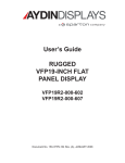
USER’S MANUAL for the Model 4419A1 19 INCH AMLCD FLAT PANEL COLOR MONITOR P/N 356-7067-501 Doc. No. 150-4419-004 (–), February 2015 NOTICE This manual is subject to change without notice and should not be construed to be a commitment in any form by Aydin Displays. Aydin Displays reserves the right to make improvements to the product at any time. It is understood that the delivered product will be of the latest possible design and that it may not be exactly as stated herein. This manual may contain descriptions of functions not implemented at time of distribution, unless prior contractual arrangements have been made. Aydin Displays reserves the right to modify or revise the content of this manual. It is further understood that in consideration of the receipt or purchase of this manual, the recipient or purchaser agrees not to reproduce, disseminate the information herein, or copy it by any means whatsoever or to permit such actions by others, for any purpose, without the written permission of Aydin Displays. All trademarks and registered trademarks are recognized as the property of their respective owners. Doc. No. 150-4419-004 (–), February 2015 150-4419-004 Rev – ii WARNING ! TO PREVENT FIRE OR SHOCK HAZARDS, DO NOT EXPOSE THIS UNIT TO RAIN OR MOISTURE. ALSO DO NOT USE THIS UNIT’S POLARIZED PLUG WITH AN EXTENSION CORD RECEPTACLE OR OTHER OUTLETS UNLESS THE PRONGS CAN BE FULLY INSERTED. DO NOT OPEN THE CABINET. THERE ARE HIGH VOLTAGE COMPONENTS INSIDE. REFER SERVICING TO QUALIFIED SERVICE PERSONNEL. CAUTION ! RISK OF ELECTRIC SHOCK. DO NOT OPEN. CAUTION: TO REDUCE THE RISK OF ELECTRIC SHOCK, DO NOT REMOVE COVER OR BACK, NO USER-SERVICEABLE PARTS INSIDE. REFER SERVICING TO QUALIFIED SERVICE PERSONNEL. This symbol warns the user that un-insulated voltage within the unit may be large enough to cause electric shock. Therefore, it is dangerous to touch any part inside the unit. ! 150-4419-004 Rev – This symbol alerts the user that important literature about the operation and maintenance of this unit has been included. Read it carefully to avoid any problems. iii PRODUCT SAFETY PRECAUTIONS Follow all warnings and instructions marked on the display. Do not attempt to service this display yourself. Removing the display cover or back may expose you to dangerous voltage or other risks. Refer all servicing to qualified service personnel. Adequate ventilation must be maintained to ensure reliable and continued operation and to protect the display from overheating. Do not block ventilation slots and openings or install the display in a place where ventilation may be hindered. This display should be operated from the type of power source indicated on the displays rating label. Do not allow metal pieces or objects of any kind to fall into the display through the ventilation holes. 150-4419-004 Rev – iv Thank you for purchasing this Aydin Displays LCD Display. The carton contains the items listed below: 150-4419-004 Rev – • 4419A1 LCD Display • Product CD containing: – This User’s Guide – Warranty Guide v Table of Contents 1 2 3 4 5 6 7 8 Introduction .............................................................................................................. 1 CONNECTIONS....................................................................................................... 1 2.1 Inputs ................................................................................................................ 1 2.1.1 Power......................................................................................................... 1 2.1.2 DVI ............................................................................................................. 1 2.1.3 Analog R-G-B ............................................................................................ 1 Display Setup ........................................................................................................... 2 Front Panel Buttons/On-Screen Display .................................................................. 2 4.1 Front Panel Buttons .......................................................................................... 2 4.2 OSD Menu ........................................................................................................ 3 4.2.1 Input Select ................................................................................................ 3 4.2.2 Setup ......................................................................................................... 3 4.2.3 Color Adjust ............................................................................................... 4 4.2.4 Picture Adjust............................................................................................. 4 4.2.5 Tool Box..................................................................................................... 5 4.2.6 Exit OSD Menu .......................................................................................... 5 4.2.7 OSD MENU – SAMPLE IMAGES .............................................................. 6 4419A1 SPECIFICATIONS ...................................................................................... 8 5.1 LCD Module ...................................................................................................... 8 5.2 RGB Video Input Signal .................................................................................... 8 5.3 DIGITAL Video Input Signal .............................................................................. 8 5.4 Refresh Rate ..................................................................................................... 8 5.5 Backlight Brightness ......................................................................................... 8 5.6 Dimming Range ................................................................................................ 8 5.7 VESA Resolutions Supported ........................................................................... 9 5.8 Power Consumption.......................................................................................... 9 5.9 Dimensions ....................................................................................................... 9 5.10 Weight ............................................................................................................... 9 5.11 Operating Environment ................................................................................... 10 5.12 Non-Operating Environment ........................................................................... 10 Maintenance .......................................................................................................... 11 6.1 Preventive Maintenance ................................................................................. 11 6.1.1 Surface Cleaning ..................................................................................... 11 6.1.2 Image Persistence ................................................................................... 11 6.2 CORRECTIVE MAINTENANCE ..................................................................... 11 6.3 Troubleshooting (No Picture) .......................................................................... 12 4419A1 DISPLAY DIMENSIONS ........................................................................... 13 4419A1 wall mount kit ............................................................................................ 15 150-4419-004 Rev – vi 1 INTRODUCTION The Model 4419A1 AMLCD Monitor is a 19” diagonal display with a native resolution of 1280 x 1024 (UXGA) pixels. The display is designed to operate from 115 VAC, 60Hz, single phase. Inputs are provided for DVI-D and VGA. Generally, all VESA compatible video formats are supported. If a mode isn’t supported, the factory can add special modes. 2 2.1 CONNECTIONS Inputs 2.1.1 Power Connector: IEC 60320 C14 Input Voltage: Universal AC Input Range 90-264 VAC Input Current: 0.61/0.32 Amps at 115/220VAC Input Frequency: 50/60 Hz Input Power: 45 W 2.1.2 DVI Connector: Single-Link DVI-D (Standard DVI pin-out) Bandwidth: Supports up to 162 MHz operation. 2.1.3 Analog R-G-B Connector: HD15 female (Standard VGA pin-out) Synchronization: Supports separate H & V sync, separate composite sync, and sync on green. 150-4419-004 Rev – 1 3 DISPLAY SETUP When the VGA input is connected (HD15 or BNC inputs), the display must be adjusted to accommodate the video input levels from the VGA source. This is done by displaying an image with full intensity Red, Green and Blue and performing an Auto Gain adjust followed by an Auto Adjust. 4 4.1 FRONT PANEL BUTTONS/ON-SCREEN DISPLAY Front Panel Buttons Press MENU to display the On-Screen-Display (OSD). Use the + and - buttons to move the cursor to the desired menu selection and press MENU to access the adjustment or function. With the EXIT button you can exit the current function and go back to the previous menu point. 150-4419-004 Rev – 2 BUTTON - OPERATION PERFORMED IF OSD NOT DISPLAYED Enables backlight brightness adjustment window OPERATION PERFORMED WHEN OSD DISPLAYED Selects next menu option or next sub-menu option or decrease selected value Selects previous menu option or previous sub-menu option or increase selected value + Video input select EXIT Performs auto adjust Exits sub-menu option or exits OSD SELECT Enables OSD Selects menu option or sub-menu option 4.2 OSD Menu Observe the following Top-Level Menu Selection Tabs on the OSD Menu: • • • • • • INPUT SETUP COLOR ADJUST PICTURE ADJUST TOOL BOX EXIT/SAVE INPUT SELECT is the default foreground menu; the active menu will always appear in the foreground. The Selection Tab of the active menu will be highlighted in blue. See the OSD – SAMPLE IMAGES section of this document for sample images of OSD menus. 4.2.1 Input Select Selects the input source for the LCD display. If the OSD is not visible, press the front panel “SELECT” key once to activate the OSD. Observe the following choices in the input select List: • • VGA DVI 4.2.2 Setup The following adjustments are provided under the Setup Menu tab: • • • • 150-4419-004 Rev – Brightness Contrast Black level EXIT 3 4.2.3 Color Adjust The following adjustments are provided under the Color Adjust Menu tab: • • • • Auto Color sRGB Adjust Color Temperature EXIT 4.2.4 Picture Adjust NOTE: Image adjust is pattern sensitive. The pattern should contain a border around the entire image and high frequency data content i.e. SMPTE133. A typical Image adjustment procedure would be: For picture width: Display an image with a border. Select the Clock adjustment and increase the picture width until one side of the image goes off the screen. Using the Hor. Position adjustment, center the image on the screen. Select the Clock adjustment again and increase the picture width until the image goes off the screen. Repeat this sequence until the image is centered and fills the screen. For phase adjustment: Display an image with high frequency content. Select and adjust the phase until the high frequency image content is homogeneous. The following adjustments are provided under the Picture Adjust Menu tab: • • • • • • 150-4419-004 Rev – Auto Position Width Adjust Phase Adjust Horizontal Pos Vertical Pos EXIT 4 4.2.5 Tool Box The following adjustments are provided under the Tool Box Menu tab: • • • • • • • OSD Factory Reset Factory Reset Color Factory Reset Position Sharpness Adjust 640 x 720 EXIT 4.2.6 Exit OSD Menu Displays Resolution. 150-4419-004 Rev – 5 4.2.7 OSD MENU – SAMPLE IMAGES INPUT SELECT (VGA) INPUT SELECT (DVI) SETUP COLOR ADJUST PICTURE ADJUST (VGA) TOOL BOX 150-4419-004 Rev – 6 EXIT OSD MENU 150-4419-004 Rev – 7 5 4419A1 SPECIFICATIONS 5.1 LCD Module 5.2 RGB Video Input Signal 5.3 Horizontal: 24.8 kHz to 91 kHz Vertical: 47.2 Hz to 89 Hz Backlight Brightness 5.6 Digital Visual Interface DVI-D as defined by the Digital Display Working Group Refresh Rate 5.5 Video: Analog 0 to 0.8 Vp-p (0.7 Vp-p/75 Ohms) Sync: Separate Sync TTL Level; Horizontal Sync Positive/Negative; Vertical Sync Positive/Negative; Composite Sync Positive/Negative, TTL Level; Sync on Green Video (Positive) 0.7 Vp-p and sync Negative 0.3 Vp-p DIGITAL Video Input Signal 5.4 Active matrix thin film transistor (TFT) liquid crystal display (LCD) Native Resolution (Pixel Count): 1280 (H) x 1024 V) Pixel pitch: 0.294 mm (H) x 0.294 mm (V) Aspect Ratio: 5:4 Viewing angle: ±89° (typical all directions with more than 10:1 contrast ratio) Contrast Ratio: 1000:1 typical (dark environment) Display colors: 16,777,216 Dimming Range: 0% to 100% Diagonal: 19-IN nominal Viewable Image Size: 376.32mm (14.8-IN) H, 301.05mm (11.85-IN) V nominal 300 cd/m2 minimum Dimming Range Full dimming 150-4419-004 Rev – 8 5.7 VESA Resolutions Supported NOTE Resolution is based on horizontal and vertical frequencies only. 5.8 MODE # VIDEO MODE INPUT Vertical Refresh Rate Horizontal Frequency Pixel Frequency Standard Mode 1 640 x 400 85 Hz 37.9 KHz 31.500 MHz DOS 2 640 x 480 60 Hz 31.5 KHz 25.175 MHz VGA 3 640 x 480 72 Hz 37.9 KHz 31.500 MHz VGA 4 640 x 480 75 Hz 37.5 KHz 31.500 MHz VGA 5 640 x 480 85 Hz 43.3 KHz 36.000 MHz VGA 6 720 x 400 85 Hz 37.9 KHz 35.500 MHz VGA 7 800 x 600 56 Hz 35.1 KHz 36.000 MHz SVGA 8 800 x 600 60 Hz 37.9 KHz 40.000 MHz SVGA 9 800 x 600 72 Hz 48.1 KHz 50.000 MHz SVGA 10 800 x 600 75 Hz 46.9 KHz 49.500 MHz SVGA 11 800 x 600 85 Hz 53.7 KHz 56.250 MHz SVGA 12 1024 x 768 60 Hz 48.4 KHz 65.000 MHz XGA 13 1024 x 768 70 Hz 56.5 KHz 75.000 MHz XGA 14 1024 x 768 75 Hz 60.0 KHz 78.750 MHz XGA 15 1024 x 768 85 Hz 68.7 KHz 94.500 MHz XGA 16 1280 x 1024 60 Hz 64.0 KHz 108.000 MHz SXGA Power Consumption 5.9 Input 115 VAC 60Hz single-phase at 0.82 Amps, 40 W (typ.) Dimensions See the dimension drawings at the back of this User’s Guide. 5.10 Weight Panel (19-in): 150-4419-004 Rev – 11 lbs Nominal 9 5.11 Operating Environment Temperature: Humidity: Shock: Vibration: Drip Proof: Altitude: Sand and Dust: 5.12 0°C to 40°C; MIL-STD-810G Method 501/502, Procedure II 5% to 85% non-condensing; MIL-STD-810G, Method 507, Procedure I MIL-S-901D, Grade B, Class I, Type A MIL-STD-167-1A, Type I MIL-STD-810G, Method 506, Procedure II, Front Panel Only MIL-STD-810G, Method 500, Procedure II, 0 - 15,000 feet above sea level MIL-STD-810G, Method 510, Procedures I & II, Front Panel Only Non-Operating Environment Temperature: Altitude: 150-4419-004 Rev – -20°C to +60°C; MIL-STD-810G, Method 501/502, Procedure I MIL-STD-810G, Method 500, 0 - 40,000 ft. above sea level 10 6 MAINTENANCE 6.1 Preventive Maintenance The only periodic maintenance recommended is EXTERIOR SURFACE cleaning when necessary. 6.1.1 Surface Cleaning The window and exterior surfaces may be cleaned with isopropyl alcohol followed by distilled water rinse, applied with a soft cloth to avoid scratching the anti-reflective coating on the glass panel. NOTE: INTERIOR CLEANING OF THE MONITOR IS NEITHER REQUIRED NOR RECOMMENDED. 6.1.2 Image Persistence Image persistence is the occurrence of a ghost image that remains on the display screen even after the display monitor has been turned off. Unlike cathode ray tube monitors that permanently burn the image into the phosphors, with liquid crystal displays, image persistence is not permanent. LCD’s suffering from image persistence can be cleared by turning off the display monitor for a period equivalent to the duration in time that the offending image was displayed. If the image was displayed for one hour, turn the monitor off for one hour to erase the ghost image. NOTE: The use of a screen saver is recommended whenever the screen is idle. 6.2 CORRECTIVE MAINTENANCE Any corrective maintenance should be deferred to the depot or factory. 150-4419-004 Rev – 11 6.3 Troubleshooting (No Picture) 1. If no front panel indicators are lit, the most likely cause is no power input: a) Is power connected? (Make sure the power cord is fully seated.) b) Is the POWER switch ON? c) Is the fuse OK? 2. If the Yellow NO SYNC indicator is lit, most likely the monitor is not receiving a video input or that video input is not selected as the Main Picture Channel Input. (See section 3.1.1) 3. If the OUT OF RANGE indicator is lit, most likely the monitor is not receiving a valid format. 150-4419-004 Rev – 12 7 4419A1 DISPLAY DIMENSIONS For clarity, displays are shown without signal and power cables. 150-4419-004 Rev – 13 4419A1 DISPLAY DIMENSIONS CONT. 150-4419-004 Rev – 14 8 4419A1 WALL MOUNT KIT 150-4419-004 Rev – 15 4419A1 WALL MOUNT KIT CONT. 150-4419-004 Rev – 16