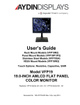
1
User’s Guide
RUGGED
VFP19-INCH FLAT
PANEL DISPLAY
VFP19R2-000-602
VFP19R2-000-607
Document No. 150-VFP9-104 Rev. (A), JANUARY 2008
NOTICE
This manual is subject to change without notice and should not be construed to be a
commitment in any form by Aydin Displays.
Aydin Displays reserves the right to make improvements to the product at any time. It is
understood that the delivered product will be of the latest possible design and that it may not
be exactly as stated herein. This manual may contain descriptions of functions not
implemented at time of distribution, unless prior contractual arrangements have been made.
Aydin Displays reserves the right to modify or revise the content of this manual. It is further
understood that in consideration of the receipt or purchase of this manual, the recipient or
purchaser agrees not to reproduce, disseminate the information herein, or copy it by any means
whatsoever, nor to permit such actions by others, for any purpose, without the written
permission of Aydin Displays.
All trademarks and registered trademarks are recognized as the property of their respective
owners.
Document No. 150-VFP9-104 Rev. (A)
2
FEDERAL COMMUNICATIONS COMMISSION REQUIREMENTS
This device complies with part 15 of the FCC Rules. Operation is subject to the following two
conditions: (1) This device may not cause harmful interference, and (2) this device must
accept any interference received, including interference that may cause undesired operation.
♦
Use the specified cables with the VFP19 display so as not to interfere with radio and television
reception.
♦
Use the supplied power cable or equivalent to ensure FCC compliance
♦
Use the shielded video cable
♦
Series VFP19 products have been tested and found to comply with the limits for Class A,
pursuant to part 15 of FCC rules. These limits are designed to provide reasonable protection
against harmful interference in a residential installation. This equipment generates, uses and
can radiate radio frequency energy and, if not installed and used in strict accordance with the
instructions, may cause harmful interference to radio communications. However, there is no
guarantee that interference will not occur in a particular installation. If this equipment does
cause harmful interference to radio or television reception, which can be determined by turning
the equipment off and on, the user is encouraged to try to correct the interference by one or
more of the following measures:
♦
Reorient or relocate the receiving antenna
♦
Increase the separation between the equipment and the receiver
♦
Connect the equipment into an outlet on a circuit different from that to which the receiver is
connected
♦
Consult the dealer or an experienced radio/TV technician for help
Document No. 150-VFP9-104 Rev. (A)
3
WARNING
!
TO PREVENT FIRE OR SHOCK HAZARDS, DO NOT EXPOSE THIS UNIT TO RAIN OR MOISTURE.
ALSO DO NOT USE THIS UNIT’S POLARIZED PLUG WITH AN EXTENSION CORD RECEPTACLE OR
OTHER OUTLETS UNLESS THE PRONGS CAN BE FULLY INSERTED.
DO NOT OPEN THE CABINET. THERE ARE HIGH VOLTAGE COMPONENTS INSIDE. REFER
SERVICING TO QUALIFIED SERVICE PERSONNEL.
CAUTION
!
RISK OF ELECTRIC SHOCK. DO NOT OPEN.
CAUTION: TO REDUCE THE RISK OF ELECTRIC SHOCK, DO NOT REMOVE COVER OR BACK, NO
USER-SERVICEABLE PARTS INSIDE. REFER SERVICING TO QUALIFIED SERVICE PERSONNEL.
This symbol warns the user that uninsulated voltage within the unit
may be large enough to cause electric shock. Therefore, it is
dangerous to touch any part inside the unit.
!
Document No. 150-VFP9-104 Rev. (A)
This symbol alerts the user that important literature about the
operation and maintenance of this unit has been included. Read it
carefully to avoid any problems.
4
PRODUCT SAFETY PRECAUTIONS
♦
The socket-outlet of power supply shall be installed near the equipment and shall be easily accessible.
♦
Follow all warnings and instructions marked on the display.
♦
Do not attempt to service this display yourself. There are no user replaceable parts inside and removing
the display cover or back will expose you to dangerous voltage or other risks. Refer all servicing to
qualified service personnel.
♦
Adequate ventilation must be maintained to ensure reliable and continued operation and to protect the
display from overheating. Do not block ventilation slots and openings or install the display in a place
where ventilation may be hindered.
♦
To protect from electrical shock, unplug the display’s power supply from the wall outlet before
relocating.
♦
Do not expose this display to direct sunlight or heat. Hot air may cause damage to the cabinet and other
parts.
♦
This display should be operated from the type of power source indicated on the display’s rating label.
♦
Do not allow metal pieces or objects of any kind to fall into the display through the ventilation holes.
♦
The inside of the fluorescent tube located within the LCD monitor contains mercury. Please follow the
bylaws or rules of your municipality to dispose of the tube properly.
♦
Do not use this display near water.
♦
Do not place any heavy objects on the power cord. Damage to the cord may cause shock or fire.
♦
When operating the LCD monitor with its AC 220-240V power supply; use a power cord that matches
the power supply voltage of the AC outlet being used. The power supply cord you use must have been
approved by and comply with the safety standards of your country.
♦
In UK, use a BS-approved power cord with molded plug having a black (5A) fuse installed for use with
this monitor.
♦
Unplug this display’s power supply from the wall outlet and refer servicing to qualified service
personnel in the event that:
Power cord or plug is damaged or frayed.
Liquid is spilled into the display or the display is exposed to rain or water.
The display does not operate normally when the operating instructions are followed.
The display has been dropped or the cabinet damaged.
The display exhibits a distinct change in performance, indicating a need for service.
Document No. 150-VFP9-104 Rev. (A)
5
Thank you for purchasing the Aydin Displays VECTOR Display.
This carton contains the items listed below:
♦
VFP19 LCD Display
♦
10 foot Power cord
♦
10 foot HD15(M) to HD15(M) Video Cable
♦
10 foot DVI-D(M) to DVI-D(M) Video Cable
♦
Product CD containing:
♦
-
This User’s Guide
-
Waraanty Guide
Mounting hardware (if applicable)
Please check the carton and its content for damage that may have occurred during shipment.
Report any damage to the shipping agent immediately and do not operate the display if it
appears to have been damaged. All warranty returns must use the original shipping carton and
packaging materials to prevent shipping damage.
Document No. 150-VFP9-104 Rev. (A)
6
DISPLAY CONNECTIONS AND ADJUSTMENTS:
If you have any problems connecting, setting up, or operating the display, please refer to the
Troubleshooting section of this guide.
DVI-D VIDEO Connector:
This input is used for Digital Video input, connect one end of the supplied DVI-D video cable to the
DVI-D connector on the rear of the display and the other end to a DVI-D connector on the video source.
HD15 VIDEO Connector:
This input is used for VGA Analog Video input, connect one end of the supplied VGA video cable to
the HD15 connector on the rear of the display and the other end to a HD15 connector on the video
source.
Plug the power cord into the rear of the display and then plug the cord into an AC power source. The
RED LED indicator will light. Turn on the display by pressing the ON/OFF button on the front panel.
The Green ON LED will light. If the RED (NO SYNC) LED is lit, refer to the Troubleshooting section.
CONTROLS:
Hot Buttons:
The following HOT Buttons are enabled when the OSD is NOT selected:
MUTE
UP, DOWN
AUTO ADJ
VIDEO
- Enables or disables the audio.
- Adjusts the audio volume
- Adjusts the image position, Horz. size, Vert. Size, and Fine settings.
- Sequentially search through all the video inputs until a video signal is detected.
On-Screen-Menu (OSM) Controls:
The OSM controls on the front of the monitor function as follows:
To access OSM menu, press the OSD/ENTER Button.
To change the video input signal source, press the VIDEO button when OSM is NOT selected.
Control
Main Menu
Sub-Menu
Value/ADJ BAR
MUTE/EXIT
Exits the OSM menu.
Exits to the OSM main menu
Exits to Sub-menu
OSD/ENTER
Enables the OSD Menu
Selects the adjustment bar or
Value selections.
N/A
UP, DOWN
Moves the highlighted area up/down
to select desired sub-menus.
Moves the highlighted area up
or down to select the desired
adjustment function.
Moves the bar left/right to
increase or decrease the
selected adjustment, or
select different values.
VIDEO
N/A
N/A
N/A
RESET
Resets all controls to
Factory-default values.
Note: When “RESET” is pressed, a warning will appear allowing you to cancel the reset function by pressing the EXIT button.
Document No. 150-VFP9-104 Rev. (A)
7
BRIGHTNESS/CONTRAST CONTROLS:
BRIGHTNESS:
Adjusts the overall image and background screen brightness.
CONTRAST:
Adjusts the image brightness in relation to the background.
SHARPNESS:
This function uses digital technology to keep a crisp image at any timing. Sharpness is independent from other
settings and can be adjusted continuously to get a distinct or soft image.
DIMMING:
This function adjusts the output level of the Backlight.
AUTO ADJUST (Analog input only):
Automatically adjusts the Image Position, the Horizontal Size (or V Size), and Fine settings.
IMAGE CONTROLS (ANALOG INPUT ONLY):
If the ‘AUTO Adjust function’ does not display a satisfactory picture, further tuning can be performed using the following manual
adjustments.
H. POSITION:
Adjusts the horizontal position by increasing or decreasing this setting.
V. POSITION:
Adjusts the vertical position by increasing or decreasing this setting.
PHASE (ANALOG INPUT ONLY):
Improves focus, clarity and image stability by increasing or decreasing this setting.
FREQUENCY (CLOCK):
Adjusts the horizontal size by increasing or decreasing this setting.
COLOR SETTING:
TEMPERATURE:
Sets Color Temperature to either of three standards or can be USER adjusted using the R, G, B controls below.
RED:
Adjusts RED color video level highlights.
GREEN:
Adjusts GREEN color video level highlights.
Document No. 150-VFP9-104 Rev. (A)
8
BLUE:
Adjusts BLUE color video level highlights.
AUTO COLOR:
Adjusts the gain of the amplitude on the video input signal.
AUDIO CONTROLS:
VOLUME:
Adjusts the level of the audio output.
MUTE:
Enables and disables the audio output.
OSD SETTING:
H POSITION:
Adjusts the horizontal position of the OSD by increasing or decreasing this setting.
V. POSITION:
Adjusts the vertical position of the OSD by increasing or decreasing this setting.
OSD TRANSPARENCY:
Adjusts the background of the OSD from opaque to transparent.
OSD TIMEOUT:
Set the auto timeout for the OSD
CLEANING AND CARE OF PROTECTIVE DISPLAY LENS:
•
•
Always damp-dust the acrylic protective lens. For best results, mix a solution of one teaspoon of mild
dishwashing liquid and one pint of water. Apply this solution with spray bottle and wipe dry with a clean
cotton cloth.
Do-Not Use: Window cleaning fluids, scouring compounds, gritty cloths, leaded or ethyl gasoline or strong
solvents such as alcohol, acetone, carbon tetrachloride, etc.
Document No. 150-VFP9-104 Rev. (A)
9
VECTOR 19 SPECIFICATIONS:
Visual Performance:
Diagonal:
19 inch TFT Active-Matrix LCD
Active Display Area:
Horiz.: 396.32mm
Vert.: 301.056
Pixel Pitch:
0.294 mm
Luminance:
300cd/m2 (typical)
Contrast Ratio:
1300:1 (typical)
Resolutions Supported:
Landscape:
720x400
640 x 480
800 x 600
1024 x 768
1152 x 900
1280 x 1024
@ 75 Hz
@ 60-75 Hz
@ 60-75 Hz
@ 60785 Hz
@ 66, 76 Hz
@ 60-75 Hz (Analog)
Input Signal:
Video:
Analog input, 0.7 Vp-p/75 Ohms
Digital input, DVI-D
Sync:
Separate Sync TTL Level
Horizontal Sync Positive/Negative
Vertical Sync Positive/Negative
Composite Sync Positive/Negative
Sync on Green Video 0.7 Vp-p and sync Negative 0.3 Vp-p
Digital:
Analog:
DVI-D
HD15 VGA
Input:
Scanning Frequency:
Horizontal:
Vertical:
View Angle:
+/-890 all directions
Response Time:
20ms (Typ., on/off)
Document No. 150-VFP9-104 Rev. (A)
31 to 82 kHz
50 to 85Hz
10
Environmental:
Operating Temperature:
0°C to 40°C
Storage Temperature:
-20°C to 60°C
Operating Humidity (Non-condensing):
30% to 80%
Storage Humidity: (Non-condensing):
10% to 90%
Operating Altitude:
0 to 12,000 ft
Storage Altitude:
0 to 40,000 ft
Shock:
20G, ½ Sine, 11ms pulse
Vibration:
0. 015-in. p-p, 5-53Hz Sine,
2Gpk, 53-640Hz Sine
Power Supply:
Internal 115VAC/220VAC, 50/60Hz
Current Rating:
0.57A @ 115VAC/0.28A @ 220VAC
Weight:
15.9lbs
EMI:
FCC Class A
Power:
41 Watts
Document No. 150-VFP9-104 Rev. (A)
11
TROUBLESHOOTING:
NO PICTURE:
•
•
•
If the RED LED is lit, verify the FPD is powered on.
If the RED LED is lit, verify that the signal cable is properly connected to the display and computer.
The Green ON LED should be lit.
IMAGE PERSISTENCE:
•
Image persistence is when a “ghost” of an image remains on the screen even after the monitor has been turned
off. Unlike CRT monitors, LCD monitors’ image persistence is not permanent. To alleviate image
persistence, turn the monitor off for as long as an image was displayed. If an image was on the monitor for
one hour and a “ghost” of that image remains, the monitor should be turned off for one hour to erase the
image.
IMAGE IS UNSTABLE, UNFOCUSED OR SWIMMING IS APPARENT:
•
•
Signal cable (video) should be completely attached to the computer and display.
Use the OSM Image Adjust controls to focus and adjust display by increasing or decreasing the FINE setting.
When the display mode is changed, the OSM Image Adjust settings may need to be re-adjusted.
DISPLAY IMAGE IS NOT SIZED PROPERLY:
•
Use the OSM Image Adjust controls to increase or decrease the H. SIZE setting.
CUSTOMER SERVICE CONTACT INFORMATION:
Customer Service and Technical Support
Phone: 610-404-5370
E-mail: [email protected]
Document No. 150-VFP9-104 Rev. (A)
12
VFP19 RACK MOUNT FRONT AND REAR VIEWS
Document No. 150-VFP9-104 Rev. (A)
13