1
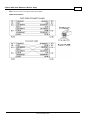
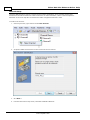
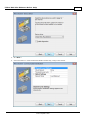
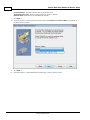
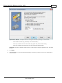
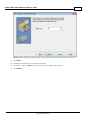
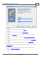
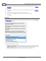
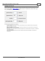
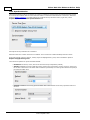
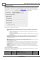
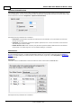
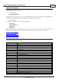
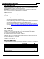
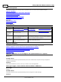
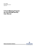
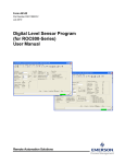
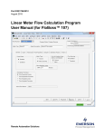
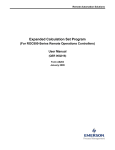
Fisher ROC Plus Ethernet
Driver Help
© 2015 Kepware, Inc.
Fisher ROC Plus Ethernet Driver Help
2
Table of Contents
Table of Contents
2
Fisher ROC Plus Ethernet Driver Help
5
Overview
5
Channel Setup
7
Device Setup
13
Scan Mode
15
Timings and Timeouts
16
Automatic Demotion
17
Automatic Tag Database Generation
18
Time Synchronization
19
Ethernet Settings
20
Tag Import Settings
21
Communication Specification
22
Operator Identification
23
EFM Meters
23
Data Types Description
25
Address Descriptions
26
ROC Plus Point Types
26
Logical / Location Details
27
User-Defined Point Types
28
User Table Points
28
Binary Field (BIN) Example
28
Error Descriptions
29
Error Reasons
29
Address Validation
29
Address <address> is out of range for the specified device or register.
29
Data type <type> is not valid for device address <address>.
29
Device address <address> contains a syntax error.
30
Device address <address> is read only.
30
Missing address.
30
Automatic Tag Database Generation Messages
30
Error importing CSV tag record <record number>: Address <address> is out of range for the
specified device or register.
30
Unable to generate a tag database for device <device>. Reason: <Error reason>.
31
Unable to generate a tag database for device <device>. Reason: Auto tag generation.
31
Unable to generate a tag database for device <device>. Reason: Error while reading from import file.
31
Unable to generate a tag database for device <device>. Reason: Error while reading from ROC system
31
file.
www. kepware.com
Fisher ROC Plus Ethernet Driver Help
3
Unable to generate a tag database for device <device>. Reason: Failed to open record set.
32
Unable to generate a tag database for device <device>. Reason: Import file <file name> not found.
32
Unable to generate a tag database for device <device>. Reason: Input file is corrupt.
32
Unable to generate a tag database for device <device>. Reason: Input file not found.
33
Unable to generate a tag database for device <device>. Reason: Low memory resources.
33
Unable to generate a tag database for device <device>. Reason: ROC system file <file name> not
found.
33
Unable to generate a tag database for device <device>. Reason: System DB file <file name> not
found.
33
33
Device-Specific Messages
<Device name> - Failed to read EFM pointer file. <Extended error>.
34
<Device name> - Failed to write EFM pointer file. <Extended error>.
34
Block read for point type <point type>, logical address <logical address>, parameter range <start
parameter - end parameter> of device <device name> failed. <Error reason>.
35
Block read for point type <point type>, logical address <logical address>, parameter range <start
parameter - end parameter> of device <device name> failed. Parameters are not in the loaded UDP
configuration.
35
Device <device> responded with error. (Tag <tag address>) - Details: <error code>.
35
Failed to obtain data block for point type = <point type>, logical address = <address>, starting
parameter = <starting parameter>, ending parameter <ending parameter> for device <device>.
Error = <ROC error code>.
35
Failed to write data for point type = <point type>, logical address = <address>, parameter =
<parameter> for device <device>. Error = <error code>.
36
Multiple batches completed since the previous batch history poll for meter <meter> on device
<device>. The last uploaded batch ticket number is <last ticket number> and the current batch
ticket number is <current ticket number>.
36
Operator identification failed for device <device name>. <Error reason>.
36
Read for point type <point type>, logical address <logical address>, parameter number <parameter
number> of device <device name> failed. <Error reason>.
37
ROC initialization error: Unable to read general configuration.
37
ROC initialization error: Unable to retrieve I/O map.
37
Serialization of EFM data to temporary file <file name> failed. Reason: <file I/O error>.
38
The username or password supplied was not accepted. Error = 6.
38
The username or password supplied was not accepted. Error = 63.
38
Time synchronization with device <device name> failed. <Error reason>.
38
Write failed with error code <error code> for the following tag(s) in device <device name>:<tag
list>.
39
Write for the following tags of device <device name> failed: <tag list>. <Error Reason>.
39
Write request rejected on read-only item reference <channel name> <device name> <address>.
39
39
Device Status Messages
<Device> may have incomplete history configured for meter <meter>.
39
Device <device name> is not responding.
40
EFM <type> upload for device <device name> meter <meter name> failed. Framing error.
40
Resetting the EFM cache for device <device>.
40
www. kepware.com
Fisher ROC Plus Ethernet Driver Help
4
40
User Configurable Table Messages
Block read for user table <table number>, location range <start location> - <end location> of device
<device name> failed. Device returned error code <error code>.
41
Block read for user table <table number>, location range <start location> - <end location> of device
<device name> failed. Framing error.
41
Block read for user table <table number>, location range <start location> - <end location> of device
<device name> failed. Locations are not configured in the user table.
41
Error parsing user table configuration on device <device name>. User table <table number>
contains an invalid user-defined point type, location, or parameter in table location <location
address>.
41
Error parsing user table configuration on device <device name>. User table <table number>
contains an invalid point type, location, or parameter in table location <location address>.
42
Read for user table <table number>, location <location address> of device <device name> failed.
Device returned error code <error code>.
42
Read for user table <table number>, location <location address> of device <device name> failed.
Framing error.
42
Read for user table <table number>, location <location address> of device <device name> failed.
Location is not configured in the user table.
42
User table configuration upload on device <device name> failed. Device not responding.
42
User table configuration upload on device <device name> failed. Device responded with error code
<error code>.
43
User table configuration upload on device <device name> failed. Framing error.
43
User table configuration upload on device <device name> failed. Internal error.
43
43
User-Defined Point Messages
Block read for point type <point type>, logical address <logical address>, parameter range <start
parameter - end parameter> of device <device name> failed. Parameters are not in the loaded UDP
configuration.
44
Read for point type <point type>, logical address <logical address>, parameter number
<parameter> of device <device name> failed. Parameter is not in the loaded UDP configuration.
44
Unable to parse the user-defined point configuration information for point type <point type> on
device <device name>.
44
User-defined point configuration upload for point type <point type>, logical address <logical
address>, parameter number <parameter> of device <device name> failed. <Error reason>.
44
45
ROC Plus Error Codes
Index
46
www. kepware.com
Fisher ROC Plus Ethernet Driver Help
5
Fisher ROC Plus Ethernet Driver Help
Help version 0.009
CONTENTS
Overview
What is the Fisher ROC Plus Ethernet Driver?
Channel Setup
How do I configure channels for use with this driver?
Device Setup
How do I configure a device for use with this driver?
Data Types Description
What data types does this driver support?
Automatic Tag Database Generation
How can tags be automatically created for this driver?
Address Descriptions
How do I address a data location on a Fisher ROC Plus Ethernet device?
Error Descriptions
What error messages does the Fisher ROC Plus Ethernet Driver produce?
Overview
The Fisher ROC Plus Ethernet Driver supports both real-time read and write access and historical Electronic Flow
Measurement (EFM) data access in ROC Plus Ethernet controllers. It is ideal for both local and remote
communications to RTUs, supporting the ability to serialize requests between multiple devices on remote serial
networks. Like all EFM-enabled drivers, the Fisher ROC Plus Ethernet Driver also supports time synchronization
and the interleaving of real-time and EFM data access. This ensures that no blackouts occur during EFM data
collection.
Access real-time data in ROC Plus Ethernet controllers via OPC client applications, including HMI, SCADA,
Historians, MES, ERP systems, and more. Export Gas and Liquid EFM data to Flow-Cal, PGAS, databases, and
other custom formats. For more information on scheduling and exporting EFM data from ROC Plus Ethernet
controllers, refer to the EFM Exporter Plug-In help documentation.
Note: For more information on the Opcodes, Point Types, and Parameters available in the ROC Plus protocol, refer
to the device's ROC Plus protocol user manual.
Supported Devices
ROC809
ROC827
ROC809L
ROC827L
Note: The ROC809L and ROC827L models support both Gas and Liquid EFM. The ROC809 and ROC827 models
only support Gas EFM.
Supported Protocol
ROC Plus
Liquid EFM Firmware Requirement
ROC800L (W68258) Firmware version 1.30 or later
User Program Requirements
Liquid Calcs version 1.03.00 (W68259) or later
Batching version 1.03.00 (W68260) or later
Maximum Number of Channels and Devices
The maximum number of supported channels is 1024. The maximum number of devices supported per channel
is 255.
www. kepware.com
Fisher ROC Plus Ethernet Driver Help
Note: This driver does not support Report by Exception.
Cable Connections
www. kepware.com
6
Fisher ROC Plus Ethernet Driver Help
7
Channel Setup
The Fisher ROC Plus Ethernet Driver supports Communication Serialization, which specifies whether data
transmissions should be limited to one channel at a time. For more information, refer to "Channel Properties Advanced" in the server help file. The maximum number of supported channels is 1024.
To create a new channel:
1. In the Project View, right-click and choose New Channel.
2. Accept the default channel name or enter a name for the new channel.
3. Click Next >.
4. From the Device Driver drop-down, select Fisher ROC Plus Ethernet.
www. kepware.com
Fisher ROC Plus Ethernet Driver Help
5. Click Next >.
6. In the New Channel - Communication Serialization wizard step, configure the channel.
www. kepware.com
8
Fisher ROC Plus Ethernet Driver Help
9
Virtual Network - Select the network name or the default, None
Transactions per cycle - Enter the target number or accept 1 (default).
Network Mode -Select Priority or Load Balanced (default).
7. Click Next >.
8. In the New Channel - Network Interface wizard step, select Default or Intel Pro/1000 (list is based on
the detected environment).
9. Click Next >.
10. In the New Channel - Write Optimizations wizard step, configure channel writes.
www. kepware.com
Fisher ROC Plus Ethernet Driver Help
10
Optimization Method - Accept the default or change the selection by clicking in a radio button.
l
Write all values for all tags (most data, most network traffic)
l
Write only the latest value for non-Boolean tags (least data, least network traffic)
l
Write only the latest value for all tags (key data, moderate network traffic)
Duty Cycle - Accept 10 (default) writes for every 1 read or adjust using the up/down arrows. The range
is 1-10.
11. Click Next >.
12. In the New Channel - Non-Normalized Float Handling wizard step, configure how non-normalized values
will be handled.
www. kepware.com
11
Fisher ROC Plus Ethernet Driver Help
Replaced with zero recognizes invalid outliers and eliminates them by replacing the value with integer
zero (default).
Unmodified allows values that are potentially invalid outliers into the data stream.
13. Click Next >.
14. In the New Channel - Inter-Device Delay wizard step, configure the time, in milliseconds, between
requests to devices.
www. kepware.com
Fisher ROC Plus Ethernet Driver Help
Delay Accept 0 milliseconds (default) or adjust using the up/down arrows. The range is 0-60000 ms.
15. Click Next >.
16. Review the configuration in the Summary wizard step.
17. If necessary, use the < Back button to return to previous steps to make changes.
18. Click Finish >.
www. kepware.com
12
Fisher ROC Plus Ethernet Driver Help
13
Device Setup
Once at least one channel is configured, devices using the Remote Operation Controllers (ROC) protocol can be
added for data collection and monitoring. The maximum number of devices supported on any one channel is 255.
Devices should be added to channels organized based on the channel configuration.
Adding a Device
To add a new device to a channel:
1. In the Project View, select the channel to contain the new device.
2. Select Click to add a device or right-click and choose New Device.
3. In the New Device - Name wizard step, accept the default channel name or enter a name for the new
device.
4. Click Next >.
5. From the Device Model drop-down, select the correct model for the device.
www. kepware.com
Fisher ROC Plus Ethernet Driver Help
14
6. Click Next >.
7. In the New Device - Scan Mode wizard step, configure the Scan Mode.
8. Click Next >.
9. In the New Device - Timing wizard step, configure the Timeouts and Timing.
10. Click Next >.
11. In the New Device - Auto-Demotion wizard step, configure how communication failure is handled.
12. Click Next >.
13. In the New Device - Database Creation wizard step, configure Automatic Tag Database Generation.
14. Click Next >.
15. In the New Device - Time Synchronization wizard step, configure timezone, DST, and synchronization.
16. Click Next >.
17. In the New Device - Communications Parameters wizard step, configure the Ethernet Settings.
18. Click Next >.
19. In the New Device - Tag Import Settings wizard step, identify and locate existing files to be included (see
Tag Import Settings)
20. Click Next >.
21. In the New Device - Communication Specification wizard step, identify the source and destination
addresses (see Communication Specification).
22. Click Next >.
www. kepware.com
Fisher ROC Plus Ethernet Driver Help
15
23. In the New Device - Operator Identification wizard step, configure the authorized user (see Operator
Identification).
24. Click Next >.
25. In the New Device - EFM Meters wizard step, add or update the meters for this device (see EFM Meters).
26. Click Next >.
27. In the New Device - Summary wizard step, review the configuration.
28. If necessary, use the < Back button to return to previous steps to make changes.
29. Click Finish >.
Scan Mode
Scan Mode settings are defined as a device is added and configured through the New Device wizard and can also
be modified after the device has been added. To define the Scan Mode settings for a new device, follow the steps
for Adding a Device. To modify settings on a defined device; select the device, right-click, select Properties,
and select the Scan Mode tab.
Descriptions of the parameters are as follows:
l
Respect client specified scan rate uses the polling frequency of the client requesting data (default).
l
Request data no faster than... sets a time, in milliseconds, to be the maximum frequency of polling.
l
Request all data at... sets an interval, in millisecond, when all tag information is collected.
l
Do not scan, demand poll only... allows a device to be polled by another process.
www. kepware.com
Fisher ROC Plus Ethernet Driver Help
16
Timings and Timeouts
Timings and Timeouts settings are defined as a device is added and configured through the New Device wizard
and can also be modified after the device has been added. To define the Timings and Timeout settings for a new
device, follow the steps for Adding a Device. To modify settings on a defined device; select the device, rightclick, select Properties, and select the Timing tab.
Descriptions of the parameters are as follows:
l
l
l
l
Connect timeout specifies the number of seconds before the server determines the connection has
failed. The default is 3 seconds.
Request timeout specifies the number of milliseconds before the server determines the a single poll
failed. The default is 3000 milliseconds.
Fail after specifies the number of consecutive attempts are considered a failed connection. The default is
3 successive timeouts.
Inter-request delay specifies the number of milliseconds between poll attempts. The default is 0
milliseconds.
www. kepware.com
Fisher ROC Plus Ethernet Driver Help
17
Automatic Demotion
Automatic Demotion settings are defined as a device is added and configured through the New Device wizard and
can also be modified after the device has been added. To define the Scan Mode for a new device, follow the steps
for Adding a Device. To modify settings on a defined device; select the device, right-click, select Properties
and select the Auto-Demotion tab.
Descriptions of the parameters are as follows:
l
l
l
l
Enable auto device demotion on communication failure - Allows communication to bypass a nonresponsive device and attempt data collection from other devices.
Demote after (n) successive failures - Defines the number of failed attempts at communication
before a device is bypassed. The default is 3.
Demote for (n) milliseconds - Configures the time, in milliseconds, the demoted device is bypassed to
allow other communication to occur. Once the delay expires, attempts to communicate with the device
resume. The default is 10000 milliseconds.
Discard write requests during the demotion period - Allows requests to be removed, rather than
queued, while the device is non-responsive and demoted.
www. kepware.com
Fisher ROC Plus Ethernet Driver Help
18
Automatic Tag Database Generation
This driver supports the server's Automatic Tag Database Generation feature. When enabled, a list of tags is built
within the server that correspond to the device's data points. To configure Automatic Tag Database Generation
settings, locate the Database Creation tab in device properties.
Note: For more information on importing tags from a ROCLINK project, refer to Tag Import Settings.
www. kepware.com
Fisher ROC Plus Ethernet Driver Help
19
Time Synchronization
Time Synchronization settings are defined as a device is added and configured through the New Device wizard
and can also be modified after the device has been added. To define the Scan Mode for a new device, follow the
steps for Adding a Device. To modify settings on a defined device; select the device, right-click, select
Properties, and select the Time Synchronization tab.
Descriptions of the parameters are as follows:
Select the time zone in which the device is installed. This is used for the data timestamps from the device.
If the environment (servers, devices, clients) adjust for Daylight Saving Time, click to enable the option to
Respect Daylight Saving Time.
There are three options for Synchronization Method:
l
l
l
Disabled allows device, client, and server times to be fully independent (default).
Absolute establishes a precise daily time when clocks in the environment (servers, devices, clients) are
forced to the same time. This allows data correlation by timestamp. Use the up/down buttons to specify if
the synchronization time.
Interval establishes a recurring synchronization of the environment clocks every specified number of
minutes.
www. kepware.com
Fisher ROC Plus Ethernet Driver Help
20
Ethernet Settings
Communications Parameters Ethernet Settings are defined as a device is added and configured through the New
Device wizard and can also be modified after the device has been added. To define the Ethernet Settings for a
new device, follow the steps for Adding a Device. To modify settings on a defined device; select the device,
right-click, select Properties, and select the Ethernet Settings tab.
Descriptions of the parameters are as follows:
l
l
l
l
Device address specifies the IP address or host name for communication with the device.
Port specifies the destination endpoint number for communication with the device. The default is port
4000. The range is 0-65535.
Close idle connection enables (Yes) / disables (No) the ability to terminate a connection that is no
longer active. The default is Yes.
Idle time before close (sec) defines the delay, in seconds, between a connection becoming idle and
being terminated. The default is 15 seconds. The range is 0-99 seconds.
www. kepware.com
Fisher ROC Plus Ethernet Driver Help
21
Tag Import Settings
A tag database can be created based on the device's configuration file or a ROCLINK 800 project file by bringing
those tags into the project with an import. Tag Import settings are defined as a device is added and configured
through the New Device wizard and can also be modified after the device has been added. To define the Tag
Import settings for a new device, follow the steps for Adding a Device. To modify settings on a defined device;
select the device, right-click, select Properties, and select the Tag Import Settings tab.
Descriptions of the parameters are as follows:
l
Import method: This option specifies the import method. Options include Online - from Device and
Offline - from Import File. The default setting is Online - from Device. Descriptions of the options are as
follows:
l
l
l
Online - from Device: This method automatically creates tags by polling the device for its
configuration and I/O data.
Offline - from Import File: This method automatically creates tags from a project file created
in ROCLINK 800.
Use legacy tag names: When checked, Automatic Tag Database Generation creates tags with names
consistent with the tags created in prior versions of the server. When unchecked, Automatic Tag
Database Generation creates tags with names consistent with the current version of the server. The
default setting is checked.
Note: For more information, refer to "Legacy vs. Non-Legacy Tag Names" below.
l
l
l
l
Tag import file: When pressed, this button invokes a dialog for locating the *.800 file that was created
using the ROCLINK800 software.
ROC system file: When pressed, this button invokes a dialog for locating the *.mdb file. This file is
usually named "ROC.mdb," and resides in the same folder where the ROCLINK 800 software is installed.
System DB file: When pressed, this button invokes a dialog for locating the *.mdw file. This file is
usually named "ROCLINK.mdw," and resides in the same folder where the ROCLINK 800 software is
installed.
Display Descriptions: When checked, this option includes the tag descriptions from the ROCLINK 800
master database.
Legacy vs. Non-Legacy Tag Names
For information on how legacy and non-legacy tag names are automatically generated based on the "Use legacy
tag names" option, refer to the table below.
Tag Type
Mode
Tag Name
Tag Address
Non-Boolean
Legacy
Non-Legacy
IPAddress_137_0
IP Address-137 (T137,L0,P1)
137-0.1
137-0.1
Boolean (.Bit)
Legacy
HighAlarm_41_0
41-0.16:2
www. kepware.com
Fisher ROC Plus Ethernet Driver Help
Non-Legacy
High Alarm-41 (T41,L0,P16) Bit 2
22
41-0.16:2
See Also: Automatic Tag Database Generation
Communication Specification
Communication Specification settings are defined as a device is added and configured through the New Device
wizard and can also be modified after the device has been added. To define the Communication Specification
settings for a new device, follow the steps for Adding a Device. To modify settings on a defined device; select
the device, right-click, select Properties, and select the Communication Specification tab.
Descriptions of the parameters are as follows:
l
l
l
l
l
Device address: This parameter specifies the device number of the remote ROC device. The valid range
is 1 to 255. The default setting is 240.
Device group: This parameter specifies the group number of the remote ROC device. The valid range is
1 to 255. The default setting is 240.
Host address: This parameter specifies the ROC unit number of the server. The valid range is 1 to 255.
The default setting is 1.
Host group: This parameter specifies the ROC group number of the server. The valid range is 1 to 255.
The default setting is 1.
Use Opcode 180 for read requests: This option should be used if few parameters from each point type
and logical address are typically used, as it yields more efficient communication. If unchecked, the driver
uses Opcode 167 to read entire point type logical addresses in one transaction. The default is unchecked.
www. kepware.com
Fisher ROC Plus Ethernet Driver Help
23
Operator Identification
This dialog is used to specify the operator identification values to be used when logging into the ROC Plus device
during initialization. To view or change the operator identification settings after the device has been added, rightclick on the device and select Properties | Operator Identification.
Descriptions of the parameters are as follows:
l
l
l
Username: This parameter specifies the authorized account identity. Three characters (as set in the
device) are required.
Password: This parameter specifies the operator password. Four numeric characters can be entered.
The valid range is 0000 to 9999.
Enable Access Level: When checked, this parameter specifies that the ROC Plus device has defined
access levels. The valid range is 0 to 5. The default setting is unchecked.
EFM Meters
EFM Meter settings are defined when a device is added and configured through the New Device wizard and can
also be modified at any time. To define the EFM Meter settings for a new device, follow the steps for Adding a
Device. To modify settings on a defined device; select the device, right-click, select Properties, and select the
EFM Meters tab.
Important:
The meter order in the EFM Meter List should match the order of the meters in ROCLINK 800.
Descriptions of the parameters are as follows:
www. kepware.com
Fisher ROC Plus Ethernet Driver Help
l
l
l
l
l
l
l
24
Non-Meter Events: This parameter specifies how non-meter EFM events are provided to EFM Exporters.
Options include Ignore, Broadcast, and Selected Meters. The default setting is Broadcast. Descriptions of
the options are as follows:
l
Ignore: This option does not send non-meter events for any meters.
l
Broadcast: This option sends non-meter events for all meters.
l
Selected Meters: This option only sends non-meter events for enabled meters.
EFM Meter List: This list view displays the meters that are currently supported by the device, including
the meter name and Non-Meter Event configuration. The information presented in this list view depends
on whether the Orifice, Gas Turbine, or Liquid Turbine tab is selected.
Note: The # column displays the actual meter number of each configured meter. This is the one-based
meter number that corresponds to the meter numbers the ROCLINK 800 configuration software used to
configure ROC devices.
Add: When clicked, this button opens the Meter Configuration dialog for adding a new meter to the
device.
Remove: When clicked, this button deletes the selected meter from the EFM Meter List.
Modify: When clicked, this button opens the Meter Configuration dialog for updating the selected meter
in the EFM Meter List.
Move Up: When clicked, this button updates the order, moving the selected meter up in the EFM Meter
List.
Move Down: When clicked, this button updates the order, the selected meter down in the EFM Meter
List.
Clear Cache on Next Upload
Users have the option to clear any cached EFM data from the device during the next upload. This feature also
removes pointer files, which are used to track EFM uploads to prevent uploading the same records twice. All EFM
data is re-uploaded. Once the cache is cleared, this parameter is automatically disabled. To enable this option,
open Device Properties | EFM Meters and click Clear cache on next upload. The default setting is
unchecked.
Meter Configuration
A maximum of twelve gas meters and six liquid meters can be configured for a device.
Descriptions of the parameters are as follows:
l
l
Meter Name: This parameter specifies the meter name. Each meter must be assigned a unique name.
Note: The default name depends whether an orifice or turbine meter is being created.
Receive Non-Meter Events: When checked, this option enables the meter to receive non-meter events.
Note: This option is only available when the Non-Meter Events parameter is set to Selected Meters.
Liquid Meter Record Timestamp Tolerance
Some ROC+ Liquid EFM meter configurations store station and meter data in separate history segments. The
Fisher ROC Plus Ethernet Driver uploads the data from both segments and merges it into a single historical record
based on timestamp.
Important: Data from each segment is not merged if the timestamps from each record are more than two
seconds apart. Data from each segment is included in different records; however, these records are most likely
incomplete.
www. kepware.com
Fisher ROC Plus Ethernet Driver Help
25
Data Types Description
Data Types
Description
Boolean
Single bit
Char
Signed 8-bit value
bit 0 is the low bit
bit 6 is the high bit
bit 7 is the sign bit
Byte
Unsigned 8-bit value
bit 0 is the low bit
bit 7 is the high bit
Short
Signed 16-bit value
bit 0 is the low bit
bit 14 is the high bit
bit 15 is the sign
Word
Unsigned 16-bit value
bit 0 is the low bit
bit 15 is the high bit
Word
HOURMINUTE
Point Type 100, parameters 3-5 are HOURMINUTE. This driver represents this data type as
Word.
Length: 2 Bytes. Time is listed as a decimal based number. The first two digits represent
the hour and the last two digits represent the minute.
Range: 9999, 0-23 for 2 MS Digits; 0-59 for 2 LS Digits
Special Meanings: 9999 = Disabled
DWord
Unsigned 32-bit value
bit 0 is the low bit
bit 31 is the high
Float
32-bit floating point value
bit 0 is the low bit
bit 31 is the high bit DWord
TLP
32-bit value: Point 'T'ype, 'L'ogical (or point number), and 'P'arameter number.* Three
bytes are used, but the top byte is not.
l
The type refers to the point type number.**
l
The location/logical number refers to individual points.
The parameter is a number assigned to each piece of data contained in a given point
type.
557158: BIN = 00001000 10000000 01100110. 01100110 = Point Type 102, 10000000 =
Location 128, 00001000 = Parameter 8.
l
DWord TLP
Example
The resulting TLP is 102-128.8
String
A linear group of ASCII characters with preserved whitespace (1 byte per character).
Date
The number of seconds since Jan 1 1970 @ 00:00:00.
Date Example
Date format:YYYY-MM-DDTHH:MM:SS.000.
2000-01-01T12:30:45.000
*For more information, refer to Logical/Location Details.
**For more information, refer to ROC Plus Point Types.
www. kepware.com
Fisher ROC Plus Ethernet Driver Help
26
Address Descriptions
ROC addresses are divided first by point type, logical address, and then by parameter index within the point type.
The general format is T-L.P, where:
l
T: The Point Type
l
L: The Logical Address
l
P: The Parameter Index
Parameters are blocked together on point type and logical address to a size up to 230 bytes. Some parameters are
broken down into individual bits. Those parameters are addressed as T-L.P:B, where:
l
B: The Bit Offset
For example, the address 1-50.3:2 indicates the following:
l
Point Type: 1
l
Logical Address: 50
l
Parameter: 3
l
Bit Offset: 2
Note: For a detailed listing of all point types' access, data type, length, and description, refer to the device's ROC
Plus protocol user manual. For more information on ROC addressing, select a link from the list below.
Logical / Location Details
ROC Plus Point Types
User-Defined Point Types
Binary Field (BIN) Example
ROC Plus Point Types
For a detailed listing of all point types' parameters, access, data type, length, and description; refer to the
device's ROC Plus protocol user manual.
Point Type
Description
82
Virtual Discrete Outputs
85
HART
91
System Variables
92
Login Parameters
95
Communication Ports
96
FST Parameters
97
FST Register Tags
98
Soft Point Parameters
99
Configurable Opcode Table
100
Power Control Parameters
101
Discrete Inputs
102
Discrete Outputs
103
Analog Inputs
104
Analog Outputs
105
Pulse Inputs
106
RTD
107
Thermocouple
108
Multi-Variable Sensor
109
System Analog Inputs
110
PID Control Parameters
111
Sampler/Odorizer Parameters
112
Station Parameters
113
Orifice Meter Run Configuration
114
Orifice Meter Run Values
115
Turbine Meter Run Configuration
www. kepware.com
Fisher ROC Plus Ethernet Driver Help
27
116
Turbine Meter Run Values
117
Modbus Configuration Parameters
118
Modbus Register to TLP Mapping
119
Modbus Event, Alarm and History Table
120
Modbus Master Modem Configuration
121
Modbus Master Table
122
DS800 Configuration
123
Security -- Group Configuration
124
History Segment Configuration
125
History Segment 0 Point Configuration
126
History Segment 1 Point Configuration
127
History Segment 2 Point Configuration
128
History Segment 3 Point Configuration
129
History Segment 4 Point Configuration
130
History Segment 5 Point Configuration
131
History Segment 6 Point Configuration
132
History Segment 7 Point Configuration
133
History Segment 8 Point Configuration
134
History Segment 9 Point Configuration
135
History Segment 10 Point Configuration
136
ROC Clock
137
Internet Configuration Parameters
138
User C++ Host Parameters
139
Smart I/O Module Information
140
Alternating Current Input / Output
141
Advanced Pulse Module
142
History Segment 11
143
History Segment 12
144
Transactional History Configuration
145
Transactional History Point Configuration
177
IEC62591 Commissioned List
Logical / Location Details
Within each point type, individual points are referenced by a logical number or a location. The location used by
the ROC Plus protocol for point types 101 to 109 is based on a physical input or output (I/O) module and point
location. All other point types use a logical number and are numbered in sequence.
Note: The "L" in "TLP" references the logical / location scheme.
Physical Point Numbers 1 to 160
Point types 101 through 109 have location numbers for the field I/O. For diagnostic inputs, the scheme is as
follows:
l
l
Location numbers 16 to 160 are assigned to field I/O. For example, if there was an I/O module in slot 1
with 4 points on it, they would be points 16 through 19.
Location numbers 0 to 15 are assigned to the system I/O. For example, the five diagnostic points in a
ROC800-Series would be 0 through 4.
Logical Point Numbers 0 to 127
For all other point types (except 101-109), the logical number is 0 to x, where x is one less than the total number
of points that exist for that point type. For example, the 16 PIDs would be logical numbers 0 through 15.
Note: For a detailed listing of all point types' access, data type, length, and description, refer to the device's ROC
Plus protocol user manual.
www. kepware.com
Fisher ROC Plus Ethernet Driver Help
28
User-Defined Point Types
User-Defined Points (UDP) make user program data available to ROCLINK and OPC clients. They are generally
used for configuration purposes. When creating a UDP in the server, the server Configuration always sets the
data type to its default. The data type is later read live from the device.
Important: Users must reinitialize the server after upgrading the user program on a device; otherwise, the
server cannot access the new points available in the upgraded user program.
Supported Device Models
All ROC800 Series devices.
Supported User-Defined Point Range
60 to 78
196 to 254
Troubleshooting
To avoid potential issues, users should do the following:
l
l
l
l
Verify that the point type is within the supported UDP range.
If a client attempts to write to a UDP type when no UDP type tags have been read since the server started,
the write may fail with a Type Mismatch error. Always complete a read on UDP type tags before a write is
attempted.
Verify that the point type exists in one of the user programs installed on the device.
Check the Event Log for the following error message, which occurs if the server fails to parse the UDP
configuration: Unable to parse the user-defined point configuration information for point type
<point type> on device <device name>.
User Table Points
User tables, also called Opcode tables, provide the ability to map any Point Type parameters to tables in the
device. This driver has the ability to read and write data points in the user tables using Opcodes 10 and 11. The
syntax for user table tags is:
user_table-n.m where n is the user table number and m is the data point or location within that table.
The user table number and location number are zero-based.
For example, the first location in the first user table is: user_table-0.0.
Important: Users must increment the version number of the user table when making changes to the table
configuration. Failure to do so when making changes to the table while the server is actively reading user table
tags results in bad quality tags or erroneous data.
Supported User Table Point Range
user_table-0.0 to user_table-15.43
Binary Field (BIN) Example
The table below shows an example alarm code from an Analog Input Point Type. This is used to demonstrate how
a binary parameter is returned. A "1" in any bit indicates that it is active or enabled.
Response Code
Bit
Low Alarm
0
0
Low Low Alarm
0
1
High Alarm
0
2
High High Alarm
0
3
Rate Alarm
0
4
Not Used
0
5
Point Fail Alarm
0
6
Scanning Disabled Alarm
1
7
www. kepware.com
Fisher ROC Plus Ethernet Driver Help
29
Error Descriptions
The following categories of messages may be generated. Click on a link for a list of related messages.
Address Validation
Automatic Tag Database Generation Messages
Device-Specific Messages
Device Status Messages
User Configurable Table Messages
User-Defined Point Messages
See Also:
ROC Plus Error Codes
Error Reasons
Error Reasons
Error Reason Possible Cause
Solution
Device not
responding
For more information, see Device
<device name> is not
responding.
For more information, see Device <device name> is
not responding.
Device
responded
with error
code
The ROC Plus device responded
with an error code.
For more information, see ROC Plus Error Codes.
Framing error
The response packet from the ROC This error is very rare. If encountered, users should
device has data fields that are not check with the manufacturer to ensure that the ROC Plus
as per the protocol.
device is consistent with the protocol.
Operator
identification
error
The operator identification login
(with user ID and password)
failed.
Refer to the Event Log message that corresponds to the
operator identification failure.
Address Validation
The following messages may be generated. Click on the link for a description of the message.
Address <address> is out of range for the specified device or register.
Data type <type> is not valid for device address <address>.
Device address <address> contains a syntax error.
Device address <address> is read only.
Missing address.
Address <address> is out of range for the specified device or register.
Error Type:
Warning
Possible Cause:
A tag address that has been specified statically references a location that is beyond the range of supported
locations for the device.
Solution:
Verify that the address is correct; if it is not, re-enter it in the client application.
Data type <type> is not valid for device address <address>.
Error Type:
Warning
Possible Cause:
A tag address that has been specified statically has been assigned an invalid data type.
Solution:
www. kepware.com
Fisher ROC Plus Ethernet Driver Help
30
Modify the requested data type in the client application.
Device address <address> contains a syntax error.
Error Type:
Warning
Possible Cause:
A tag address that has been specified statically contains one or more invalid characters.
Solution:
Re-enter the address in the client application.
Device address <address> is read only.
Error Type:
Warning
Possible Cause:
A tag address that has been specified statically has a requested access mode that is not compatible with what the
device supports for that address.
Solution:
Change the access mode in the server application.
Missing address.
Error Type:
Warning
Possible Cause:
A tag address that has been specified statically has no length.
Solution:
Re-enter the address in the server application.
Automatic Tag Database Generation Messages
The following messages may be generated. Click on a link for a description of that message.
Error importing CSV tag record <record number>: Address <address> is out of range for the
specified device or register.
Unable to generate a tag database for device <device>. Reason: <Error reason>.
Unable to generate a tag database for device <device>. Reason: Auto tag generation.
Unable to generate a tag database for device <device>. Reason: Error while reading from import
file.
Unable to generate a tag database for device <device>. Reason: Error while reading from ROC
system file.
Unable to generate a tag database for device <device>. Reason: Failed to open record set.
Unable to generate a tag database for device <device>. Reason: Import file <file name> not found.
Unable to generate a tag database for device <device>. Reason: Input file is corrupt.
Unable to generate a tag database for device <device>. Reason: Input file not found.
Unable to generate a tag database for device <device>. Reason: Low memory resources.
Unable to generate a tag database for device <device>. Reason: ROC system file <file name> not
found.
Unable to generate a tag database for device <device>. Reason: System DB file <file name> not
found.
Error importing CSV tag record <record number>: Address <address> is out of
range for the specified device or register.
Error Type:
Warning
Possible Cause:
www. kepware.com
Fisher ROC Plus Ethernet Driver Help
31
An imported tag address specifies a location that is beyond the range of supported locations for the device.
Solution:
Verify that the address is correct; if it is not, re-enter it in the file being imported.
Unable to generate a tag database for device <device>. Reason: <Error
reason>.
Error Type:
Warning
Possible Cause:
The error occurred due to the specified error reason.
Solution:
The solution depends on the specified error reason.
See Also:
Error Reasons
Unable to generate a tag database for device <device>. Reason: Auto tag
generation.
Error Type:
Serious
Possible Cause:
1. The connection between the device and the host PC is intermittent.
2. The communication parameters for the connection are incorrect.
Solution:
1. Verify the cabling between the PC and the device.
2. Verify that the specified communication parameters match those of the device.
Unable to generate a tag database for device <device>. Reason: Error while
reading from import file.
Error Type:
Warning
Possible Cause:
1. The tag import file (*.800) is corrupt.
2. The specified file was not created using the ROCLINK 800 software.
Solution:
1. Ensure that the project is pointing to the correct import file.
2. Re-create the import file using the ROCLINK 800 software and then re-try the import.
Unable to generate a tag database for device <device>. Reason: Error while
reading from ROC system file.
Error Type:
Warning
Possible Cause:
www. kepware.com
Fisher ROC Plus Ethernet Driver Help
32
1. The ROC system file (*.mdb) is corrupt.
2. The specified file was not created using the ROCLINK 800 software.
Solution:
1. Ensure that the project is pointing to the correct ROC system file.
2. Re-install the ROCLINK 800 software to re-install the system file. Then re-try the import.
Unable to generate a tag database for device <device>. Reason: Failed to open
record set.
Error Type:
Warning
Possible Cause:
1. The project file is corrupt or does not exist.
2. The location of the ROC.MDB and/or ROCLINK.MDW files have been specified incorrectly.
Solution:
In the server project, right-click on the device and select Properties. Open the Tag Import Settings tab to
check the name of the project file to import.
See Also:
Tag Import Settings
Automatic Tag Database Generation
Unable to generate a tag database for device <device>. Reason: Import file
<file name> not found.
Error Type:
Warning
Possible Cause:
The import file cannot be found.
Solution:
Ensure that the tag import file (*.800) is present in the location specified in the Tag Import Settings tab of device
properties. In the server project, right-click on the device and select Properties. Open the Tag Import
Settings tab to review the settings and check the import file. This file must be accessible to the server's runtime.
Unable to generate a tag database for device <device>. Reason: Input file is
corrupt.
Error Type:
Warning
Possible Cause:
The import file is corrupt.
Solution:
In the server project, right-click on the device and select Properties. Open the Tag Import Settings tab to
review the settings and check the import file. If necessary, re-export the project file from within ROCLINK800.
See Also:
Tag Import Settings
Automatic Tag Database Generation
www. kepware.com
Fisher ROC Plus Ethernet Driver Help
33
Unable to generate a tag database for device <device>. Reason: Input file not
found.
Error Type:
Warning
Possible Cause:
The import file cannot be located.
Solution:
In the server project, right-click on the device and select Properties. Open the Tag Import Settings tab to
review the name of the project file to import.
See Also:
Tag Import Settings
Automatic Tag Database Generation
Unable to generate a tag database for device <device>. Reason: Low memory
resources.
Error Type:
Warning
Possible Cause:
The memory required for Automatic Tag Generation could not be allocated. The process is aborted.
Solution:
Close any unused applications and/or increase the amount of virtual memory. Try again.
Unable to generate a tag database for device <device>. Reason: ROC system
file <file name> not found.
Error Type:
Warning
Possible Cause:
The ROC system file cannot be found.
Solution:
Ensure that the ROC system file (*.mdb) is present in the location specified in the Tag Import Settings tab of
device properties. In the server project, right-click on the device and select Properties. Open the Tag Import
Settings tab to review the settings and check the import file.
Unable to generate a tag database for device <device>. Reason: System DB
file <file name> not found.
Error Type:
Warning
Possible Cause:
The system database file cannot be found.
Solution:
Ensure that the system database file (*.mdw) is present in the location specified in the Tag Import Settings tab of
device properties. This file must be accessible to the server's runtime. In the server project, right-click on the
device and select Properties. Open the Tag Import Settings tab to review the settings and check the import
file.
Device-Specific Messages
The following error/warning messages may be generated. Click on the link for a description of the message.
<Device name> - Failed to read EFM pointer file. <Extended error>.
<Device name> - Failed to write EFM pointer file. <Extended error>.
www. kepware.com
Fisher ROC Plus Ethernet Driver Help
34
Block read for point type <point type>, logical address <logical address>, parameter range <start
parameter - end parameter> of device <device name> failed. <Error reason>.
Device <device> responded with error. (Tag <tag address>)-Details: <error code>.
Failed to obtain data block for point type = <point type>, logical address = <address>, starting
parameter = <starting parameter>, ending parameter <ending parameter> for device <device>.
Error = <ROC error code>.
Failed to write data for point type = <point type>, logical address = <address>, parameter =
<parameter> for device <device>. Error = <error code>.
Multiple batches completed since the previous batch history poll for meter <meter> on device
<device>. The last uploaded batch ticket number is <last ticket number> and the current batch
ticket number is <current ticket number>.
Operator identification failed for device <device name>. <Error reason>.
Read for point type <point type>, logical address <logical address>, parameter number <parameter
number> of device <device name> failed. <Error reason>.
ROC initialization error: Unable to read general configuration.
ROC initialization error: Unable to retrieve I/O map.
Serialization of EFM data to temporary file <file name> failed. Reason: <file I/O error>.
Time synchronization with device <device name> failed. <Error reason>.
The username or password supplied was not accepted. Error = 6.
The username or password supplied was not accepted. Error = 63.
Write request rejected on read-only item reference <channel name> <device name> <address>.
Write failed with error code <error code> for the following tag(s) in device <device name>:<tag
list>.
Write for the following tags of device <device name> failed: <tag list>. <Error reason>.
<Device name> - Failed to read EFM pointer file. <Extended error>.
Error Type:
Warning
Extended Error:
When supplied by the operating system, this describes the file error that occurred.
Possible Cause:
1. A permission error was encountered when the EFM pointer cache was read.
2. The EFM pointer cache file is corrupt.
Solution:
The Fisher ROC Plus Ethernet Driver automatically generates a new EFM pointer file; however, the server re-polls
(uploading all EFM data) during the next EFM poll for meters in the device.
Note:
For more information, refer to the extended error.
<Device name> - Failed to write EFM pointer file. <Extended error>.
Error Type:
Warning
Extended Error:
When supplied by the operating system, this describes the file error that occurred.
Possible Cause:
1. The disk is full.
2. A permission error was encountered when the EFM pointer cache was written.
Solution:
The server attempts to update the EFM pointer file periodically, in addition to when the server is shutdown. If the
pointer file cannot be written, the server re-polls (uploading all EFM data) during the next EFM poll for meters in
the device.
www. kepware.com
Fisher ROC Plus Ethernet Driver Help
35
Note:
For more information, refer to the extended error.
Block read for point type <point type>, logical address <logical address>,
parameter range <start parameter - end parameter> of device <device name>
failed. <Error reason>.
Error Type:
Serious
Possible Cause:
The error occurred due to the specified error reason.
Solution:
The solution depends on the specified error reason.
See Also:
Error Reasons
Block read for point type <point type>, logical address <logical address>,
parameter range <start parameter - end parameter> of device <device name>
failed. Parameters are not in the loaded UDP configuration.
Error Type:
Serious
Possible Cause:
The user program that is associated with the specified parameters has been upgraded to a newer version.
Solution:
Reinitialize the server to access the new parameters available in the upgraded user program.
Device <device> responded with error. (Tag <tag address>) - Details: <error
code>.
Error Type:
Serious
Possible Cause:
1. The connection between the device and the host PC is intermittent.
2. The communication parameters for the connection are incorrect.
3. The value written is out of range.
4. The write was performed while in an incorrect setup area.
Solution:
1. Check the cabling between the PC and the device.
2. Verify that the specified communication parameters match those of the device.
See Also:
Device Setup
Failed to obtain data block for point type = <point type>, logical address =
<address>, starting parameter = <starting parameter>, ending parameter
<ending parameter> for device <device>. Error = <ROC error code>.
Error Type:
Serious
www. kepware.com
Fisher ROC Plus Ethernet Driver Help
36
Possible Cause:
1. An invalid tag address is used for the point in block.
2. The device is not responding.
Solution:
1. Consult the ROC error code reference for further information regarding the error code.
2. Verify the cabling between the PC and the device.
3. Confirm that all tags within this block exist on the device.
See Also:
ROC Plus Error Codes
Failed to write data for point type = <point type>, logical address =
<address>, parameter = <parameter> for device <device>. Error = <error
code>.
Error Type:
Serious
Possible Cause:
1. The address is incorrect.
2. The unit does not support the particular address point.
3. The privileges for the logged-in user do not permit this operation.
Solution:
1. Consult the ROC error code reference for further information regarding the error code.
2. Correct the address.
3. Confirm that the address is supported by the controller in use.
4. Supply an operator identification with sufficient privileges.
See Also:
ROC Plus Error Codes
Multiple batches completed since the previous batch history poll for meter
<meter> on device <device>. The last uploaded batch ticket number is <last
ticket number> and the current batch ticket number is <current ticket
number>.
Error Type:
Warning
Possible Cause:
Multiple batches have completed since the last time EFM batch data was polled for the specified meter.
Solution:
Fisher ROC+ devices only store the latest complete batch and current batch data. The meter should be polled at a
rate such that there is only a single batch completed between polls.
Operator identification failed for device <device name>. <Error reason>.
Error Type:
Serious
www. kepware.com
Fisher ROC Plus Ethernet Driver Help
37
Possible Cause:
The error occurred due to the specified error reason.
Solution:
The solution depends on the specified error reason.
See Also:
Error Reasons
Operator Identification
Read for point type <point type>, logical address <logical address>,
parameter number <parameter number> of device <device name> failed.
<Error reason>.
Error Type:
Serious
Possible Cause:
The error occurred due to the specified error reason.
Solution:
The solution depends on the specified error reason.
See Also:
Error Reasons
ROC initialization error: Unable to read general configuration.
Error Type:
Serious
Possible Cause:
The driver may not be receiving a response from the device.
Solution:
1. Ensure the device is physically connected and powered on.
2. Check that the COM port is working and configured properly at the channel level (in the server).
3. Check the device-level operator identification and address specification settings and verify that they are
correct.
See Also:
Operator Identification
Communication Specification
ROC initialization error: Unable to retrieve I/O map.
Error Type:
Serious
Possible Cause:
Access to the I/O map has been restricted for the current user.
Solution:
Check the operator identification settings (such as username, password, and access level) and verify that they
are correct.
See Also:
Operator Identification
www. kepware.com
Fisher ROC Plus Ethernet Driver Help
Serialization of EFM data to temporary file <file name> failed. Reason: <file
I/O error>.
Error Type:
Warning
Possible Cause:
1. The driver was unable to create the specified file directory.
2. The driver was unable to access the specified file.
Solution:
1. Verify that the disk has sufficient disk space.
2. Verify user permissions for the specified file directory.
The username or password supplied was not accepted. Error = 6.
Error Type:
Serious
Possible Cause:
An access level has been enabled on the device but not in the driver.
Solution:
Check the operator identification settings and ensure that the Enable Access Level checkbox is checked.
See Also:
Operator Identification
The username or password supplied was not accepted. Error = 63.
Error Type:
Serious
Possible Cause:
The access level that has been enabled on the device is lower than the operator's access level.
Solution:
Check the operator identification settings and ensure that the operator's access level is less than or equal to the
access level enabled in the device.
See Also:
Operator Identification
Time synchronization with device <device name> failed. <Error reason>.
Error Type:
Serious
Possible Cause:
The error occurred due to the specified error reason.
Solution:
The solution depends on the specified error reason.
See Also:
Error Reasons
www. kepware.com
38
Fisher ROC Plus Ethernet Driver Help
39
Write failed with error code <error code> for the following tag(s) in device
<device name>:<tag list>.
Error Type:
Serious
Possible Cause:
The ROC device responded with an error code.
Solution:
Consult the ROC Plus error code reference for further information regarding the error code.
See Also:
ROC Plus Error Codes
Write for the following tags of device <device name> failed: <tag list>.
<Error Reason>.
Error Type:
Serious
Possible Cause:
The error occurred due to the specified error Reason.
Solution:
The solution depends on the specified error Reason.
See Also:
Error Reasons
Write request rejected on read-only item reference <channel name> <device
name> <address>.
Error Type:
Warning
Possible Cause:
The driver attempted to write to read-only data in the ROC controller.
Solution:
Do not attempt to write to read-only points.
Note:
In some situations, the Automatic Tag Generation process identifies read-only data as read/write, based on the
configuration that the driver retrieved from the ROC controller and the ROC specification. Nonetheless, the ROC
controller itself is the final authority on whether data is writable. For more information, refer to the controller's
documentation.
Device Status Messages
The following error/warning messages may be generated. Click on the link for a description of the message.
<Device> may have incomplete history configured for meter <meter>.
Device <device name> is not responding.
EFM <type> upload for device <device name> meter <meter name> failed. Framing error.
Resetting the EFM cache for device <device>.
<Device> may have incomplete history configured for meter <meter>.
Error Type:
Warning
Possible Cause:
The EFM History that was uploaded for the meter is missing one or more fields of data.
www. kepware.com
Fisher ROC Plus Ethernet Driver Help
Solution:
Check the EFM output for missing data. If necessary, configure the RTU's EFM History using ROCLINK 800.
Device <device name> is not responding.
Error Type:
Serious
Possible Cause:
1. The connection between the device and the host PC is intermittent.
2. The communication parameters for the Ethernet connection are incorrect.
3. The response from the device took longer to receive than the amount of time specified in the "Request
Timeout" device setting.
Solution:
1. Verify the cabling between the PC and the device.
2. Verify that the specified communication parameters match those of the device.
3. Increase the Request Timeout setting so that the entire response can be handled.
EFM <type> upload for device <device name> meter <meter name> failed.
Framing error.
Error Type:
Warning
Possible Cause:
An EFM upload of the specified type could not be completed due to the specified reason.
Solution:
Resolve the issue. Then, re-attempt the EFM upload.
Resetting the EFM cache for device <device>.
Error Type:
Informational
Possible Cause:
The EFM cache was successfully cleared for the specified device.
Solution:
N/A
User Configurable Table Messages
The following messages may be generated. The messages are listed here in alphabetical order.
Block read for user table <table number>, location range <start location> - <end location> of
device <device name> failed. Framing error.
Block read for user table <table number>, location range <start location> - <end location> of
device <device name> failed. Locations are not configured in the user table.
Block read for user table <table number>, location range <start location> - <end location> of
device <device name> failed. Device returned error code <error code>.
Error parsing user table configuration on device <device name>. User table <table number>
contains an invalid point type, location, or parameter in table location <location address>.
Error parsing user table configuration on device <device name>. User table <table number>
contains an invalid user-defined point type, location, or parameter in table location <location
address>.
Read for user table <table number>, location <location address> of device <device name> failed.
Device returned error code <error code>.
www. kepware.com
40
Fisher ROC Plus Ethernet Driver Help
41
Read for user table <table number>, location <location address>, of device <device name> failed.
Framing error.
Read for user table <table number>, location <location address>, of device <device name> failed.
Location is not configured in the user table.
User table configuration upload on device <device name> failed. Device not responding.
User table configuration upload on device <device name> failed. Device responded with error code
<error code>.
User table configuration upload on device <device name> failed. Framing error.
User table configuration upload on device <device name> failed. Internal error.
Block read for user table <table number>, location range <start location> <end location> of device <device name> failed. Device returned error code
<error code>.
Error Type:
Serious
Possible Cause:
The error occurred for the reason specified by the error code.
Solution:
The solution depends on the specified error code.
See Also:
ROC Plus Error Codes
Block read for user table <table number>, location range <start location> <end location> of device <device name> failed. Framing error.
Error Type:
Serious
Possible Cause:
There may be an error in the device configuration or the server received a malformed packet.
Solution:
Troubleshoot the device configuration.
Block read for user table <table number>, location range <start location> <end location> of device <device name> failed. Locations are not configured
in the user table.
Error Type:
Serious
Possible Cause:
There is an error in the device configuration. At least one location in the specified range is undefined.
Solution:
Define missing location(s) in the specified user table.
Error parsing user table configuration on device <device name>. User table
<table number> contains an invalid user-defined point type, location, or
parameter in table location <location address>.
Error Type:
Serious
Possible Cause:
There is an error in the device configuration. The specified user table is configured with at least one invalid userdefined point.
Solution:
Configure the specified user table with valid TLP and/or UDP entries.
www. kepware.com
Fisher ROC Plus Ethernet Driver Help
42
Error parsing user table configuration on device <device name>. User table
<table number> contains an invalid point type, location, or parameter in table
location <location address>.
Error Type:
Serious
Possible Cause:
There is an error in the device configuration. The specified user table is configured with at least one invalid TLP.
Solution:
Configure the specified user table with valid TLP entries.
Read for user table <table number>, location <location address> of device
<device name> failed. Device returned error code <error code>.
Error Type:
Serious
Possible Cause:
The error occurred for the reason specified by the error code.
Solution:
The solution depends on the specified error code.
See Also:
ROC Plus Error Codes
Read for user table <table number>, location <location address> of device
<device name> failed. Framing error.
Error Type:
Serious
Possible Cause:
There may be an error in the device configuration or the server received a malformed packet.
Solution:
Troubleshoot the device configuration.
Read for user table <table number>, location <location address> of device
<device name> failed. Location is not configured in the user table.
Error Type:
Serious
Possible Cause:
There is an error in the device configuration. The specified user table location is undefined.
Solution:
Define the missing table location in the device.
User table configuration upload on device <device name> failed. Device not
responding.
Error Type:
Serious
Possible Cause:
www. kepware.com
Fisher ROC Plus Ethernet Driver Help
43
1. The connection between the device and the host PC is intermittent.
2. The communication parameters for the Ethernet connection are incorrect.
3. The response from the device took longer to receive than the amount of time specified in the Request
Timeout device setting.
Solution:
1. Verify the network between the PC and the device.
2. Verify that the specified communication parameters match those of the device.
3. Increase the Request Timeout setting so that the entire response can be handled.
User table configuration upload on device <device name> failed. Device
responded with error code <error code>.
Error Type:
Serious
Possible Cause:
The error occurred for the reason specified by the error code.
Solution:
The solution depends on the specified error code.
See Also:
ROC Plus Error Codes
User table configuration upload on device <device name> failed. Framing
error.
Error Type:
Serious
Possible Cause:
There may be an error in the device configuration or the server received a malformed packet.
Solution:
Troubleshoot the device configuration.
User table configuration upload on device <device name> failed. Internal
error.
Error Type:
Serious
Possible Cause:
Inadequate system resources.
Solution:
Free system resources and reinitialize the server. If trouble persists, please contact Technical Support.
User-Defined Point Messages
The following messages may be generated. Click on a link for a description of that message.
Block read for point type <point type>, logical address <logical address>, parameter range <start
parameter - end parameter> of device <device name> failed. Parameters are not in the loaded UDP
configuration.
Read for point type <point type>, logical address <logical address>, parameter number
<parameter> of device <device name> failed. Parameter is not in the loaded UDP configuration.
www. kepware.com
Fisher ROC Plus Ethernet Driver Help
44
Unable to parse the user-defined point configuration information for point type <point type> on
device <device name>.
User-defined point configuration upload for point type <point type>, logical address <logical
address>, parameter number <parameter> of device <device name> failed. <Error reason>.
Block read for point type <point type>, logical address <logical address>,
parameter range <start parameter - end parameter> of device <device name>
failed. Parameters are not in the loaded UDP configuration.
Error Type:
Serious
Possible Cause:
The user program that is associated with the specified parameters has been upgraded to a newer version.
Solution:
Reinitialize the server to access the new parameters available in the upgraded user program.
Read for point type <point type>, logical address <logical address>,
parameter number <parameter> of device <device name> failed. Parameter
is not in the loaded UDP configuration.
Error Type:
Serious
Possible Cause
The user program that is associated with this parameter has been upgraded to a newer version.
Solution:
Reinitialize the server to access the new parameters available in the upgraded user program.
Unable to parse the user-defined point configuration information for point type
<point type> on device <device name>.
Error Type:
Serious
Possible Cause
There was unexpected data in the UDP configuration read from the device.
Solution:
This error requires further troubleshooting. Please contact Technical Support.
User-defined point configuration upload for point type <point type>, logical
address <logical address>, parameter number <parameter> of device <device
name> failed. <Error reason>.
Error Type:
Serious
Possible Cause
The error occurred due to the specified reason.
Solution:
The solution depends on the specified error reason.
Note:
There is a possibility that the specified error reason may return more than one error code. Each of those possible
codes generally means that the UDP point type does not exist in one of the installed user programs. In these
cases, users must verify that the point type exists in one of the user programs installed on the device. For more
information, refer to User-Defined Point Types.
www. kepware.com
Fisher ROC Plus Ethernet Driver Help
45
See Also:
Error Reasons
ROC Plus Error Codes
Note: Opcode 255 is an error message indicator that returns an error code.
Error Code
Description
1
Invalid Opcode request
2
Invalid parameter number
3
Invalid logical number
4
Invalid point type
5
Received too many data bytes
6
Received too few data bytes
12
Obsolete (reserved, but not used)
13
Outside valid address range
14
Invalid history request
16
Invalid event entry
17
Requested too many alarms
18
Requested too many events
19
Write to read-only parameter*
20
Security error
21
Invalid security login
22
Invalid store and forward path
24
History configuration in progress
25
Invalid parameter range
29
Invalid 1 day history index request
30
Invalid history point
31
Invalid min./max. request
32
Invalid TLP
33
Invalid time
34
Illegal Modbus range
63
Requested access level too high
*Exception for Opcode 166, which can have multiple parameters. Some parameters may be read only.
www. kepware.com
Fisher ROC Plus Ethernet Driver Help
46
Index
<
<Device name> - Failed to read EFM pointer file. <Extended error>. 34
<Device name> - Failed to write EFM pointer file. <Extended error>. 34
<Device> may have incomplete history configured for meter <meter>. 39
A
Access Level 23
Address <address> is out of range for the specified device or register. 29
Address Descriptions 26
Address Validation 29
Automatic Demotion 17
Automatic Tag Database Generation 18
Automatic Tag Database Generation Messages 30
B
BIN 28
Binary Field Example 28
Block read for point type <point type>, logical address <logical address>, parameter range <start parameter
- end parameter> of device <device name> failed. <Error reason>. 35
Block read for point type <point type>, logical address <logical address>, parameter range <start parameter
- end parameter> of device <device name> failed. Parameters are not in the loaded UDP
configuration. 35, 44
Block read for user table <table number>, location range <start location> - <end location> of device <device
name> failed. Device returned error code <error code>. 41
Block read for user table <table number>, location range <start location> - <end location> of device <device
name> failed. Framing error. 41
Block read for user table <table number>, location range <start location> - <end location> of device <device
name> failed. Locations are not configured in the user table. 41
C
Channel Setup 7
Communication Specification 22
D
Data type <type> is not valid for device address <address>. 29
Data Types Description 25
Device-Specific Messages 33
www. kepware.com
Fisher ROC Plus Ethernet Driver Help
47
Device <device name> is not responding. 40
Device <device> responded with error. (Tag <tag address>) - Details: <error code>. 35
Device address <address> contains a syntax error. 30
Device address <address> is read only. 30
Device Setup 13
Device Status Messages 39
E
EFM <type> upload for device <device name> meter <meter name> failed. Framing error. 40
EFM Meters 23
Error Descriptions 29
Error importing CSV tag record <record number>: Address <address> is out of range for the specified
device or register. 30
Error parsing user table configuration on device <device name>. User table <table number> contains an
invalid point type, location, or parameter in table location <location address>. 42
Error parsing user table configuration on device <device name>. User table <table number> contains an
invalid user-defined point type, location, or parameter in table location <location address>. 41
Error Reasons 29
Ethernet Settings 20
F
Failed to obtain data block for point type = <point type>, logical address = <address>, starting parameter =
<starting parameter>, ending parameter <ending parameter> for device <device>. Error = <ROC
error code>. 35
Failed to write data for point type = <point type>, logical address = <address>, parameter =
<parameter> for device <device>. Error = <error code>. 36
H
Help Contents 5
L
Location Details 27
Logical Details 27
Logical/Location Details 27
M
Missing address. 30
Multiple batches completed since the previous batch history poll for meter <meter> on device <device>. The
last uploaded batch ticket number is <last ticket number> and the current batch ticket number is
<current ticket number>. 36
www. kepware.com
Fisher ROC Plus Ethernet Driver Help
48
O
Operator Identification 23
Operator identification failed for device <device name>. <Error reason>. 36
Overview 5
R
Read for point type <point type>, logical address <logical address>, parameter number <parameter
number> of device <device name> failed. <Error reason>. 37
Read for point type <point type>, logical address <logical address>, parameter number <parameter> of
device <device name> failed. Parameter is not in the loaded UDP configuration. 44
Read for user table <table number>, location <location address> of device <device name> failed. Device
returned error code <error code>. 42
Read for user table <table number>, location <location address> of device <device name> failed. Framing
error. 42
Read for user table <table number>, location <location address> of device <device name> failed. Location is
not configured in the user table. 42
Resetting the EFM cache for device <device>. 40
ROC initialization error: Unable to read general configuration. 37
ROC initialization error: Unable to retrieve I/O map. 37
ROC Plus Error Codes 45
ROC Plus Point Types 26
S
Scan Mode 15
Serialization of EFM data to temporary file <file name> failed. Reason: <file I/O error>. 38
T
Tag Import Settings 21
The username or password supplied was not accepted. Error = 6. 38
The username or password supplied was not accepted. Error = 63. 38
Time Synchronization 19
Time synchronization with device <device name> failed. <Error reason>. 38
Timings and Timeouts 16
U
Unable to generate a tag database for device <device>. Reason: <Error reason>. 31
Unable to generate a tag database for device <device>. Reason: Auto tag generation. 31
Unable to generate a tag database for device <device>. Reason: Error while reading from import file. 31
Unable to generate a tag database for device <device>. Reason: Error while reading from ROC system file. 31
www. kepware.com
Fisher ROC Plus Ethernet Driver Help
49
Unable to generate a tag database for device <device>. Reason: Failed to open recordset. 32
Unable to generate a tag database for device <device>. Reason: Import file <file name> not found. 32
Unable to generate a tag database for device <device>. Reason: Input file is corrupt. 32
Unable to generate a tag database for device <device>. Reason: Input file not found. 33
Unable to generate a tag database for device <device>. Reason: Low memory resources. 33
Unable to generate a tag database for device <device>. Reason: ROC system file <file name> not found. 33
Unable to generate a tag database for device <device>. Reason: System DB file <file name> not found. 33
Unable to parse the user-defined point configuration information for point type <point type> on device
<device name>. 44
User-defined point configuration upload for point type <point type>, logical address <logical address>,
parameter number <parameter> of device <device name> failed. <Error reason>. 44
User-Defined Point Error Messages 43
User-Defined Point Types 28
User Configurable Table Messages 40
User table configuration upload on device <device name> failed. Device not responding. 42
User table configuration upload on device <device name> failed. Device responded with error code <error
code>. 43
User table configuration upload on device <device name> failed. Framing error. 43
User table configuration upload on device <device name> failed. Internal error. 43
User Table Points 28
W
Write failed with error code <error code> for the following tag(s) in device <device name>:<tag list>. 39
Write for the following tags of device <device name> failed: <tag list>. <Error Reason>. 39
Write request rejected on read-only item reference <channel name> <device name>. 39
www. kepware.com