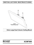
1
I n s t a l l a t i o n & U s e r ’s G u i d e
Individual / Video Wall Mount
MICRO-ADJUSTABLE PULL-OUT
FLAT PANEL MOUNTS
http://www.orionimages.com
All contents of this document may change without prior notice, and actual product appearance may differ from
that depicted herein
http://www.orionimages.com
IMPORTANT WARNINGS AND
CAUTIONS!
WARNING: A WARNING alerts you to the possibility of
serious injury or death if you do not follow the instructions.
Installation and User’s Guide
CAUTION: A CAUTION alerts you to the possibility of
damage or destruction of equipment if you do not follow the
corresponding instructions.
WARNING: Failure to read, thoroughly understand, and
follow all instructions can result in serious personal injury,
damage to equipment, or voiding of factory warranty! It is the
installer’s responsibility to make sure all components are
properly assembled and installed using the instructions
provided.
WARNING: Failure to provide adequate structural strength
for this component can result in serious personal injury or
damage to equipment! It is the installer’s responsibility to
make sure the structure to which this component is attached
can support five times the combined weight of all equipment.
Reinforce the structure as required before installing the
component. The wall to which the mount is being attached
may have a maximum drywall thickness of 5/8" (1.6cm).
WARNING: Exceeding the weight capacity can result in
serious personal injury or damage to equipment! It is the
installer’s responsibility to make sure the combined weight of
all components located on the WBLS does not exceed
150 lbs (68 kg).
7300 Bolsa Avenue, Westminster CA 92683 / Tel: 714-766-6300 / Fax: 714-766-6310
2
Installation and User’s Guide
http://www.orionimages.com
DIMENSIONS
WBLS
34.57
878.1
0
0
3.94
100
1.58
40.1
2.92
74.1
1.00
25.4
.33
8.3
.13
3.2
.62
15.7
1.11
28.2
1.60
40.7
NOTES:
1. MAXIMUM MOUNTING PATTERN WIDTH IS 30.0"[762mm].
2. MINIMUM MOUNTING PATTERN WIDTH IS 3.94"[100mm].
3. MOUNT IS 3.72"[94.4mm] DEEP WHEN FLAT TO WALL.
EXTENSION DISTANCE IS 7.0"[177.8mm] WITH A MAXIMUM
EXTENSION FROM WALL OF 10.7"[272mm].
FOR RECESSED APPLICATIONS, MINIMUM VERTICAL LIFT
3.72
94.4
2.09
53.2
2.59
65.7
3.08
78.2
3.57
90.7
4.06
103.2
4.55
115.7
5.05
128.2
16.52
419.6
5.54
140.7
6.03
153.2
15.10
383.4
DIAMOND & NOTCH ALIGN
WITH VERTICAL CL OF MOUNT
12.00" MINIMUM SPACING
WALL PLATES SLIDE FREELY ON RAILS
30.00" [762mm] MAX
3.94" [100mm] MIN
6.52
165.7
7.01
178.2
7.51
190.7
8.00
203.2
8.49
215.7
8.98
228.2
9.48
240.7
9.97
253.2
10.46
265.7
13.90
353.2
14.40
365.7
17.84
453.2
18.33
465.7
19.94
506.4
21.00
533.4
7.00
177.8
MEASUREMENTS: [MILLIMETERS]
INCHES
7300 Bolsa Avenue, Westminster CA 92683 / Tel: 714-766-6300 / Fax: 714-766-6310
3
Installation and User’s Guide
http://www.orionimages.com
LEGEND
Tighten Fastener
By Hand
Loosen Fastener
Phillips Screwdriver
Hex-Head Wrench
Remove
Adjust
Open-Ended Wrench
Pencil Mark
Drill Hole
Optional
Security Wrench
TOOLS REQUIRED FOR INSTALLATION
#2
7/32" (5.5mm) Wood Stud
5/16" (7.9mm) Concrete
M5 (included)
3/16-6" (included)
1/2"
(included)
7300 Bolsa Avenue, Westminster CA 92683 / Tel: 714-766-6300 / Fax: 714-766-6310
4
Installation and User’s Guide
http://www.orionimages.com
PARTS
A (8)
M4x16mm
B (6)
M4x20mm
D (6)
M5x16mm
E (6)
M5x20mm
G (6)
M6x16mm
H (6)
M6x25mm
I (6)
M8x20mm
L (8)
.750x.323x.250
J (6)
M8x30mm
C (6)
M4x25mm
F (6)
M5x25mm
R (1)
[wall mount]
(LSMVU shown)
K (4)
M8x50mm
N (8)
M (8)
[universal washer]
.750x.344x.500
S (2)
P (1)
[security
bracket]
M5
T (2)
[packed with ’N’]
[hold-back bracket]
QA (4)
5/16"
W (1)
3/16 -6"
QB (4)
5/16"
QC (4)
5/16" x 2-1/2"
U (1)
[left pull-out upright]
X (1)
1/2"
V (1)
[right pull-out upright]
(LSMVU uprights shown)
Y (4)
[wall bracket cap]
(LSMVU only)
7300 Bolsa Avenue, Westminster CA 92683 / Tel: 714-766-6300 / Fax: 714-766-6310
5
Installation and User’s Guide
http://www.orionimages.com
INSTALLATION
WARNING: IMPROPER INSTALLATION CAN LEAD TO
MOUNT FALLING CAUSING SEVERE PERSONAL INJURY
OR DAMAGE TO EQUIPMENT! It is the installers
responsibility to make certain the structure to which the
mount is being attached is capable of supporting five times
the weight of the WBLS and all attached equipment not to
exceed 150 lbs (68 kg).
NOTE: Proceed to either the Installing WBLS to a Wood
Stud Wall, Installing WBLS to Wall - Concrete,
Concrete Block
IMPORTANT ! : For video wall mounting, mounts should
be installed one screen height apart vertically and
approximately one screen width apart horizontally. (See
Figure 1)
Figure 2
5.
Using a level, mark the wall on each stud to attach the
mount through the upper mounting slots. (See Figure 3)
WARNING: ELECTRICAL SHOCK HAZARD! CUTTING
OR DRILLING INTO ELECTRICAL CORDS OR CABLES
CAN CAUSE DEATH OR SERIOUS PERSONAL INJURY!
ALWAYS make certain area behind mounting surface is free
of electrical wires and cables before drilling or installing
fasteners.
WARNING: EXPLOSION AND FIRE HAZARD! CUTTING
OR DRILLING INTO GAS PLUMBING CAN CAUSE DEATH
OR SERIOUS PERSONAL INJURY! ALWAYS make certain
area behind mounting surface is free of gas, water, waste, or
any other plumbing before cutting, drilling, or installing
fasteners.
Figure 1
Mounting WBLS to Wall
The WBLS has been designed to be mounted directly onto
either a wood stud or concrete wall.
Installing WBLS to a Wood Stud Wall
1.
Determine the center of the TV screen, and where it should
be located on the wall.
2.
Locate the closest stud to the left and right of the selected
location.
NOTE: If the screen area lies over a stud, use that stud and the
stud to either the left or right of it.
3.
Line up the notches on mount (R) with center of screen
marking to determine vertical center. (See Figure 2)
4.
Measure up 7-1/2" (190.5mm) from the center point to mark
location of the upper mounting slots. (See Figure 2)
Figure 3
7300 Bolsa Avenue, Westminster CA 92683 / Tel: 714-766-6300 / Fax: 714-766-6310
6
Installation and User’s Guide
http://www.orionimages.com
6.
Drill one 7/32" pilot hole in each stud.
7.
Use two 5/16 x 2-1/2" lag bolts (QC) and two 5/16" flat
washers (QB) to attach top of mount (R) to wall. (See
Figure 3)
8. Mark the attachment points for the lower mounting slots,
making sure the attachment points are located on the studs.
(See Figure 3)
9. Drill 7/32" pilot holes at markings for lower mounting holes.
(See Figure 3)
10. Use two 5/16 x 2-1/2" lag bolts (QC) and two 5/16" flat
washers (QB) to attach the mount to the wall through the
lower mounting holes. (See Figure 3)
6 10
(QA) x 4
4
8
5
9
x4
(R)
11. Slide rails to approximate center of screen location.
Installing WBLS to Wall - Concrete, Concrete
Block
1.
Determine the center of the TV screen, and where it should
be located on the wall.
2.
Line up the notches on mount (R) with center of screen
marking to determine vertical center. (See Figure 4)
3.
Measure up 7-1/2" (190.5mm) from the center point to mark
location of the upper mounting slots. (See Figure 4)
4.
Using a level, mark the wall through both upper mounting
slots. (See Figure 4)
CAUTION: MINIMUM HORIZONTAL DISTANCE
BETWEEN WALL BRACKETS IS 12" (304.8mm). Do not
place mounting brackets closer together than 12" (304.8mm).
WARNING: ELECTRICAL SHOCK HAZARD! CUTTING
OR DRILLING INTO ELECTRICAL CORDS OR CABLES
CAN CAUSE DEATH OR SERIOUS PERSONAL INJURY!
ALWAYS make certain area behind mounting surface is free
of electrical wires and cables before drilling or installing
fasteners.
7 11
(QC) x 4
(QB) x 4
Figure 4
5.
Drill one 5/16" pilot hole at each marking.
6.
Install an anchor (QA) into each upper pilot hole using a
hammer, making sure that the anchor is flush with the wall.
7.
Use two 5/16 x 2-1/2" lag bolts (QC) and two 5/16" flat
washers (QB) to attach top of mount (R) to anchors in wall.
8.
Mark the attachment points for the lower mounting slots.
(See Figure 4)
Drill one pilot hole at each marking for lower mounting
holes. (See Figure 4)
9.
10. Install an anchor (QA) into each lower pilot hole using a
hammer. (See Figure 4)
11. Use two 5/16 x 2-1/2" lag bolts (QC) and two 5/16" flat
washers (QB) to attach the mount to the wall through the
lower mounting holes. (See Figure 4)
12. Slide rails to approximate center of screen location.
WARNING: EXPLOSION AND FIRE HAZARD! CUTTING
OR DRILLING INTO GAS PLUMBING CAN CAUSE DEATH
OR SERIOUS PERSONAL INJURY! ALWAYS make certain
area behind mounting surface is free of gas, water, waste, or
any other plumbing before cutting, drilling, or installing
fasteners.
7300 Bolsa Avenue, Westminster CA 92683 / Tel: 714-766-6300 / Fax: 714-766-6310
7
Installation and User’s Guide
http://www.orionimages.com
Attaching Interface Brackets to TV
2.
1.
Align the center of the pull-out uprights (U and V) with center
of screen. (See Figure 9)
NOTE: Do NOT allow both interface brackets (U and V) to be
NOTE: The diamond-shape hole in the bracket corresponds to
NOTE: NEVER place both interface brackets (U and V) to one
the center of the mount.
Adjust Velcro® pull strap (if necessary) so it does not
extend beyond bottom of screen. (See Figure 11)
located on same side of wall bracket. (See Figure 11)
side of the wall mount center line! (See Figure 11)
Center Line (CL)
Pullstrap
Pull strap
NEVER place both interface brackets to one
side of the wall mount center line (CL)!
Center of bracket
Figure 9
WARNING: IMPROPER INSTALLATION CAN LEAD TO
DISPLAY FALLING CAUSING SERIOUS PERSONAL
INJURY OR DAMAGE TO EQUIPMENT! Using screws of
improper size may damage your display. Properly sized
screws will easily and completely thread into display
mounting holes. If spacers are required, be sure to use longer
screws of the same diameter.
2.
Select correct screws, spacers (if necessary) and universal
washers from the hardware bag (A-N) and attach brackets
(U and V) to back of screen. (See Figure 9)
NOTE: Uprights may need to be pulled out to the extended
position in order to install screws through proper holes.
Attaching Screen to Wall Mount
1.
Both interface brackets must NEVER be located
to one side of the wall brackets!
Attach wall bracket caps (Y) to top and
bottom of both wall brackets. (See Figure 10)
Figure 11
3.
4.
5.
Hang top hook of interface brackets (U and V) onto the top
bar of the mount (R). (See Figure 12)
Slide screen and bars to desired viewing position.
Route cables between wall and bars.
NOTE: The pull-out feature allows the screen to be pulled away
from the wall for easy cable access following
installation.
CAUTION: PINCH POINTS! Keep fingers, hands and
cables out of pinch point areas.
(Y) x 4
6.
Figure 10
Pull downward on the pullstraps and swing inward toward
wall, latching interface brackets to lower bar and locking
bottom of screen to the mount. (See Figure 12)
7300 Bolsa Avenue, Westminster CA 92683 / Tel: 714-766-6300 / Fax: 714-766-6310
8
Installation and User’s Guide
http://www.orionimages.com
Adjusting Roll/Height of Wall Brackets
NOTE: The height adjust wall brackets allow adjustment of + 1/2".
Top
Hook
1.
Turn to right (tighten) to raise side of screen (See Figure 14).
2.
Turn to left (loosen) to lower side of the screen.
1
Raises screen
2
3
Lowers screen
(W)
(Screen not shown for clarity)
Figure 14
Pullstraps
Locking Mount (Optional)
6
(Screen not shown for clarity)
Figure 12
Plumb Adjustment
1.
Using the provided 1/2" wrench (X), turn plumb adjustment
bolt to the left to adjust screen away from the wall. (See
Figure 13)
2.
Using the provided 1/2" wrench (X), turn plumb adjustment
bolt to the right to adjust screen toward the wall. (See
Figure 13)
1
1.
Add security bracket (S) to the mount. (See Figure 15)
2.
Add padlock (not included) through holes on small security
bracket (S) and mount.
3.
Add hold-back bracket (T) to the mount to secure mount in
recessed position. (See Figure 15)
4.
Repeat Steps 1-3 for the other upright for additional security.
3 (T)
1 (S)
2
2
1
2
Figure 13
plumb adjustment
bolt
Figure 15
7300 Bolsa Avenue, Westminster CA 92683 / Tel: 714-766-6300 / Fax: 714-766-6310
9
Installation and User’s Guide
http://www.orionimages.com
USA / Headquarter A
P
F
Europe / UK
A
7300 Bolsa Avenue, Westminster CA 92683
714-766-6300
714-766-6310
102 Knightwood Crescent, New Malden,
Surrey. KT3 5JW U.K.
P +44 (0) 7979-152-943
ORION Images, Corporation.
Design, Develop, Manufacture LCD / LED
Security Monitors
2011 ORION Images, Corp. All rights
reserved
www.orionimages.com
Asia / Korea
A 403-403, Bucheon Technopark 4 Danji Apt.,
193, Yakdae-dong, Wonmi-gu, Bucheon-si,
Gyeonggi-do 420-734, Korea
P 82-70-8240-4400
F 82-70-8240-4403