1
125, 130, 49HP AND 185 USER MANUAL
SECTION 2
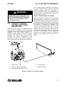
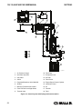
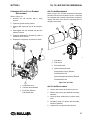
1. Fluid Cooler
4. Fluid Filter
2. Compressor
5. Receiver/Tank
3. Thermal Valve
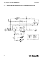
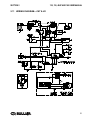
Figure 2-2: Compressor Cooling and Lubrication System
2.5
COMPRESSOR DISCHARGE
SYSTEM, FUNCTIONAL
DESCRIPTION
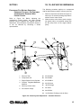
Refer to Figure 2-2. The Sullair compressor unit
discharges a compressed air/fluid mixture into the
receiver tank. The receiver tank has three functions:
1. It acts as a primary fluid separator.
2. Serves as the compressor fluid reservoir.
3. Houses the air/fluid separator.
The compressed air/fluid mixture enters the receiver
tank and is directed against the side of the sump.
Because of a change of direction and reduction of
velocity, large droplets of fluid separate and fall to the
bottom of the sump. The small amount of fluid
remaining in the compressed air collects on the
surface of the separator element as the compressed
air flows through the separator. As more fluid collects
20
on the element surface, it then flows to the bottom of
the separator. A return line (or scavenge tube) leads
from the bottom of the separator element to the inlet
region of the compressor unit. Fluid collecting on the
bottom of the separator element is returned to the
compressor by the pressure difference between the
area surrounding the separator element and the
compressor inlet. An orifice (protected by a strainer)
is included in this return line to assure proper and
unobstructed flow. The receiver tank is code rated at
200 psig (13.8 bar) working pressure. A minimum
pressure device located downstream from the
separator, ensures a minimum receiver pressure of
80 psig (5.5 bar) during all conditions. Keeping this
pressure level stable is necessary for proper air/fluid
separation and proper fluid circulation. A pressure
relief valve (located on the wet side of the separator)
is set to open if the sump pressure exceeds 200 psig
(13.8 bar).