1
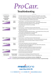
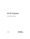
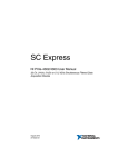
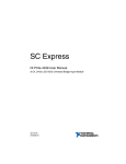
INSTALLATION GUIDE
8-Slot NI PXIe-1082 Backplane
This guide describes installation requirements for the 8-slot NI PXIe-1082
backplane.
Contents
NI PXIe-1082 Backplane Overview ....................................................... 2
Interoperability with CompactPCI................................................... 3
System Controller Slot..................................................................... 3
Hybrid Peripheral Slots.................................................................... 4
PXI Express Peripheral Slots ........................................................... 4
System Timing Slot ......................................................................... 4
PXI Local Bus.................................................................................. 6
PXI Trigger Bus............................................................................... 6
System Reference Clock .................................................................. 7
PXIe_SYNC_CTRL ........................................................................ 9
Mechanical Requirements....................................................................... 10
Mounting.......................................................................................... 10
Dimensions ...................................................................................... 11
Cooling............................................................................................. 11
Handling.................................................................................................. 12
Electrical Requirements .......................................................................... 13
PXI Connectors................................................................................ 13
Power ............................................................................................... 14
Connector J37 ........................................................................... 14
Connector J36 ........................................................................... 16
Connector J35 ........................................................................... 16
Connectors J2, J3, and J4.......................................................... 17
Backplane Specifications ................................................................. 17
System Synchronization Clock (PXI_CLK10, PXIe_CLK100,
PXIe_SYNC100) Specifications................................................... 18
10 MHz System Reference Clock: PXI_CLK10 ...................... 18
100 MHz System Reference Clock: PXIe_CLK100 and
PXIe_SYNC100 .................................................................... 18
External Clock Source .............................................................. 19
PXIe_SYNC_CTRL..................................................................19
PXI Differential Star Triggers (PXIe-DSTARA,
PXIe-DSTARB, PXIe-DSTARC) ..........................................19
Pinouts .....................................................................................................20
System Controller Slot Pinouts ........................................................21
System Timing Slot Pinouts .............................................................22
Hybrid Slot Pinouts ..........................................................................23
NI PXIe-1082 Backplane Overview
This section provides an overview of the backplane features for the
NI PXIe-1082 chassis. Figure 1 shows the backplane.
Figure 1. 8-Slot NI PXIe-1082 Backplane
8-Slot NI PXIe-1082 Backplane Installation Guide
2
ni.com
Interoperability with CompactPCI
With the NI PXIe-1082, you can use the following devices in a single
PXI Express system:
•
PXI Express-compatible products
•
CompactPCI Express-compatible 4-Link system controller products
•
CompactPCI Express-compatible Type-2 peripheral products
•
Hybrid-compatible PXI peripheral products
•
Standard CompactPCI peripheral products
Link #4
Link #3
Link #2
0
x4
Link #1
x4
0
PLX
PEX8612
PCIe Switch
5
x4
1
1
x4
x4
0
PLX
PEX8612
PCIe Switch
x4
5
PLX
PEX8616
PCIe Switch
1
5
x4
x4
6
x4
x4
PCIe/PCI
Bridge
H
1
2
3
4
5
H
6
H
7
H
8
Figure 2. NI PXIe-1082 Backplane Architecture
System Controller Slot
The system controller slot is Slot 1 of the chassis and is a 4-Link
configuration system slot as defined by the CompactPCI Express and
PXI Express specifications. It has three system controller expansion slots
for system controller modules that are wider than one slot. These slots
allow the system controller to expand to the left to prevent the system
controller from using peripheral slots.
The backplane routes the first x4 PCI Express link from the system slot
directly to slot 2. The other three x4 PCI Express links each are routed
from the system slot to a PCI Express switch. The three PCI Express
switches have x4 PCI Express links routed to each remaining peripheral
© National Instruments
3
8-Slot NI PXIe-1082 Backplane Installation Guide
slot. One PCI Express switch also has a x1 PCI Express link routed to a
PCI Express-to-PCI bridge that provides a 32-bit, 33 MHz PCI bus to the
four hybrid slots. Refer to Figure 2 for the connectivity of PCI Express
and PCI.
By default, the system controller controls the power supply with the
PS_ON# signals. A logic low on this line turns on the power supply.
Hybrid Peripheral Slots
The backplane includes four hybrid peripheral slots as defined by the PXI-5
PXI Express Hardware Specification: slots 5 to 8. A hybrid peripheral slot
can accept the following peripheral modules:
•
A PXI Express peripheral with a x4 or x1 PCI Express link to the
system slot or through a switch to the system slot.
•
A CompactPCI Express Type-2 peripheral with a x4 or x1 PCI Express
link to the system slot or through a switch to the system slot.
•
A hybrid-compatible PXI peripheral module modified by replacing the
J2 connector with an XJ4 connector installed in the upper eight rows
of J2. Refer to the PXI Express Specification for details. The PXI
peripheral communicates through the backplane 32-bit PCI bus.
•
A CompactPCI 32-bit peripheral on the backplane 32-bit PCI bus.
The hybrid peripheral slots provide full PXI Express functionality and
32-bit PXI functionality except for PXI Local Bus. The hybrid peripheral
slot connects only to PXI Local Bus 6 left and right.
PXI Express Peripheral Slots
There are two PXI Express peripheral slots: slots 2 and 3. PXI Express
peripheral slots can accept the following modules:
•
A PXI Express peripheral with a x4 or x1 PCI Express link to the
system slot or through a switch to the system slot.
•
A CompactPCI Express Type-2 peripheral with a x4 or x1 PCI Express
link to the system slot or through a switch to the system slot.
System Timing Slot
The system timing slot is slot 4. The system timing slot accepts the
following peripheral modules:
•
A PXI Express system timing module with a x4 or x1 PCI Express link
to the system slot through a PCI Express switch.
•
A PXI Express peripheral with a x4 or x1 PCI Express link to the
system slot through a PCI Express switch.
•
A CompactPCI Express Type-2 peripheral with a x4 or x1 PCI Express
link to the system slot through a PCI Express switch.
8-Slot NI PXIe-1082 Backplane Installation Guide
4
ni.com
The system timing slot has three dedicated differential pairs
(PXIe_DSTAR) connected from the TP2 connector to the XP3 connector
for each PXI Express peripheral or hybrid peripheral slot, as well as routed
back to the XP3 connector of the system timing slot, as shown in Figure 3.
You can use the PXIe_DSTAR pairs for high-speed triggering,
synchronization, and clocking. Refer to the PXI Express Specification
for details.
The system timing slot also has a single-ended (PXI Star) trigger connected
to every slot. Refer to Figure 3 for details.
The system timing slot has a pin (PXI_CLK10_IN) through which a system
timing module can source a 10 MHz clock to which the backplane
phase-locks. Refer to the System Reference Clock section for details.
The system timing slot has a pin (PXIe_SYNC_CTRL) through which a
system timing module can control the PXIe_SYNC100 timing. Refer to the
PXI Express Specification and the PXIe_SYNC_CTRL section for details.
PXI_STAR2
PXI_STAR6
PXI_STAR5
PXI_STAR0
PXI_STAR4
2
3
4
5
H
6
PXIe_DSTAR11
PXIe_DSTAR9
PXIe_DSTAR8
H
1
PXIe_DSTAR10
PXI_STAR3
PXIe_DSTAR0
PXIe_DSTAR1
PXIe_DSTAR1
PXIe_DSTAR2
PXI_STAR1
H
7
H
8
Figure 3. PXIe_DSTAR and PXI Star Connectivity Diagram
© National Instruments
5
8-Slot NI PXIe-1082 Backplane Installation Guide
PXI Local Bus
The PXI backplane local bus is a daisy-chained bus that connects each
peripheral slot with adjacent peripheral slots to the left and right.
The backplane routes PXI Local Bus 6 between adjacent PXI slots. The left
local bus 6 from slot 1 is not routed anywhere, and the right local bus signal
from slot 18 is not routed anywhere.
Local bus signals may range from high-speed TTL signals to analog signals
as high as 42 V.
Initialization software uses the configuration information specific to each
adjacent peripheral module to evaluate local bus compatibility.
PXI Trigger Bus
All slots on the same PXI bus segment share eight PXI trigger lines. You
can use these trigger lines in a variety of ways. For example, you can use
triggers to synchronize the operation of several different PXI peripheral
modules. In other applications, one module in the system timing slot can
control carefully timed sequences of operations performed on other
modules in the system. Modules can pass triggers to one another, allowing
precisely timed responses to asynchronous external events the system is
monitoring or controlling. Figure 4 shows the PXI trigger bus connectivity.
PXI Trigger Bus
H
1
2
3
4
5
H
6
H
7
H
8
Figure 4. PXI Trigger Bus Connectivity Diagram
8-Slot NI PXIe-1082 Backplane Installation Guide
6
ni.com
System Reference Clock
The NI PXIe-1082 chassis supplies PXI_CLK10, PXIe_CLK100, and
PXIe_SYNC100 to every peripheral slot with an independent driver for
each signal.
An independent buffer (having a source impedance matched to the
backplane and a skew of less than 500 ps between slots) drives PXI_CLK10
to each peripheral slot. You can use this common reference clock signal to
synchronize multiple modules in a measurement or control system.
An independent buffer drives PXIe_CLK100 to each peripheral slot. These
clocks are matched in skew to less than 100 ps. The differential pair must
be terminated on the peripheral with LVPECL termination for the buffer to
drive PXIe_CLK100 so that when there is no peripheral or a peripheral that
does not connect to PXIe_CLK100, no clock is being driven on the pair to
that slot. Refer to Figure 5 for a termination example.
CLK100 +
+
CLK100 –
–
50 Ω
50 Ω
47 Ω
0.01 μF
Figure 5. CLK100 Termination
An independent buffer drives PXIe_SYNC100 to each peripheral slot. The
differential pair must be terminated on the peripheral with LVPECL
termination for the buffer to drive PXIe_SYNC100 so that when there is
no peripheral or a peripheral that does not connect to PXIe_SYNC100, no
SYNC100 signal is being driven on the pair to that slot. Refer to Figure 5
for a termination example.
In summary, PXI_CLK10 is driven to every slot. PXIE_CLK100 and
PXIE_SYNC100 are driven to every peripheral slot.
© National Instruments
7
8-Slot NI PXIe-1082 Backplane Installation Guide
PXI_CLK10, PXIe_CLK100, and PXIe_SYNC100 have the default timing
relationship described in Figure 6.
0 1 2 3 4 5 6 7 8 9 0 1 2 3 4 5 6 7 8 9 0 1 2 3 4 5 6 7 8 9
PXIe_CLK100
PXI_CLK10
PXIe_SYNC100
Figure 6. System Reference Clock Default Behavior
To synchronize the system to an external clock, you can drive PXI_CLK10
from an external source through the PXI_CLK10_IN pin on the System
Timing Slot. Refer to Table 10, XP4 Connector Pinout for the System
Timing Slot, for the pinout. When a 10 MHz clock is detected on this pin,
the backplane automatically phase-locks the PXI_CLK10, PXIe_CLK100,
and PXIe_SYNC100 signals to this external clock and distributes these
signals to the slots. Refer to the Backplane Specifications section for the
specification information for an external clock provided on the
PXI_CLK10_IN pin of the system timing slot.
You also can drive a 10 MHz clock on connector J36. Refer to Figure 11 for
the location of this connector. When a 10 MHz clock is detected on this
connector, the backplane automatically phase-locks the PXI_CLK10,
PXIe_CLK100, and PXIe_SYNC100 signals to this external clock and
distributes these signals to the slots. Refer to the Backplane Specifications
section for the specification information for an external clock provided
on J36.
If the 10 MHz clock is present on both the PXI_CLK10_IN pin of the
System Timing Slot and connector J36, the signal on the System Timing
Slot is selected. Refer to Table 1, which explains how the backplane selects
the 10 MHz clocks.
8-Slot NI PXIe-1082 Backplane Installation Guide
8
ni.com
Table 1. Backplane External Clock Input Truth Table
System Timing Slot
PXI_CLK10_IN
J36 10 MHz REF IN
Backplane PXI_CLK10,
PXIe_CLK100 and PXIe_SYNC100
No clock present
No clock present
Backplane generates its own clocks
No clock present
10 MHz clock present
PXI_CLK10, PXIe_CLK100 and
PXIe_SYNC100 all phase-locked to
J36—10 MHz REF IN
10 MHz clock present
No clock present
PXI_CLK10, PXIe_CLK100 and
PXIe_SYNC100 all phase-locked to
System Timing Slot—PXI_CLK10_IN
10 MHz clock present
10 MHz clock present
PXI_CLK10, PXIe_CLK100 and
PXIe_SYNC100 all phase-locked to
System Timing Slot—PXI_CLK10_IN
A copy of the backplane’s PXI_CLK10 is exported to connector J36. Refer
to Figure 11 for the location of this connector. An independent buffer drives
this clock. Refer to the Backplane Specifications section for the
specification information for the 10 MHz REF OUT signal on J36.
PXIe_SYNC_CTRL
PXIe_SYNC100 is by default a 10 ns pulse synchronous to PXI_CLK10.
The frequency of PXIe_SYNC100 is 10/n MHz, where n is a positive
integer. The default for n is 1, giving PXIe_SYNC100 a 100 ns period.
However, the backplane allows n to be programmed to other integers. For
example, setting n = 3 creates a PXIe_SYNC100 with a 300 ns period while
still maintaining its phase relationship to PXI_CLK10. The n value can be
any positive integer from 1 to 255.
The system timing slot has a control pin for PXIe_SYNC100 called
PXIe_SYNC_CTRL, for use when n > 1. Refer to Table 9, XP3 Connector
Pinout for the System Timing Slot, for the system timing slot pinout. Refer
to the Backplane Specifications section for the PXIe_SYNC_CTRL input
specifications.
By default, a high level detected by the backplane on the
PXIe_SYNC_CTRL pin causes a synchronous restart for the
PXIe_SYNC100 signal. On the next PXI_CLK10 edge, the
PXIe_SYNC100 signal restarts. This allows several chassis to have
their PXIe_SYNC100 in phase with each other. Refer to Figure 7 for
timing details with this method.
© National Instruments
9
8-Slot NI PXIe-1082 Backplane Installation Guide
PXI_CLK10
PXIe_SYNC_CTRL
PXIe_SYNC100
SYNC100 Divider
Restarted Here
Figure 7. PXIe_SYNC100 at 3.33 MHz Using PXIe_SYNC_CTRL as Restart
Mechanical Requirements
Mounting
Figure 8 shows the backplane dimensions. There are 22 holes available for
mounting with M2.5 hardware.
Use all mounting holes for proper backplane support.
Eight mounting holes on top of the backplane have plated annular pads on
the back of the backplane. Use these mounting holes to connect the
backplane ground to the chassis in which the backplane is mounted. If you
do not want to connect the backplane ground to the chassis, use insulated
washers at these mounting holes. Refer to Figure 11 for the mounting hole
positions.
8-Slot NI PXIe-1082 Backplane Installation Guide
10
ni.com
Dimensions
0.89 in.
(22.61 mm)
0.125 in.
(3.18 mm)
0.375 in.
(9.53 mm)
5.933 in.
(150.70 mm)
0.122 in.
(3.10 mm)
0.824 in.
(20.92 mm)
0.800 in.
(20.32 mm)
9.843 in.
(250 mm)
Figure 8. Dimensions
Cooling
National Instruments is not responsible for damage to the backplane if inadequate
cooling is used.
Note
Airflow should be from the bottom to the top of the PXI modules. You must
determine the airflow requirements for your system based on the PXI
Hardware Specification.
The backplane must be adequately cooled to function reliably. Ensure that
the components shown in Figure 9 are kept below their maximum case
temperatures throughout the operating range.
© National Instruments
11
8-Slot NI PXIe-1082 Backplane Installation Guide
2
1
9
8
7
1
2
3
4
5
5
6
U7—125.00 °C
U12—125.00 °C
U36—113.29 °C
U46—113.29 °C
U33—123.95 °C
4
3
6
7
8
9
U47—123.95 °C
U42—124.40 °C
U34—123.95 °C
U31—112.49 °C
Figure 9. Thermally Relevant Component Recommended Maximum
Operating Case Temperature (°C)
Handling
Be careful to avoid bending or otherwise damaging the pins on the backplane
connectors. Bent pins may cause functional failures or damage when the backplane is
powered.
Caution
To protect both yourself and the backplane from electrical hazards, leave the
chassis powered off until you finish installing the PXI controller and modules.
Caution
Electrostatic discharge can damage your equipment. To avoid such damage,
discharge the static built up on your body by touching a grounded metal object before
handling the PXI equipment. Then touch the antistatic plastic package containing the
backplane to a metal part of your PXI chassis before removing the backplane from the
packaging.
Caution
8-Slot NI PXIe-1082 Backplane Installation Guide
12
ni.com
Electrical Requirements
PXI Connectors
The PXI and PXI Express connectors have pin descriptions defined in the
PXI Hardware Specification and PXI Express Hardware Specification.
Figure 10 shows the connectors.
1
3
2
4
1
1
5
6
1
2
3
Card-Cage Thermistor Connectors (x3)
Slot 1 (Controller Slot)
PXI Express Peripheral Slots (2 to 3)
4
5
6
System Timing Slot (4)
Hybrid Peripheral Slots (5 to 8)
Power Button Connector
Figure 10. PXI Connectors
1
2
1
Connector J36
2
Connector J37
Figure 11. Backplane Power and J36 Connectors
© National Instruments
13
8-Slot NI PXIe-1082 Backplane Installation Guide
Power
Refer to the PXI Express Hardware Specification for power requirements
and to the specifications of the chosen power supply to determine the
minimum load required.
Connector J37
Connector J37 is the NI PXIe-1082 backplane power supply connector.
Figure 11 shows the J37 location. Refer to Table 2 for the pin descriptions.
Connector J37 consists of eight #12 pins (1 to 4 and 26 to 29) for power.
There also are 21 #20 pins (5 to 25) for mixed power and signaling. Table 2
also indicates which pins must be connected for basic backplane operation.
Refer to the CompactPCI Express specification for details regarding
PS_ON# and PS_OK.
Do not use the voltage sense pins (22, 23, and 25) to power the board. These pins
are connected by thin trace to the backplane center and are for voltage sensing only.
Providing current through these pins may damage the backplane. If your power supply has
voltage sensing, use these pins; otherwise, leave them unconnected. Pins with “power
plane” in the description are connected to the backplane’s internal power planes and are
suitable for carrying current.
Caution
Note Tyco Electronics manufactures the J37 mating connector, which you can order with
part number 298-08-01100.
The connector SMBus pins are connected to the backplane SMBus, which the
CompactPCI Express specification defines. (The specification also defines uses and
addressing.) Improper use of the SMBus could result in system controller malfunctions.
Note
There are three SMBus slave devices on the NI PXIe-1082 backplane. The
Backplane Descriptor EEPROM is at slave address A4H as defined by the
CompactPCI Express specification, and the backplane clocking CPLD is at
slave address 5AH. There is a temperature monitoring device at slave
address 5CH. If you must connect an SMBus slave device to the J37 SMBus
pins, use slave address 58H.
8-Slot NI PXIe-1082 Backplane Installation Guide
14
ni.com
Table 2. Connector J37 Pin Descriptions
Connector
© National Instruments
Pin
Signal
Description
Required
for Basic
Power Up
1
+3.3V
+3.3 V power plane
Yes
2
GND
Ground plane
Yes
3
+3.3V
+3.3 V power plane
Yes
4
GND
Ground plane
Yes
5
5VAUX
5VAUX power plane
Yes
6
GND
Ground plane
Yes
7
-12V
-12 V power plane
Yes
8
GND
Ground plane
Yes
9
SMBCLK
Backplane SMBus clock
No
10
SMBDAT
Backplane SMBus data
No
11
SMBALERT#
Backplane SMBus alert#
No
12
PS_ON#
From system
slot J18—pin D2
No
13
PS_OK
To system slot from
power supply
Yes
14
LED1
J35—pin 3
No
15
LED2
J35—pin 4
No
16
GND
Ground plane
Yes
17
-12V
-12 V power plane
Yes
18
GND
Ground plane
Yes
19
OVERTEMP#
Alert of over-temperature
condition in card cage
No
20
12V_FAN
To pin 7 of test header W1
No
21
GND
Ground plane
Yes
22
+12V_SENSE
+12 V sense only, no power
No
23
+3.3V_SENSE
+3.3 V sense only,
no power
No
24
GND
Ground plane
Yes
25
+5V_SENSE
+5 V sense only, no power
No
26
+12V
+12 V power plane
Yes
27
GND
Ground plane
Yes
15
8-Slot NI PXIe-1082 Backplane Installation Guide
Table 2. Connector J37 Pin Descriptions (Continued)
Connector
Pin
Signal
Description
Required
for Basic
Power Up
28
+5V
+5 V power plane
Yes
29
GND
Ground plane
Yes
Connector J36
Connector J36 is for interfacing with the backplane PXI_CLK10
circuitry. Figure 11 shows the J36 connector location. Positronic
manufactures the J36 mating connector, which you can order with
part number CBD7W2M2000Z-759.1.
Ground
Cable Shield
10 MHz
OUT
Cable Shield
10 MHz
IN
Figure 12. J36 Connector
Connector J35
Use connector J35 in conjunction with J37 for interfacing with an inhibit
switch and LED. You do not need to connect anything to J35 for basic
backplane power up. Refer to Table 3 for the pin descriptions. The power
button (PWRBTN#) signal is a momentary pushbutton signal that tells the
system controller to enable or inhibit the power supply. You can use signals
LED1 and LED2 to drive a bicolor LED in the power switch, but you also
can use these signals to carry another digital signal.
8-Slot NI PXIe-1082 Backplane Installation Guide
16
ni.com
Table 3. Connector J35 Pin Descriptions
Connector
J35
Pin
Signal
Description
1
PWRBTN#
Input to system
slot J18—pin F2
2
GND
Ground plane
3
LED1
J37—pin 14
4
LED2
J37—pin 15
4
3
2
1
Connectors J2, J3, and J4
Use these connectors for three thermistors to monitor the card-cage
temperature. You can use signal OVERTEMP# on J37 as an alarm
indicating when the card-cage temperature exceeds 90 °C when used in
conjunction with the four thermistors.
Note
Use a Sensor Scientific KWM502C-6 or similar thermistor with these connectors.
Note
The mating connector for J2, J3, and J4 is Molex part number 50-57-9402.
Backplane Specifications
Size......................................................... 3U-sized; one system slot
(with three system expansion
slots) and 7 peripheral slots.
Compliant with IEEE 1101.10
mechanical packaging.
PXI Express specification
compliant.
Accepts both PXI Express and
CompactPCI (PICMG 2.0 R 3.0)
3U modules.
Backplane bare-board material .............. UL 94 V-0 Recognized
Backplane connectors ............................ Conforms to IEC 917 and
IEC 1076-4-101, and are
UL 94 V-0 rated
© National Instruments
17
8-Slot NI PXIe-1082 Backplane Installation Guide
System Synchronization Clock (PXI_CLK10, PXIe_CLK100,
PXIe_SYNC100) Specifications
10 MHz System Reference Clock: PXI_CLK10
Maximum slot-to-slot skew ....................500 ps
Accuracy .................................................±25 ppm max (guaranteed over
the operating temperature range)
Maximum jitter .......................................5 ps RMS phase-jitter (10 Hz to
1 MHz range)
Duty-factor..............................................45% to 55%
Unloaded signal swing............................3.3 V ±0.3 V
Note
For other specifications, refer to the PXI-1 Hardware Specification.
100 MHz System Reference Clock: PXIe_CLK100 and
PXIe_SYNC100
Maximum slot-to-slot skew ....................100 ps
Accuracy .................................................±25 ppm max (guaranteed over
the operating temperature range)
Maximum jitter .......................................3 ps RMS phase-jitter (10 Hz to
12 kHz range)
2 ps RMS phase-jitter (12 kHz to
20 MHz range)
Duty-factor for PXIe_CLK100...............45% to 55%
Absolute single-ended voltage swing
(When each line in the differential pair
has 50 Ω termination to 1.30 V
or Thévenin equivalent)..........................400 to 1000 mV
Note
For other specifications, refer to the PXI-5 PXI Express Hardware Specification.
External 10 MHz Reference Out (on J36)
Accuracy .................................................±25 ppm max (guaranteed over
the operating temperature range)
Maximum jitter .......................................5 ps RMS phase-jitter (10 Hz to
1 MHz range)
8-Slot NI PXIe-1082 Backplane Installation Guide
18
ni.com
Output amplitude.................................... 1 VPP ±20% square-wave
into 50 Ω
2 VPP unloaded
Output impedance .................................. 50 Ω ± 5 Ω
External Clock Source
Frequency............................................... 10 MHz ±100 PPM
Input amplitude
J36 ................................................... 200 mVPP to 5 VPP square-wave
or sine-wave
System timing slot
PXI_CLK10_IN.............................. 5 V or 3.3 V TTL signal
J36 input impedance............................... 50 Ω ± 5 Ω
Maximum jitter introduced
by backplane .......................................... 1 ps RMS phase-jitter (10 Hz to
1 MHz range)
PXIe_SYNC_CTRL
VIH .......................................................... 2.0 to 5.5 V
VIL .......................................................... 0 to 0.8 V
PXI Star Trigger
Maximum slot-to-slot skew ................... 250 ps
Backplane characteristic impedance ...... 65 Ω ±10%
For PXI slot to PXI Star mapping, refer to the System Timing Slot section of
Chapter 1, Getting Started, in the NI PXIe-1082 User Manual.
Note
Note
For other specifications, refer to the PXI-1 Hardware Specification.
PXI Differential Star Triggers (PXIe-DSTARA,
PXIe-DSTARB, PXIe-DSTARC)
Maximum slot-to-slot skew ................... 150 ps
Maximum differential skew ................... 25 ps
Backplane differential impedance.......... 100 Ω ±10%
© National Instruments
19
8-Slot NI PXIe-1082 Backplane Installation Guide
Note For PXI Express slot to PXI_DSTAR mapping, refer to the System Timing Slot
section of Chapter 1, Getting Started, in the NI PXIe-1082 User Manual.
For other specifications, the NI PXIe-1082 complies with the PXI-5 PXI Express
Hardware Specification.
Note
Pinouts
This section describes the connector pinouts for the NI PXIe-1082 chassis
backplane.
Table 4 shows the XP1 connector pinout for the System Controller slot.
Table 5 shows the XP2 Connector Pinout for the System Controller slot.
Table 6 shows the XP3 Connector Pinout for the System Controller slot.
Table 7 shows the XP4 Connector Pinout for the System Controller slot.
Table 8 shows the TP2 Connector Pinout for the System Timing slot.
Table 9 shows the XP3 Connector Pinout for the System Timing slot.
Table 10 shows the XP4 Connector Pinout for the System Timing slot.
Table 11 shows the P1 connector pinout for the Hybrid peripheral slots.
Table 12 shows the XP3 Connector Pinout for the Hybrid peripheral slots.
Table 13 shows the XP4 Connector Pinout for the Hybrid peripheral slots.
For more detailed information, refer to the PXI-5 PXI Express Hardware
Specification, Revision 2.0. Contact the PXI Systems Alliance for a copy
of the specification.
8-Slot NI PXIe-1082 Backplane Installation Guide
20
ni.com
System Controller Slot Pinouts
Table 4. XP1 Connector Pinout for the System Controller Slot
Pins
Signals
A
GND
B
3.3V
C
5V
D
GND
E
12V
F
12V
G
GND
Table 5. XP2 Connector Pinout for the System Controller Slot
Pin
A
B
ab
C
D
cd
E
F
ef
1
3PETp1
3PETn1
GND
3PERp1
3PERn1
GND
3PETp2
3PETn2
GND
2
3PETp3
3PETn3
GND
3PERp3
3PERn3
GND
3PERp2
3PERn2
GND
3
4PETp0
4PETn0
GND
4PERp0
4PERn0
GND
4PETp1
4PETn1
GND
4
4PETp2
4PETn2
GND
4PERp2
4PERn2
GND
4PERp1
4PERn1
GND
5
4PETp3
4PETn3
GND
4PERp3
4PERn3
GND
RSV
RSV
GND
6
RSV
RSV
GND
RSV
RSV
GND
RSV
RSV
GND
7
RSV
RSV
GND
RSV
RSV
GND
RSV
RSV
GND
8
RSV
RSV
GND
RSV
RSV
GND
RSV
RSV
GND
9
RSV
RSV
GND
RSV
RSV
GND
RSV
RSV
GND
10
RSV
RSV
GND
RSV
RSV
GND
RSV
RSV
GND
Table 6. XP3 Connector Pinout for the System Controller Slot
Pin
A
B
ab
C
D
cd
E
F
ef
1
RSV
RSV
GND
RSV
RSV
GND
RSV
RSV
GND
2
RSV
RSV
GND
PWR_OK
PS_ON#
GND
LINKCAP
PWRBTN#
GND
3
SMBDAT
SMBCLK
GND
4RefClk+
4RefClk-
GND
2RefClk+
2RefClk-
GND
4
RSV
PERST#
GND
3RefClk+
3RefClk-
GND
1RefClk+
1RefClk-
GND
© National Instruments
21
8-Slot NI PXIe-1082 Backplane Installation Guide
Table 6. XP3 Connector Pinout for the System Controller Slot (Continued)
Pin
A
B
ab
C
D
cd
E
F
ef
5
1PETp0
1PETn0
GND
1PERp0
1PERn0
GND
1PETp1
1PETn1
GND
6
1PETp2
1PETn2
GND
1PERp2
1PERn2
GND
1PERp1
1PERn1
GND
7
1PETp3
1PETn3
GND
1PERp3
1PERn3
GND
2PETp0
2PETn0
GND
8
2PETp1
2PETn1
GND
2PERp1
2PERn1
GND
2PERp0
2PERn0
GND
9
2PETp2
2PETn2
GND
2PERp2
2PERn2
GND
2PETp3
2PETn3
GND
10
3PETp0
3PETn0
GND
3PERp0
3PERn0
GND
2PERp3
2PERn3
GND
Table 7. XP4 Connector Pinout for the System Controller Slot
Pin
Z
A
B
C
D
E
F
1
GND
GA4
GA3
GA2
GA1
GA0
GND
2
GND
5Vaux
GND
SYSEN#
WAKE#
ALERT#
GND
3
GND
RSV
RSV
RSV
RSV
RSV
GND
4
GND
RSV
RSV
RSV
RSV
RSV
GND
5
GND
PXI_TRIG3
PXI_TRIG4
PXI_TRIG5
GND
PXI_TRIG6
GND
6
GND
PXI_TRIG2
GND
RSV
PXI_STAR
PXI_CLK10
GND
7
GND
PXI_TRIG1
PXI_TRIG0
RSV
GND
PXI_TRIG7
GND
8
GND
RSV
GND
RSV
RSV
PXI_LBR6
GND
System Timing Slot Pinouts
Table 8. TP2 Connector Pinout for the System Timing Slot
A
B
C
D
1
Pin
PXIe_DSTARC0+
PXIe_DSTARC0-
GND
ab
PXIe_DSTARC8+
PXIe_DSTARC8-
GND
PXIe_DSTARB8+
PXIe_DSTARB8-
GND
2
PXIe_DSTARA0+
PXIe_DSTARA0-
GND
PXIe_DSTARC9+
PXIe_DSTARC9-
GND
PXIe_DSTARA8+
PXIe_DSTARA8-
GND
3
PXIe_DSTARB0+
PXIe_DSTARB0-
GND
PXIe_DSTARC1+
PXIe_DSTARC1-
GND
PXIe_DSTARA9+
PXIe_DSTARA9-
GND
4
PXIe_DSTARB1+
PXIe_DSTARB1-
GND
PXI_STAR0
PXI_STAR1
GND
PXIe_DSTARB9+
PXIe_DSTARB9-
GND
5
PXIe_DSTARA1+
PXIe_DSTARA1-
GND
PXI_STAR2
PXI_STAR3
GND
PXIe_DSTARC10+
PXIe_DSTARC10-
GND
6
PXIe_DSTARC2+
PXIe_DSTARC2-
GND
PXI_STAR4
PXI_STAR5
GND
PXIe_DSTARA10+
PXIe_DSTARA10-
GND
7
PXIe_DSTARB2+
PXIe_DSTARB2-
GND
PXI_STAR6
NC
GND
PXIe_DSTARB10+
PXIe_DSTARB10-
GND
8
PXIe_DSTARA2+
PXIe_DSTARA2-
GND
NC
NC
GND
PXIe_DSTARC11+
PXIe_DSTARC11-
GND
9
NC
NC
GND
NC
NC
GND
PXIe_DSTARA11+
PXIe_DSTARA11-
GND
10
NC
NC
GND
NC
NC
GND
PXIe_DSTARB11+
PXIe_DSTARB11-
GND
8-Slot NI PXIe-1082 Backplane Installation Guide
22
cd
E
F
ef
ni.com
Table 9. XP3 Connector Pinout for the System Timing Slot
Pin
A
B
ab
C
D
cd
E
F
ef
1
PXIe_CLK100+
PXIe_CLK100-
GND
PXIe_SYNC100+
PXIe_SYNC100-
GND
PXIe_DSTARC+
PXIe_DSTARC-
GND
2
PRSNT#
PWREN#
GND
PXIe_DSTARB+
PXIe_DSTARB-
GND
PXIe_DSTARA+
PXIe_DSTARA-
GND
3
SMBDAT
SMBCLK
GND
RSV
RSV
GND
RSV
RSV
GND
4
MPWRGD*
PERST#
GND
RSV
RSV
GND
1RefClk+
1RefClk-
GND
5
1PETp0
1PETn0
GND
1PERp0
1PERn0
GND
1PETp1
1PETn1
GND
6
1PETp2
1PETn2
GND
1PERp2
1PERn2
GND
1PERp1
1PERn1
GND
7
1PETp3
1PETn3
GND
1PERp3
1PERn3
GND
1PETp4
1PETn4
GND
8
1PETp5
1PETn5
GND
1PERp5
1PERn5
GND
1PERp4
1PERn4
GND
9
1PETp6
1PETn6
GND
1PERp6
1PERn6
GND
1PETp7
1PETn7
GND
10
RSV
RSV
GND
RSV
RSV
GND
1PERp7
1PERn7
GND
Table 10. XP4 Connector Pinout for the System Timing Slot
Pin
Z
A
B
C
D
E
F
1
GND
GA4
GA3
GA2
GA1
GA0
GND
2
GND
5Vaux
GND
SYSEN#
WAKE#
ALERT#
GND
3
GND
12V
12V
GND
GND
GND
GND
4
GND
GND
GND
3.3V
3.3V
3.3V
GND
5
GND
PXI_TRIG3
PXI_TRIG4
PXI_TRIG5
GND
PXI_TRIG6
GND
6
GND
PXI_TRIG2
GND
ATNLED
PXI_CLK10_IN
PXI_CLK10
GND
7
GND
PXI_TRIG1
PXI_TRIG0
ATNSW#
GND
PXI_TRIG7
GND
8
GND
PXIe_SYNC_CTRL
GND
RSV
PXI_LBL6
PXI_LBR6
GND
Hybrid Slot Pinouts
Table 11. P1 Connector Pinout for the Hybrid Slot
Pin
Z
A
B
C
D
E
F
25
GND
5V
REQ64#
ENUM#
3.3V
5V
GND
24
GND
AD[1]
5V
V(I/O)
AD[0]
ACK64#
GND
23
GND
3.3V
AD[4]
AD[3]
5V
AD[2]
GND
22
GND
AD[7]
GND
3.3V
AD[6]
AD[5]
GND
21
GND
3.3V
AD[9]
AD[8]
M66EN
C/BE[0]#
GND
20
GND
AD[12]
GND
V(I/O)
AD[11]
AD[10]
GND
19
GND
3.3V
AD[15]
AD[14]
GND
AD[13]
GND
© National Instruments
23
8-Slot NI PXIe-1082 Backplane Installation Guide
Table 11. P1 Connector Pinout for the Hybrid Slot (Continued)
Pin
Z
A
B
C
D
E
F
18
GND
SERR#
GND
3.3V
PAR
C/BE[1]#
GND
17
GND
3.3V
IPMB_SCL
IPMB_SDA
GND
PERR#
GND
16
GND
DEVSEL#
GND
V(I/O)
STOP#
LOCK#
GND
15
GND
3.3V
FRAME#
IRDY#
BD_SEL#
TRDY#
GND
12 to
14
Key Area
11
GND
AD[18]
AD[17]
AD[16]
GND
C/BE[2]#
GND
10
GND
AD[21]
GND
3.3V
AD[20]
AD[19]
GND
9
GND
C/BE[3]#
IDSEL
AD[23]
GND
AD[22]
GND
8
GND
AD[26]
GND
V(I/O)
AD[25]
AD[24]
GND
7
GND
AD[30]
AD[29]
AD[28]
GND
AD[27]
GND
6
GND
REQ#
GND
3.3V
CLK
AD[31]
GND
5
GND
BRSVP1A5
BRSVP1B5
RST#
GND
GNT#
GND
4
GND
IPMB_PWR
HEALTHY#
V(I/O)
INTP
INTS
GND
3
GND
INTA#
INTB#
INTC#
5V
INTD#
GND
2
GND
TCK
5V
TMS
TDO
TDI
GND
1
GND
5V
-12V
TRST#
+12V
5V
GND
Table 12. XP3 Connector Pinout for the Hybrid Slot
Pin
A
B
ab
C
D
cd
1
PXIe_CLK100+
PXIe_CLK100-
GND
PXIe_SYNC100+
PXIe_SYNC100-
GND
2
PRSNT#
PWREN#
GND
PXIe_DSTARB+
PXIe_DSTARB-
GND
3
SMBDAT
SMBCLK
GND
RSV
RSV
GND
4
MPWRGD*
PERST#
GND
RSV
RSV
GND
5
1PETp0
1PETn0
GND
1PERp0
1PERn0
GND
6
1PETp2
1PETn2
GND
1PERp2
1PERn2
GND
7
1PETp3
1PETn3
GND
1PERp3
1PERn3
GND
8
1PETp5
1PETn5
GND
1PERp5
1PERn5
GND
9
1PETp6
1PETn6
GND
1PERp6
1PERn6
GND
10
RSV
RSV
GND
RSV
RSV
GND
8-Slot NI PXIe-1082 Backplane Installation Guide
24
E
F
ef
PXIe_DSTARC+
PXIe_DSTARC-
GND
PXIe_DSTARA+
PXIe_DSTARA-
GND
RSV
RSV
GND
1RefClk+
1RefClk-
GND
1PETp1
1PETn1
GND
1PERp1
1PERn1
GND
1PETp4
1PETn4
GND
1PERp4
1PERn4
GND
1PETp7
1PETn7
GND
1PERp7
1PERn7
GND
ni.com
Table 13. XP4 Connector Pinout for the Hybrid Slot
Pin
Z
A
B
C
D
E
F
1
GND
GA4
GA3
GA2
GA1
GA0
GND
2
GND
5Vaux
GND
SYSEN#
WAKE#
ALERT#
GND
3
GND
12V
12V
GND
GND
GND
GND
4
GND
GND
GND
3.3V
3.3V
3.3V
GND
5
GND
PXI_TRIG3
PXI_TRIG4
PXI_TRIG5
GND
PXI_TRIG6
GND
6
GND
PXI_TRIG2
GND
ATNLED
PXI_STAR
PXI_CLK10
GND
7
GND
PXI_TRIG1
PXI_TRIG0
ATNSW#
GND
PXI_TRIG7
GND
8
GND
RSV
GND
RSV
PXI_LBL6
PXI_LBR6
GND
© National Instruments
25
8-Slot NI PXIe-1082 Backplane Installation Guide
Refer to the NI Trademarks and Logo Guidelines at ni.com/trademarks for more information on
National Instruments trademarks. Other product and company names mentioned herein are trademarks
or trade names of their respective companies. For patents covering National Instruments products/
technology, refer to the appropriate location: Help»Patents in your software, the patents.txt file
on your media, or the National Instruments Patent Notice at ni.com/patents. You can find
information about end-user license agreements (EULAs) and third-party legal notices in the readme file
for your NI product. Refer to the Export Compliance Information at ni.com/legal/
export-compliance for the National Instruments global trade compliance policy and how to
obtain relevant HTS codes, ECCNs, and other import/export data.
© 2010–2013 National Instruments. All rights reserved.
373001B-01
Feb13